EP3750391A1 - Verfahren zum andocken von einem autonomen mobilen grünflächenbearbeitungsroboter an eine dockingstation, dockingstationsystem, grünflächenbearbeitungssystem und system - Google Patents
Verfahren zum andocken von einem autonomen mobilen grünflächenbearbeitungsroboter an eine dockingstation, dockingstationsystem, grünflächenbearbeitungssystem und system Download PDFInfo
- Publication number
- EP3750391A1 EP3750391A1 EP19180275.0A EP19180275A EP3750391A1 EP 3750391 A1 EP3750391 A1 EP 3750391A1 EP 19180275 A EP19180275 A EP 19180275A EP 3750391 A1 EP3750391 A1 EP 3750391A1
- Authority
- EP
- European Patent Office
- Prior art keywords
- magnetic field
- docking
- station
- conductor
- robot
- Prior art date
- Legal status (The legal status is an assumption and is not a legal conclusion. Google has not performed a legal analysis and makes no representation as to the accuracy of the status listed.)
- Granted
Links
Images

Classifications
-
- G—PHYSICS
- G05—CONTROLLING; REGULATING
- G05D—SYSTEMS FOR CONTROLLING OR REGULATING NON-ELECTRIC VARIABLES
- G05D1/00—Control of position, course, altitude or attitude of land, water, air or space vehicles, e.g. using automatic pilots
- G05D1/02—Control of position or course in two dimensions
- G05D1/021—Control of position or course in two dimensions specially adapted to land vehicles
- G05D1/0212—Control of position or course in two dimensions specially adapted to land vehicles with means for defining a desired trajectory
- G05D1/0225—Control of position or course in two dimensions specially adapted to land vehicles with means for defining a desired trajectory involving docking at a fixed facility, e.g. base station or loading bay
-
- G—PHYSICS
- G01—MEASURING; TESTING
- G01C—MEASURING DISTANCES, LEVELS OR BEARINGS; SURVEYING; NAVIGATION; GYROSCOPIC INSTRUMENTS; PHOTOGRAMMETRY OR VIDEOGRAMMETRY
- G01C21/00—Navigation; Navigational instruments not provided for in groups G01C1/00 - G01C19/00
- G01C21/04—Navigation; Navigational instruments not provided for in groups G01C1/00 - G01C19/00 by terrestrial means
- G01C21/08—Navigation; Navigational instruments not provided for in groups G01C1/00 - G01C19/00 by terrestrial means involving use of the magnetic field of the earth
-
- A—HUMAN NECESSITIES
- A01—AGRICULTURE; FORESTRY; ANIMAL HUSBANDRY; HUNTING; TRAPPING; FISHING
- A01D—HARVESTING; MOWING
- A01D34/00—Mowers; Mowing apparatus of harvesters
- A01D34/006—Control or measuring arrangements
-
- A—HUMAN NECESSITIES
- A01—AGRICULTURE; FORESTRY; ANIMAL HUSBANDRY; HUNTING; TRAPPING; FISHING
- A01D—HARVESTING; MOWING
- A01D34/00—Mowers; Mowing apparatus of harvesters
- A01D34/006—Control or measuring arrangements
- A01D34/008—Control or measuring arrangements for automated or remotely controlled operation
-
- B—PERFORMING OPERATIONS; TRANSPORTING
- B60—VEHICLES IN GENERAL
- B60L—PROPULSION OF ELECTRICALLY-PROPELLED VEHICLES; SUPPLYING ELECTRIC POWER FOR AUXILIARY EQUIPMENT OF ELECTRICALLY-PROPELLED VEHICLES; ELECTRODYNAMIC BRAKE SYSTEMS FOR VEHICLES IN GENERAL; MAGNETIC SUSPENSION OR LEVITATION FOR VEHICLES; MONITORING OPERATING VARIABLES OF ELECTRICALLY-PROPELLED VEHICLES; ELECTRIC SAFETY DEVICES FOR ELECTRICALLY-PROPELLED VEHICLES
- B60L53/00—Methods of charging batteries, specially adapted for electric vehicles; Charging stations or on-board charging equipment therefor; Exchange of energy storage elements in electric vehicles
- B60L53/30—Constructional details of charging stations
- B60L53/35—Means for automatic or assisted adjustment of the relative position of charging devices and vehicles
- B60L53/36—Means for automatic or assisted adjustment of the relative position of charging devices and vehicles by positioning the vehicle
-
- B—PERFORMING OPERATIONS; TRANSPORTING
- B60—VEHICLES IN GENERAL
- B60L—PROPULSION OF ELECTRICALLY-PROPELLED VEHICLES; SUPPLYING ELECTRIC POWER FOR AUXILIARY EQUIPMENT OF ELECTRICALLY-PROPELLED VEHICLES; ELECTRODYNAMIC BRAKE SYSTEMS FOR VEHICLES IN GENERAL; MAGNETIC SUSPENSION OR LEVITATION FOR VEHICLES; MONITORING OPERATING VARIABLES OF ELECTRICALLY-PROPELLED VEHICLES; ELECTRIC SAFETY DEVICES FOR ELECTRICALLY-PROPELLED VEHICLES
- B60L53/00—Methods of charging batteries, specially adapted for electric vehicles; Charging stations or on-board charging equipment therefor; Exchange of energy storage elements in electric vehicles
- B60L53/30—Constructional details of charging stations
- B60L53/35—Means for automatic or assisted adjustment of the relative position of charging devices and vehicles
- B60L53/38—Means for automatic or assisted adjustment of the relative position of charging devices and vehicles specially adapted for charging by inductive energy transfer
- B60L53/39—Means for automatic or assisted adjustment of the relative position of charging devices and vehicles specially adapted for charging by inductive energy transfer with position-responsive activation of primary coils
-
- G—PHYSICS
- G05—CONTROLLING; REGULATING
- G05D—SYSTEMS FOR CONTROLLING OR REGULATING NON-ELECTRIC VARIABLES
- G05D1/00—Control of position, course, altitude or attitude of land, water, air or space vehicles, e.g. using automatic pilots
- G05D1/20—Control system inputs
- G05D1/24—Arrangements for determining position or orientation
- G05D1/247—Arrangements for determining position or orientation using signals provided by artificial sources external to the vehicle, e.g. navigation beacons
-
- G—PHYSICS
- G05—CONTROLLING; REGULATING
- G05D—SYSTEMS FOR CONTROLLING OR REGULATING NON-ELECTRIC VARIABLES
- G05D1/00—Control of position, course, altitude or attitude of land, water, air or space vehicles, e.g. using automatic pilots
- G05D1/60—Intended control result
- G05D1/656—Interaction with payloads or external entities
- G05D1/661—Docking at a base station
-
- H—ELECTRICITY
- H02—GENERATION; CONVERSION OR DISTRIBUTION OF ELECTRIC POWER
- H02J—ELECTRIC POWER NETWORKS; CIRCUIT ARRANGEMENTS OR SYSTEMS FOR SUPPLYING OR DISTRIBUTING ELECTRIC POWER; SYSTEMS FOR STORING ELECTRIC ENERGY
- H02J7/00—Circuit arrangements for charging or discharging batteries or for supplying loads from batteries
- H02J7/70—Circuit arrangements for charging or discharging batteries or for supplying loads from batteries characterised by the mechanical construction
- H02J7/751—Circuit arrangements for charging or discharging batteries or for supplying loads from batteries characterised by the mechanical construction concerning the insertion or the connection of the batteries
-
- A—HUMAN NECESSITIES
- A01—AGRICULTURE; FORESTRY; ANIMAL HUSBANDRY; HUNTING; TRAPPING; FISHING
- A01D—HARVESTING; MOWING
- A01D2101/00—Lawn-mowers
-
- B—PERFORMING OPERATIONS; TRANSPORTING
- B60—VEHICLES IN GENERAL
- B60L—PROPULSION OF ELECTRICALLY-PROPELLED VEHICLES; SUPPLYING ELECTRIC POWER FOR AUXILIARY EQUIPMENT OF ELECTRICALLY-PROPELLED VEHICLES; ELECTRODYNAMIC BRAKE SYSTEMS FOR VEHICLES IN GENERAL; MAGNETIC SUSPENSION OR LEVITATION FOR VEHICLES; MONITORING OPERATING VARIABLES OF ELECTRICALLY-PROPELLED VEHICLES; ELECTRIC SAFETY DEVICES FOR ELECTRICALLY-PROPELLED VEHICLES
- B60L2200/00—Type of vehicles
- B60L2200/40—Working vehicles
-
- G—PHYSICS
- G05—CONTROLLING; REGULATING
- G05D—SYSTEMS FOR CONTROLLING OR REGULATING NON-ELECTRIC VARIABLES
- G05D2105/00—Specific applications of the controlled vehicles
- G05D2105/15—Specific applications of the controlled vehicles for harvesting, sowing or mowing in agriculture or forestry
-
- G—PHYSICS
- G05—CONTROLLING; REGULATING
- G05D—SYSTEMS FOR CONTROLLING OR REGULATING NON-ELECTRIC VARIABLES
- G05D2107/00—Specific environments of the controlled vehicles
- G05D2107/20—Land use
- G05D2107/23—Gardens or lawns
-
- G—PHYSICS
- G05—CONTROLLING; REGULATING
- G05D—SYSTEMS FOR CONTROLLING OR REGULATING NON-ELECTRIC VARIABLES
- G05D2109/00—Types of controlled vehicles
- G05D2109/10—Land vehicles
-
- G—PHYSICS
- G05—CONTROLLING; REGULATING
- G05D—SYSTEMS FOR CONTROLLING OR REGULATING NON-ELECTRIC VARIABLES
- G05D2111/00—Details of signals used for control of position, course, altitude or attitude of land, water, air or space vehicles
- G05D2111/30—Radio signals
- G05D2111/36—Radio signals generated or reflected by cables or wires carrying current, e.g. boundary wires or leaky feeder cables
-
- Y—GENERAL TAGGING OF NEW TECHNOLOGICAL DEVELOPMENTS; GENERAL TAGGING OF CROSS-SECTIONAL TECHNOLOGIES SPANNING OVER SEVERAL SECTIONS OF THE IPC; TECHNICAL SUBJECTS COVERED BY FORMER USPC CROSS-REFERENCE ART COLLECTIONS [XRACs] AND DIGESTS
- Y02—TECHNOLOGIES OR APPLICATIONS FOR MITIGATION OR ADAPTATION AGAINST CLIMATE CHANGE
- Y02T—CLIMATE CHANGE MITIGATION TECHNOLOGIES RELATED TO TRANSPORTATION
- Y02T10/00—Road transport of goods or passengers
- Y02T10/60—Other road transportation technologies with climate change mitigation effect
- Y02T10/70—Energy storage systems for electromobility, e.g. batteries
-
- Y—GENERAL TAGGING OF NEW TECHNOLOGICAL DEVELOPMENTS; GENERAL TAGGING OF CROSS-SECTIONAL TECHNOLOGIES SPANNING OVER SEVERAL SECTIONS OF THE IPC; TECHNICAL SUBJECTS COVERED BY FORMER USPC CROSS-REFERENCE ART COLLECTIONS [XRACs] AND DIGESTS
- Y02—TECHNOLOGIES OR APPLICATIONS FOR MITIGATION OR ADAPTATION AGAINST CLIMATE CHANGE
- Y02T—CLIMATE CHANGE MITIGATION TECHNOLOGIES RELATED TO TRANSPORTATION
- Y02T10/00—Road transport of goods or passengers
- Y02T10/60—Other road transportation technologies with climate change mitigation effect
- Y02T10/7072—Electromobility specific charging systems or methods for batteries, ultracapacitors, supercapacitors or double-layer capacitors
-
- Y—GENERAL TAGGING OF NEW TECHNOLOGICAL DEVELOPMENTS; GENERAL TAGGING OF CROSS-SECTIONAL TECHNOLOGIES SPANNING OVER SEVERAL SECTIONS OF THE IPC; TECHNICAL SUBJECTS COVERED BY FORMER USPC CROSS-REFERENCE ART COLLECTIONS [XRACs] AND DIGESTS
- Y02—TECHNOLOGIES OR APPLICATIONS FOR MITIGATION OR ADAPTATION AGAINST CLIMATE CHANGE
- Y02T—CLIMATE CHANGE MITIGATION TECHNOLOGIES RELATED TO TRANSPORTATION
- Y02T90/00—Enabling technologies or technologies with a potential or indirect contribution to GHG emissions mitigation
- Y02T90/10—Technologies relating to charging of electric vehicles
- Y02T90/12—Electric charging stations
-
- Y—GENERAL TAGGING OF NEW TECHNOLOGICAL DEVELOPMENTS; GENERAL TAGGING OF CROSS-SECTIONAL TECHNOLOGIES SPANNING OVER SEVERAL SECTIONS OF THE IPC; TECHNICAL SUBJECTS COVERED BY FORMER USPC CROSS-REFERENCE ART COLLECTIONS [XRACs] AND DIGESTS
- Y02—TECHNOLOGIES OR APPLICATIONS FOR MITIGATION OR ADAPTATION AGAINST CLIMATE CHANGE
- Y02T—CLIMATE CHANGE MITIGATION TECHNOLOGIES RELATED TO TRANSPORTATION
- Y02T90/00—Enabling technologies or technologies with a potential or indirect contribution to GHG emissions mitigation
- Y02T90/10—Technologies relating to charging of electric vehicles
- Y02T90/14—Plug-in electric vehicles
Definitions
- the invention relates to a method for docking an autonomous mobile green space processing robot to a docking station, a docking station system comprising a docking station and a green space processing system comprising an autonomous mobile green space processing robot and a system comprising such a green space processing system and, in particular such, a docking station system.
- the object of the invention is to provide a method for docking an autonomous mobile green area processing robot to a docking station, which method has improved properties.
- a further object of the invention is to provide a docking station system having a docking station, a green space processing system having an autonomous mobile green space processing robot and a system having such a green space processing system and, in particular, such a docking station system.
- the invention solves this problem by providing a method with the features of claim 1. Furthermore, the object on which the invention is based is achieved by a docking station system with the features of claim 12, a green area processing system with the features of claim 14 and a system with the features of Claim 15 solved.
- a docking station system with the features of claim 12
- a green area processing system with the features of claim 14
- the method according to the invention is designed or configured for, in particular automatically, docking or docking of an autonomous mobile green area processing robot to a docking station.
- An electrical conductor arrangement runs in the area of the docking station.
- the conductor arrangement is designed or configured so that a current, in particular electrical and / or temporal, flows through the conductor arrangement.
- the current generates or causes a magnetic field which is periodic, particularly over time.
- the green area processing robot has two, in particular electrical, magnetic field sensors.
- the two magnetic field sensors are designed or configured so that the magnetic field in each of the magnetic field sensors causes or generates a sensor signal, in particular an electrical and / or temporal, periodic sensor signal.
- the method has the following steps: a) determining, in particular automatically determining, a phase shift or a phase offset or a phase difference between the two sensor signals or signals based on the sensor signals. b) control, in particular automatic control, of a movement of the green area processing robot for docking as a function of the determined phase shift, in particular after step a).
- the phase shift between the two sensor signals can be less or even not influenced by possible external disturbances of the magnetic field and / or internal deviations caused by component and manufacturing tolerances between the magnetic field sensors, in particular in contrast to the amplitudes or strengths of the sensor signals.
- this enables the docking to be robust.
- This thus enables the docking to take place without prior calibration of the docking, in particular in contrast to docking as a function of amplitudes, in particular a difference in amplitudes, of the sensor signals.
- This thus enables the docking to take place with several docking stations, in particular without different calibrations for the several docking stations, if at all possible.
- the docking station can be designed for docking with the green area processing robot.
- the green area processing robot can be designed to dock onto the docking station.
- Autonomous can mean that the green space processing robot can move independently, automatically, self-determined, self-controlled, self-guided and / or independently of a user.
- the green area processing robot can be designed as a lawnmower robot.
- the conductor arrangement can be laid under or in a plate, in particular a floor and / or driving plate. Additionally or alternatively, the conductor arrangement can be a, in particular a closed, loop, in particular a wire loop.
- the current can have a sinusoidal oscillation.
- the current does not have to flow continuously.
- the current can flow in the form of periodic signal bursts with pauses between the signal bursts.
- a duration of the flow of a respective one of the signal bursts can correspond to a duration of a respective one of the pauses, in particular the same.
- the duration of the flow of each of the signal bursts can be a minimum of 100 milliseconds (ms) and / or a maximum of 1000 ms and / or the duration of a respective one of the pauses can be a minimum of 100 ms and / or a maximum of 1000 ms.
- a periodicity between a respective one of the signal bursts and a respective one of the pauses can be fixed.
- the two magnetic field sensors can each be designed to detect and convert the magnetic field into the sensor signal. Additionally or alternatively, the two magnetic field sensors can have a sum sensor distance from one another. Furthermore, additionally or alternatively, the green area processing robot can have at least three magnetic field sensors. In particular, a third magnetic field sensor with a greater coupling factor than the two magnetic field sensors can enable an improvement in reception over large areas.
- step b) comprises: controlling, in particular regulating, in such a way that the phase shift is in the range between 0 and ⁇ , in particular ⁇ / 2. This enables the green area processing robot to follow the ladder arrangement.
- the docking station has an, in particular horizontal, station docking axis, in particular a station center axis.
- the conductor arrangement runs approximately parallel to the station docking axis with at least one conductor section. This enables the green space processing robot to move to the docking station, in particular a center of the docking station or to the center.
- approximately parallel can mean that the conductor section can have an angle of a maximum of 5 degrees (°), in particular of a maximum of 2 °, in particular of a maximum of 1 °, to the station docking axis.
- the conductor section can run parallel to the station docking axis.
- the green area processing robot has an, in particular a horizontal, robot docking axis, in particular a robot center axis or a robot longitudinal axis.
- Step b) comprises: controlling in such a way that the green area processing robot moves with its robot docking axis aligned approximately coaxially to the station docking axis to the docking station.
- This enables the Green area processing robot is aligned to match the docking station.
- approximately coaxial can mean that the robot docking axis can have an angle of a maximum of 5 °, in particular of a maximum of 2 °, in particular of a maximum of 1 °, to the station docking axis.
- the robot docking axis can be coaxial with the station docking axis.
- the green area processing robot has an, in particular horizontal, movement plane, in particular a driving plane.
- the two magnetic field sensors each have a detection direction that is approximately orthogonal, in particular vertical, to the plane of movement. Furthermore, the two magnetic field sensors are designed or configured, in particular aligned, so that only one component of the magnetic field that is parallel to the detection direction, in particular vertical, causes the sensor signal in each case in the magnetic field sensors.
- Step b) comprises: controlling in such a way that one of the two magnetic field sensors is positioned above the at least one conductor section in the detection direction and another of the two magnetic field sensors is not positioned above the at least one conductor section in the detection direction.
- the phase shift can be in the range between 0 and ⁇ , in particular ⁇ / 2.
- the driving plane can be defined by bicycles of the green area robot.
- approximately orthogonal can mean that the detection direction can have an angle of at least 85 °, in particular of a minimum of 88 °, in particular of a minimum of 89 °, to the plane of movement.
- the detection direction can be orthogonal to the plane of movement.
- the detection directions can be parallel to one another.
- the two magnetic field sensors can each be designed to detect only the component of the magnetic field that is parallel to the detection direction.
- the conductor section can run approximately parallel to the plane of movement.
- the conductor arrangement has at least two conductor sections.
- the two conductor sections each run approximately parallel to the station docking axis, in particular approximately parallel to the plane of movement.
- the two conductor sections have a conductor spacing direction from one another in a conductor spacing direction that is orthogonal to the station docking axis, in particular horizontal and / or parallel to the plane of movement.
- the two magnetic field sensors have a sensor spacing direction from one another in a sensor spacing direction that is orthogonal to the robot docking axis, in particular horizontal and / or parallel to the plane of movement Sum sensor distance.
- the total conductor distance in particular a value of the total conductor distance, is different from, in particular greater than, the total sensor distance, in particular a value of the total sensor distance.
- this can enable control in such a way that the phase shift can be in the range between 0 and ⁇ , in particular ⁇ / 2.
- this can enable the control in such a way that the one magnetic field sensor can be positioned above the one conductor section in the detection direction and the other magnetic field sensor cannot be positioned above the other conductor section in the detection direction.
- the other magnetic field sensor can be or will be positioned closer to the other conductor section than to the one conductor section.
- one magnetic field sensor can be designed or positioned so that only the component of the magnetic field parallel to the detection direction of the one conductor section in the one magnetic field sensor can cause the sensor signal
- the other magnetic field sensor can be designed or positioned so that only the component of the magnetic field of the other conductor section parallel to the detection direction in the other magnetic field sensor can cause the sensor signal.
- the two magnetic field sensors along the robot docking axis can have the same distances from a front side or front of the green area processing robot.
- the conductor spacing direction and the sensor spacing direction can be parallel.
- the conductor arrangement has at least two conductor sections.
- the two conductor sections each run approximately parallel to the station docking axis, in particular approximately parallel to the plane of movement.
- the two conductor sections have different conductor spacings from the station docking axis, in particular the station center axis, in a conductor spacing direction orthogonal to the station docking axis, in particular horizontal and / or parallel to the plane of movement, in particular different conductor spacing values.
- the two magnetic field sensors have the same sensor distances from the robot docking axis, in particular the robot center axis, in a sensor distance direction orthogonal to the robot docking axis, in particular horizontal and / or parallel to the plane of movement, in particular the same sensor distance values.
- this can enable control in such a way that the phase shift can be in the range between 0 and ⁇ , in particular ⁇ / 2. Additionally or alternatively, this can be Control in such a way that the one magnetic field sensor can be positioned above the one conductor section in the detection direction and the other magnetic field sensor cannot be positioned above the other conductor section in the detection direction. In particular, the other magnetic field sensor can be or will be positioned closer to the other conductor section than to the one conductor section.
- one magnetic field sensor can be designed or positioned so that only the component of the magnetic field parallel to the detection direction of the one conductor section in the one magnetic field sensor can cause the sensor signal
- the other magnetic field sensor can be designed or positioned so that only the component of the magnetic field of the other conductor section parallel to the detection direction in the other magnetic field sensor can cause the sensor signal.
- the two magnetic field sensors along the robot docking axis can have the same distances from a front side or front of the green area processing robot.
- the conductor spacing direction and the sensor spacing direction can be parallel.
- the docking station is designed or configured as an, in particular electrical, charging station. Furthermore, the docking station has at least one, in particular electrical, station charging connection. The docking station is designed or configured for, in particular automatic and / or electrical, charging through the at least one station charging connection. The at least one station charging connection defines the station docking axis.
- the green space processing robot is designed or configured as a, in particular electrically, chargeable green space processing robot.
- the green area processing robot has at least one, in particular electrical, robot charging connection.
- the green area processing robot is designed or configured for, in particular automatic and / or electrical, charging by the at least one robot charging connection.
- the at least one robot charging port defines the robot docking axis.
- the station charging connection and the robot charging connection can touch each other for charging.
- the station charging connection and / or the robot charging connection can each have or be a charging contact.
- the green area processing robot can have an accumulator.
- the accumulator can be designed to supply a processing drive, in particular a lawnmower drive, and / or a movement drive, in particular a travel drive, of the green area processing robot.
- the accumulator can be designed for charging by the robot charging connection.
- the two magnetic field sensors each have a detection direction, in particular vertical and / or orthogonal to the plane of movement. Furthermore, the two magnetic field sensors are designed or configured, in particular aligned, so that only one component of the magnetic field that is parallel to the detection direction, in particular vertical, causes the sensor signal in each case in the magnetic field sensors.
- Step b) comprises: controlling such that the detection direction of one of the two magnetic field sensors, in particular at the position of the one magnetic field sensor, is orthogonal to the magnetic field and the detection direction of another of the two magnetic field sensors, in particular at the position of the other magnetic field sensor, is not is orthogonal, in particular parallel, to the magnetic field.
- this can be made possible by controlling in such a way that the phase shift can be in the range between 0 and ⁇ , in particular ⁇ / 2. Additionally or alternatively, this can enable control in such a way that the one magnetic field sensor can be positioned above the at least one conductor section in the detection direction and the other magnetic field sensor cannot be positioned above the at least one conductor section in the detection direction.
- the detection directions can be parallel to one another. Additionally or alternatively, the two magnetic field sensors can each be designed to detect only the component of the magnetic field that is parallel to the detection direction.
- one magnetic field sensor can be designed or positioned so that only the component of the magnetic field parallel to the detection direction of the one conductor section in the one magnetic field sensor can cause the sensor signal
- the other magnetic field sensor can be designed or positioned so that only the component of the magnetic field of the other conductor section parallel to the detection direction in the other magnetic field sensor can cause the sensor signal.
- the control can be such that the detection direction of one magnetic field sensor can be orthogonal to the magnetic field of the one conductor section and the detection direction of the other magnetic field sensor can be non-orthogonal to the magnetic field of the other conductor section.
- the two magnetic field sensors each have one, in particular an electrical, coil.
- the two coils are designed or configured so that the magnetic field in each of the coils causes or induces the sensor signal. This can enable the two magnetic field sensors to be designed so that only the component of the magnetic field parallel to the detection direction can in each case cause the sensor signal in the magnetic field sensors.
- the two coils can each be designed to detect the magnetic field.
- the method has the following step: positioning, in particular automatic positioning, of the green area processing robot in the area of the magnetic field such that the magnetic field causes the sensor signal in at least one of the two magnetic field sensors, in particular in each case.
- step a) and / or step b) in time thereafter, in particular in time after positioning.
- the positioning can be such that at least one of the two magnetic field sensors can detect the magnetic field.
- the positioning can take place by means of a further magnetic field of a further electrical conductor arrangement.
- the conductor arrangement can be referred to as a dock conductor arrangement and / or the further conductor arrangement can be referred to as a boundary conductor arrangement.
- the docking station system has one, in particular the, docking station and one, in particular the, an electrical conductor arrangement in the area of the docking station.
- the docking station is designed or configured for docking an, in particular the, autonomous mobile green space processing robot.
- the docking station has a, in particular the, station docking axis.
- the conductor arrangement has, in particular, at least two conductor sections. The two conductor sections each run approximately parallel to the station docking axis.
- the two conductor sections have different conductor spacings from the station docking axis, in particular the station central axis, in a conductor spacing direction orthogonal to the station docking axis.
- the conductor arrangement is designed or configured so that a periodic current, in particular the periodic current, flows through the conductor arrangement. The current generates a periodic magnetic field, especially the periodic one.
- the docking station system can provide the same advantages as the method described above.
- the docking station and / or the conductor arrangement can be designed as described above for the method.
- the docking station system can have the plate.
- the docking station system, in particular the docking station can have a power source.
- the current source can be designed to generate the current through the conductor arrangement.
- the two conductor sections close to the docking station from the station docking axis, in particular in the conductor spacing direction have the different, in particular small, conductor spacings, in particular values of the conductor spacings.
- the two conductor sections away from the docking station from the station docking axis, in particular in the conductor spacing direction have the same, in particular large, conductor spacings, in particular values of the conductor spacings. This enables the magnetic field to reach far away from the docking station with the docked green area processing robot or to act further and thus keep another green area processing robot away.
- the green area processing system has an, in particular the, autonomous mobile green area processing robot, an, in particular electrical, determination device and an, in particular electrical, control device.
- the green area processing robot is designed or configured for, in particular automatically, docking to a, in particular the, docking station.
- the green area processing robot in particular the, has two magnetic field sensors.
- the two magnetic field sensors are designed or configured so that one, in particular the periodic magnetic field in the magnetic field sensors causes one, in particular the periodic sensor signal.
- the determination device is designed or configured to, in particular automatically, determine one, in particular the, phase shift between the two sensor signals or signals based on the sensor signals.
- the control device is designed or configured to, in particular automatically, control one, in particular the movement of the green area processing robot for docking as a function of the determined phase shift.
- the green area processing system can provide the same advantages as the method described above.
- the green area processing system can be designed to carry out the method described above.
- the Green area processing robot be designed as described above for the method.
- the green area processing robot can have the determination device and / or the control device.
- the system according to the invention has at least one, in particular the green area processing system as described above, and at least one, in particular the, docking station system, in particular as described above.
- the docking station system has one, in particular the, docking station and one, in particular the, electrical conductor arrangement running in the area of the docking station.
- the docking station is designed or configured for docking with the green area processing robot.
- the conductor arrangement is designed or configured so that a periodic current, in particular the periodic current, flows through the conductor arrangement.
- the current generates a periodic magnetic field, especially the periodic one.
- the system can have several green area processing systems and / or several docking station systems.
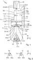
- Fig. 1 shows a method according to the invention.
- the method is designed for docking an autonomous mobile green area processing robot 20 to a docking station 60.
- An electrical conductor arrangement 70 runs in the area of the docking station 60.
- the conductor arrangement 70 is designed so that a periodic current I (t) flows through the conductor arrangement 70, as in FIG Figs. 1 to 3 , 5 and 7th shown.
- the current I (t) generates a periodic magnetic field B (t).
- the green area processing robot 20 has two magnetic field sensors 21a, 21b.
- the two magnetic field sensors 21a, 21b are designed so that the magnetic field B (t) in the magnetic field sensors 21a, 21b each causes a periodic sensor signal S21a (t), S21b (t), as in FIG Figures 4 and 6 shown.
- the method has the steps: a) determining a phase shift PV between the two sensor signals S21a (t), S21b (t), as in FIG Fig. 8 shown. b) Controlling a movement of the green area processing robot 20 for docking as a function of the determined phase shift PV.
- the system 1 according to the invention has at least one green area processing system 10 according to the invention and at least one docking station system 50 according to the invention.
- the green area processing system 10 has the green area processing robot 20, a determination device 22 and a control device 23.
- the Green area processing robot 20 is designed for docking with docking station 60.
- the green area processing robot 20 has the two magnetic field sensors 21a, 21b.
- the two magnetic field sensors 21a, 21b are designed so that the periodic magnetic field B (t) in the magnetic field sensors 21a, 21b each causes the periodic sensor signal S21a (t), S21b (t).
- the determination device 22 is designed to determine the phase shift PV between the two sensor signals S21a (t), S21b (t).
- the control device 23 is designed to control the movement of the green area processing robot 20 for docking as a function of the determined phase shift PV.
- the green area processing system 10 is designed to carry out the method.
- the green area processing robot 20 has the determination device 22 and the control device 23.
- the docking station system 50 has the docking station 60 and the electrical conductor arrangement 70 running in the area of the docking station 60.
- the docking station 60 is designed for docking with the green area processing robot 20.
- the conductor arrangement 70 is designed so that the periodic current I (t) flows through the conductor arrangement 70.
- the current I (t) generates the periodic magnetic field B (t).
- the docking station system 50 has a plate 55.
- the conductor arrangement 70 is laid in the plate 55.
- the docking station 60 has a station docking axis 60A, in particular a station center axis, in FIG Fig. 1 in a horizontal direction y.
- the conductor arrangement 70 runs with at least one conductor section 71a, 71b approximately parallel to the station docking axis 60A.
- the conductor arrangement 70 has at least two conductor sections 71a, 71b.
- the two conductor sections 71a, 71b each run approximately parallel to the station docking axis 60A.
- the two conductor sections 71a, 71b point from the station docking axis 60A in an orthogonal to the station docking axis 60A, in Fig. 1 horizontal, conductor spacing direction x different conductor spacings 71aD ', 72bD'.
- the two conductor sections 71a, 71b close to the docking station 60 from the station docking axis 60A have the different conductor spacings 71a, D ', 71bD', which are small in the exemplary embodiment shown.
- the two conductor sections 71a, 71b at a distance from the docking station 60 from the station docking axis 60A have the same conductor spacings 71aD ", 71bD", which are large in the exemplary embodiment shown.
- the two conductor sections 71a, 71b have a total conductor spacing 71aD '+ 71bD' from one another in the conductor spacing direction x which is orthogonal to the station docking axis 60A, in particular close to the docking station 60.
- the total conductor spacing 71aD '+ 71bD' is a sum of the various conductor spacings 71aD ', 71bD'.
- Step b) comprises: controlling in such a way that the green area processing robot 20 moves with its robot docking axis 20A, oriented approximately coaxially to the station docking axis 60A, to the docking station 60.
- the two magnetic field sensors 21a, 21b point from the robot docking axis 20A in an orthogonal to the robot docking axis 20A, in Fig. 1 horizontal, sensor distance direction x equal sensor distances 21aD, 21bD.
- the two magnetic field sensors 21a, 21b have a total sensor distance 21aD + 21bD from one another in the sensor distance direction x orthogonal to the robot docking axis 20A.
- the total conductor distance 71aD '+ 71bD' is different from that, in the exemplary embodiment shown, greater than the total sensor distance 21aD + 21bD.
- the sum sensor distance 21aD + 21bD is a sum of the same sensor distances 21aD, 21bD.
- the docking station 60 is also designed as a charging station.
- the docking station 60 has at least one station charging connection 65a, 65b, in the exemplary embodiment shown two station charging connections 65a, 65b.
- the docking station is for charging formed by the at least one station charging connection 62, 65b.
- the at least one station charging connection 65a, 65b defines the station docking axis 60A.
- the green space processing robot 20 is designed as a chargeable green space processing robot.
- the green area processing robot 20 has at least one robot charging connection 25a, 25b, in the exemplary embodiment shown, two robot charging connections 25a, 25b.
- the green area processing robot 20 is designed for charging by the at least one robot charging connection 25a, 25b.
- the at least one robot charging connection 25a, 25b defines the robot docking axis 20A.
- the conductor arrangement 70 is a loop, in particular a closed loop.
- the current I (t) flows away from the docking station 60 through the one conductor section 71a, counter to the horizontal direction y in the exemplary embodiment shown.
- the current I (t) through the one conductor section 71a generates the magnetic field B (t) with a field line direction, as in FIG Fig. 2 shown.
- the current I (t) flows through the other conductor section 71b to the docking station 60, in the illustrated embodiment in the horizontal direction y.
- the current I (t) through the other conductor section 71b generates the magnetic field B (t) with an opposite field line direction.
- Step b) further comprises: controlling such that the phase shift PV is in the range between 0 and ⁇ , in particular ⁇ / 2, as in FIG Fig. 1 and 8th shown.
- the green area processing robot 20 has a, in Fig. 1 horizontal, plane of motion 20E.
- the two magnetic field sensors 21a, 21b each have one, in particular one approximately orthogonal to and / or in the plane of movement 20E Figs. 1 and 2 vertical, detection direction z.
- the two magnetic field sensors 21a, 21b are designed so that only one parallel to the detection direction z, in Figs. 1 and 2 vertical, component Bz (t) of the magnetic field B (t) in the magnetic field sensors 21a, 21b causes the sensor signal S21a (t), S21b (t).
- one of the two magnetic field sensors 21a is designed or provided so that only the component Bz (t) of the magnetic field B (t) of the one conductor section 71a in the one magnetic field sensor 21a that is parallel to the detection direction z Sensor signal S21a (t), and another of the two magnetic field sensors 21b is designed or provided that only the component Bz (t) of the magnetic field B (t) of the other conductor section 71b in the other magnetic field sensor 21b that is parallel to the detection direction z Sensor signal S21b (t) caused.
- step b) comprises: controlling such that the detection direction z of the one magnetic field sensor 21a is orthogonal to the magnetic field B (t), in the exemplary embodiment shown, of the one conductor section 71a, and the detection direction z of the other magnetic field sensor 21b is non-orthogonal to the Magnetic field B (t), in the exemplary embodiment shown, of the other conductor section 71b.
- Step b) further comprises: controlling in such a way that the one magnetic field sensor 21a is positioned in the detection direction z above the at least one, in the exemplary embodiment shown, the one, conductor section 71a and the other magnetic field sensor 21b in the detection direction z is not above the at least one, in the exemplary embodiment shown, the other conductor section 71b is positioned, in particular the other magnetic field sensor 21b being positioned closer to the other conductor section 71b than the one conductor section 71a.
- the two magnetic field sensors 21a, 21b each have a coil 24a, 24b.
- the two coils 24a, 24b are designed so that the magnetic field B (t) in the coils 24a, 24b respectively causes the sensor signal S21a (t), S21b (t).
- the periodic current I (t) has a sinusoidal oscillation.
- the two sensor signals S21a (t), S21b (t) thus each have a sinusoidal oscillation, as in FIG Figures 4 and 6 shown.
- the one magnetic field sensor 21a in particular the one coil 24a, is positioned within the conductor arrangement 70 in the form of a loop or to the right of the one conductor section 71a.
- the one magnetic field sensor 21a is therefore not positioned above the one conductor section 71a.
- the detection direction z of the one magnetic field sensor 21a is thus non-orthogonal to the magnetic field B (t) of the one conductor section 71a.
- the other magnetic field sensor 21b in particular the one coil 24b, is positioned within the conductor arrangement 70 in the form of a loop or to the left of the other conductor section 71b.
- the other magnetic field sensor 21b is not positioned over the other conductor section 71b.
- the detection direction z of the other magnetic field sensor 21b is thus non-orthogonal to the magnetic field B (t) of the other conductor section 71b.
- the phase shift PV is 0 as in FIG Fig. 4 and 8th shown.
- the one magnetic field sensor 21a is positioned in the detection direction z above the one conductor section 71a, and thus that the detection direction z of the one magnetic field sensor 21a is orthogonal to the magnetic field B (t) of the one conductor section 71a, and thus that the phase shift PV is in the range between 0 and ⁇ , in particular ⁇ / 2.
- the one magnetic field sensor 21a in particular the one coil 24a, is positioned outside the conductor arrangement 70 in the form of a loop or to the left of the one conductor section 71a.
- the one magnetic field sensor 21a is therefore not positioned above the one conductor section 71a.
- the detection direction z of the one magnetic field sensor 21a is thus non-orthogonal to the magnetic field B (t) of the one conductor section 71a.
- the other magnetic field sensor 21b in particular the one coil 24b, is positioned within the conductor arrangement 70 in the form of a loop or to the left of the other conductor section 71b.
- the other magnetic field sensor 21b is not positioned over the other conductor section 71b.
- the detection direction z of the other magnetic field sensor 21b is thus non-orthogonal to the magnetic field B (t) of the other conductor section 71b.
- the sensor signals S21a (t), S21b (t) or their sinusoidal oscillations are therefore out of phase, as in FIG Fig. 6 shown.
- the phase shift PV is ⁇ , as in Fig. 6 and 8th shown.
- the one magnetic field sensor 21a is positioned in the detection direction z above the one conductor section 71a, and thus that the detection direction z of the one magnetic field sensor 21a is orthogonal to the magnetic field B (t) of the one conductor section 71a, and thus that the phase shift PV is in the range between 0 and ⁇ , in particular ⁇ / 2.
- the one magnetic field sensor 21a in particular the one coil 24a, is positioned above the conductor arrangement 70 or above the one conductor section 71a.
- the detection direction z of the one magnetic field sensor 21a is thus orthogonal to the magnetic field B (t) of the one conductor section 71a.
- the other magnetic field sensor 21b in particular the one coil 24b, is positioned within the conductor arrangement 70 in the form of a loop or to the left of the other conductor section 71b.
- the other magnetic field sensor 21b is not positioned over the other conductor section 71b.
- the detection direction z of the other magnetic field sensor 21b is thus non-orthogonal to the magnetic field B (t) of the other conductor section 71b.
- the sensor signals S21a (t), S21b (t) or their sinusoidal oscillations thus change over a diameter of the coil 24a, in particular in the horizontal direction x, between in-phase and antiphase.
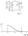
- the phase shift PV is in the range between 0 and ⁇ , in particular ⁇ / 2, as in FIG Fig. 8 shown.
- the one magnetic field sensor 21a is or remains positioned in the detection direction z over the one conductor section 71a, and thus that the detection direction z of the one magnetic field sensor 21a is orthogonal to the magnetic field B (t) of the one Conductor section 71a is or remains, and thus the phase shift PV is or remains in the range between 0 and ⁇ , in particular ⁇ / 2.
- the green area processing robot 20 thus follows the ladder arrangement 70, in particular until it is docked with the docking station 60.
- the method has the following step: positioning the green area processing robot 20 in the area of the magnetic field B (t) such that the magnetic field B (t) in at least one of the two magnetic field sensors 21a, 21b generates the sensor signal S21a (t), S21b (t) caused, as in Fig. 1 shown. Carrying out step a) and / or step b) in time thereafter.
- the positioning takes place by means of a further magnetic field of a further electrical conductor arrangement 75, in particular the system 1, in particular the docking station system 50.
- the invention provides an advantageous method for docking an autonomous mobile green space processing robot to a docking station, which method has improved properties. Furthermore, the invention provides an advantageous docking station system having a docking station, an advantageous green space processing system having an autonomous mobile green space processing robot and an advantageous system having such a green space processing system and, in particular, such a docking station system.
Landscapes
- Engineering & Computer Science (AREA)
- Remote Sensing (AREA)
- Radar, Positioning & Navigation (AREA)
- General Physics & Mathematics (AREA)
- Life Sciences & Earth Sciences (AREA)
- Automation & Control Theory (AREA)
- Physics & Mathematics (AREA)
- Power Engineering (AREA)
- Aviation & Aerospace Engineering (AREA)
- Environmental Sciences (AREA)
- Transportation (AREA)
- Mechanical Engineering (AREA)
- Geology (AREA)
- General Life Sciences & Earth Sciences (AREA)
- Environmental & Geological Engineering (AREA)
- Control Of Position, Course, Altitude, Or Attitude Of Moving Bodies (AREA)
- Manipulator (AREA)
- Guiding Agricultural Machines (AREA)
Abstract
- wobei im Bereich der Dockingstation (60) eine elektrische Leiteranordnung (70) verläuft, wobei die Leiteranordnung (70) dazu ausgebildet ist, dass durch die Leiteranordnung (70) ein periodischer Strom (l(t)) fließt, wobei der Strom (l(t)) ein periodisches Magnetfeld (B(t)) erzeugt,
- wobei der Grünflächenbearbeitungsroboter (20) zwei Magnetfeldsensoren (21a, 21b) aufweist, wobei die zwei Magnetfeldsensoren (21a, 21b) dazu ausgebildet sind, dass das Magnetfeld (B(t)) in den Magnetfeldsensoren (21a, 21b) jeweils ein periodisches Sensorsignal (S21a(t), S21b(t)) verursacht,
- wobei das Verfahren die Schritte aufweist:
a) Bestimmen einer Phasenverschiebung (PV) zwischen den zwei Sensorsignalen (S21a(t), S21b(t)) oder auf den Sensorsignalen (S21a(t), S21b(t)) basierenden Signalen, und
b) Steuern eines Bewegens des Grünflächenbearbeitungsroboters (20) zum Andocken in Abhängigkeit der bestimmten Phasenverschiebung (PV).
Description
- Die Erfindung bezieht sich auf ein Verfahren zum Andocken von einem autonomen mobilen Grünflächenbearbeitungsroboter an eine Dockingstation, ein Dockingstationsystem aufweisend eine Dockingstation und ein Grünflächenbearbeitungssystem aufweisend einen autonomen mobilen Grünflächenbearbeitungsroboter und ein System aufweisend ein solches Grünflächenbearbeitungssystem und ein, insbesondere solches, Dockingstationsystem.
- Der Erfindung liegt als Aufgabe die Bereitstellung eines Verfahrens zum Andocken von einem autonomen mobilen Grünflächenbearbeitungsroboter an eine Dockingstation zugrunde, das verbesserte Eigenschaften aufweist. Des Weiteren liegt der Erfindung als Aufgabe die Bereitstellung eines Dockingstationssystems aufweisend eine Dockingstation, eines Grünflächenbearbeitungssystem aufweisend einen autonomen mobilen Grünflächenbearbeitungsroboter und eines System aufweisend ein solches Grünflächenbearbeitungssystem und ein, insbesondere solches, Dockingstationsystem zugrunde.
- Die Erfindung löst diese Aufgabe durch die Bereitstellung eines Verfahrens mit den Merkmalen des Anspruchs 1. Des Weiteren wird die der Erfindung zugrundeliegende Aufgabe durch ein Dockingstationssystem mit den Merkmalen des Anspruchs 12, ein Grünflächenbearbeitungssystem mit den Merkmalen des Anspruchs 14 und ein System mit den Merkmalen des Anspruchs 15 gelöst. Vorteilhafte Weiterbildungen und/oder Ausgestaltungen der Erfindung sind in den abhängigen Ansprüchen beschrieben.
- Das erfindungsgemäße Verfahren ist zum, insbesondere automatischen, Andocken bzw. Eindocken von einem autonomen mobilen Grünflächenbearbeitungsroboter an eine Dockingstation ausgebildet bzw. konfiguriert. Im Bereich der Dockingstation verläuft eine elektrische Leiteranordnung. Die Leiteranordnung ist dazu ausgebildet bzw. konfiguriert, dass durch die Leiteranordnung ein, insbesondere elektrischer und/oder zeitlich, periodischer Strom fließt. Der Strom erzeugt bzw. verursacht ein, insbesondere zeitlich, periodisches Magnetfeld.
- Der Grünflächenbearbeitungsroboter weist zwei, insbesondere elektrische, Magnetfeldsensoren auf. Die zwei Magnetfeldsensoren sind dazu ausgebildet bzw. konfiguriert, dass das Magnetfeld in den Magnetfeldsensoren jeweils ein, insbesondere elektrisches und/oder zeitlich, periodisches Sensorsignal verursacht bzw. erzeugt. Das Verfahren weist die Schritte auf: a) Bestimmen, insbesondere automatisches Bestimmen, einer Phasenverschiebung bzw. eines Phasenversatzes bzw. einer Phasendifferenz zwischen den zwei Sensorsignalen oder auf den Sensorsignalen basierenden Signalen. b) Steuern, insbesondere automatisches Steuern, eines Bewegens des Grünflächenbearbeitungsroboters zum Andocken in Abhängigkeit der bestimmten Phasenverschiebung, insbesondere zeitlich nach dem Schritt a).
- Die Phasenverschiebung zwischen den zwei Sensorsignalen kann weniger oder sogar nicht von eventuellen externen Störungen des Magnetfelds und/oder internen Abweichungen bedingt durch Bauteil- und Fertigungstoleranzen zwischen den Magnetfeldsensoren beeinflusst sein, insbesondere im Unterschied zu Amplituden bzw. Stärken der Sensorsignale. Somit ermöglicht dies, dass das Andocken robust ist. Somit ermöglicht dies, dass das Andocken ohne zeitlich vorheriges Kalibrieren des Andockens erfolgen kann, insbesondere im Unterschied zu einem Andocken in Abhängigkeit von Amplituden, insbesondere einer Differenz der Amplituden, der Sensorsignale. Somit ermöglicht dies, dass das Andocken bei mehreren Dockingstationen erfolgen kann, insbesondere ohne verschiedene Kalibrierungen für die mehreren Dockingstationen, wenn überhaupt möglich.
- Insbesondere kann die Dockingstation zum Andocken von dem Grünflächenbearbeitungsroboter ausgebildet sein. Zusätzlich oder alternativ kann der Grünflächenbearbeitungsroboter zum Andocken an die Dockingstation ausgebildet sein.
- Autonom kann bedeuten, dass der Grünflächenbearbeitungsroboter sich selbstständig, selbsttätig, selbstbestimmt, selbstgesteuert, selbstgeführt und/oder unabhängig von einem Benutzer bewegen kann.
- Der Grünflächenbearbeitungsroboter kann als ein Rasenmähroboter ausgebildet sein.
- Die Leiteranordnung kann unter oder in einer Platte, insbesondere einer Boden- und/oder Fahrplatte, verlegt sein. Zusätzlich oder alternativ kann die Leiteranordnung eine, insbesondere geschlossene, Schleife, insbesondere Drahtschleife, sein.
- Der Strom kann eine Sinusschwingung aufweisen. Zusätzlich oder alternativ braucht der Strom nicht pausenlos zu fließen. Insbesondere kann der Strom in Form von periodischen Signalbursts fließen mit Pausen zwischen den Signalbursts. Insbesondere kann eine Zeitdauer des Flusses eines jeweiligen der Signalbursts einer Zeitdauer einer jeweiligen der Pausen entsprechen, insbesondere gleichen. Zusätzlich oder alternativ kann die Zeitdauer des Flusses eines jeweiligen der Signalbursts minimal 100 Millisekunden (ms) und/oder maximal 1000 ms sein und/oder die Zeitdauer einer jeweiligen der Pausen kann minimal 100 ms und/oder maximal 1000 ms sein. Weiter zusätzlich oder alternativ kann eine Periodizität zwischen einem jeweiligen der Signalbursts und einer jeweiligen der Pausen fix sein.
- Die zwei Magnetfeldsensoren können jeweils zum Erfassen und Umformen des Magnetfelds in das Sensorsignal ausgebildet sein. Zusätzlich oder alternativ können die zwei Magnetfeldsensoren voneinander einen Summensensorabstand aufweisen. Weiter zusätzlich oder alternativ kann der Grünflächenbearbeitungsroboter mindestens drei Magnetfeldsensoren aufweisen. Insbesondere kann ein dritter Magnetfeldsensor mit gegenüber den zwei Magnetfeldsensoren größerem Kopplungsfaktor eine Empfangsverbesserung auf großen Flächen ermöglichen.
- In einer Weiterbildung der Erfindung weist der Schritt b) auf: Steuern, insbesondere Regeln, derart, dass die Phasenverschiebung im Bereich zwischen 0 und π, insbesondere π/2, ist. Dies ermöglicht, dass der Grünflächenbearbeitungsroboter der Leiteranordnung folgt.
- In einer Weiterbildung der Erfindung weist die Dockingstation eine, insbesondere horizontale, Stationandockachse, insbesondere Stationmittelachse, auf. Die Leiteranordnung verläuft mit mindestens einem Leiterabschnitt etwa parallel zu der Stationandockachse. Dies ermöglicht, dass der Grünflächenbearbeitungsroboter sich zu der Dockingstation, insbesondere einer Mitte der Dockingstation bzw. mittig, bewegt. Insbesondere kann etwa parallel bedeuten, dass der Leiterabschnitt einen Winkel von maximal 5 Grad (°), insbesondere von maximal 2 °, insbesondere von maximal 1 °, zu der Stationandockachse aufweisen kann. Insbesondere kann der Leiterabschnitt parallel zu der Stationandockachse verlaufen.
- In einer Ausgestaltung der Erfindung weist der Grünflächenbearbeitungsroboter eine, insbesondere horizontale, Roboterandockachse, insbesondere Robotermittelachse bzw. Roboterlängsachse, auf. Der Schritt b) weist auf: Steuern derart, dass der Grünflächenbearbeitungsroboter sich mit seiner Roboterandockachse etwa koaxial zu der Stationandockachse ausgerichtet zu der Dockingstation bewegt. Dies ermöglicht, dass der Grünflächenbearbeitungsroboter zu der Dockingstation passend ausgerichtet ist. Insbesondere kann etwa koaxial bedeuten, dass die Roboterandockachse einen Winkel von maximal 5 °, insbesondere von maximal 2 °, insbesondere von maximal 1 °, zu der Stationandockachse aufweisen kann. Insbesondere kann die Roboterandockachse koaxial zu der Stationandockachse sein.
- In einer Ausgestaltung der Erfindung weist der Grünflächenbearbeitungsroboter eine, insbesondere horizontale, Bewegungsebene, insbesondere Fahrebene, auf. Die zwei Magnetfeldsensoren weisen jeweils eine zu der Bewegungsebene etwa orthogonale, insbesondere vertikale, Erfassungsrichtung auf. Des Weiteren sind die zwei Magnetfeldsensoren dazu ausgebildet bzw. konfiguriert, insbesondere ausgerichtet, dass nur eine zu der Erfassungsrichtung parallele, insbesondere vertikale, Komponente des Magnetfelds in den Magnetfeldsensoren jeweils das Sensorsignal verursacht. Der Schritt b) weist auf: Steuern derart, dass einer der zwei Magnetfeldsensoren in der Erfassungsrichtung über dem mindestens einen Leiterabschnitt positioniert ist und ein anderer der zwei Magnetfeldsensoren in der Erfassungsrichtung nicht über dem mindestens einen Leiterabschnitt positioniert ist. Insbesondere kann dies durch das Steuern derart, dass die Phasenverschiebung im Bereich zwischen 0 und π, insbesondere π/2, sein kann, ermöglicht sein oder werden. Insbesondere kann die Fahrebene durch Fahrräder des Grünflächenroboters definiert sein. Weiter zusätzlich oder alternativ kann etwa orthogonal bedeuten, dass die Erfassungsrichtung einen Winkel von minimal 85 °, insbesondere von minimal 88 °, insbesondere von minimal 89 °, zu der Bewegungsebene aufweisen kann. Insbesondere kann die Erfassungsrichtung orthogonal zu der Bewegungsebene sein. Weiter zusätzlich oder alternativ können die Erfassungsrichtungen zueinander parallel sein. Weiter zusätzlich oder alternativ können die zwei Magnetfeldsensoren jeweils zum Erfassen nur der zu der Erfassungsrichtung parallelen Komponente des Magnetfelds ausgebildet sein. Weiter zusätzlich oder alternativ kann der Leiterabschnitt etwa parallel zu der Bewegungsebene verlaufen.
- In einer Ausgestaltung der Erfindung weist die Leiteranordnung mindestens zwei Leiterabschnitte auf. Die zwei Leiterabschnitte verlaufen jeweils etwa parallel zu der Stationandockachse, insbesondere etwa parallel zu der Bewegungsebene. Des Weiteren weisen die zwei Leiterabschnitte voneinander in einer zu der Stationandockachse orthogonalen, insbesondere horizontalen und/oder zu der Bewegungsebene parallelen, Leiterabstandsrichtung einen Summenleiterabstand auf. Die zwei Magnetfeldsensoren weisen voneinander in einer zu der Roboterandockachse orthogonalen, insbesondere horizontalen und/oder zu der Bewegungsebene parallelen, Sensorabstandsrichtung einen Summensensorabstand auf. Der Summenleiterabstand, insbesondere ein Wert des Summenleiterabstands, ist verschieden von dem, insbesondere größer als der, Summensensorabstand, insbesondere ein Wert des Summensensorabstands. Insbesondere kann dies das Steuern derart, dass die Phasenverschiebung im Bereich zwischen 0 und π, insbesondere π/2, sein kann, ermöglichen. Zusätzlich oder alternativ kann dies das Steuern derart, dass der eine Magnetfeldsensor in der Erfassungsrichtung über dem einen Leiterabschnitt positioniert sein kann und der andere Magnetfeldsensor in der Erfassungsrichtung nicht über dem anderen Leiterabschnitt positioniert sein kann, ermöglichen. Insbesondere kann der andere Magnetfeldsensor dem anderen Leiterabschnitt näher als dem einen Leiterabschnitt positioniert sein oder werden. Zusätzlich oder alternativ kann der eine Magnetfeldsensor dazu ausgebildet bzw. positioniert sein, dass nur die zu der Erfassungsrichtung parallele Komponente des Magnetfelds des einen Leiterabschnitts in dem einen Magnetfeldsensor das Sensorsignal verursachen kann, und der andere Magnetfeldsensor kann dazu ausgebildet bzw. positioniert sein, dass nur die zu der Erfassungsrichtung parallele Komponente des Magnetfelds des anderen Leiterabschnitts in dem anderen Magnetfeldsensor das Sensorsignal verursachen kann. Weiter zusätzlich oder alternativ können die zwei Magnetfeldsensoren entlang der Roboterandockachse gleiche Abstände von einer Vorderseite bzw. Front des Grünflächenbearbeitungsroboters aufweisen. Weiter zusätzlich oder alternativ können die Leiterabstandsrichtung und die Sensorabstandsrichtung parallel sein.
- In einer Ausgestaltung der Erfindung weist die Leiteranordnung mindestens zwei Leiterabschnitte auf. Die zwei Leiterabschnitte verlaufen jeweils etwa parallel zu der Stationandockachse, insbesondere etwa parallel zu der Bewegungsebene. Des Weiteren weisen die zwei Leiterabschnitte von der Stationandockachse, insbesondere Stationmittelachse, in einer zu der Stationandockachse orthogonalen, insbesondere horizontalen und/oder zu der Bewegungsebene parallelen, Leiterabstandsrichtung verschiedene Leiterabstände, insbesondere verschiedene Werte der Leiterabstände, auf.
- Zusätzlich oder alternativ weisen die zwei Magnetfeldsensoren von der Roboterandockachse, insbesondere Robotermittelachse, in einer zu der Roboterandockachse orthogonalen, insbesondere horizontalen und/oder zu der Bewegungsebene parallelen, Sensorabstandsrichtung gleiche Sensorabstände, insbesondere gleiche Werte der Sensorabstände, auf.
- Insbesondere kann dies das Steuern derart, dass die Phasenverschiebung im Bereich zwischen 0 und π, insbesondere π/2, sein kann, ermöglichen. Zusätzlich oder alternativ kann dies das Steuern derart, dass der eine Magnetfeldsensor in der Erfassungsrichtung über dem einen Leiterabschnitt positioniert sein kann und der andere Magnetfeldsensor in der Erfassungsrichtung nicht über dem anderen Leiterabschnitt positioniert sein kann, ermöglichen. Insbesondere kann der andere Magnetfeldsensor dem anderen Leiterabschnitt näher als dem einen Leiterabschnitt positioniert sein oder werden. Zusätzlich oder alternativ kann der eine Magnetfeldsensor dazu ausgebildet bzw. positioniert sein, dass nur die zu der Erfassungsrichtung parallele Komponente des Magnetfelds des einen Leiterabschnitts in dem einen Magnetfeldsensor das Sensorsignal verursachen kann, und der andere Magnetfeldsensor kann dazu ausgebildet bzw. positioniert sein, dass nur die zu der Erfassungsrichtung parallele Komponente des Magnetfelds des anderen Leiterabschnitts in dem anderen Magnetfeldsensor das Sensorsignal verursachen kann. Weiter zusätzlich oder alternativ können die zwei Magnetfeldsensoren entlang der Roboterandockachse gleiche Abstände von einer Vorderseite bzw. Front des Grünflächenbearbeitungsroboters aufweisen. Weiter zusätzlich oder alternativ können die Leiterabstandsrichtung und die Sensorabstandsrichtung parallel sein.
- In einer Ausgestaltung der Erfindung ist die Dockingstation als eine, insbesondere elektrische, Ladestation ausgebildet bzw. konfiguriert. Des Weiteren weist die Dockingstation mindestens einen, insbesondere elektrischen, Stationladeanschluss auf. Die Dockingstation ist zum, insbesondere automatischen und/oder elektrischen, Aufladen durch den mindestens einen Stationladeanschluss ausgebildet bzw. konfiguriert. Der mindestens eine Stationladeanschluss definiert die Stationandockachse.
- Zusätzlich oder alternativ ist der Grünflächenbearbeitungsroboter als ein, insbesondere elektrisch, aufladbarer Grünflächenbearbeitungsroboter ausgebildet bzw. konfiguriert. Des Weiteren weist der Grünflächenbearbeitungsroboter mindestens einen, insbesondere elektrischen, Roboterladeanschluss auf. Der Grünflächenbearbeitungsroboter ist zum, insbesondere automatischen und/oder elektrischen, Aufladen durch den mindestens einen Roboterladeanschluss ausgebildet bzw. konfiguriert. Der mindestens eine Roboterladeanschluss definiert die Roboterandockachse.
- Dies ermöglicht, dass die Dockingstation den, insbesondere angedockten, Grünflächenbearbeitungsroboter aufladen kann.
- Insbesondere können der Stationladeanschluss und der Roboterladeanschluss sich zum Aufladen berühren. Zusätzlich oder alternativ können/kann der Stationladeanschluss und/oder der Roboterladeanschluss jeweils einen Ladekontakt aufweisen oder sein. Weiter zusätzlich oder alternativ kann der Grünflächenbearbeitungsroboter einen Akkumulator aufweisen. Der Akkumulator kann zur Versorgung eines Bearbeitungsantriebs, insbesondere eines Rasenmähantriebs, und/oder eines Bewegungsantriebs, insbesondere eines Fahrantriebs, des Grünflächenbearbeitungsroboters ausgebildet sein. Des Weiteren kann der Akkumulator zum Aufladen durch den Roboterladeanschluss ausgebildet sein.
- In einer Weiterbildung der Erfindung weisen die zwei Magnetfeldsensoren jeweils eine, insbesondere vertikale und/oder zu der Bewegungsebene orthogonale, Erfassungsrichtung auf. Des Weiteren sind die zwei Magnetfeldsensoren dazu ausgebildet bzw. konfiguriert, insbesondere ausgerichtet, dass nur eine zu der Erfassungsrichtung parallele, insbesondere vertikale, Komponente des Magnetfelds in den Magnetfeldsensoren jeweils das Sensorsignal verursacht. Der Schritt b) weist auf: Steuern derart, dass die Erfassungsrichtung eines der zwei Magnetfeldsensoren, insbesondere an der Position des einen Magnetfeldsensors, orthogonal zu dem Magnetfeld ist und die Erfassungsrichtung eines anderen der zwei Magnetfeldsensoren, insbesondere an der Position des anderen Magnetfeldsensors, nicht-orthogonal, insbesondere parallel, zu dem Magnetfeld ist. Insbesondere kann dies durch das Steuern derart, dass die Phasenverschiebung im Bereich zwischen 0 und π, insbesondere π/2, sein kann, ermöglicht sein oder werden. Zusätzlich oder alternativ kann dies das Steuern derart, dass der eine Magnetfeldsensor in der Erfassungsrichtung über dem mindestens einen Leiterabschnitt positioniert sein kann und der andere Magnetfeldsensor in der Erfassungsrichtung nicht über dem mindestens einen Leiterabschnitt positioniert sein kann, ermöglichen. Insbesondere können die Erfassungsrichtungen zueinander parallel sein. Zusätzlich oder alternativ können die zwei Magnetfeldsensoren jeweils zum Erfassen nur der zu der Erfassungsrichtung parallelen Komponente des Magnetfelds ausgebildet sein. Weiter zusätzlich oder alternativ kann der eine Magnetfeldsensor dazu ausgebildet bzw. positioniert sein, dass nur die zu der Erfassungsrichtung parallele Komponente des Magnetfelds des einen Leiterabschnitts in dem einen Magnetfeldsensor das Sensorsignal verursachen kann, und der andere Magnetfeldsensor kann dazu ausgebildet bzw. positioniert sein, dass nur die zu der Erfassungsrichtung parallele Komponente des Magnetfelds des anderen Leiterabschnitts in dem anderen Magnetfeldsensor das Sensorsignal verursachen kann. Weiter zusätzlich oder alternativ kann das Steuern derart sein, dass die Erfassungsrichtung des einen Magnetfeldsensors orthogonal zu dem Magnetfeld des einen Leiterabschnitts sein kann und die Erfassungsrichtung des anderen Magnetfeldsensors nicht-orthogonal zu dem Magnetfeld des anderen Leiterabschnitts sein kann.
- In einer Weiterbildung der Erfindung weisen die zwei Magnetfeldsensoren jeweils eine, insbesondere elektrische, Spule auf. Die zwei Spulen sind dazu ausgebildet bzw. konfiguriert, dass das Magnetfeld in den Spulen jeweils das Sensorsignal verursacht bzw. induziert. Dies kann ermöglichen, dass die zwei Magnetfeldsensoren dazu ausgebildet sein können, dass nur die zu der Erfassungsrichtung parallele Komponente des Magnetfelds in den Magnetfeldsensoren jeweils das Sensorsignal verursachen kann. Insbesondere können die zwei Spulen jeweils zum Erfassen des Magnetfelds ausgebildet sein.
- In einer Weiterbildung der Erfindung weist das Verfahren den Schritt auf: Positionieren, insbesondere automatisches Positionieren, des Grünflächenbearbeitungsroboters im Bereich des Magnetfelds derart, dass das Magnetfeld in mindestens einem der zwei Magnetfeldsensoren, insbesondere jeweils, das Sensorsignal verursacht. Durchführen des Schritts a) und/oder des Schritts b) zeitlich danach, insbesondere zeitlich nach dem Positionieren. Insbesondere kann das Positionieren derart sein, dass mindestens einer der zwei Magnetfeldsensoren das Magnetfeld erfassen kann. Zusätzlich oder alternativ kann das Positionieren mittels eines weiteren Magnetfelds einer weiteren elektrischen Leiteranordnung erfolgen. Insbesondere kann die Leiteranordnung als Dockleiteranordnung bezeichnet werden und/oder die weitere Leiteranordnung kann als Begrenzungsleiteranordnung bezeichnet werden.
- Das erfindungsgemäße Dockingstationsystem weist eine, insbesondere die, Dockingstation und eine, insbesondere die, eine elektrische Leiteranordnung im Bereich der Dockingstation auf. Die Dockingstation ist zum Andocken von einem, insbesondere dem, autonomen mobilen Grünflächenbearbeitungsroboter ausgebildet bzw. konfiguriert. Des Weiteren weist die Dockingstation eine, insbesondere die, Stationandockachse auf. Die Leiteranordnung weist, insbesondere die, mindestens zwei Leiterabschnitte auf. Die zwei Leiterabschnitte verlaufen jeweils etwa parallel zu der Stationandockachse. Außerdem weisen die zwei Leiterabschnitte von der Stationandockachse, insbesondere Stationmittelachse, in einer, insbesondere der, zu der Stationandockachse orthogonalen Leiterabstandsrichtung verschiedene Leiterabstände auf. Die Leiteranordnung ist dazu ausgebildet bzw. konfiguriert, dass durch die Leiteranordnung ein, insbesondere der, periodischer Strom fließt. Der Strom erzeugt ein, insbesondere das, periodisches Magnetfeld.
- Das Dockingstationsystem kann die gleichen Vorteile ermöglichen wie das zuvor beschriebene Verfahren.
- Insbesondere können/kann die Dockingstation und/oder die Leiteranordnung wie zuvor für das Verfahren beschrieben ausgebildet sein. Insbesondere kann das Dockingstationsystem die Platte aufweisen. Zusätzlich oder alternativ kann das Dockingstationsystem, insbesondere die Dockingstation, eine Stromquelle aufweisen. Die Stromquelle kann zum Erzeugen des Stroms durch die Leiteranordnung ausgebildet sein.
- In einer Weiterbildung der Erfindung weisen die zwei Leiterabschnitte nah an der Dockingstation von der Stationandockachse, insbesondere in der Leiterabstandsrichtung, die verschiedenen, insbesondere kleinen, Leiterabstände, insbesondere Werte der Leiterabstände, auf. Des Weiteren weisen die zwei Leiterabschnitte entfernt von der Dockingstation von der Stationandockachse, insbesondere in der Leiterabstandsrichtung, gleiche, insbesondere große, Leiterabstände, insbesondere Werte der Leiterabstände, auf. Dies ermöglicht, dass das Magnetfeld von der Dockingstation mit dem angedockten Grünflächenbearbeitungsroboter weit weg reichen bzw. ferner wirken kann und somit einen weiteren Grünflächenbearbeitungsroboter fern halten kann.
- Das erfindungsgemäße Grünflächenbearbeitungssystem weist einen, insbesondere den, autonomen mobilen Grünflächenbearbeitungsroboter, eine, insbesondere elektrische, Bestimmungseinrichtung und eine, insbesondere elektrische, Steuerungseinrichtung auf. Der Grünflächenbearbeitungsroboter ist zum, insbesondere automatischen, Andocken an eine, insbesondere die, Dockingstation ausgebildet bzw. konfiguriert. Des Weiteren weist der Grünflächenbearbeitungsroboter, insbesondere die, zwei Magnetfeldsensoren auf. Die zwei Magnetfeldsensoren sind dazu ausgebildet bzw. konfiguriert, dass ein, insbesondere das, periodisches Magnetfeld in den Magnetfeldsensoren jeweils ein, insbesondere das, periodisches Sensorsignal verursacht. Die Bestimmungseinrichtung ist zum, insbesondere automatischen, Bestimmen einer, insbesondere der, Phasenverschiebung zwischen den zwei Sensorsignalen oder auf den Sensorsignalen basierenden Signalen ausgebildet bzw. konfiguriert. Die Steuerungseinrichtung ist zum, insbesondere automatischen, Steuern eines, insbesondere des, Bewegens des Grünflächenbearbeitungsroboters zum Andocken in Abhängigkeit der bestimmten Phasenverschiebung ausgebildet bzw. konfiguriert.
- Das Grünflächenbearbeitungssystem kann die gleichen Vorteile ermöglichen wie das zuvor beschriebene Verfahren.
- Insbesondere kann das Grünflächenbearbeitungssystem zum Durchführen des zuvor beschriebenen Verfahrens ausgebildet sein. Zusätzlich oder alternativ kann der Grünflächenbearbeitungsroboter wie zuvor für das Verfahren beschrieben ausgebildet sein. Weiter zusätzlich oder alternativ kann der Grünflächenbearbeitungsroboter die Bestimmungseinrichtung und/oder die Steuerungseinrichtung aufweisen.
- Das erfindungsgemäße System weist mindestens ein, insbesondere das, Grünflächenbearbeitungssystem wie zuvor beschrieben und mindestens ein, insbesondere das, Dockingstationsystem, insbesondere wie zuvor beschrieben, auf. Das Dockingstationsystem weist eine, insbesondere die, Dockingstation und eine, insbesondere die, im Bereich der Dockingstation verlaufende elektrische Leiteranordnung auf. Die Dockingstation ist zum Andocken von dem Grünflächenbearbeitungsroboter ausgebildet bzw. konfiguriert. Die Leiteranordnung ist dazu ausgebildet bzw. konfiguriert, dass durch die Leiteranordnung ein, insbesondere der, periodischer Strom fließt. Der Strom erzeugt ein, insbesondere das, periodisches Magnetfeld. Insbesondere kann das System mehrere Grünflächenbearbeitungssysteme und/oder mehrere Dockingstationsysteme aufweisen.
- Weitere Vorteile und Aspekte der Erfindung ergeben sich aus den Ansprüchen und aus der nachfolgenden Beschreibung von bevorzugten Ausführungsbeispielen der Erfindung, die nachfolgend anhand der Figuren erläutert sind. Dabei zeigen:
- Fig. 1
- eine Draufsicht auf ein erfindungsgemäßes System aufweisend ein erfindungsgemäßes Dockingstationssystem aufweisend eine Dockingstation und eine elektrische Leiteranordnung und ein erfindungsgemäßes Grünflächenbearbeitungssystem aufweisend einen autonomen mobilen Grünflächenbearbeitungsroboter, eine Bestimmungseinrichtung und eine Steuerungseinrichtung und ein erfindungsgemäßes Verfahren zum Andocken von dem Grünflächenbearbeitungsroboter an die Dockingstation,
- Fig. 2
- eine Seitenansicht auf die Leiteranordnung der
Fig. 1 aufweisend mindestens zwei Leiterabschnitte, durch die ein periodischer Strom fließt, der ein periodisches Magnetfeld erzeugt, - Fig. 3
- eine Draufsicht auf die Leiteranordnung der
Fig. 1 und zwei Magnetfeldsensoren des Grünflächenbearbeitungsroboters derFig. 1 , - Fig. 4
- einen Graph von Amplituden von periodischen Sensorsignalen der Magnetfeldsensoren der
Fig. 3 über der Zeit, - Fig. 5
- eine weitere Draufsicht auf die Leiteranordnung und die Magnetfeldsensoren der
Fig. 1 , - Fig. 6
- einen Graph von den Amplituden von den Sensorsignalen der Magnetfeldsensoren der
Fig. 5 über der Zeit, - Fig. 7
- eine weitere Draufsicht auf die Leiteranordnung und die Magnetfeldsensoren der
Fig. 1 , und - Fig. 8
- einen Graph einer Phasenverschiebung zwischen den Sensorsignalen der Magnetfeldsensoren der
Fig. 3, 5 und7 . -
Fig. 1 zeigt ein erfindungsgemäßes Verfahren. Das Verfahren ist zum Andocken von einem autonomen mobilen Grünflächenbearbeitungsroboter 20 an eine Dockingstation 60 ausgebildet. Im Bereich der Dockingstation 60 verläuft eine elektrische Leiteranordnung 70. Die Leiteranordnung 70 ist dazu ausgebildet, dass durch die Leiteranordnung 70 ein periodischer Strom I(t) fließt, wie inFig. 1 bis 3 ,5 und7 gezeigt. Der Strom I(t) erzeugt ein periodisches Magnetfeld B(t). Der Grünflächenbearbeitungsroboter 20 weist zwei Magnetfeldsensoren 21a, 21b auf. Die zwei Magnetfeldsensoren 21a, 21b sind dazu ausgebildet, dass das Magnetfeld B(t) in den Magnetfeldsensoren 21a, 21b jeweils ein periodisches Sensorsignal S21a(t), S21b(t) verursacht, wie inFig. 4 und 6 gezeigt. Das Verfahren weist die Schritte auf: a) Bestimmen einer Phasenverschiebung PV zwischen den zwei Sensorsignalen S21a(t), S21b(t), wie inFig. 8 gezeigt. b) Steuern eines Bewegens des Grünflächenbearbeitungsroboters 20 zum Andocken in Abhängigkeit der bestimmten Phasenverschiebung PV. - Das erfindungsgemäße System 1 weist mindestens ein erfindungsgemäßes Grünflächenbearbeitungssystem 10 und mindestens ein erfindungsgemäßes Dockingstationsystem 50 auf.
- Das Grünflächenbearbeitungssystem 10 weist den Grünflächenbearbeitungsroboter 20, eine Bestimmungseinrichtung 22 und eine Steuerungseinrichtung 23 auf. Der Grünflächenbearbeitungsroboter 20 ist zum Andocken an die Dockingstation 60 ausgebildet. Des Weiteren weist der Grünflächenbearbeitungsroboter 20 die zwei Magnetfeldsensoren 21a, 21b auf. Die zwei Magnetfeldsensoren 21a, 21b sind dazu ausgebildet, dass das periodische Magnetfeld B(t) in den Magnetfeldsensoren 21a, 21b jeweils das periodische Sensorsignal S21a(t), S21b(t) verursacht. Die Bestimmungseinrichtung 22 ist zum Bestimmen der Phasenverschiebung PV zwischen den zwei Sensorsignalen S21a(t), S21b(t) ausgebildet. Die Steuerungseinrichtung 23 ist zum Steuern des Bewegens des Grünflächenbearbeitungsroboters 20 zum Andocken in Abhängigkeit der bestimmten Phasenverschiebung PV ausgebildet.
- Im gezeigten Ausführungsbeispiel ist das Grünflächenbearbeitungssystem 10 zum Durchführen des Verfahrens ausgebildet. Zusätzlich weist im gezeigten Ausführungsbeispiel der Grünflächenbearbeitungsroboter 20 die Bestimmungseinrichtung 22 und die Steuerungseinrichtung 23 auf.
- Das Dockingstationsystem 50 weist die Dockingstation 60 und die im Bereich der Dockingstation 60 verlaufende elektrische Leiteranordnung 70 auf. Die Dockingstation 60 ist zum Andocken von dem Grünflächenbearbeitungsroboter 20 ausgebildet. Die Leiteranordnung 70 ist dazu ausgebildet, dass durch die Leiteranordnung 70 der periodische Strom I(t) fließt. Der Strom I(t) erzeugt das periodische Magnetfeld B(t).
- Im gezeigten Ausführungsbeispiel weist das Dockingstationsystem 50 eine Platte 55 auf. Die Leiteranordnung 70 ist in der Platte 55 verlegt.
- Im Detail weist die Dockingstation 60 eine Stationandockachse 60A, insbesondere Stationmittelachse, auf, in
Fig. 1 in einer horizontalen Richtung y. Die Leiteranordnung 70 verläuft mit mindestens einem Leiterabschnitt 71a, 71b etwa parallel zu der Stationandockachse 60A. - Im gezeigten Ausführungsbeispiel weist die Leiteranordnung 70 mindestens zwei Leiterabschnitte 71a, 71b auf. Die zwei Leiterabschnitte 71a, 71b verlaufen jeweils etwa parallel zu der Stationandockachse 60A.
- Des Weiteren weisen die zwei Leiterabschnitte 71a, 71b von der Stationandockachse 60A in einer zu der Stationandockachse 60A orthogonalen, in
Fig. 1 horizontalen, Leiterabstandsrichtung x verschiedene Leiterabstände 71aD', 72bD' auf. - Im Detail weisen die zwei Leiterabschnitte 71a, 71b nah an der Dockingstation 60 von der Stationandockachse 60A die verschiedenen, im gezeigten Ausführungsbeispiel kleinen, Leiterabstände 71a,D', 71bD' auf. Außerdem weisen die zwei Leiterabschnitte 71a, 71b entfernt von der Dockingstation 60 von der Stationandockachse 60A gleiche, im gezeigten Ausführungsbeispiel große, Leiterabstände 71aD", 71bD" auf.
- Weiter weisen die zwei Leiterabschnitte 71a, 71b voneinander in der zu der Stationandockachse 60A orthogonalen Leiterabstandsrichtung x, insbesondere nah an der Dockingstation 60, einen Summenleiterabstand 71aD'+71bD' auf.
- Im gezeigten Ausführungsbeispiel ist der Summenleiterabtsand 71aD'+71bD' eine Summe der verschiedenen Leiterabstände 71aD', 71bD'.
- Zudem weist der Grünflächenbearbeitungsroboter 20 eine Roboterandockachse 20A, insbesondere Robotermittelachse, auf, in
Fig. 1 in der horizontalen Richtung y. Der Schritt b) weist auf: Steuern derart, dass der Grünflächenbearbeitungsroboter 20 sich mit seiner Roboterandockachse 20A etwa koaxial zu der Stationandockachse 60A ausgerichtet zu der Dockingstation 60 bewegt. - Des Weiteren weisen die zwei Magnetfeldsensoren 21a, 21b von der Roboterandockachse 20A in einer zu der Roboterandockachse 20A orthogonalen, in
Fig. 1 horizontalen, Sensorabstandsrichtung x gleiche Sensorabstände 21aD, 21bD auf. - Außerdem weisen die zwei Magnetfeldsensoren 21a, 21b voneinander in der zu der Roboterandockachse 20A orthogonalen Sensorabstandsrichtung x einen Summensensorabstand 21aD+21bD auf. Der Summenleiterabstand 71aD'+71bD' ist verschieden von dem, im gezeigten Ausführungsbeispiel größer als der, Summensensorabstand 21aD+21bD.
- Im gezeigten Ausführungsbeispiel ist der Summensensorabstand 21aD+21bD eine Summe der gleichen Sensorabstände 21aD, 21bD.
- Weiter ist die Dockingstation 60 als eine Ladestation ausgebildet. Zudem weist die Dockingstation 60 mindestens einen Stationladeanschluss 65a, 65b auf, im gezeigten Ausführungsbeispiel zwei Stationladeanschlüsse 65a, 65b. Die Dockingstation ist zum Aufladen durch den mindestens einen Stationladeanschluss 62, 65b ausgebildet. Der mindestens eine Stationladeanschluss 65a, 65b definiert die Stationandockachse 60A.
- Des Weiteren ist der Grünflächenbearbeitungsroboter 20 als ein aufladbarer Grünflächenbearbeitungsroboter ausgebildet. Außerdem weist der Grünflächenbearbeitungsroboter 20 mindestens einen Roboterladeanschluss 25a, 25b auf, im gezeigten Ausführungsbeispiel zwei Roboterladeanschlüsse 25a, 25b. Der Grünflächenbearbeitungsroboter 20 ist zum Aufladen durch den mindestens einen Roboterladeanschluss 25a, 25b ausgebildet. Der mindestens eine Roboterladeanschluss 25a, 25b definiert die Roboterandockachse 20A.
- Im gezeigten Ausführungsbeispiel ist die Leiteranordnung 70 eine, insbesondere geschlossene, Schleife. Durch den einen Leiterabschnitt 71a fließt der Strom I(t) von der Dockingstation 60 weg, im gezeigten Ausführungsbeispiel entgegen der horizontalen Richtung y. Der Strom I(t) durch den einen Leiterabschnitt 71a erzeugt das Magnetfeld B(t) mit einer Feldlinienrichtung, wie in
Fig. 2 gezeigt. Durch den anderen Leiterabschnitt 71b fließt der Strom I(t) zu der Dockingstation 60 hin, im gezeigten Ausführungsbeispiel in der horizontalen Richtung y. Der Strom I(t) durch den anderen Leiterabschnitt 71b erzeugt das Magnetfeld B(t) mit einer entgegengesetzten Feldlinienrichtung. - Weiter weist der Schritt b) auf: Steuern derart, dass die Phasenverschiebung PV im Bereich zwischen 0 und π, insbesondere π/2, ist, wie in
Fig. 1 und8 gezeigt. - Zudem weist der Grünflächenbearbeitungsroboter 20 eine, in
Fig. 1 horizontale, Bewegungsebene 20E auf. - Des Weiteren weisen die zwei Magnetfeldsensoren 21a, 21b jeweils eine, insbesondere zu der Bewegungsebene 20E etwa orthogonale und/oder in
Fig. 1 und 2 vertikale, Erfassungsrichtung z auf. Außerdem sind die zwei Magnetfeldsensoren 21a, 21b dazu ausgebildet, dass nur eine zu der Erfassungsrichtung z parallele, inFig. 1 und 2 vertikale, Komponente Bz (t) des Magnetfelds B(t) in den Magnetfeldsensoren 21a, 21 b jeweils das Sensorsignal S21a(t), S21b(t) verursacht. - Im gezeigten Ausführungsbeispiel ist einer der zwei Magnetfeldsensoren 21a dazu ausgebildet bzw. vorgesehen, dass nur die zu der Erfassungsrichtung z parallele Komponente Bz(t) des Magnetfelds B(t) des einen Leiterabschnitts 71a in dem einen Magnetfeldsensor 21a das Sensorsignal S21a(t) verursacht, und ein anderer der zwei Magnetfeldsensoren 21b ist dazu ausgebildet bzw. vorgesehen, dass nur die zu der Erfassungsrichtung z parallele Komponente Bz(t) des Magnetfelds B(t) des anderen Leiterabschnitts 71b in dem anderen Magnetfeldsensor 21b das Sensorsignal S21b(t) verursacht.
- Zudem weist der Schritt b) auf: Steuern derart, dass die Erfassungsrichtung z des einen Magnetfeldsensors 21a orthogonal zu dem Magnetfeld B(t), im gezeigten Ausführungsbeispiel des einen Leiterabschnitts 71a, ist und die Erfassungsrichtung z des anderen Magnetfeldsensors 21b nicht-orthogonal zu dem Magnetfeld B(t), im gezeigten Ausführungsbeispiel des anderen Leiterabschnitts 71b, ist.
- Weiter weist der Schritt b) auf: Steuern derart, dass der eine Magnetfeldsensor 21a in der Erfassungsrichtung z über dem mindestens einen, im gezeigten Ausführungsbeispiel dem einen, Leiterabschnitt 71a positioniert ist und der andere Magnetfeldsensor 21b in der Erfassungsrichtung z nicht über dem mindestens einen, im gezeigten Ausführungsbeispiel dem anderen, Leiterabschnitt 71b positioniert ist, insbesondere wobei der andere Magnetfeldsensor 21b dem anderen Leiterabschnitt 71b näher als dem einen Leiterabschnitt 71a positioniert ist.
- Zudem weisen die zwei Magnetfeldsensoren 21a, 21b jeweils eine Spule 24a, 24b auf. Die zwei Spulen 24a, 24b sind dazu ausgebildet, dass das Magnetfeld B(t) in den Spulen 24a, 24b jeweils das Sensorsignal S21a(t), S21b(t) verursacht.
- Im gezeigten Ausführungsbeispiel weist der periodische Strom I(t) eine Sinusschwingung auf. Somit weisen die zwei Sensorsignale S21a(t), S21b(t) jeweils eine Sinusschwingung auf, wie in
Fig. 4 und 6 gezeigt. - In
Fig. 3 ist der eine Magnetfeldsensor 21a, insbesondere die eine Spule 24a, innerhalb der Leiteranordnung 70 in Form der Schleife bzw. rechts von dem einen Leiterabschnitt 71a positioniert. Somit ist der eine Magnetfeldsensor 21a nicht über dem einen Leiterabschnitt 71a positioniert. Somit ist die Erfassungsrichtung z des einen Magnetfeldsensors 21a nicht-orthogonal zu dem Magnetfeld B(t) des einen Leiterabschnitts 71a. Der andere Magnetfeldsensor 21b, insbesondere die eine Spule 24b, ist innerhalb der Leiteranordnung 70 in Form der Schleife bzw. links von dem anderen Leiterabschnitt 71b positioniert. Somit ist der andere Magnetfeldsensor 21b nicht über dem anderen Leiterabschnitt 71b positioniert. Somit ist die Erfassungsrichtung z des anderen Magnetfeldsensors 21b nicht-orthogonal zu dem Magnetfeld B(t) des anderen Leiterabschnitts 71b. Somit sind die Sensorsignale S21a(t), S21b(t) bzw. ihre Sinusschwingungen gleichphasig, wie inFig. 4 gezeigt. Somit ist die Phasenverschiebung PV 0, wie inFig. 4 und8 gezeigt. Somit wird das Bewegen des Grünflächenbearbeitungsroboters 20 zum Andocken inFig. 3 nach links, und insbesondere oben, gesteuert und somit derart, dass der eine Magnetfeldsensor 21a in der Erfassungsrichtung z über dem einen Leiterabschnitt 71a positioniert ist, und somit dass die Erfassungsrichtung z des einen Magnetfeldsensors 21a orthogonal zu dem Magnetfeld B(t) des einen Leiterabschnitts 71a ist, und somit dass die Phasenverschiebung PV im Bereich zwischen 0 und π, insbesondere π/2, ist. - In
Fig. 5 ist der eine Magnetfeldsensor 21a, insbesondere die eine Spule 24a, außerhalb der Leiteranordnung 70 in Form der Schleife bzw. links von dem einen Leiterabschnitt 71a positioniert. Somit ist der eine Magnetfeldsensor 21a nicht über dem einen Leiterabschnitt 71a positioniert. Somit ist die Erfassungsrichtung z des einen Magnetfeldsensors 21a nicht-orthogonal zu dem Magnetfeld B(t) des einen Leiterabschnitts 71a. Der andere Magnetfeldsensor 21b, insbesondere die eine Spule 24b, ist innerhalb der Leiteranordnung 70 in Form der Schleife bzw. links von dem anderen Leiterabschnitt 71b positioniert. Somit ist der andere Magnetfeldsensor 21b nicht über dem anderen Leiterabschnitt 71b positioniert. Somit ist die Erfassungsrichtung z des anderen Magnetfeldsensors 21b nicht-orthogonal zu dem Magnetfeld B(t) des anderen Leiterabschnitts 71b. Somit sind die Sensorsignale S21a(t), S21b(t) bzw. ihre Sinusschwingungen gegenphasig, wie inFig. 6 gezeigt. Somit ist die Phasenverschiebung PV π, wie inFig. 6 und8 gezeigt. Somit wird das Bewegen des Grünflächenbearbeitungsroboters 20 zum Andocken inFig. 5 nach rechts, und insbesondere oben, gesteuert und somit derart, dass der eine Magnetfeldsensor 21a in der Erfassungsrichtung z über dem einen Leiterabschnitt 71a positioniert ist, und somit dass die Erfassungsrichtung z des einen Magnetfeldsensors 21a orthogonal zu dem Magnetfeld B(t) des einen Leiterabschnitts 71a ist, und somit dass die Phasenverschiebung PV im Bereich zwischen 0 und π, insbesondere π/2, ist. - In
Fig. 7 ist der eine Magnetfeldsensor 21a, insbesondere die eine Spule 24a, über der Leiteranordnung 70 bzw. über dem einen Leiterabschnitt 71a positioniert. Somit ist die Erfassungsrichtung z des einen Magnetfeldsensors 21a orthogonal zu dem Magnetfeld B(t) des einen Leiterabschnitts 71a. Der andere Magnetfeldsensor 21b, insbesondere die eine Spule 24b, ist innerhalb der Leiteranordnung 70 in Form der Schleife bzw. links von dem anderen Leiterabschnitt 71b positioniert. Somit ist der andere Magnetfeldsensor 21b nicht über dem anderen Leiterabschnitt 71b positioniert. Somit ist die Erfassungsrichtung z des anderen Magnetfeldsensors 21b nicht-orthogonal zu dem Magnetfeld B(t) des anderen Leiterabschnitts 71b. Somit ändern die Sensorsignale S21a(t), S21b(t) bzw. ihre Sinusschwingungen über einen Durchmesser der Spule 24a, insbesondere in der horizontalen Richtung x, zwischen gleichphasig und gegenphasig. Somit ist die Phasenverschiebung PV im Bereich zwischen 0 und π, insbesondere π/2, wie inFig. 8 gezeigt. Somit wird das Bewegen des Grünflächenbearbeitungsroboters 20 zum Andocken inFig. 7 geradeaus bzw. nach oben gesteuert und somit derart, dass der eine Magnetfeldsensor 21a in der Erfassungsrichtung z über dem einen Leiterabschnitt 71a positioniert ist bzw. bleibt, und somit dass die Erfassungsrichtung z des einen Magnetfeldsensors 21a orthogonal zu dem Magnetfeld B(t) des einen Leiterabschnitts 71a ist bzw. bleibt, und somit dass die Phasenverschiebung PV im Bereich zwischen 0 und π, insbesondere π/2, ist bzw. bleibt. - Somit folgt der Grünflächenbearbeitungsroboter 20 der Leiteranordnung 70, insbesondere bis zu einem Andocken an die Dockingstation 60.
- Des Weiteren weist das Verfahren den Schritt auf: Positionieren des Grünflächenbearbeitungsroboters 20 im Bereich des Magnetfelds B(t) derart, dass das Magnetfeld B(t) in mindestens einem der zwei Magnetfeldsensoren 21a, 21b das Sensorsignal S21a(t), S21b(t) verursacht, wie in
Fig. 1 gezeigt. Durchführen des Schritts a) und/oder des Schritts b) zeitlich danach. - Im gezeigten Ausführungsbeispiel erfolgt das Positionieren mittels eines weiteren Magnetfelds einer weiteren elektrischen Leiteranordnung 75, insbesondere des Systems 1, insbesondere des Dockingstationsystem 50.
- Wie die gezeigten und oben erläuterten Ausführungsbeispiele deutlich machen, stellt die Erfindung ein vorteilhaftes Verfahren zum Andocken von einem autonomen mobilen Grünflächenbearbeitungsroboter an eine Dockingstation bereit, das verbesserte Eigenschaften aufweist. Des Weiteren stellt die Erfindung ein vorteilhaftes Dockingstationssystem aufweisend eine Dockingstation, ein vorteilhaftes Grünflächenbearbeitungssystem aufweisend einen autonomen mobilen Grünflächenbearbeitungsroboter und ein vorteilhaftes System aufweisend ein solches Grünflächenbearbeitungssystem und ein, insbesondere solches, Dockingstationsystem bereit.
Claims (15)
- Verfahren zum Andocken von einem autonomen mobilen Grünflächenbearbeitungsroboter (20) an eine Dockingstation (60),- wobei im Bereich der Dockingstation (60) eine elektrische Leiteranordnung (70) verläuft, wobei die Leiteranordnung (70) dazu ausgebildet ist, dass durch die Leiteranordnung (70) ein periodischer Strom (I(t)) fließt, wobei der Strom (I(t)) ein periodisches Magnetfeld (B(t)) erzeugt,- wobei der Grünflächenbearbeitungsroboter (20) zwei Magnetfeldsensoren (21a, 21b) aufweist, wobei die zwei Magnetfeldsensoren (21a, 21b) dazu ausgebildet sind, dass das Magnetfeld (B(t)) in den Magnetfeldsensoren (21a, 21b) jeweils ein periodisches Sensorsignal (S21a(t), S21b(t)) verursacht,- wobei das Verfahren die Schritte aufweist:a) Bestimmen einer Phasenverschiebung (PV) zwischen den zwei Sensorsignalen (S21a(t), S21b(t)) oder auf den Sensorsignalen (S21a(t), S21b(t)) basierenden Signalen, undb) Steuern eines Bewegens des Grünflächenbearbeitungsroboters (20) zum Andocken in Abhängigkeit der bestimmten Phasenverschiebung (PV).
- Verfahren nach Anspruch 1,- wobei der Schritt b) aufweist: Steuern derart, dass die Phasenverschiebung (PV) im Bereich zwischen 0 und π ist.
- Verfahren nach Anspruch 1 oder 2,- wobei die Dockingstation (60) eine Stationandockachse (60A) aufweist,- wobei die Leiteranordnung (70) mit mindestens einem Leiterabschnitt (71a, 71b) etwa parallel zu der Stationandockachse (60A) verläuft.
- Verfahren nach Anspruch 3,- wobei der Grünflächenbearbeitungsroboter (20) eine Roboterandockachse (20A) aufweist,- wobei der Schritt b) aufweist: Steuern derart, dass der Grünflächenbearbeitungsroboter (20) sich mit seiner Roboterandockachse (20A) etwa koaxial zu der Stationandockachse (60A) ausgerichtet zu der Dockingstation (60) bewegt.
- Verfahren nach Anspruch 3 oder 4,- wobei der Grünflächenbearbeitungsroboter (20) eine Bewegungsebene (20E) aufweist,- wobei die zwei Magnetfeldsensoren (21a, 21b) jeweils eine zu der Bewegungsebene (20E) etwa orthogonale Erfassungsrichtung (z) aufweisen und dazu ausgebildet sind, dass nur eine zu der Erfassungsrichtung (z) parallele Komponente (Bz(t)) des Magnetfelds (B(t)) in den Magnetfeldsensoren (21a, 21b) jeweils das Sensorsignal (S21a(t), S21b(t)) verursacht,- wobei der Schritt b) aufweist: Steuern derart, dass einer der zwei Magnetfeldsensoren (21a) in der Erfassungsrichtung (z) über dem mindestens einen Leiterabschnitt (71a) positioniert ist und ein anderer der zwei Magnetfeldsensoren (21b) in der Erfassungsrichtung (z) nicht über dem mindestens einen Leiterabschnitt (71b) positioniert ist.
- Verfahren nach Anspruch 4 oder 5,- wobei die Leiteranordnung (70) mindestens zwei Leiterabschnitte aufweist (71a, 71b), wobei die zwei Leiterabschnitte (71a, 71b) jeweils etwa parallel zu der Stationandockachse (60A) verlaufen und voneinander in einer zu der Stationandockachse (60A) orthogonalen Leiterabstandsrichtung (x) einen Summenleiterabstand (71aD'+71bD') aufweisen, und- wobei die zwei Magnetfeldsensoren (21a, 21b) voneinander in einer zu der Roboterandockachse (20A) orthogonalen Sensorabstandsrichtung (x) einen Summensensorabstand (21aD+21bD) aufweisen,- wobei der Summenleiterabstand (71aD'+71bD') verschieden von dem Summensensorabstand (21aD+21bD) ist.
- Verfahren nach einem der Ansprüche 3 bis 6,- wobei die Leiteranordnung (70) mindestens zwei Leiterabschnitte (71a, 71b) aufweist, wobei die zwei Leiterabschnitte (71a, 71b) jeweils etwa parallel zu der Stationandockachse (60A) verlaufen und von der Stationandockachse (60A) in einer zu der Stationandockachse (60A) orthogonalen Leiterabstandsrichtung (x) verschiedene Leiterabstände (71aD', 71bD') aufweisen, und/oder- wobei die zwei Magnetfeldsensoren (21a, 21b) von der Roboterandockachse (20A) in einer zu der Roboterandockachse (20A) orthogonalen Sensorabstandsrichtung (x) gleiche Sensorabstände (21aD, 21bD) aufweisen.
- Verfahren nach einem der Ansprüche 3 bis 7,- wobei die Dockingstation (60) als eine Ladestation ausgebildet ist und mindestens einen Stationladeanschluss (65a, 65b) aufweist, wobei die Dockingstation (60) zum Aufladen durch den mindestens einen Stationladeanschluss (65a, 65b) ausgebildet ist, wobei der mindestens eine Stationladeanschluss (65a, 65b) die Stationandockachse (60A) definiert, und/oder- wobei der Grünflächenbearbeitungsroboter (20) als ein aufladbarer Grünflächenbearbeitungsroboter ausgebildet ist und mindestens einen Roboterladeanschluss (25a, 25b) aufweist, wobei der Grünflächenbearbeitungsroboter (20) zum Aufladen durch den mindestens einen Roboterladeanschluss (25a, 25b) ausgebildet ist, wobei der mindestens eine Roboterladeanschluss (25a, 25b) die Roboterandockachse (20A) definiert.
- Verfahren nach einem der vorhergehenden Ansprüche,- wobei die zwei Magnetfeldsensoren (21, 21b) jeweils eine Erfassungsrichtung (z) aufweisen und dazu ausgebildet sind, dass nur eine zu der Erfassungsrichtung (z) parallele Komponente (Bz(t)) des Magnetfelds (B(t)) in den Magnetfeldsensoren (21a, 21b) jeweils das Sensorsignal (S21a(t), S21b(t)) verursacht,- wobei der Schritt b) aufweist: Steuern derart, dass die Erfassungsrichtung (z) eines der zwei Magnetfeldsensoren (21a) orthogonal zu dem Magnetfeld (B(t)) ist und die Erfassungsrichtung (z) eines anderen der zwei Magnetfeldsensoren (21b) nicht-orthogonal zu dem Magnetfeld (B(t)) ist.
- Verfahren nach einem der vorhergehenden Ansprüche,- wobei die zwei Magnetfeldsensoren (21a, 21b) jeweils eine Spule (24a, 24b) aufweisen, wobei die zwei Spulen (24a, 24b) dazu ausgebildet sind, dass das Magnetfeld (B(t)) in den Spulen (24a, 24b) jeweils das Sensorsignal (S21a(t), S21b(t)) verursacht.
- Verfahren nach einem der vorhergehenden Ansprüche,- wobei das Verfahren den Schritt aufweist: Positionieren des Grünflächenbearbeitungsroboters (20) im Bereich des Magnetfelds (B(t)) derart, dass das Magnetfeld (B(t)) in mindestens einem der zwei Magnetfeldsensoren (21a, 21b) das Sensorsignal (S21a(t), S21b(t)) verursacht, und- Durchführen des Schritts a) und/oder des Schritts b) zeitlich danach.
- Dockingstationsystem (50) aufweisend:- eine Dockingstation (60), wobei die Dockingstation (60) zum Andocken von einem autonomen mobilen Grünflächenbearbeitungsroboter (20) ausgebildet ist und eine Stationandockachse (60A) aufweist, und- eine elektrische Leiteranordnung (70) im Bereich der Dockingstation (60), wobei die Leiteranordnung (70) mindestens zwei Leiterabschnitte (71a, 71b) aufweist, wobei die zwei Leiterabschnitte (71a, 71b) jeweils etwa parallel zu der Stationandockachse (60A) verlaufen und von der Stationandockachse (60A) in einer zu der Stationandockachse (60) orthogonalen Leiterabstandsrichtung (x) verschiedene Leiterabstände (71aD', 71bD') aufweisen, und wobei die Leiteranordnung (70) dazu ausgebildet ist, dass durch die Leiteranordnung (70) ein periodischer Strom (I(t)) fließt, wobei der Strom (I(t)) ein periodisches Magnetfeld (B(t)) erzeugt.
- Dockingstationsystem (50) nach Anspruch 12,- wobei die zwei Leiterabschnitte (71a, 71b) nah an der Dockingstation (60) von der Stationandockachse (60A) die verschiedenen Leiterabstände (71aD', 71bD') aufweisen und entfernt von der Dockingstation (60) von der Stationandockachse (60A) gleiche Leiterabstände (71aD", 71bD") aufweisen.
- Grünflächenbearbeitungssystem (10) aufweisend:- einen autonomen mobilen Grünflächenbearbeitungsroboter (20), wobei der Grünflächenbearbeitungsroboter (20) zum Andocken an eine Dockingstation (60) ausgebildet ist und zwei Magnetfeldsensoren (21a, 21b) aufweist, wobei die zwei Magnetfeldsensoren (21a, 21b) dazu ausgebildet sind, dass ein periodisches Magnetfeld (B(t)) in den Magnetfeldsensoren (21a, 21b) jeweils ein periodisches Sensorsignal (S21a(t), S21b(t)) verursacht,- eine Bestimmungseinrichtung (22), wobei die Bestimmungseinrichtung (22) zum Bestimmen einer Phasenverschiebung (PV) zwischen den zwei Sensorsignalen (S21a(t), S21b(t)) oder auf den Sensorsignalen (S21a(t), S21b(t)) basierenden Signalen ausgebildet ist, und- eine Steuerungseinrichtung (23), wobei die Steuerungseinrichtung (23) zum Steuern eines Bewegens des Grünflächenbearbeitungsroboters (20) zum Andocken in Abhängigkeit der bestimmten Phasenverschiebung (PV) ausgebildet ist.
- System (1) aufweisend:- mindestens ein Grünflächenbearbeitungssystem (10) nach Anspruch 14,- mindestens ein Dockingstationsystem (50), insbesondere nach Anspruch 12 oder 13, wobei das Dockingstationsystem (50) eine Dockingstation (60) und eine im Bereich der Dockingstation (60) verlaufende elektrische Leiteranordnung (70) aufweist, wobei die Dockingstation (60) zum Andocken von dem Grünflächenbearbeitungsroboter (20) ausgebildet ist, und wobei die Leiteranordnung (70) dazu ausgebildet ist, dass durch die Leiteranordnung (70) ein periodischer Strom (I(t)) fließt, wobei der Strom (I(t)) ein periodisches Magnetfeld (B(t)) erzeugt.
Priority Applications (3)
| Application Number | Priority Date | Filing Date | Title |
|---|---|---|---|
| EP19180275.0A EP3750391B1 (de) | 2019-06-14 | 2019-06-14 | Verfahren zum andocken von einem autonomen mobilen grünflächenbearbeitungsroboter an eine dockingstation, dockingstationsystem, grünflächenbearbeitungssystem und system |
| US16/899,688 US11579620B2 (en) | 2019-06-14 | 2020-06-12 | Method for docking an autonomous mobile green area maintenance robot to a docking station, docking station system, green area maintenance system, and system |
| CN202010534301.8A CN112082543B (zh) | 2019-06-14 | 2020-06-12 | 将自主移动式绿地耕作机器人对接至对接站的方法、对接站系统、绿地耕作系统和系统 |
Applications Claiming Priority (1)
| Application Number | Priority Date | Filing Date | Title |
|---|---|---|---|
| EP19180275.0A EP3750391B1 (de) | 2019-06-14 | 2019-06-14 | Verfahren zum andocken von einem autonomen mobilen grünflächenbearbeitungsroboter an eine dockingstation, dockingstationsystem, grünflächenbearbeitungssystem und system |
Publications (2)
| Publication Number | Publication Date |
|---|---|
| EP3750391A1 true EP3750391A1 (de) | 2020-12-16 |
| EP3750391B1 EP3750391B1 (de) | 2023-08-02 |
Family
ID=67184774
Family Applications (1)
| Application Number | Title | Priority Date | Filing Date |
|---|---|---|---|
| EP19180275.0A Active EP3750391B1 (de) | 2019-06-14 | 2019-06-14 | Verfahren zum andocken von einem autonomen mobilen grünflächenbearbeitungsroboter an eine dockingstation, dockingstationsystem, grünflächenbearbeitungssystem und system |
Country Status (3)
| Country | Link |
|---|---|
| US (1) | US11579620B2 (de) |
| EP (1) | EP3750391B1 (de) |
| CN (1) | CN112082543B (de) |
Cited By (1)
| Publication number | Priority date | Publication date | Assignee | Title |
|---|---|---|---|---|
| CN119547628A (zh) * | 2023-09-04 | 2025-03-04 | 深圳乐动机器人股份有限公司 | 机器人定位方法、割草机器人及其系统 |
Families Citing this family (15)
| Publication number | Priority date | Publication date | Assignee | Title |
|---|---|---|---|---|
| KR102302473B1 (ko) * | 2019-10-10 | 2021-09-16 | 엘지전자 주식회사 | 이동 로봇의 충전대 및 이동 로봇 시스템 |
| US12677737B2 (en) | 2021-03-10 | 2026-07-14 | Techtronic Cordless Gp | Lawnmowers |
| US12690518B2 (en) | 2021-03-10 | 2026-07-28 | Techtronic Cordless Gp | Lawnmower with airflow boost system |
| US12296694B2 (en) | 2021-03-10 | 2025-05-13 | Techtronic Cordless Gp | Lawnmowers |
| CA3181601A1 (en) | 2021-11-10 | 2023-05-10 | Techtronic Cordless Gp | Robotic lawn mowers |
| AU2023200381A1 (en) | 2022-01-31 | 2023-08-17 | Techtronic Cordless Gp | Robotic garden tool |
| CN116636380A (zh) | 2022-02-22 | 2023-08-25 | 创科无线普通合伙 | 具有刀片盖罩的园艺工具 |
| AU2023202361A1 (en) | 2022-04-20 | 2023-11-09 | Techtronic Cordless Gp | Garden tool power source compartment having drainage |
| EP4270138B1 (de) | 2022-04-28 | 2026-07-15 | Techtronic Cordless GP | Erzeugung einer virtuellen grenze für ein robotisches gartenwerkzeug |
| US12472611B2 (en) | 2022-05-31 | 2025-11-18 | Techtronic Cordless Gp | Peg driver |
| AU2023204696A1 (en) | 2022-07-19 | 2024-02-08 | Techtronic Cordless Gp | Display for controlling robotic tool |
| EP4340296B1 (de) | 2022-07-29 | 2025-04-09 | Techtronic Cordless GP | Erzeugung eines kryptoschlüssels für ein robotisches gartenwerkzeug |
| CN120000099A (zh) * | 2023-11-16 | 2025-05-16 | 科沃斯机器人股份有限公司 | 自移动设备系统、基站和自移动设备 |
| CN120000100A (zh) * | 2023-11-16 | 2025-05-16 | 科沃斯机器人股份有限公司 | 自移动设备系统、基站和自移动设备 |
| DE102025112231B3 (de) | 2025-03-28 | 2026-07-23 | Andreas Stihl Ag & Co. Kg | Mobiles Arbeitsgerät zum Bearbeiten eines Arbeitsbereichs |
Citations (3)
| Publication number | Priority date | Publication date | Assignee | Title |
|---|---|---|---|---|
| EP2717110A1 (de) * | 2012-10-04 | 2014-04-09 | Viking GmbH | Selbstfahrendes Arbeitsgerät mit einer Ladestation |
| EP2829937A1 (de) * | 2013-07-25 | 2015-01-28 | Fabrizio Bernini | Roboter-Arbeitsgerät für einen begrenzten Arbeitsbereich |
| US9876370B2 (en) * | 2015-03-27 | 2018-01-23 | Honda Motor Co., Ltd. | Charging station and charging station guide for autonomously navigating utility vehicle |
Family Cites Families (12)
| Publication number | Priority date | Publication date | Assignee | Title |
|---|---|---|---|---|
| DE3819880C2 (de) * | 1988-06-10 | 1995-09-21 | Jozsef Dipl Ing Prause | Verfahren zur Feststellung des Verlaufes von unter Spannung stehenden Starkstromleitungen sowie Gerät und Zweipol sich periodisch ändernder Impedanz zur Durchführung des Verfahrens |
| SE0201740D0 (sv) * | 2002-06-07 | 2002-06-07 | Electrolux Ab | Electroniskt diregeringssystem |
| WO2005074362A2 (en) * | 2004-02-03 | 2005-08-18 | F. Robotics Aquisitions Ltd. | Robot docking station |
| GB0417686D0 (en) * | 2004-08-09 | 2004-09-08 | Sensopad Ltd | Novel targets for inductive sensing applications |
| KR100664043B1 (ko) * | 2005-11-25 | 2007-01-03 | 엘지전자 주식회사 | 로봇의 자동 충전 장치 및 방법 |
| KR100782863B1 (ko) * | 2007-06-29 | 2007-12-06 | (주)다사로봇 | 이동로봇의 도킹유도장치 및 도킹유도방법 |
| CN105009014B (zh) * | 2013-02-21 | 2017-09-01 | 胡斯华纳有限公司 | 改进的机器人作业工具 |
| DE102014226077A1 (de) * | 2014-12-16 | 2016-06-16 | Robert Bosch Gmbh | Verfahren zum Erkennen eines Arbeitsbereichs eines autonomen Arbeitsgeräts sowie ein Arbeitsgerät |
| CN104764586B (zh) * | 2015-04-03 | 2017-05-03 | 大连理工大学 | 一种螺旋胶囊机器人液体阻力矩的非接触在线测量方法 |
| EP3452880A1 (de) * | 2016-05-06 | 2019-03-13 | MTD Products Inc. | Navigationssystem und -verfahren für autonomen mäher |
| EP3413156A1 (de) * | 2017-06-09 | 2018-12-12 | Andreas Stihl AG & Co. KG | Verfahren zum ermitteln einer position eines autonomen mobilen grünflächenbearbeitungsroboters und grünflächenbearbeitungssystem |
| GB2577146B (en) * | 2018-08-31 | 2023-01-11 | Mtd Products Inc | Zone mobility system and method for an autonomous device, adaptable power optimization system and method for an autonomous device |
-
2019
- 2019-06-14 EP EP19180275.0A patent/EP3750391B1/de active Active
-
2020
- 2020-06-12 US US16/899,688 patent/US11579620B2/en active Active
- 2020-06-12 CN CN202010534301.8A patent/CN112082543B/zh active Active
Patent Citations (3)
| Publication number | Priority date | Publication date | Assignee | Title |
|---|---|---|---|---|
| EP2717110A1 (de) * | 2012-10-04 | 2014-04-09 | Viking GmbH | Selbstfahrendes Arbeitsgerät mit einer Ladestation |
| EP2829937A1 (de) * | 2013-07-25 | 2015-01-28 | Fabrizio Bernini | Roboter-Arbeitsgerät für einen begrenzten Arbeitsbereich |
| US9876370B2 (en) * | 2015-03-27 | 2018-01-23 | Honda Motor Co., Ltd. | Charging station and charging station guide for autonomously navigating utility vehicle |
Cited By (1)
| Publication number | Priority date | Publication date | Assignee | Title |
|---|---|---|---|---|
| CN119547628A (zh) * | 2023-09-04 | 2025-03-04 | 深圳乐动机器人股份有限公司 | 机器人定位方法、割草机器人及其系统 |
Also Published As
| Publication number | Publication date |
|---|---|
| CN112082543B (zh) | 2025-02-25 |
| CN112082543A (zh) | 2020-12-15 |
| US20200393844A1 (en) | 2020-12-17 |
| EP3750391B1 (de) | 2023-08-02 |
| US11579620B2 (en) | 2023-02-14 |
Similar Documents
| Publication | Publication Date | Title |
|---|---|---|
| EP3750391B1 (de) | Verfahren zum andocken von einem autonomen mobilen grünflächenbearbeitungsroboter an eine dockingstation, dockingstationsystem, grünflächenbearbeitungssystem und system | |
| DE102010012356B4 (de) | System zur berührungslosen Energieübertragung an ein Fahrzeug | |
| DE3720130C2 (de) | ||
| DE102013101563A1 (de) | Steuerverfahren for reinigungsroboter | |
| EP3874296B1 (de) | Sensorsystem für einen strassenfertiger | |
| DE2506961C3 (de) | Anordnung zum Spurführen eines gleisfreien Fahrzeuges | |
| DE112020002957T5 (de) | Verbesserte Steuersignalerkennung für eine Roboterarbeitsvorrichtung | |
| EP3942912B1 (de) | Rasenmäherroboter | |
| DE102013101543A1 (de) | Steuerverfahren für reinigungsroboter | |
| DE10115444A1 (de) | Navigationsverfahren und -vorrichtung für ein autonomes Fahrzeug | |
| EP2193414A1 (de) | Verfahren zur automatischen vermeidung von kollisionen eines fahrzeuges mit weiteren objekten | |
| EP2404303A1 (de) | Anlage mit fahrzeugen | |
| EP2447799A2 (de) | Führungssystem für steuerbare Fahrzeuge | |
| DE102021130244A1 (de) | Leistungsverteilungssystem, das eine fernbedienbare Kraftsteckdose enthält, und mobiles Ladegerät eines Elektrofahrzeugs mit einem zu betätigenden Netzverbindungsmechanismus | |
| EP0124731A1 (de) | Vorrichtung zur berührungslosen Erfassung der Lage eines ersten Körpers bezüglich eines zweiten Körpers | |
| DE202022104632U1 (de) | Dockingstation, Führungsvorrichtung und autonomes Betriebssystem | |
| WO2025099267A1 (de) | Verfahren, computerprogramm, vorrichtung und graphisches anzeigeelement zum positionieren eines fahrzeugs und fahrzeug | |
| EP3413156A1 (de) | Verfahren zum ermitteln einer position eines autonomen mobilen grünflächenbearbeitungsroboters und grünflächenbearbeitungssystem | |
| DE2609532A1 (de) | Verfahren und vorrichtung zur positionierung von fahrzeugen | |
| DE102024120213A1 (de) | Positionierempfangsvorrichtung, Fahrzeug und Roboter | |
| DE102024120214A1 (de) | Positioniersendevorrichtung | |
| EP3445606B1 (de) | Verfahren zum betreiben einer fertigungsanlage mit einem fahrzeug und zumindest einem ladepunkt und fertigungsanlage mit fahrzeug zur durchführung des verfahrens | |
| DE2146629B2 (de) | Vorrichtung zur Erfassung unterseeischer Magnetmassen | |
| DE2445001C2 (de) | Anordnung zum Spurführen von gleisfreien Fahrzeugen | |
| DE10341485A1 (de) | Vorrichtung zur Bestimmung der Nickposition eines Fahrzeuges und Fahrzeug mit einer derartigen Vorrichtung |
Legal Events
| Date | Code | Title | Description |
|---|---|---|---|
| PUAI | Public reference made under article 153(3) epc to a published international application that has entered the european phase |
Free format text: ORIGINAL CODE: 0009012 |
|
| STAA | Information on the status of an ep patent application or granted ep patent |
Free format text: STATUS: THE APPLICATION HAS BEEN PUBLISHED |
|
| AK | Designated contracting states |
Kind code of ref document: A1 Designated state(s): AL AT BE BG CH CY CZ DE DK EE ES FI FR GB GR HR HU IE IS IT LI LT LU LV MC MK MT NL NO PL PT RO RS SE SI SK SM TR |
|
| AX | Request for extension of the european patent |
Extension state: BA ME |
|
| STAA | Information on the status of an ep patent application or granted ep patent |
Free format text: STATUS: REQUEST FOR EXAMINATION WAS MADE |
|
| 17P | Request for examination filed |
Effective date: 20210609 |
|
| RBV | Designated contracting states (corrected) |
Designated state(s): AL AT BE BG CH CY CZ DE DK EE ES FI FR GB GR HR HU IE IS IT LI LT LU LV MC MK MT NL NO PL PT RO RS SE SI SK SM TR |
|
| GRAP | Despatch of communication of intention to grant a patent |
Free format text: ORIGINAL CODE: EPIDOSNIGR1 |
|
| STAA | Information on the status of an ep patent application or granted ep patent |
Free format text: STATUS: GRANT OF PATENT IS INTENDED |
|
| INTG | Intention to grant announced |
Effective date: 20230130 |
|
| GRAS | Grant fee paid |
Free format text: ORIGINAL CODE: EPIDOSNIGR3 |
|
| GRAA | (expected) grant |
Free format text: ORIGINAL CODE: 0009210 |
|
| STAA | Information on the status of an ep patent application or granted ep patent |
Free format text: STATUS: THE PATENT HAS BEEN GRANTED |
|
| AK | Designated contracting states |
Kind code of ref document: B1 Designated state(s): AL AT BE BG CH CY CZ DE DK EE ES FI FR GB GR HR HU IE IS IT LI LT LU LV MC MK MT NL NO PL PT RO RS SE SI SK SM TR |
|
| REG | Reference to a national code |
Ref country code: GB Ref legal event code: FG4D Free format text: NOT ENGLISH |
|
| REG | Reference to a national code |
Ref country code: CH Ref legal event code: EP |
|
| REG | Reference to a national code |
Ref country code: DE Ref legal event code: R096 Ref document number: 502019008727 Country of ref document: DE |
|
| REG | Reference to a national code |
Ref country code: IE Ref legal event code: FG4D Free format text: LANGUAGE OF EP DOCUMENT: GERMAN |
|
| REG | Reference to a national code |
Ref country code: LT Ref legal event code: MG9D |
|
| REG | Reference to a national code |
Ref country code: NL Ref legal event code: MP Effective date: 20230802 |
|
| PG25 | Lapsed in a contracting state [announced via postgrant information from national office to epo] |
Ref country code: GR Free format text: LAPSE BECAUSE OF FAILURE TO SUBMIT A TRANSLATION OF THE DESCRIPTION OR TO PAY THE FEE WITHIN THE PRESCRIBED TIME-LIMIT Effective date: 20231103 |
|
| PG25 | Lapsed in a contracting state [announced via postgrant information from national office to epo] |
Ref country code: IS Free format text: LAPSE BECAUSE OF FAILURE TO SUBMIT A TRANSLATION OF THE DESCRIPTION OR TO PAY THE FEE WITHIN THE PRESCRIBED TIME-LIMIT Effective date: 20231202 |
|
| PG25 | Lapsed in a contracting state [announced via postgrant information from national office to epo] |
Ref country code: SE Free format text: LAPSE BECAUSE OF FAILURE TO SUBMIT A TRANSLATION OF THE DESCRIPTION OR TO PAY THE FEE WITHIN THE PRESCRIBED TIME-LIMIT Effective date: 20230802 Ref country code: RS Free format text: LAPSE BECAUSE OF FAILURE TO SUBMIT A TRANSLATION OF THE DESCRIPTION OR TO PAY THE FEE WITHIN THE PRESCRIBED TIME-LIMIT Effective date: 20230802 Ref country code: PT Free format text: LAPSE BECAUSE OF FAILURE TO SUBMIT A TRANSLATION OF THE DESCRIPTION OR TO PAY THE FEE WITHIN THE PRESCRIBED TIME-LIMIT Effective date: 20231204 Ref country code: NO Free format text: LAPSE BECAUSE OF FAILURE TO SUBMIT A TRANSLATION OF THE DESCRIPTION OR TO PAY THE FEE WITHIN THE PRESCRIBED TIME-LIMIT Effective date: 20231102 Ref country code: NL Free format text: LAPSE BECAUSE OF FAILURE TO SUBMIT A TRANSLATION OF THE DESCRIPTION OR TO PAY THE FEE WITHIN THE PRESCRIBED TIME-LIMIT Effective date: 20230802 Ref country code: LV Free format text: LAPSE BECAUSE OF FAILURE TO SUBMIT A TRANSLATION OF THE DESCRIPTION OR TO PAY THE FEE WITHIN THE PRESCRIBED TIME-LIMIT Effective date: 20230802 Ref country code: LT Free format text: LAPSE BECAUSE OF FAILURE TO SUBMIT A TRANSLATION OF THE DESCRIPTION OR TO PAY THE FEE WITHIN THE PRESCRIBED TIME-LIMIT Effective date: 20230802 Ref country code: IS Free format text: LAPSE BECAUSE OF FAILURE TO SUBMIT A TRANSLATION OF THE DESCRIPTION OR TO PAY THE FEE WITHIN THE PRESCRIBED TIME-LIMIT Effective date: 20231202 Ref country code: HR Free format text: LAPSE BECAUSE OF FAILURE TO SUBMIT A TRANSLATION OF THE DESCRIPTION OR TO PAY THE FEE WITHIN THE PRESCRIBED TIME-LIMIT Effective date: 20230802 Ref country code: GR Free format text: LAPSE BECAUSE OF FAILURE TO SUBMIT A TRANSLATION OF THE DESCRIPTION OR TO PAY THE FEE WITHIN THE PRESCRIBED TIME-LIMIT Effective date: 20231103 Ref country code: FI Free format text: LAPSE BECAUSE OF FAILURE TO SUBMIT A TRANSLATION OF THE DESCRIPTION OR TO PAY THE FEE WITHIN THE PRESCRIBED TIME-LIMIT Effective date: 20230802 |
|
| PG25 | Lapsed in a contracting state [announced via postgrant information from national office to epo] |
Ref country code: PL Free format text: LAPSE BECAUSE OF FAILURE TO SUBMIT A TRANSLATION OF THE DESCRIPTION OR TO PAY THE FEE WITHIN THE PRESCRIBED TIME-LIMIT Effective date: 20230802 |
|
| PG25 | Lapsed in a contracting state [announced via postgrant information from national office to epo] |
Ref country code: ES Free format text: LAPSE BECAUSE OF FAILURE TO SUBMIT A TRANSLATION OF THE DESCRIPTION OR TO PAY THE FEE WITHIN THE PRESCRIBED TIME-LIMIT Effective date: 20230802 |
|
| PG25 | Lapsed in a contracting state [announced via postgrant information from national office to epo] |
Ref country code: SM Free format text: LAPSE BECAUSE OF FAILURE TO SUBMIT A TRANSLATION OF THE DESCRIPTION OR TO PAY THE FEE WITHIN THE PRESCRIBED TIME-LIMIT Effective date: 20230802 Ref country code: RO Free format text: LAPSE BECAUSE OF FAILURE TO SUBMIT A TRANSLATION OF THE DESCRIPTION OR TO PAY THE FEE WITHIN THE PRESCRIBED TIME-LIMIT Effective date: 20230802 Ref country code: ES Free format text: LAPSE BECAUSE OF FAILURE TO SUBMIT A TRANSLATION OF THE DESCRIPTION OR TO PAY THE FEE WITHIN THE PRESCRIBED TIME-LIMIT Effective date: 20230802 Ref country code: EE Free format text: LAPSE BECAUSE OF FAILURE TO SUBMIT A TRANSLATION OF THE DESCRIPTION OR TO PAY THE FEE WITHIN THE PRESCRIBED TIME-LIMIT Effective date: 20230802 Ref country code: DK Free format text: LAPSE BECAUSE OF FAILURE TO SUBMIT A TRANSLATION OF THE DESCRIPTION OR TO PAY THE FEE WITHIN THE PRESCRIBED TIME-LIMIT Effective date: 20230802 Ref country code: CZ Free format text: LAPSE BECAUSE OF FAILURE TO SUBMIT A TRANSLATION OF THE DESCRIPTION OR TO PAY THE FEE WITHIN THE PRESCRIBED TIME-LIMIT Effective date: 20230802 Ref country code: SK Free format text: LAPSE BECAUSE OF FAILURE TO SUBMIT A TRANSLATION OF THE DESCRIPTION OR TO PAY THE FEE WITHIN THE PRESCRIBED TIME-LIMIT Effective date: 20230802 |
|
| REG | Reference to a national code |
Ref country code: DE Ref legal event code: R097 Ref document number: 502019008727 Country of ref document: DE |
|
| PG25 | Lapsed in a contracting state [announced via postgrant information from national office to epo] |
Ref country code: IT Free format text: LAPSE BECAUSE OF FAILURE TO SUBMIT A TRANSLATION OF THE DESCRIPTION OR TO PAY THE FEE WITHIN THE PRESCRIBED TIME-LIMIT Effective date: 20230802 |
|
| PLBE | No opposition filed within time limit |
Free format text: ORIGINAL CODE: 0009261 |
|
| STAA | Information on the status of an ep patent application or granted ep patent |
Free format text: STATUS: NO OPPOSITION FILED WITHIN TIME LIMIT |
|
| 26N | No opposition filed |
Effective date: 20240503 |
|
| PG25 | Lapsed in a contracting state [announced via postgrant information from national office to epo] |
Ref country code: SI Free format text: LAPSE BECAUSE OF FAILURE TO SUBMIT A TRANSLATION OF THE DESCRIPTION OR TO PAY THE FEE WITHIN THE PRESCRIBED TIME-LIMIT Effective date: 20230802 |
|
| PG25 | Lapsed in a contracting state [announced via postgrant information from national office to epo] |
Ref country code: BG Free format text: LAPSE BECAUSE OF FAILURE TO SUBMIT A TRANSLATION OF THE DESCRIPTION OR TO PAY THE FEE WITHIN THE PRESCRIBED TIME-LIMIT Effective date: 20230802 |
|
| PG25 | Lapsed in a contracting state [announced via postgrant information from national office to epo] |
Ref country code: BG Free format text: LAPSE BECAUSE OF FAILURE TO SUBMIT A TRANSLATION OF THE DESCRIPTION OR TO PAY THE FEE WITHIN THE PRESCRIBED TIME-LIMIT Effective date: 20230802 |
|
| PG25 | Lapsed in a contracting state [announced via postgrant information from national office to epo] |
Ref country code: MC Free format text: LAPSE BECAUSE OF FAILURE TO SUBMIT A TRANSLATION OF THE DESCRIPTION OR TO PAY THE FEE WITHIN THE PRESCRIBED TIME-LIMIT Effective date: 20230802 |
|
| REG | Reference to a national code |
Ref country code: CH Ref legal event code: PL |
|
| PG25 | Lapsed in a contracting state [announced via postgrant information from national office to epo] |
Ref country code: LU Free format text: LAPSE BECAUSE OF NON-PAYMENT OF DUE FEES Effective date: 20240614 |
|
| GBPC | Gb: european patent ceased through non-payment of renewal fee |
Effective date: 20240614 |
|
| PG25 | Lapsed in a contracting state [announced via postgrant information from national office to epo] |
Ref country code: IE Free format text: LAPSE BECAUSE OF NON-PAYMENT OF DUE FEES Effective date: 20240614 |
|
| PG25 | Lapsed in a contracting state [announced via postgrant information from national office to epo] |
Ref country code: BE Free format text: LAPSE BECAUSE OF NON-PAYMENT OF DUE FEES Effective date: 20240630 Ref country code: CH Free format text: LAPSE BECAUSE OF NON-PAYMENT OF DUE FEES Effective date: 20240630 |
|
| PG25 | Lapsed in a contracting state [announced via postgrant information from national office to epo] |
Ref country code: GB Free format text: LAPSE BECAUSE OF NON-PAYMENT OF DUE FEES Effective date: 20240614 |
|
| REG | Reference to a national code |
Ref country code: BE Ref legal event code: MM Effective date: 20240630 |
|
| REG | Reference to a national code |
Ref country code: AT Ref legal event code: MM01 Ref document number: 1593516 Country of ref document: AT Kind code of ref document: T Effective date: 20240614 |
|
| PG25 | Lapsed in a contracting state [announced via postgrant information from national office to epo] |
Ref country code: AT Free format text: LAPSE BECAUSE OF NON-PAYMENT OF DUE FEES Effective date: 20240614 |
|
| PG25 | Lapsed in a contracting state [announced via postgrant information from national office to epo] |
Ref country code: CY Free format text: LAPSE BECAUSE OF FAILURE TO SUBMIT A TRANSLATION OF THE DESCRIPTION OR TO PAY THE FEE WITHIN THE PRESCRIBED TIME-LIMIT; INVALID AB INITIO Effective date: 20190614 |
|
| PG25 | Lapsed in a contracting state [announced via postgrant information from national office to epo] |
Ref country code: HU Free format text: LAPSE BECAUSE OF FAILURE TO SUBMIT A TRANSLATION OF THE DESCRIPTION OR TO PAY THE FEE WITHIN THE PRESCRIBED TIME-LIMIT; INVALID AB INITIO Effective date: 20190614 |
|
| PG25 | Lapsed in a contracting state [announced via postgrant information from national office to epo] |
Ref country code: TR Free format text: LAPSE BECAUSE OF FAILURE TO SUBMIT A TRANSLATION OF THE DESCRIPTION OR TO PAY THE FEE WITHIN THE PRESCRIBED TIME-LIMIT Effective date: 20230802 |
|
| PGFP | Annual fee paid to national office [announced via postgrant information from national office to epo] |
Ref country code: DE Payment date: 20260623 Year of fee payment: 8 |
|
| PGFP | Annual fee paid to national office [announced via postgrant information from national office to epo] |
Ref country code: FR Payment date: 20260622 Year of fee payment: 8 |