EP3749846B1 - Einspritzsystem wässeriger lösung für fahrzeug - Google Patents
Einspritzsystem wässeriger lösung für fahrzeug Download PDFInfo
- Publication number
- EP3749846B1 EP3749846B1 EP19705129.5A EP19705129A EP3749846B1 EP 3749846 B1 EP3749846 B1 EP 3749846B1 EP 19705129 A EP19705129 A EP 19705129A EP 3749846 B1 EP3749846 B1 EP 3749846B1
- Authority
- EP
- European Patent Office
- Prior art keywords
- metal
- aqueous solution
- injection system
- injection
- fitting
- Prior art date
- Legal status (The legal status is an assumption and is not a legal conclusion. Google has not performed a legal analysis and makes no representation as to the accuracy of the status listed.)
- Active
Links
Images

Classifications
-
- F—MECHANICAL ENGINEERING; LIGHTING; HEATING; WEAPONS; BLASTING
- F02—COMBUSTION ENGINES; HOT-GAS OR COMBUSTION-PRODUCT ENGINE PLANTS
- F02M—SUPPLYING COMBUSTION ENGINES IN GENERAL WITH COMBUSTIBLE MIXTURES OR CONSTITUENTS THEREOF
- F02M25/00—Engine-pertinent apparatus for adding non-fuel substances or small quantities of secondary fuel to combustion-air, main fuel or fuel-air mixture
- F02M25/022—Adding fuel and water emulsion, water or steam
- F02M25/0221—Details of the water supply system, e.g. pumps or arrangement of valves
- F02M25/0224—Water treatment or cleaning
-
- C—CHEMISTRY; METALLURGY
- C02—TREATMENT OF WATER, WASTE WATER, SEWAGE, OR SLUDGE
- C02F—TREATMENT OF WATER, WASTE WATER, SEWAGE, OR SLUDGE
- C02F1/00—Treatment of water, waste water, or sewage
- C02F1/50—Treatment of water, waste water, or sewage by addition or application of a germicide or by oligodynamic treatment
- C02F1/505—Treatment of water, waste water, or sewage by addition or application of a germicide or by oligodynamic treatment by oligodynamic treatment
-
- F—MECHANICAL ENGINEERING; LIGHTING; HEATING; WEAPONS; BLASTING
- F02—COMBUSTION ENGINES; HOT-GAS OR COMBUSTION-PRODUCT ENGINE PLANTS
- F02M—SUPPLYING COMBUSTION ENGINES IN GENERAL WITH COMBUSTIBLE MIXTURES OR CONSTITUENTS THEREOF
- F02M25/00—Engine-pertinent apparatus for adding non-fuel substances or small quantities of secondary fuel to combustion-air, main fuel or fuel-air mixture
- F02M25/022—Adding fuel and water emulsion, water or steam
- F02M25/025—Adding water
-
- A—HUMAN NECESSITIES
- A61—MEDICAL OR VETERINARY SCIENCE; HYGIENE
- A61L—METHODS OR APPARATUS FOR STERILISING MATERIALS OR OBJECTS IN GENERAL; DISINFECTION, STERILISATION OR DEODORISATION OF AIR; CHEMICAL ASPECTS OF BANDAGES, DRESSINGS, ABSORBENT PADS OR SURGICAL ARTICLES; MATERIALS FOR BANDAGES, DRESSINGS, ABSORBENT PADS OR SURGICAL ARTICLES
- A61L2/00—Disinfection or sterilisation of materials or objects, in general; Accessories therefor
- A61L2/16—Disinfection or sterilisation of materials or objects, in general; Accessories therefor using chemical substances
- A61L2/23—Solid materials, e.g. granules, powders, blocks or tablets
- A61L2/238—Metals or alloys, e.g. oligodynamic metals
-
- Y—GENERAL TAGGING OF NEW TECHNOLOGICAL DEVELOPMENTS; GENERAL TAGGING OF CROSS-SECTIONAL TECHNOLOGIES SPANNING OVER SEVERAL SECTIONS OF THE IPC; TECHNICAL SUBJECTS COVERED BY FORMER USPC CROSS-REFERENCE ART COLLECTIONS [XRACs] AND DIGESTS
- Y02—TECHNOLOGIES OR APPLICATIONS FOR MITIGATION OR ADAPTATION AGAINST CLIMATE CHANGE
- Y02T—CLIMATE CHANGE MITIGATION TECHNOLOGIES RELATED TO TRANSPORTATION
- Y02T10/00—Road transport of goods or passengers
- Y02T10/10—Internal combustion engine [ICE] based vehicles
- Y02T10/12—Improving ICE efficiencies
Definitions
- the invention relates to aqueous solution injection systems for vehicles.
- Vehicle water injection systems typically include a water tank, a pump, and an injection line leading to an ejector from which water is ejected. After the water injection system has ejected water via the ejector, the water remaining in the injection line is purged and returned to the tank. However, at least some of this water has been in contact with air that has entered the injection line after ejection. This air is particularly likely to contain organic compounds or microorganisms such as bacteria. There is a risk that the microorganisms thus introduced will proliferate, which is not desirable. Indeed, certain microorganisms such as bacteria, fungi or algae are known to be able to adhere to a surface and, from there, proliferate and secrete an adhesive and protective matrix thus forming a biofilm.
- the proliferation of microorganisms and the formation of a biofilm are likely to reduce at least partially the internal space of a pipeline. This reduction can be the cause of malfunctions of the system by influencing in particular the pressure and the flow rate with which a liquid flows in the pipeline.
- the proliferation of microorganisms present in the biofilm can be such that the biofilm can end up completely obstructing the pipeline so as to render the system inoperable and cause a significant risk of deterioration of the elements composing it.
- the document EP 2 419 611 describes an aqueous solution injection system for a vehicle according to the preamble of claim 1.
- One aim of the invention is therefore to improve aqueous solution injection systems for vehicles.
- the metal may be an alloy of copper and tin (bronze) or copper and zinc (brass).
- the alloy may also be an alloy of iron and chromium (stainless steel).
- the inner face of the connector may be covered with the metal or the material comprising the metal by any means known to those skilled in the art.
- the selected metals all have biocidal properties. These biocidal properties are notably due to the oligodynamic effect. In this way, when the aqueous solution passes through the connector and is in contact with at least a portion of its inner surface, the microorganisms present in this aqueous solution, for example bacteria, fungi or algae, which attempt to adhere to the inner face of the connector made of or covered with the metal or the material comprising the metal are destroyed and therefore cannot adhere thereto.
- aqueous solution may remain present and stagnate in the injection line after the ejection of aqueous solution has taken place since not all of the aqueous solution is necessarily purged after ejection.
- air comes into contact with the aqueous solution present in the injection line, this air generally comprising microorganisms such as bacteria, but also other elements such as organic molecules.
- This contaminated residual aqueous solution forms an environment conducive to the development of microorganisms such as bacteria, algae or fungi.
- the connector is a key passage in the aqueous solution injection system for several reasons.
- the internal space delimited by it is generally one of the smallest in the injection system and is therefore the one that will tend to become clogged most easily and most quickly in the event of the formation of a biofilm.
- the connector is located at a location in the system where the aqueous solution can stagnate after the ejection and purge have taken place, this stagnant aqueous solution being conducive to the development of microorganisms.
- the system according to the invention prevents more than 20% of an internal volume delimited by the connector from being obstructed by a biofilm. This risk can even be reduced to 10% or 5% of the internal volume, or even completely eliminated.
- the fact that it is the connector which has an internal face made of or covered with a metal or a material comprising a metal as described above is particularly effective in preventing the formation of a biofilm and therefore an obstruction of the system.
- biocidal activity it is understood that at least 50% of the microorganisms, in particular bacteria, brought into contact with the internal surface of the connector are destroyed, for example at least 60%, preferably at least 70%, more preferably at least 80%, or even at least 90%.
- microorganisms sensitive to the metal or to the material comprising a metal according to the invention there are in particular Gram-negative bacteria such as Pseudomonas aeruginosa or Escherichia coli, as well as Gram-positive bacteria such as Staphylococcus aureus.
- Yeasts such as Saccharomyces cerevisiae, and algae of the genus Chlorella or Stichococcus, such as for example Chlorella protothecoides , are also sensitive to the metal or to the material comprising a metal according to the invention.
- Other types of microorganisms for example fungi, are also sensitive to the metal or to the material comprising a metal according to the invention. The microorganisms thus destroyed are no longer able to adhere to the internal surface of the fitting and therefore cannot form a biofilm and obstruct an internal volume of the fitting.
- aqueous solution includes in particular water. This water is demineralized or not. It also includes microorganisms such as bacteria or not. This expression also includes mixtures of water and ethanol, for example mixtures comprising water and between 10% and 55% by volume of ethanol, preferably between 20% and 40% by volume of ethanol. Such proportions of ethanol prevent the water present in the aqueous solution from freezing. It can be provided that the expression "aqueous solution” does not include aqueous solutions comprising urea, such as for example AdBlue ® solutions. Indeed, the presence of metals in systems using aqueous urea solutions (for example systems using the selective catalytic reduction (SCR) technique) is not desired because the latter have a corrosive effect on metals.
- SCR selective catalytic reduction
- the injection system can be heated. This heating is particularly necessary when the temperature is too low and there is a risk of freezing.
- the metal or the material comprising the metal are thermal conductors so that if an element of the device is heated, the metal or the material comprising the metal transfers heat by conduction from the element which is heated to the outlet connection.
- the element which is heated is an element of the device spatially close to the outlet connection.
- the injection line or the purge line can be heated.
- the portion of the internal surface is made of or covered with a material made of 100% metal.
- the inner surface portion is made of or coated with a material made of 100% copper, 100% silver, 100% zinc, 100% aluminum, 100% nickel, 100% gold, 100% barium, 100% lead, 100% tin, 100% boron, 100% thallium, 100% antimony, 100% cobalt, 100% zirconium, 100% molybdenum, 100% titanium, 100% iron, 100% chromium, or 100% an alloy of two or more of these metals, for example, an alloy of copper and zinc (brass) or an alloy of copper and tin (bronze).
- the metal is selected from copper, silver and zinc.
- the entire internal face of the fitting is made of the metal or the material comprising the metal.
- a sleeve made of metal or of the material comprising the metal is inserted into the fitting and forms the portion or the entire internal face of the fitting.
- the sleeve is preferably circular in shape and of a diameter slightly smaller than the internal diameter of the fitting so that it can be easily and stably housed inside the latter.
- a wall of the fitting comprises at least two materials, one of these materials being the metal or the material comprising the metal which covers the portion or the entire internal face of the fitting and which forms a layer with a thickness of between 1 ⁇ m and 10 cm.
- a layer with a thickness that allows almost the entire internal diameter of the connection to be filled can be provided.
- the fitting comprises a body made of a second metal, the body being covered on at least a portion of an internal face thereof by the first metal, the first metal forming at least a portion of the internal face of the fitting.
- the body which is made of the second metal also forms a portion of the internal face of the fitting.
- the second metal is selected from copper, silver, zinc, aluminum, nickel, gold, barium, lead, tin, boron, thallium, antimony, cobalt, zirconium, molybdenum, titanium, iron, chromium, and an alloy of at least two of them, for example an alloy of copper and zinc (brass) or an alloy of copper and tin (bronze).
- the first and second metals each forming a portion of the internal face of the connector are two different metals which have different biocidal properties, preferably complementary biocidal properties.
- the body is made of a metal alloy, an alloy comprising steel, an alloy comprising stainless steel or an alloy comprising aluminum.
- the body is made of stainless steel and that the first metal covering the body is an alloy of copper and silver.
- this alloy of copper and silver comprises 10% by weight of silver.
- the fitting forms a nipple or a sleeve.
- the material comprising a metal comprises 60% to 95% by weight of copper, 3% to 45% by weight of zinc, or 90% to 99% by weight of silver.
- the material comprising the metal has a thermal conductivity greater than 0.5 Wm -1 .K -1 at 20°C.
- the material comprising a metal has a thermal conductivity greater than 20 Wm -1 .K -1 at 20°C, preferably greater than 40 Wm -1 .K -1 at 20°C, or even greater than 60 Wm -1 .K -1 at 20°C.
- a high thermal conductivity value allows better conduction of heat from a heated element to the connection. Better conduction of heat in particular allows savings to be made in terms of energy consumed.
- the material comprising a metal comprises a polymeric matrix in which the metal is dispersed as a filler.
- the material is thus lighter and less expensive to produce than a material made solely of metal.
- the polymer matrix can be made of high-density polyethylene (HDPE).
- the material comprising a metal comprises a stainless steel or an alloy comprising a stainless steel.
- Stainless steel is known to have antimicrobial activity as for example shown in the document WO1999064640 A1 .
- the metal-comprising material comprises a stainless steel comprising 2.5% to 4.5% by weight copper, 0.04% to 0.06% by weight silver, or equal to or greater than 0.0005% by weight of a silver oxide.
- the material comprising a metal comprises an alloy metallic, an alloy comprising steel, or an alloy comprising aluminum.
- the aqueous solution is water.
- the invention also relates to a vehicle comprising an aqueous solution injection system as described above.
- the aqueous solution injection system may be configured to inject the aqueous solution onto a component or system of the vehicle present between the air intake point of the engine and the combustion chamber (including the combustion chamber itself).
- the aqueous solution injection system is configured to inject the aqueous solution into the fuel supply system, between the suction point of the fuel tank to the injection point in the engine.
- the metal may be an alloy of copper and tin (bronze) or copper and zinc (brass).
- the alloy may also be an alloy of iron and chromium (stainless steel).
- the invention is implemented in a vehicle operating with a heat engine, for example a gasoline engine.
- a heat engine for example a gasoline engine.
- other types of vehicles can be envisaged.
- a water injection system 1 comprises a water tank 2 made of plastic, an injection pump 3, an ejector 4, an injection line 5, a purge line 6 and an outlet connector 7 (see Figures 1 to 3 ).
- the outlet connector 7 is a nipple. It is of course possible to provide that the outlet connector 7 is another part, for example a sleeve.
- the connector 7 is arranged between the injection pump 3 and the injection line 5. It is also arranged between the injection line 5 and the purge line 6.
- the connector 7 has a generally hollow circular cylindrical shape.
- a metal sleeve 8 is present inside the connector 7.
- the sleeve 8 has a hollow circular cylindrical general shape. It has an external diameter slightly smaller than the internal diameter of the connector 7 so that it can be easily inserted therein in a stable manner.
- the sleeve 8 is made of copper.
- the sleeve is made of another metal, in particular a metal selected from silver, zinc, aluminum, nickel, gold, barium, lead, tin, boron, thallium, antimony, cobalt, zirconium, molybdenum, titanium, iron, chromium, and an alloy of at least two of them, for example an alloy of copper and zinc (brass) or an alloy of copper and tin (bronze).
- the sleeve may be provided to be made of a material comprising metal and another material, for example a polymeric matrix (e.g. high density polyethylene or HDPE) in which the metal (e.g. zinc) is dispersed as a filler.
- a polymeric matrix e.g. high density polyethylene or HDPE
- the injection pump 3 is capable of pumping the water present in the water tank and injecting it into the injection line 5 via the connector 7.
- the injection line 5 has two ends, one connected to the connector 7 and one connected to the ejector 4.
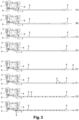
- step 3 The different stages of operation of the water injection system 1 are shown in figure 3 (steps A to H).
- pump 3 and injection line 5 are empty (A).
- the gases that were present in the injection line 5 exit from it at the level of the ejector 4. Once the water reaches the level of the ejector 4, it is ejected out of the injection line 5 by it (C, D).
- pump 3 is stopped and the water is no longer ejected from injection line 5 (E).
- the water remaining in the injection line 5 then begins to be purged.
- This air includes contaminants 9 such as bacteria or organic molecules.
- the water is conducted from the injection line 5 to the purge line 6 via the connector 7 and therefore via the sleeve 8.
- this sleeve 8 is made of copper.
- the sleeve 8 thus has a biocidal activity.
- contaminants can in particular be microorganisms such as bacteria, fungi or algae.
- the biocidal activity of the copper of the sleeve 8 prevents the microorganisms from forming a biofilm on the internal surface 8 of the sleeve.
- the biocidal activity of the copper of the sleeve 8 means that, even if the microorganisms manage to adhere to the internal surface of the sleeve 8, they do not have time to proliferate or secrete a matrix subsequently forming a biofilm before being destroyed by the copper. The obstruction of the device is thus avoided.
- the water which passes through the connector 7 and therefore through the sleeve 8 is thus decontaminated at least in part from the contaminants 9 which were contained in the air and which have spread and developed in the water (G, H). In this way, the water which returns to the tank 2 contains little or no microorganisms, for example bacteria, still capable of developing and potentially damaging the system.
- the device according to the invention for an aqueous solution other than water, for example for an aqueous solution comprising a mixture of water and ethanol.
Landscapes
- Engineering & Computer Science (AREA)
- Water Supply & Treatment (AREA)
- Chemical & Material Sciences (AREA)
- Combustion & Propulsion (AREA)
- General Engineering & Computer Science (AREA)
- Mechanical Engineering (AREA)
- Environmental & Geological Engineering (AREA)
- Health & Medical Sciences (AREA)
- Public Health (AREA)
- Organic Chemistry (AREA)
- Life Sciences & Earth Sciences (AREA)
- Hydrology & Water Resources (AREA)
- Agricultural Chemicals And Associated Chemicals (AREA)
- Apparatus For Disinfection Or Sterilisation (AREA)
- Jet Pumps And Other Pumps (AREA)
Claims (11)
- Einspritzsystem (1) für eine wässrige Lösung eines Fahrzeugs, aufweisend- einen Behälter (2) für die wässrige Lösung aus Kunststoff,- eine Einspritzpumpe (3),- einen Ejektor (4) für die wässrige Lösung,- eine Einspritzleitung (5), die sich zwischen der Pumpe und dem Ejektor befindet,- eine Entlüftungsleitung (6), die sich zwischen der Einspritzleitung und dem Behälter für die wässrige Lösung befindet, und- einen Auslassverbindungsstück (7), der sich zwischen der Einspritzleitung (5) und der Entlüftungsleitung (6) befindet, wobei das Verbindungsstück eine Außenseite und eine Innenseite aufweist und eine Antiverstopfungsvorrichtung bildet, die geeignet ist, die Bildung eines Biofilms zu begrenzen oder zu verhindern, wobei mindestens ein Teil der Innenseite des Verbindungsstücks aus einem Metall oder einem Material, das ein Metall enthält, hergestellt oder damit bedeckt ist, wobei das Metall ausgewählt ist aus Kupfer, Silber, Zink, Aluminium, Nickel, Gold, Barium, Blei, Zinn, Bor, Thallium, Antimon, Kobalt, Zirkonium, Molybdän, Titan, Eisen, Chrom und einer Legierung aus mindestens zwei dieser Metalle,wobei das System gekennzeichnet ist durch eine Hülse (8), die aus dem Metall oder aus dem das Metall aufweisenden Material hergestellt ist, die in das Verbindungsstück (7) eingesetzt ist und den Abschnitt oder die gesamte Innenseite des Verbindungsstücks bildet.
- Einspritzsystem (1) für eine wässrige Lösung eines Fahrzeugs nach Anspruch 1, wobei das Metall aus Kupfer, Silber und Zink ausgewählt ist.
- Einspritzsystem (1) für eine wässrige Lösung eines Fahrzeugs nach einem der vorhergehenden Ansprüche, wobei die gesamte Innenseite des Verbindungsstücks (7) aus dem Metall oder dem das Metall aufweisenden Material hergestellt ist.
- Einspritzsystem (1) für eine wässrige Lösung eines Fahrzeugs nach einem der vorhergehenden Ansprüche, wobei das Metall ein erstes Metall ist, das Verbindungsstück (7) einen Körper aus einem zweiten Metall aufweist, wobei der Körper auf mindestens einem Teil einer Innenfläche desselben mit dem ersten Metall bedeckt ist, wobei das erste Metall mindestens einen Teil der Innenfläche des Verbindungsstücks bildet.
- Einspritzsystem (1) für eine wässrige Lösung eines Fahrzeugs nach einem der vorhergehenden Ansprüche, wobei das Verbindungsstück (7) einen Nippel oder eine Muffe bildet.
- Einspritzsystem (1) für eine wässrige Lösung eines Fahrzeugs nach einem der vorhergehenden Ansprüche, wobei das Material, das ein Metall aufweist, 60 Gew.-% bis 95 Gew.-% Kupfer, 3 Gew.-% bis 45 Gew.-% Zink oder 90 Gew.-% bis 99 Gew.-% Silber aufweist.
- Einspritzsystem (1) für eine wässrige Lösung eines Fahrzeugs nach einem der vorhergehenden Ansprüche, wobei das Material, das ein Metall aufweist, eine Wärmeleitfähigkeit von mehr als 0,5 W.m-1.K-1 bei 20°C hat.
- Einspritzsystem (1) für eine wässrige Lösung eines Fahrzeugs nach einem der vorhergehenden Ansprüche, wobei das ein Metall aufweisend Material eine Polymermatrix aufweist, in der das Metall als Füllstoff dispergiert ist.
- Einspritzsystem (1) für eine wässrige Lösung eines Fahrzeugs nach einem der vorhergehenden Ansprüche, wobei das Material, das ein Metall aufweist, einen rostfreien Stahl oder eine Legierung aufweist, die einen rostfreien Stahl aufweist.
- Einspritzsystem (1) für eine wässrige Lösung eines Fahrzeugs nach einem der vorhergehenden Ansprüche, wobei die wässrige Lösung Wasser ist.
- Fahrzeug mit einem Einspritzsystem (1) für eine wässrige Lösung nach einem der Ansprüche 1 bis 10.
Applications Claiming Priority (2)
| Application Number | Priority Date | Filing Date | Title |
|---|---|---|---|
| FR1850932A FR3077602B1 (fr) | 2018-02-05 | 2018-02-05 | Systeme d'injection de solution aqueuse pour vehicule |
| PCT/EP2019/052754 WO2019149956A1 (fr) | 2018-02-05 | 2019-02-05 | Système d'injection de solution aqueuse pour véhicule |
Publications (3)
| Publication Number | Publication Date |
|---|---|
| EP3749846A1 EP3749846A1 (de) | 2020-12-16 |
| EP3749846C0 EP3749846C0 (de) | 2024-10-16 |
| EP3749846B1 true EP3749846B1 (de) | 2024-10-16 |
Family
ID=61802195
Family Applications (1)
| Application Number | Title | Priority Date | Filing Date |
|---|---|---|---|
| EP19705129.5A Active EP3749846B1 (de) | 2018-02-05 | 2019-02-05 | Einspritzsystem wässeriger lösung für fahrzeug |
Country Status (3)
| Country | Link |
|---|---|
| EP (1) | EP3749846B1 (de) |
| FR (1) | FR3077602B1 (de) |
| WO (1) | WO2019149956A1 (de) |
Family Cites Families (7)
| Publication number | Priority date | Publication date | Assignee | Title |
|---|---|---|---|---|
| TW444060B (en) | 1998-06-05 | 2001-07-01 | Kawasaki Steel Co | Stainless steel product having excellent antimicrobial activity and method for production thereof |
| DE10217649A1 (de) * | 2002-04-19 | 2004-01-08 | Stadelmann, Heinz W., Dr. | Entkeimungssystem, insbesondere zur Entkeimung von Trink- und Brauchwasser sowie Herstellung und Verwendung des Entkeimungssystems |
| US20080110812A1 (en) * | 2006-11-13 | 2008-05-15 | Mahle Tennex Industries, Inc. | Separated water treatment system for diesel fuel engine |
| WO2010119116A2 (en) * | 2009-04-16 | 2010-10-21 | Inergy Automotive Systems Research (Société Anonyme) | System and process for storing an additive and injecting it into the exhaust gases of an engine |
| WO2013075832A1 (en) * | 2011-11-25 | 2013-05-30 | Aua Ehf. | Apparatus for treating a mixture of fossil fuel and water prior to combustion in combustion engines |
| US20130327419A1 (en) * | 2012-02-22 | 2013-12-12 | Applied Silver, Inc. | Antimicrobial device |
| DE102015208477A1 (de) * | 2015-05-07 | 2016-11-10 | Robert Bosch Gmbh | Vorrichtung und Verfahren zur Einspritzung von Wasser einer Brennkraftmaschine |
-
2018
- 2018-02-05 FR FR1850932A patent/FR3077602B1/fr active Active
-
2019
- 2019-02-05 EP EP19705129.5A patent/EP3749846B1/de active Active
- 2019-02-05 WO PCT/EP2019/052754 patent/WO2019149956A1/fr not_active Ceased
Also Published As
| Publication number | Publication date |
|---|---|
| FR3077602B1 (fr) | 2021-01-15 |
| FR3077602A1 (fr) | 2019-08-09 |
| EP3749846A1 (de) | 2020-12-16 |
| EP3749846C0 (de) | 2024-10-16 |
| WO2019149956A1 (fr) | 2019-08-08 |
Similar Documents
| Publication | Publication Date | Title |
|---|---|---|
| FR2905161A1 (fr) | Raccord avec element chauffant integre. | |
| EP1597509A1 (de) | Sanierungsschale für hochdruckleitungen | |
| EP2717987B1 (de) | Flüssigkeitsfilter und maschinenbaugruppe als träger zur befestigung eines filtergehäuses | |
| FR2921455A1 (fr) | Systeme pour engrenage avec lubrification. | |
| FR2701895A1 (fr) | Plaque de busette et son procédé de traitement de surface. | |
| EP3079792A1 (de) | Kraftstofffilter mit additivausgabevorrichtung | |
| EP3749846B1 (de) | Einspritzsystem wässeriger lösung für fahrzeug | |
| EP0843124B1 (de) | Verfahren zum Transport eines Fluids in einer Rohrleitung die porige Struktur enthält | |
| FR2864169A1 (fr) | Filtre a carburant a evacuation d'eau facilitee | |
| WO2011138514A2 (fr) | Réservoir de fluide avec bol de réserve chauffant | |
| WO2011124770A1 (fr) | Réservoir de fluide avec système de mise à l'air | |
| FR3053081A1 (fr) | Circuit de depollution a uree comprenant un clapet a double siege assurant selectivement le degazage ou la recirculation de la solution aqueuse d’uree | |
| FR2992695A1 (fr) | Pompe a jet integrant un module de filtre | |
| FR2775326A1 (fr) | Clapet de non-retour et soupape a siege | |
| FR3060666A1 (fr) | Conduit de passage de liquide de refroidissement pour moteur a combustion interne de vehicule automobile | |
| FR3016413A1 (fr) | Systeme de protection thermique pour un reservoir cryogenique d'engin spatial | |
| FR2888289A1 (fr) | Dispositif d'injection d'additif liquide dans le circuit d'alimentation en carburant d'un moteur a combustion interne de vehicule automobile | |
| FR2974778A1 (fr) | Circuit de distribution de liquide lave-glace pour vehicule automobile et procede de protection d'un tel circuit. | |
| FR3065273A1 (fr) | Procede de fixation d'un element d'ancrage sur un element d'armure d'une conduite flexible, conduite et methode de montage associees | |
| EP0015193A1 (de) | Verbesserter Flüssigkeitstank | |
| EP2213858B1 (de) | Vorrichtung zum Wiederaufwärmen der Scheibenwischflüssigkeit eines Kraftfahrzeugs | |
| FR2901599A1 (fr) | Echangeur de chaleur, notamment pour le refroidissement des gaz d'echappement d'un vehicule | |
| EP3149320B1 (de) | Schwerkraftbasierender abscheidungsbehälter für einen flüssigkeitskreislauf | |
| FR3062710A1 (fr) | Rechauffeur de fluide corrosif pour metaux, reservoir et procede de fabrication associes. | |
| EP3803074B1 (de) | System zur speicherung einer wässrigen lösung für ein kraftfahrzeug |
Legal Events
| Date | Code | Title | Description |
|---|---|---|---|
| STAA | Information on the status of an ep patent application or granted ep patent |
Free format text: STATUS: UNKNOWN |
|
| STAA | Information on the status of an ep patent application or granted ep patent |
Free format text: STATUS: THE INTERNATIONAL PUBLICATION HAS BEEN MADE |
|
| PUAI | Public reference made under article 153(3) epc to a published international application that has entered the european phase |
Free format text: ORIGINAL CODE: 0009012 |
|
| STAA | Information on the status of an ep patent application or granted ep patent |
Free format text: STATUS: REQUEST FOR EXAMINATION WAS MADE |
|
| 17P | Request for examination filed |
Effective date: 20200905 |
|
| AK | Designated contracting states |
Kind code of ref document: A1 Designated state(s): AL AT BE BG CH CY CZ DE DK EE ES FI FR GB GR HR HU IE IS IT LI LT LU LV MC MK MT NL NO PL PT RO RS SE SI SK SM TR |
|
| AX | Request for extension of the european patent |
Extension state: BA ME |
|
| DAV | Request for validation of the european patent (deleted) | ||
| DAX | Request for extension of the european patent (deleted) | ||
| STAA | Information on the status of an ep patent application or granted ep patent |
Free format text: STATUS: EXAMINATION IS IN PROGRESS |
|
| 17Q | First examination report despatched |
Effective date: 20221108 |
|
| P01 | Opt-out of the competence of the unified patent court (upc) registered |
Effective date: 20230515 |
|
| GRAP | Despatch of communication of intention to grant a patent |
Free format text: ORIGINAL CODE: EPIDOSNIGR1 |
|
| STAA | Information on the status of an ep patent application or granted ep patent |
Free format text: STATUS: GRANT OF PATENT IS INTENDED |
|
| INTG | Intention to grant announced |
Effective date: 20240527 |
|
| GRAS | Grant fee paid |
Free format text: ORIGINAL CODE: EPIDOSNIGR3 |
|
| GRAA | (expected) grant |
Free format text: ORIGINAL CODE: 0009210 |
|
| STAA | Information on the status of an ep patent application or granted ep patent |
Free format text: STATUS: THE PATENT HAS BEEN GRANTED |
|
| AK | Designated contracting states |
Kind code of ref document: B1 Designated state(s): AL AT BE BG CH CY CZ DE DK EE ES FI FR GB GR HR HU IE IS IT LI LT LU LV MC MK MT NL NO PL PT RO RS SE SI SK SM TR |
|
| REG | Reference to a national code |
Ref country code: GB Ref legal event code: FG4D Free format text: NOT ENGLISH |
|
| REG | Reference to a national code |
Ref country code: CH Ref legal event code: EP |
|
| REG | Reference to a national code |
Ref country code: IE Ref legal event code: FG4D Free format text: LANGUAGE OF EP DOCUMENT: FRENCH |
|
| REG | Reference to a national code |
Ref country code: DE Ref legal event code: R096 Ref document number: 602019060432 Country of ref document: DE |
|
| U01 | Request for unitary effect filed |
Effective date: 20241114 |
|
| P04 | Withdrawal of opt-out of the competence of the unified patent court (upc) registered |
Free format text: CASE NUMBER: APP_66591/2024 Effective date: 20241216 |
|
| U07 | Unitary effect registered |
Designated state(s): AT BE BG DE DK EE FI FR IT LT LU LV MT NL PT RO SE SI Effective date: 20241219 |
|
| U20 | Renewal fee for the european patent with unitary effect paid |
Year of fee payment: 7 Effective date: 20250227 |
|
| PG25 | Lapsed in a contracting state [announced via postgrant information from national office to epo] |
Ref country code: HR Free format text: LAPSE BECAUSE OF FAILURE TO SUBMIT A TRANSLATION OF THE DESCRIPTION OR TO PAY THE FEE WITHIN THE PRESCRIBED TIME-LIMIT Effective date: 20241016 Ref country code: IS Free format text: LAPSE BECAUSE OF FAILURE TO SUBMIT A TRANSLATION OF THE DESCRIPTION OR TO PAY THE FEE WITHIN THE PRESCRIBED TIME-LIMIT Effective date: 20250216 |
|
| PG25 | Lapsed in a contracting state [announced via postgrant information from national office to epo] |
Ref country code: ES Free format text: LAPSE BECAUSE OF FAILURE TO SUBMIT A TRANSLATION OF THE DESCRIPTION OR TO PAY THE FEE WITHIN THE PRESCRIBED TIME-LIMIT Effective date: 20241016 |
|
| PG25 | Lapsed in a contracting state [announced via postgrant information from national office to epo] |
Ref country code: NO Free format text: LAPSE BECAUSE OF FAILURE TO SUBMIT A TRANSLATION OF THE DESCRIPTION OR TO PAY THE FEE WITHIN THE PRESCRIBED TIME-LIMIT Effective date: 20250116 |
|
| PG25 | Lapsed in a contracting state [announced via postgrant information from national office to epo] |
Ref country code: GR Free format text: LAPSE BECAUSE OF FAILURE TO SUBMIT A TRANSLATION OF THE DESCRIPTION OR TO PAY THE FEE WITHIN THE PRESCRIBED TIME-LIMIT Effective date: 20250117 |
|
| PG25 | Lapsed in a contracting state [announced via postgrant information from national office to epo] |
Ref country code: PL Free format text: LAPSE BECAUSE OF FAILURE TO SUBMIT A TRANSLATION OF THE DESCRIPTION OR TO PAY THE FEE WITHIN THE PRESCRIBED TIME-LIMIT Effective date: 20241016 |
|
| PG25 | Lapsed in a contracting state [announced via postgrant information from national office to epo] |
Ref country code: RS Free format text: LAPSE BECAUSE OF FAILURE TO SUBMIT A TRANSLATION OF THE DESCRIPTION OR TO PAY THE FEE WITHIN THE PRESCRIBED TIME-LIMIT Effective date: 20250116 |
|
| PG25 | Lapsed in a contracting state [announced via postgrant information from national office to epo] |
Ref country code: SM Free format text: LAPSE BECAUSE OF FAILURE TO SUBMIT A TRANSLATION OF THE DESCRIPTION OR TO PAY THE FEE WITHIN THE PRESCRIBED TIME-LIMIT Effective date: 20241016 |
|
| RAP4 | Party data changed (patent owner data changed or rights of a patent transferred) |
Owner name: OPMOBILITY C-POWER BELGIUM RESEARCH |
|
| U1H | Name or address of the proprietor changed after the registration of the unitary effect |
Owner name: OPMOBILITY C-POWER BELGIUM RESEARCH; BE |
|
| PG25 | Lapsed in a contracting state [announced via postgrant information from national office to epo] |
Ref country code: SK Free format text: LAPSE BECAUSE OF FAILURE TO SUBMIT A TRANSLATION OF THE DESCRIPTION OR TO PAY THE FEE WITHIN THE PRESCRIBED TIME-LIMIT Effective date: 20241016 |
|
| PG25 | Lapsed in a contracting state [announced via postgrant information from national office to epo] |
Ref country code: CZ Free format text: LAPSE BECAUSE OF FAILURE TO SUBMIT A TRANSLATION OF THE DESCRIPTION OR TO PAY THE FEE WITHIN THE PRESCRIBED TIME-LIMIT Effective date: 20241016 |
|
| PLBE | No opposition filed within time limit |
Free format text: ORIGINAL CODE: 0009261 |
|
| STAA | Information on the status of an ep patent application or granted ep patent |
Free format text: STATUS: NO OPPOSITION FILED WITHIN TIME LIMIT |
|
| PG25 | Lapsed in a contracting state [announced via postgrant information from national office to epo] |
Ref country code: MC Free format text: LAPSE BECAUSE OF FAILURE TO SUBMIT A TRANSLATION OF THE DESCRIPTION OR TO PAY THE FEE WITHIN THE PRESCRIBED TIME-LIMIT Effective date: 20241016 |
|
| 26N | No opposition filed |
Effective date: 20250717 |
|
| REG | Reference to a national code |
Ref country code: CH Ref legal event code: PL |
|
| PG25 | Lapsed in a contracting state [announced via postgrant information from national office to epo] |
Ref country code: CH Free format text: LAPSE BECAUSE OF NON-PAYMENT OF DUE FEES Effective date: 20250228 |
|
| GBPC | Gb: european patent ceased through non-payment of renewal fee |
Effective date: 20250205 |
|
| PG25 | Lapsed in a contracting state [announced via postgrant information from national office to epo] |
Ref country code: GB Free format text: LAPSE BECAUSE OF NON-PAYMENT OF DUE FEES Effective date: 20250205 |
|
| PG25 | Lapsed in a contracting state [announced via postgrant information from national office to epo] |
Ref country code: IE Free format text: LAPSE BECAUSE OF NON-PAYMENT OF DUE FEES Effective date: 20250205 |