EP3749816B1 - Formwork system - Google Patents
Formwork system Download PDFInfo
- Publication number
- EP3749816B1 EP3749816B1 EP19751109.0A EP19751109A EP3749816B1 EP 3749816 B1 EP3749816 B1 EP 3749816B1 EP 19751109 A EP19751109 A EP 19751109A EP 3749816 B1 EP3749816 B1 EP 3749816B1
- Authority
- EP
- European Patent Office
- Prior art keywords
- support
- upstanding member
- formwork system
- inclined portion
- central upstanding
- Prior art date
- Legal status (The legal status is an assumption and is not a legal conclusion. Google has not performed a legal analysis and makes no representation as to the accuracy of the status listed.)
- Active
Links
Images














Classifications
-
- E—FIXED CONSTRUCTIONS
- E04—BUILDING
- E04G—SCAFFOLDING; FORMS; SHUTTERING; BUILDING IMPLEMENTS OR AIDS, OR THEIR USE; HANDLING BUILDING MATERIALS ON THE SITE; REPAIRING, BREAKING-UP OR OTHER WORK ON EXISTING BUILDINGS
- E04G11/00—Forms, shutterings, or falsework for making walls, floors, ceilings, or roofs
- E04G11/36—Forms, shutterings, or falsework for making walls, floors, ceilings, or roofs for floors, ceilings, or roofs of plane or curved surfaces end formpanels for floor shutterings
- E04G11/38—Forms, shutterings, or falsework for making walls, floors, ceilings, or roofs for floors, ceilings, or roofs of plane or curved surfaces end formpanels for floor shutterings for plane ceilings of concrete
-
- E—FIXED CONSTRUCTIONS
- E04—BUILDING
- E04G—SCAFFOLDING; FORMS; SHUTTERING; BUILDING IMPLEMENTS OR AIDS, OR THEIR USE; HANDLING BUILDING MATERIALS ON THE SITE; REPAIRING, BREAKING-UP OR OTHER WORK ON EXISTING BUILDINGS
- E04G11/00—Forms, shutterings, or falsework for making walls, floors, ceilings, or roofs
- E04G11/36—Forms, shutterings, or falsework for making walls, floors, ceilings, or roofs for floors, ceilings, or roofs of plane or curved surfaces end formpanels for floor shutterings
- E04G11/48—Supporting structures for shutterings or frames for floors or roofs
- E04G11/486—Dropheads supporting the concrete after removal of the shuttering; Connecting means on beams specially adapted for dropheads
-
- E—FIXED CONSTRUCTIONS
- E04—BUILDING
- E04G—SCAFFOLDING; FORMS; SHUTTERING; BUILDING IMPLEMENTS OR AIDS, OR THEIR USE; HANDLING BUILDING MATERIALS ON THE SITE; REPAIRING, BREAKING-UP OR OTHER WORK ON EXISTING BUILDINGS
- E04G11/00—Forms, shutterings, or falsework for making walls, floors, ceilings, or roofs
- E04G11/36—Forms, shutterings, or falsework for making walls, floors, ceilings, or roofs for floors, ceilings, or roofs of plane or curved surfaces end formpanels for floor shutterings
- E04G11/48—Supporting structures for shutterings or frames for floors or roofs
- E04G11/50—Girders, beams, or the like as supporting members for forms
-
- E—FIXED CONSTRUCTIONS
- E04—BUILDING
- E04G—SCAFFOLDING; FORMS; SHUTTERING; BUILDING IMPLEMENTS OR AIDS, OR THEIR USE; HANDLING BUILDING MATERIALS ON THE SITE; REPAIRING, BREAKING-UP OR OTHER WORK ON EXISTING BUILDINGS
- E04G17/00—Connecting or other auxiliary members for forms, falsework structures, or shutterings
- E04G17/005—Strips for covering joints between form sections, e.g. to avoid burring or spilling of laitance
Definitions
- a formwork system for supporting forming panels to form a horizontal concrete surface.
- Formwork systems provide a temporary mold into / onto which liquid concrete can be poured. After the liquid concrete sets, the formwork may be removed, leaving behind a concrete structure.
- Formwork systems are used in building numerous types of structures, including buildings, bridges, parking garages, and so forth.
- Formwork systems may be used to form vertical concrete structures as well as horizontal concrete surfaces.
- Formwork systems may also be used to form inclined surfaces, for example, by inclining the beams.
- Inclined surfaces are useful in many applications, for example, to form ramps in parking garages.
- EP 3 112 556 A1 discloses a supporting device of the falling head type for supporting beams of formwork for floor slabs.
- the supporting device comprises a post to be fixed to the end of a supporting prop rested on the ground and a supporting head, coupled to the post for at least one supporting beam of formwork for floor slabs.
- the supporting head comprises two plates arranged mirror-symmetrically adjacent to opposite sides of the post and adapted to delimit laterally two accommodation regions of the ends of two supporting beams. At least two pairs of recesses are provided with respect to each other at different heights to form guides for the resting portions of the respective supporting beams to be installed at different heights from the ground.
- DE 42 04 788 A1 discloses a head bearing on a formwork support for a slab formwork with receptacles for parts of the slab formwork.
- the head bearing has receptacles separate from one another for formwork panels and for beams of the slab formwork, the receptacles being arranged in such a way that a uniform formwork surface is obtained.
- WO 2006/100694 A1 discloses a falling head support device for supporting beams of formworks for floors.
- the device comprises an upright which can be fixed at its end to a supporting strut that rests on the ground.
- a supporting head for at least one beam for supporting a formwork for floors is coupled so that it can slide along the upright.
- the support head comprises two plates which are arranged mirror-symmetrically so that they are laterally adjacent to opposite sides of the upright and are suitable to delimit laterally a region for accommodation the end of the at least one supporting beam.
- At least two recesses are provided for guiding the insertion and containment of a supporting portion of the corresponding supporting beam, each recess being provided on a respective plate, the bottom of each recess forming at least part of the supporting surface of the supporting portion of the supporting beam.
- a transverse element for connection the two plates is provided, which is suitable to support temporarily an inclined lower portion of the supporting beam during the setup and removal of the formwork of the beam.
- a formwork system for supporting one or more forming panels to form a horizontal concrete surface.
- the system includes: a height-adjustable support comprising a central upstanding member providing a vertical abutment surface and a support arm having an inclined portion extending up and away from the central upstanding member; a beam comprising a transverse bar proximate an end, the transverse bar supported by the inclined portion of the support arm so that the transverse bar moves laterally relative to the inclined portion as the support arm is moved vertically; and a foot extending from the end of said beam and abutting the vertical abutment surface, wherein the vertical abutment surface opposes lateral movement of the beam relative to said upstanding member.
- An increase in the height of said support causes the transverse bar to move towards the central upstanding member along the inclined portion.
- An incline angle of the beam is adjustable by adjusting the height of the support.
- a decrease in the height of said support causes the transverse bar to move away from the central upstanding member along the inclined portion.
- Forming panels are typically laterally secured to beams of the formwork system to prevent the beams from sliding along the beams.
- the lateral position of forming panels along the beams cannot be adjusted when beams are inclined. There may be large gaps between some forming panels and small gaps between other forming panels. Such systems are therefore ill suited for forming inclined surfaces.
- forming panels may be laterally unsecured to the beams to accommodate the use of a formwork system to form inclined surfaces.
- a worker can thus adjust the lateral position of the forming panels along the beams to accommodate the inclined beams to maintain panel gaps at a substantially constant size.
- laterally unsecured forming panels create a safety hazard as workers may walk on top of the forming panels from time-to-time. If a forming panel slides as a worker steps on the panel, the worker may fall and sustain an injury.
- the formwork system includes a height-adjustable support for supporting a beam in substantially horizontal position.
- the support includes a central upstanding member and a support arm.
- the support arm has an inclined portion extending up and away from the central upstanding member.
- the beam has a transverse bar, which is supported by the inclined portion of the support arm. As the support moves vertically, the transverse bar moves laterally relative to the inclined portion. A foot at the beam abuts the central upstanding member and opposes lateral movement of the beam relative to the upstanding member when the support is stationary.
Landscapes
- Engineering & Computer Science (AREA)
- Architecture (AREA)
- Mechanical Engineering (AREA)
- Civil Engineering (AREA)
- Structural Engineering (AREA)
- Forms Removed On Construction Sites Or Auxiliary Members Thereof (AREA)
Description
- This application claims priority from
Canadian Patent Application No. 2,994,076 filed February 6, 2018 . - A formwork system for supporting forming panels to form a horizontal concrete surface.
- Formwork systems provide a temporary mold into / onto which liquid concrete can be poured. After the liquid concrete sets, the formwork may be removed, leaving behind a concrete structure. Formwork systems are used in building numerous types of structures, including buildings, bridges, parking garages, and so forth.
- Formwork systems may be used to form vertical concrete structures as well as horizontal concrete surfaces. Formwork systems may also be used to form inclined surfaces, for example, by inclining the beams. Inclined surfaces are useful in many applications, for example, to form ramps in parking garages.
- However, traditional formwork systems are ill-suited for forming inclined surfaces. One problem with traditional formwork system is that gaps may form between forming panels. For example, a forming panel suspended by a first beam may not touch a forming panel suspended on an adjacent beam. Such gaps between panels are typically filled with thin strips that span the width of the forming panels (also known as 'compensation-strips').
EP 3 112 556 A1 discloses a supporting device of the falling head type for supporting beams of formwork for floor slabs. The supporting device comprises a post to be fixed to the end of a supporting prop rested on the ground and a supporting head, coupled to the post for at least one supporting beam of formwork for floor slabs. The supporting head comprises two plates arranged mirror-symmetrically adjacent to opposite sides of the post and adapted to delimit laterally two accommodation regions of the ends of two supporting beams. At least two pairs of recesses are provided with respect to each other at different heights to form guides for the resting portions of the respective supporting beams to be installed at different heights from the ground.
DE 42 04 788 A1 discloses a head bearing on a formwork support for a slab formwork with receptacles for parts of the slab formwork. The head bearing has receptacles separate from one another for formwork panels and for beams of the slab formwork, the receptacles being arranged in such a way that a uniform formwork surface is obtained.WO 2006/100694 A1 discloses a falling head support device for supporting beams of formworks for floors. The device comprises an upright which can be fixed at its end to a supporting strut that rests on the ground. A supporting head for at least one beam for supporting a formwork for floors is coupled so that it can slide along the upright. The support head comprises two plates which are arranged mirror-symmetrically so that they are laterally adjacent to opposite sides of the upright and are suitable to delimit laterally a region for accommodation the end of the at least one supporting beam. At least two recesses are provided for guiding the insertion and containment of a supporting portion of the corresponding supporting beam, each recess being provided on a respective plate, the bottom of each recess forming at least part of the supporting surface of the supporting portion of the supporting beam. A transverse element for connection the two plates is provided, which is suitable to support temporarily an inclined lower portion of the supporting beam during the setup and removal of the formwork of the beam. - Accordingly, improvements in formwork systems are desirable. This and other objects are achieved by a formwork system according to claim 1.
- In accordance with an aspect of the present disclosure, there is provided a formwork system for supporting one or more forming panels to form a horizontal concrete surface. The system includes: a height-adjustable support comprising a central upstanding member providing a vertical abutment surface and a support arm having an inclined portion extending up and away from the central upstanding member; a beam comprising a transverse bar proximate an end, the transverse bar supported by the inclined portion of the support arm so that the transverse bar moves laterally relative to the inclined portion as the support arm is moved vertically; and a foot extending from the end of said beam and abutting the vertical abutment surface, wherein the vertical abutment surface opposes lateral movement of the beam relative to said upstanding member. An increase in the height of said support causes the transverse bar to move towards the central upstanding member along the inclined portion. An incline angle of the beam is adjustable by adjusting the height of the support.
- In one embodiment, a decrease in the height of said support causes the transverse bar to move away from the central upstanding member along the inclined portion.
- Other aspects, features, and embodiments of the present disclosure will become apparent to those of ordinary skill in the art upon review of the following description of specific embodiments in conjunction with the accompanying figures.
- In the figures, which illustrate, by way of example only, embodiments of the present disclosure,
-
FIG. 1A is a top-perspective view of aformwork system 100 in accordance with an example embodiment; -
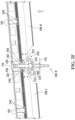
FIG. 1B is a side views offormwork system 100 in accordance with an example embodiment; -
FIG. 1C is a side view of a support for use with theformwork system 100 in accordance with an example embodiment; -
FIG. 1D is a side view of a beam for use with theformwork system 100 in accordance with an example embodiment; -
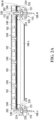
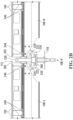
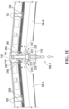
FIGS. 2A-2C and 2E-2F are close-up side views of theformwork system 100; -
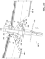
FIG. 2D is a side-perspective view of theformwork system 100; -
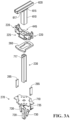
FIG. 3A is an exploded view of a support for use with theformwork system 100 in accordance with an example embodiment; -
FIG. 3B is an top view of a support ofFIG. 3A ; -
FIG. 3C is a side view of the support ofFIG. 3A ; -
FIG. 3D is a second side view of the support ofFIG. 3A ; -
FIG. 3E is a top-perspective view of the support ofFIG. 3A ; -
FIG. 4A is a top view of a support head for use with the support ofFIG. 3A in accordance with an example embodiment; -
FIG. 4B is a side view of the support head ofFIG. 4A ; -
FIG. 4C is a second side view of the support head ofFIG. 4A ; -
FIG. 4D is a top-perspective side view of the support head ofFIG. 4A ; -
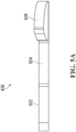
FIG. 5A is a top view of a side plate for use with the support head ofFIG. 4A in accordance with an example embodiment; -
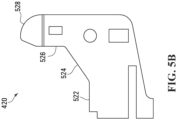
FIG. 5B is a side view of the side plate ofFIG. 5A ; -
FIG. 5C is a second side view of the side plate ofFIG. 5A ; -
FIG. 6A is a top view of a support element for use with the support ofFIG. 3A in accordance with an example embodiment; -
FIG. 6B is a side view of the support element ofFIG. 6A ; -
FIG. 6C is a bottom view of the support element ofFIG. 6A ; -
FIG. 6D is a second side view of the support element ofFIG. 6A ; -
FIG. 6E is a top-perspective view of the support element ofFIG. 6A ; -
FIG. 6F is partial close-up view of the support element ofFIG. 6A ; -
FIG. 7A is top view of a base plate for use with the support ofFIG. 3A in accordance with an example embodiment; -
FIG. 7B is a top view of a base portion for use with the support ofFIG. 3A in accordance with an example embodiment; -
FIGS. 7C-7E are side views of the base portion ofFIG. 7B ; -
FIG. 7F is a top-perspective view of the base portion ofFIG. 7B ; -
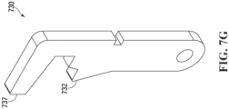
FIG. 7G is a top-perspective view of a hook for use with the base portion ofFIG. 7B in accordance with an example embodiment; -
FIG. 7H is a top-perspective view of a spring for use with the base portion ofFIG. 7B in accordance with an example embodiment; -
FIG. 8A is a side view of a release wedge for use with the support ofFIG. 3A in accordance with an example embodiment; -
FIG. 8B is a top view of the release wedge element ofFIG. 8A ; -
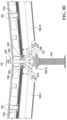
FIG. 8C is a cross-section view of the support element ofFIG. 8A ; -
FIG. 8D is a second side view of the support element ofFIG. 8A ; -
FIG. 8E is a close-up side view of theformwork system 100 in a second position in accordance with an example embodiment; -
FIG. 9A is a top-perspective view of a beam for use with theformwork system 100 in accordance with an example embodiment; -
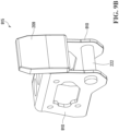
FIG. 9B is a top-perspective view of a saddle member for use with the beam ofFIG. 9A ; -
FIGS. 9C-9E are top, side, and bottom views of the beam ofFIG. 9A ; -
FIG. 9F is a close-up side view of an end of the beam ofFIG. 9A ; -
FIG. 9G is a side view of an end of the beam ofFIG. 9A ; -
FIG. 9H is a cross-section view of protrusions of the beam ofFIG. 9A ; -
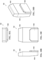
FIGS. 10A-10D are top, side, back, and top-perspective views of a foot of the beam ofFIG. 9A in accordance with an example embodiment; -
FIG. 11A is a top-perspective view of a compensation-strip for use with theformwork system 100 in accordance with an example embodiment; and -
FIGS. 11B-11D are side views of the compensation-strip ofFIG. 11A in use with theformwork system 100 in accordance with an example embodiments. - When formwork systems are used form inclined surfaces, different sized gaps may result between forming panels. Forming panels are typically laterally secured to beams of the formwork system to prevent the beams from sliding along the beams. The lateral position of forming panels along the beams cannot be adjusted when beams are inclined. There may be large gaps between some forming panels and small gaps between other forming panels. Such systems are therefore ill suited for forming inclined surfaces.
- Alternatively, forming panels may be laterally unsecured to the beams to accommodate the use of a formwork system to form inclined surfaces. A worker can thus adjust the lateral position of the forming panels along the beams to accommodate the inclined beams to maintain panel gaps at a substantially constant size. However, laterally unsecured forming panels create a safety hazard as workers may walk on top of the forming panels from time-to-time. If a forming panel slides as a worker steps on the panel, the worker may fall and sustain an injury.
- Disclosed is a formwork system adapted for forming concrete surfaces that transition from level to sloping (or vice-versa). In particular, the formwork system includes a height-adjustable support for supporting a beam in substantially horizontal position. The support includes a central upstanding member and a support arm. The support arm has an inclined portion extending up and away from the central upstanding member. The beam has a transverse bar, which is supported by the inclined portion of the support arm. As the support moves vertically, the transverse bar moves laterally relative to the inclined portion. A foot at the beam abuts the central upstanding member and opposes lateral movement of the beam relative to the upstanding member when the support is stationary.
- Thus, when the support arm moves up or down vertically, the beam moves both horizontally and vertically along the inclined portion. In turn, the lateral shift of the beam in response to vertical shift of the support is reduced. Thus, the variance in the gap between laterally secured forming panels is also reduced. As a result, a single type of compensation-strips having an adjustable width can be used with the system.
- Reference is made to
FIGS. 1A-1B , illustrating perspective and side views of aformwork system 100 for supporting one or more formingpanels 102. - Forming
panels 102 provide a flat surface to pour liquid concrete thereon. In one embodiment, a plywood panel is used to provide the flat surface. In one embodiment, formingpanels 102 may be 2 feet wide and 6 feet long. However, other sizes are possible: for example, formingpanels 102 may range from 1 foot to 6 feet in length or width. In addition, different sized formingpanels 102 may be used withformwork system 100. - In one embodiment, each plywood panel of a forming
panel 102 is supported by beams (not shown) extending along the edges of the panel. The plywood panel may also be supported by a series of beams spanning the length or width of the panel. The beams of a formingpanel 102 may be made of a light material, such as wood or aluminum. -
Formwork system 100 also includes a plurality ofsupports 105 and beams 108. Eachsupport 105 hasbase portion 104 and asupport head 106 at an upper portion ofsupport 105.Beams 108 are supported at each end bysupport head 106. In one embodiment,support head 106 is removably mounted on a vertical prop. - One or
more supports 105 ofsystem 100 may also support a compensation-strip 110. Compensation-strips 110 may be used to fillgaps 112 betweenpanels 102 that form around support heads 106. - In use, a first pair of supports 105 (for example, including a pair of support heads 106 and a pair of vertical props) may be used to suspend a
first beam 108. A second pair ofsupports 105 may be used to suspend asecond beam 108 in a substantially parallel position to thefirst beam 108. One or more formingpanels 102 may be supported on each of the first and second beams to form a suspended horizontal surface suitable for pouring concrete thereon. The horizontal surface formed bysystem 100 may have sections that are inclined and sections that are level. -
Additional beams 108, supports 105, and formingpanels 102 can be arranged side-by-side to form a larger suspended horizontal surface suitable for pouring concrete thereon. - As illustrated in
FIG. 1B ,formwork system 100 allows for forming leveled and inclined horizontal concrete surfaces. In addition,formwork system 100 may be used to form a single horizontal concrete surface that transitions between upward sloping and downward sloping. For example, as illustrated inFIG. 1B beam 108-1 and the panels associated therewith are sloping up relative to support head 106-1. Similarly, beam 108-2 and the panels associated therewith are sloping down from support head 106-2. Similarly, beam 108-3 and the panels associated therewith are sloping down from support head 106-3. Similarly, beam 108-4 and the panels associated therewith are sloping up relative to support head 106-4. Similarly, beam 108-5 and the panels associated therewith are level with support head 106-5. Beam 108-6 and the panels associated therewith also level. - The incline angle of a particular beam may be adjusted by adjusting the height of one of the
supports 105 supporting that particular beam (for example, by adjusting the height of one of or both ofsupport head 106 andvertical prop 104 supporting support head 106). As illustrated inFIG. 1B , the heights of supports 105-1 to 105-6 are varied (or base portion 104-1 to 104-5, for example, using height adjustable vertical props) to achieve the desired angle of each of beams 108-1 to 108-6. - In one embodiment, the maximum incline angle of a
beam 108 and the formingpanels 102 associated therewith is plus or minus 5 degrees relative to the horizontal. - Reference is made to
FIG. 1C illustrating anexample support 105 foruse formwork system 100 in accordance one embodiment.Support 105 has asupport head 106 havingsupport arms 220.Support head 106 and supportarms 220 thereof are supported in an elevated position bybase portion 104 ofsupport 105.Beams 108 are supported at each end bysupport arms 220 ofsupport head 106. -
Support arms 220 may be lowered or raised to vary the slope of beams supported by thesupport head 106. In one embodiment,support head 106 is mounted on a height-adjustable vertical prop, and the height ofsupport arms 220 is adjustable by adjusting the height of the vertical prop. In one embodiment,support head 106 hassupport arms 220 that are height-adjustable independently frombase portion 104. - As shown,
support 105 has twosupport arms 220 positioned on opposite sides ofsupport 105, but other embodiments are possible. For example, eachsupport 105 may have foursupport arms 220. -
Support arm 220 ofsupport 105 has aninclined portion 224 extending up and away from the center ofsupport head 106. In one embodiment,support arm 220 also has aflat portion 226 extending laterally from the center ofsupport head 106 andinclined portion 224 extends up and away fromflat portion 226.Inclined portion 224 has an angle of α degrees relative to the horizontal, which may in some embodiments range from 30 to 40 degrees. -
Support 105 also has a centralupstanding member 230 at the center ofsupport head 106. Centralupstanding member 230 extends vertically upwards relative to supportarms 220.Inclined portion 224 extends up and away from centralupstanding member 230. -
Beam 108 may abut centralupstanding member 230, and in turn, centralupstanding member 230 may oppose lateral movement ofbeam 108; thereby laterally stabilizingbeam 108. - Reference is made to
FIG. 1D illustrating a partial side view of anexample beam 108 for use withformwork system 100 in accordance one embodiment. - In one embodiment,
beam 108 has twoside plates 910 attached proximate an end of the beam and extending away from the beam. In one embodiment,side plates 910 secure atransverse bar 222 in a position proximate the end of the beam (seeFIGS. 9A-9B ). - In use,
transverse bar 222 may be supported byinclined portion 224 ofsupport arm 220 to suspendbeam 108. As will be explained further, the position oftransverse bar 222 alonginclined portion 224 may vary in dependence on the incline angle ofbeam 108 when suspended. - In one embodiment,
beam 108 also has afoot 202 extending from the end of the beam. In one embodiment,foot 202 is a small metallic block (for example, made of steel) attached to the end ofbeam 108. In one embodiment,foot 202 has thickness of 1 to 3 cm. In one embodiment,foot 202 is longer than the height of an end portion ofbeam 108, such thatfoot 202 may extend relative to the upper and lower surfaces of the end portion ofbeam 108. In one embodiment,foot 202 may be positioned substantially perpendicular tobeam 108. - In one embodiment,
foot 202 is positioned at the end-most portion ofbeam 108, such that a portion offoot 202 may abut central upstanding member 230 (FIG. 1C ), and in turn, may oppose lateral movement ofbeam 108 to laterally stabilizingbeam 108. - Accordingly, central
upstanding member 230 provides a vertical abutment surface forfoot 202 to oppose lateral movement ofbeam 108 relative to centralupstanding member 230. By abutting vertical abutment surface,foot 202 may preventtransverse bar 222 from moving laterally alonginclined portion 224. - In one embodiment,
foot 202 is any extension tobeam 108 that provides a suitable abutment surface to laterally stabilizebeam 108. - Reference is made to
FIGS. 2A and2B , illustrating beams 108-L, 108-R (generally referred to as "beams 108") and support heads 106-L, 106-R (generally referred to as "support heads 106"). Support heads 106 are each supported in an elevated position, for example by a vertical prop (not shown). - Beam 108-L is supported by
support arms 220 of support head 106-L at one end and bysupport arms 220 of support head 106-R at a second end in a level position. Beam 108-R is supported bysupport arms 220 of support head 106-R at one end and bysupport arms 220 of a second support head (not shown) at a second end (not shown) in a level position. - When
beam 108 is in a level / horizontal position,transverse bar 222 is supported approximately at the middle ofinclined portion 224 of support arm 220 (as shown in phantom inFIG. 2B ). Further,foot 202 is substantially perpendicular to centralupstanding member 230. - Each
beam 108 hasprotrusions 240 extending upwardly from an upper surface of the beam. Eachprotrusion 240 is configured to engage the lower surface of a formingpanel 102 to prevent lateral movement of the formingpanel 102 alongbeam 108. - Reference is made to
FIGS. 2C and2D , illustrating beams 108-L, 108-R and support head 106-R. InFIGS. 2C and2D ,support arm 220 of support head 106-R has been moved down vertically relative to its position inFIGS. 2A and2B ; thus, both beams 108-L, 108-R are sloping up relative to support head 106-R. Thebeams 108 now create a 'valley'. -
Support arm 220 ofsupport head 106 may be moved vertically downwards by adjusting the height of a vertical prop upon whichsupport head 106 is mounted. Alternatively,support arm 220 may be vertically movable relative to centralupstanding member 230. - The decrease in the height of support head 106-R also causes transverse bars 222 (shown in phantom) resting on
inclined portions 224 of support head 106-R to move laterally away from centralupstanding member 230 along theinclined portion 224. While inFIGS. 2A and2B (when the beams are level)transverse bar 222 is supported approximately at the middle ofinclined portion 224 ofsupport arm 220, inFIGS. 2C and2D (when the beams are sloping up),transverse bar 222 is supported near the top ofinclined portion 224 ofsupport arm 220 at the position furthest from centralupstanding member 230. - Furthermore, in
FIGS. 2C and2D ,foot 202 is no longer substantially perpendicular to centralupstanding member 230. InFIGS. 2C and2D , when beams 108-L, 108-R are sloping up relative to support head 106-R,foot 202 partially abuts centralupstanding member 230 such that only an upper portion offoot 202 abuts centralupstanding member 230. - In addition, the gap between forming
panels 102 supported by beam 108-L and formingpanels 102 supported by beam 108-R is relatively smaller whenbeams 108 are sloping up relative to support head 106-R (FIG. 2C ) compared to whenbeams 108 are level (FIGS. 2A and2B ). Notably, however, since the beams moved both laterally and vertically whensupport arm 220 was moved down, the difference in the gap size is reduced. - Reference is made to
FIG. 2E illustrating beams 108-L, 108-R and support head 106-R. InFIG. 2E ,support arm 220 of support head 106-R has been moved vertically upwards relative to its position inFIGS. 2A and2B ; thus, both beams 108-L, 108-R are sloping down relative to support head 106-R. Thebeams 108 now create a 'peak'. - Further the increase in the height of support head 106-R also causes transverse bars 222 (shown in phantom) resting on
inclined portions 224 ofsupport arm 220 to move laterally towards centralupstanding member 230 along theinclined portion 224. While inFIGS. 2A and2B (when the beams are level)transverse bar 222 is supported approximately at the middle ofinclined portion 224 ofsupport arm 220, inFIG. 2E (when the beams are sloping down),transverse bar 222 is supported near the bottom ofinclined portion 224 ofsupport arm 220 at the position closest to centralupstanding member 230. - Furthermore, in
FIG. 2E ,foot 202 is also no longer substantially perpendicular to centralupstanding member 230. InFIG. 2E , when beams 108-L, 108-R are sloping down from support head 106-R,foot 202 partially abuts centralupstanding member 230 such that only a lower portion offoot 202 abuts centralupstanding member 230. - In some embodiments, the abutment surface of lower portion of
foot 202 may be tapered (FIG. 9F ) such thatbeam 108 can move more closely towards centralupstanding member 230 when the beam is sloping down from support head 106-R. - In addition, the gap between forming
panels 102 supported by beam 108-L and formingpanels 102 supported by beam 108-R is relatively larger whenbeams 108 are sloping down relative to support head 106-R (FIG. 2E ) compared to whenbeams 108 are level (FIGS. 2A and2B ). Notably, however, since the beams moved both laterally and vertically whensupport arm 220 was moved up, the difference in the gap size is reduced. - Reference is made to
FIG. 2F illustrating beams 108-L, 108-R and support head 106-R. InFIG. 2F ,support arm 220 of support head 106-R is in the same vertical position as inFIG. 2E , but the second support head (not shown) supporting beam 108-R has been moved vertically upwards relative to its position inFIG. 2E . Thus, beam 108-L is sloping down from support head 106-R whereas beam 108-R is sloping up relative to support head 106-R. Thebeams 108 now create a 'ramp'. - Further, the increase in the height of the second support arm (not shown) also causes transverse bar 222 (shown in phantom) of beam 108-R resting on
inclined portions 224 of support head 106-R to move laterally away from centralupstanding member 230 along theinclined portion 224. While inFIG. 2E transverse bar 222 of beam 108-R is supported near the bottom ofinclined portion 224 of support arm 220 (at the position closest to central upstanding member 230), inFIG. 2F transverse bar 222 of beam 108-R is supported near the top ofinclined portion 224 of support arm 220 (at the position furthest from central upstanding member 230). - Furthermore, in
FIG. 2F , lower portion offoot 202 of beam 108-R is no longer abutting centralupstanding member 230. Instead, only upper portion offoot 202 of beam 108-R partially abuts centralupstanding member 230. - In addition, the gap between forming
panels 102 supported by beam 108-L and formingpanels 102 supported by beam 108-R is relatively smaller inFIG. 2F compared to inFIG. 2E . - Thus, an increase in the height of a
support arm 220 supporting atransverse bar 224 of abeam 108 results in lateral movement of thetransverse bar 222 along theinclined portion 224 of thesupport arm 220 towards centralupstanding member 230 and further results in lateral movement of thebeam 108 towards centralupstanding member 230. Further, any formingpanels 102 resting onbeam 108 which are laterally secured byprotrusions 240 will move laterally along withbeam 108. - Similarly, a decrease in the height of a
support arm 220 supporting atransverse bar 224 of abeam 108 results in lateral movement of thetransverse bar 222 along theinclined portion 224 of thesupport arm 220 away from centralupstanding member 230 and further results in lateral movement of thebeam 108 away from centralupstanding member 230. Further, any formingpanels 102 resting onbeam 108 which are laterally secured byprotrusions 240 will move laterally along withbeam 108. - In other words, each
support arm 220 offormwork system 100 acts as a shifting pivot point forbeams 108.Beam 108 moves laterally when pivoted about support arm 220 (in addition to moving vertically). Sincebeams 108 have a fixed length, pivoting one end of abeam 108 about a fixed point would result in a lateral shift of the opposite end ofbeam 108. However, informwork system 100beams 108 moves laterally when pivoted; thus, the lateral shift of the opposite end ofbeam 108 is reduced. - In one embodiment, an increase in the height of a
support arm 220 by approximately 200 to 220 mm will result in a lateral movement oftransverse bar 222 alonginclined portion 224 of thesupport arm 220 towards centralupstanding member 230 by approximately 9.5 mm. In addition,transverse bar 222 will move down vertically alonginclined portion 224 by approximately 4.5 mm. Further, the increase in height will causebeam 108 to incline down fromsupport head 106 at an angle of 5 degrees. - In one embodiment, a decrease in the height of a
support arm 220 by approximately 200 to 220 mm will result in a lateral movement of thetransverse bar 222 along theinclined portion 224 of thesupport arm 220 away from centralupstanding member 230 by approximately 7 mm. In addition,transverse bar 222 will move up vertically alonginclined portion 224 by approximately 7 mm. Further, the increase in height will causebeam 108 to incline up relative to supporthead 106 at an angle of 5 degrees. - Reference is now made to
FIGS. 3A-3E , showing an example embodiment ofsupport head 106 in isolation. As will be explained in greater detail,support head 106 has asupport arm block 225 including support arm(s) 220, abase portion 270 for mountingsupport head 106 on a vertical prop (not shown), arelease wedge 260 andside plates 265 allowingsupport head 106 to function as a 'drop-head' (as will be explained later), and anupper support 250 for supporting a compensation-strip 110. In one embodiment,support head 106 extends by approximately 500 mm from the top ofupper support 250 to the bottom ofbase portion 270. - Central
upstanding member 230 is an elongate member. For example, in one embodiment, centralupstanding member 230 is approximately 40 mm long, 40 mm wide and 340 mm tall. In one embodiment, centralupstanding member 230 is made of a metallic material, such as aluminum or steel. In one embodiment, centralupstanding member 230 is hollow. - In one embodiment, central
upstanding member 230 hasside plates 265 attached at a bottom portion thereof to increase the thickness of the bottom portion of centralupstanding member 230. In one embodiment, eachside plate 265 is 10 mm thick, thereby increasing the thickness of the bottom portion of centralupstanding member 230 to 60 mm. - One example embodiment of
support arm block 225 ofsupport head 106 is illustrated in isolation inFIGS. 4A-4D .Support arm block 225 has acentral block 445, formed by anupper base plate 440 and alower base plate 442 separated by avertical plates 444. Each ofupper base plate 440 andlower base plate 442 has a void in the center thereof.Support arm block 225 receives centralupstanding member 230 through the voids in upper andlower base plates FIGS. 3A-3E ). - In one embodiment, each of upper and
lower base plates upper base plate 440 is approximately 60 mm x 60 mm in size and the void oflower base plate 442 is approximately 60 mm x 41 mm in size. Further, in one embodiment, centralupstanding member 230 is marginally smaller in size than the void of lower base plate 442 (for example, 40 mm x 40 mm in size), such thatsupport arm block 225 can move vertically relative to centralupstanding member 230. - In one embodiment, the plates of
support arm block 225 are made of a metallic material, such as aluminum or steel. The plates may be secured to one another by welding. - In one embodiment,
support arm block 225 includes twosupport arms 220, mounted at opposing sides ofsupport arm block 225. In one embodiment, the distance between the twosupport arms 220 is approximately 200 mm. - Each
support arm 220 may include two opposingside plates 420, which are separated by upper andlower spacers side plates 420, when placed side-by-side, separated byspacers inclined portion 224 and flat portion 226 (FIG. 1C ) upon whichtransverse bar 222 ofbeam 108 may be supported. -
Side plates 420 and upper andlower spacers Side plates 420 may interlock withcentral block 445 ofsupport arm block 225. In one embodiment,side plates 420 may also be welded to upper andlower spacers central block 445. In one embodiment, supportarms 220 are welded tocentral block 445. - One example embodiment of a
side plate 420 ofsupport arm 220 ofsupport arm block 225 is illustrated in isolation inFIGS. 5A-5C . Notably, as shown, eachside plate 420 has a flat /horizontal portion 522 which extends away from central block 445 (and central upstanding member 230), aninclined portion 524 which extends up and away from flat /horizontal portion 522, and avertical portion 526 extending upwardly frominclined portion 524. - In one embodiment, flat /
horizontal portion 522 may limit the range of travel oftransverse bar 222, thereby making assembly offormwork system 100 more convenient. In one embodiment,flat portion 522 may extend 25 to 35 mm away fromcentral block 445. - As previously discussed,
inclined portion 524 provides theinclined portion 224 upon whichtransverse bar 222 ofbeam 108 is supported. In one embodiment, as shown,inclined portion 524 is a straight incline. Further, in one embodiment,inclined portion 524 may be inclined at an angle ranging from 30 to 40 degrees. As shown,inclined portion 524 is inclined at a 35 degree angle. Further, in one embodiment,inclined portion 524 may extend 25 to 35 mm away fromflat portion 522. - In one embodiment,
inclined portion 524 is approximately 30 mm in length. The length ofinclined portion 524 may be modified to alter the maximum incline angle ofbeams 108. In one embodiment, aninclined portion 524 allows the beams to incline up or down by 5 degrees. - In other embodiments, the inclined portion may be curved (not shown). For example, the inclined portion may take the shape of a quadratic which extends up and away from
flat portion 522. - In other embodiments, the inclined portion may be jagged (not shown). For example, the inclined portion may include multiple steps upon which
transverse bar 222 ofbeam 108 may be supported. Notably, however, a jagged inclined portion may be more difficult to use astransverse bar 222 may not slide easily up along the jagged inclined portion. -
Vertical portion 526 may be helpful in preventingtransverse bar 222 from rolling offinclined portion 524 when only one end ofbeam 108 is supported, and thus also preventsbeam 108 from falling. In one embodiment,vertical portion 526 extends up by 10 to 20 mm from the top ofinclined portion 524. - In one embodiment, each
side plate 420 also has atapered end 528 extending upwardly fromvertical portion 526.Tapered end 528 may have a tapered slope extending fromvertical portion 526, which may help directtransverse bar 222 towardsinclined portion 524 ofside plate 420. Further, in one embodiment, the outer edge oftapered end 528 may be curved to minimize sharp edges and reduce the likelihood of injury to a worker. - In some embodiments,
tapered end 528 has a width ranging from 20 to 30 mm and a height ranging from 15 to 22 mm. In some embodiments,tapered end 528 is also angled in towards the opposing side plate 420 (seeFIGS. 4C and5C ). In some embodiments,tapered end 528 is angled in at an angle ranging from 5 to 15 degrees (10 degrees, as shown). In one embodiment,tapered end 528 is angled by deforming a portion ofplate 420. - An example embodiment of
upper support 250 for supporting a compensation-strip 110 is shown in isolation inFIGS. 6A-6F .Upper support 250 is mounted at the top ofsupport head 106 such that when compensation-strip 110 is supported onupper support 250, compensation-strip 110 is level with formingpanels 102 adjacent to the compensation-strip 110. - In one embodiment, as shown in
FIGS. 6B, 6D, and 6E ,upper support 250 is T-shaped, having anupper cross-member 620, asupport plate 615 for supportingupper cross-member 620, and avertical member 610. In one embodiment, the components ofupper support 250 are made of a metallic material, such as aluminum or steel. - In one embodiment,
vertical member 610 is hollow and is larger in size thanupstanding member 230, such thatvertical member 610 maybe inserted over centralupstanding member 230, as shown inFIGS. 3A-3E . In one embodiment,vertical member 610 is approximately 70 mm long, 50 mm wide and 180 mm tall. In contrast, centralupstanding member 230 is smaller in size (for example, 40 mm x 40 mm in size). - In one embodiment,
vertical member 610 includes a through-hole 617 and centralupstanding member 230 includes a corresponding through-hole 717. Through-hole 617 and through-hole 717 are aligned whenvertical member 610 is inserted over centralupstanding member 230. To removably secure the two members to one another, a pin or screw (not shown) may be inserted into through-hole 617 ofvertical member 610 ofupper support 250 and into corresponding through-hole 717 (FIG. 3A ) of centralupstanding member 230. - In one embodiment,
support plate 615 is secured to the top of vertical member 610 (for example, by welding, with a screw, or otherwise).Support plate 615 has a width corresponding to the width ofupper cross-member 620, which is then secured to support plate 615 (for example, by welding, with a screw, or otherwise). In one embodiment,upper cross-member 620 has a width of 50 mm and is 240 mm long. - In one embodiment, once mounted,
upper cross-member 620 is the top point of support head 106 (FIG. 3A-3E ).Upper cross-member 620 is configured (for example, shaped) to support a central hinge portion of a compensation-strip 110. The central hinge portion of a compensation-strip 110 may rest onupper cross-member 620 without being secured thereto (FIGS. 11A-11D ). In one embodiment,upper cross-member 620 has a top surface that has a corresponding shape to the central hinge portion of compensation-strip 110. For example, the top surface ofupper cross-member 620 may be curved to accommodate the central hinge portion of compensation-strip 110. - Reference is made to
FIGS. 7A-7F , showing an example embodiment of abase portion 270 ofsupport head 106.Base portion 270 allows for mountingsupport head 106 on a vertical prop.Base portion 270 includes a base plate 710 (FIG. 7A ) for securingsupport head 106 to a vertical prop, a U-shaped member 720 (FIGS. 7C-7F ), and hinged hooks 730 (FIGS. 7C-7G ). In one embodiment, the components ofbase portion 270 are made of a metallic material, such as aluminum or steel. -
Base plate 710 may have a central void 715 (FIG. 7A ). In one embodiment,central void 715 is approximately 25 mm in width and 25 mm in length. - A bottom portion of central
upstanding member 230 may be secured to an upper side ofbase plate 710 atcentral void 715, for example, by welding. Similarly, the top ofU-shaped member 720 may be secured to a lower side ofbase plate 710 atcentral void 715, for example, by welding. -
Base plate 710 may also be shaped to prevent beams from hittingsupport 105 which supports the beam. As shown inFIG. 7A ,base plate 710 hasextension portions 721 on each side thereof. In use,extension portions 721 are aligned withbeams 108. Thus, when only one end ofbeam 108 is supported,extension portions 721 may provide a barrier preventing thebeam 108 from hitting thebase portion 104 ofsupport 105. In one embodiment,extension portions 721 extend by approximately 100 mm in each direction from the center ofbase plate 710. - In one embodiment,
base portion 270 may be removably mounted on top of a vertical prop (not shown). To allow for mounting,base plate 710 hasnotches 713 at each side thereof and through-holes 717 (FIG. 7A ), which may provide convenient points to screwbase plate 710 to the top of a vertical prop (not shown). Further,U-shaped member 720 may extend belowbase plate 710, and may be received in a void (not shown) of vertical prop (not shown) for added stability. In one embodiment,U-shaped member 720 has a height of approximately 130 mm. - In one embodiment,
U-shaped member 720 may be omitted fromsupport head 106 to allowsupport head 106 to be mounted on a vertical prop having no corresponding void. - In one embodiment,
U-shaped member 720 has attached thereto a pair of hinged hooks 730 (FIG. 7G ) and a spring 735 (FIG. 7H ). Hinged hooks 730 are oriented in opposite directions and helpsecure base portion 270 to the top of a vertical prop (not shown).Spring 735 applies pressure on each of hingedhooks 730, causing the hingedhooks 730 protrude outwardly, pressing against the interior of a void of vertical prop which receivesU-shaped member 720. - Each hinged
hook 730 has atop notch 737 and abottom notch 735.Bottom notches 735 are configured to engage the interior of the void of vertical prop (not shown) which receivesU-shaped member 720, whilsttop notches 737 protrude throughcentral void 715 ofbase plate 710 and further protrude through notches in centralupstanding member 230 and side plates 265 (FIGS. 7C-7F ). - To remove
support head 106 from a vertical prop (not shown),top notches 737 may be struck to de-engage the bottom notches from pressing the interior of the void of vertical prop. Hinged hooks 730 may thus, in some embodiments, allow for attachment and detachment ofsupport head 106 without the use of screws and bolts. - Reference is made to
FIGS. 8A-8D , illustrating an example embodiment of arelease wedge 260 in isolation.Release wedge 260, in conjunction withside plates 265, allowssupport head 106 to function as a drop-head. In one embodiment,release wedge 260 is approximately 180 mm long, 140 mm wide and 15 mm thick. In one embodiment,release wedge 260 is made of a metallic material, such as aluminum or steel. - As is known in the art, liquid concrete is first poured onto forming
panels 102 supported bybeams 108 and supports 105. Concrete sets and cures slowly over time and may take a few days to set and several weeks to fully cure. Formingpanels 102 can usually be removed within a matter of days provided that supports 105 are maintained to support the concrete for a longer time (for example, a week or more, depending on the conditions). Early removal of formingpanels 102 andbeams 108 may reduce construction costs, as the same parts can be re-used to form higher floors. Thus, in example embodiments,support head 106 may include arelease wedge 260 to allow for releasing formingpanels 102 andbeams 108 prior to removingsupports 105. -
Release wedge 260 andside plates 265 provide a mechanism for releasingsupport arms 220 from a first position at a first height to a second position at a lower height.Release wedge 260 is supported byside plates 265 in the first position (FIGS. 3A-3E ). Once therelease wedge 260 is released,release wedge 260 drops closer tobase plate 710, as shown inFIG. 8E . In one embodiment, the vertical distance between the first and second positions is approximately 100 mm. -
Release wedge 260 defines a largecentral void 815.Central void 815 has a wide end and a narrow end. The narrow end has a width that is marginally larger than the width of central upstanding member 230 (for example, in one embodiment, centralupstanding member 230 is 40 mm x 40 mm; while the narrow end ofvoid 815 has a width of 42 mm). The wide end ofcentral void 815 has a width that is marginally larger than the width of centralupstanding member 230 plus the thickness of the two side plates (for example, in one embodiment, each side plate is 10 mm thick for a total thickness of 60 mm; while the wide end ofvoid 815 has a width of 62 mm). - Thus, side plates 265 (attached to central upstanding member 230) can only pass through the wide end of
central void 815 ofrelease wedge 260. To releasesupport arms 220 from the first position at the first height (FIGS. 2A-2F ) to the second position at the lower height (FIG. 8E ), a user may strikerelease wedge 260 laterally, thereby moving it laterally so thatside plates 265 can pass through wide end ofcentral void 815. In one embodiment,release wedge 260 has taperedside portions 823 which allow for easier release ofrelease wedge 260. - Reference is made to
FIGS. 9A-9H , illustrating an example embodiment ofbeam 108 in isolation. In one embodiment,beam 108 is a generally hollow elongate member with tapered ends (FIGS. 9D and9G ). The tapered ends may help preventbeam 108 from hittingsupport 105 which the beam is mounted on. - In one embodiment,
beam 108 is approximately 2.4 m long and 10 cm wide. Beams of different lengths may also be used (for example, in one embodiment,different beams 108 may have a length ranging from 4 feet to 8 feet).Beam 108 may be made of a lightweight material that can withstand the weight of concrete (for example, aluminum) to allow for easy manipulation of the beam. - In one example embodiment,
beam 108 has a plurality ofprotrusions 240 extending upwardly from an upper surface thereof.Protrusions 240 may laterally secure formingpanels 102 and prevent formingpanels 102 from moving laterally.Protrusions 240 are positioned along the length of the upper surface ofbeam 108 in a pattern that corresponds to the type of formingpanels 102 selected for use withbeam 108. As shown inFIG. 9H , the upper surface ofbeam 108 may include a plurality of through-holes 945 for securingprotrusions 240. For example, screws may be used to attachprotrusions 240 via the through-holes. - Further, in one embodiment,
beam 108 has a plurality ofguides 940 extending upwardly from an upper surface thereof.Guides 940 are positioned along the length of the upper surface ofbeam 108 at the center to guide formingpanels 102 into position. - In one example embodiment,
beam 108 has attached to each end a saddle member 915 (shown in isolation inFIG. 9B ), which protrudes outwardly.Saddle member 915 has two opposingside plates 910 which may be secured to an end or proximate an end ofbeam 108. For example,side plates 910 may be welded, riveted, or screwed tobeam 108. -
Side plates 910 supporttransverse bar 222 in position proximate to the end ofbeam 108.Transverse bar 222 may, for example, be welded to each ofside plates 910 such thattransverse bar 222 protrudes perpendicularly frombeam 108. As previously discussed,transverse bar 222 supportsbeam 108 on asupport arm 220 ofsupport 108. - In one embodiment,
transverse bar 222 is made of a metallic material, such as aluminum or steel. In one embodiment,transverse bar 222 is cylindrical in shape and is approximately 70 mm long and has a diameter of 20 mm. Notably, the diameter oftransverse bar 222 may be selected in dependence on the material used (for example, a less stiff material, such as aluminum, may requiretransverse bar 222 to have added thickness to properly support beam 108). - Reference is made to
FIGS. 10A-10D , illustrating an example embodiment of afoot 202 in isolation.Saddle member 915 also supportsfoot 202, which extends out from an end ofsaddle member 915.Foot 202 may also be welded tosaddle member 915.Foot 202 may have anattachment member 1050 to provide an area which can be used to securefoot 202 to saddlemember 915. - In one embodiment,
foot 202 has taperedupper portion 1052 and rounded corners for added safety, as such a corner may be less sharp. - In one embodiment,
foot 202 also has taperedlower portion 1054. Taperedlower portion 1054 may allowbeam 108 to move more closely towards centralupstanding member 230 when the beam is sloping down from asupport head 106. - In one embodiment,
foot 202 is made of a metallic material, such as aluminum or steel. In one embodiment,foot 202 is approximately 60 mm wide, 80 mm long and 20 mm thick. The thickness offoot 202 may require adjustment in dependence on the material used. - Reference is now made to
FIG. 11A , illustrating an example embodiment of compensation-strip 110 in isolation, andFIGS. 11B-11D , illustrating an example embodiment of compensation-strip 110 as supported byupper support 250 ofsupport head 106. - In one embodiment, compensation-
strip 110 has twoelongate panels panel panel 102. - In one embodiment, compensation-
strip 110 has a central hinge portion. For example,panel 1002 may have at one side thereof a substantially cylindrical joint 1012 andpanel 1004 may have at one end thereof a corresponding semi-circular joint 1014. Cylindrical joint 1012 may be slotted into the corresponding semi-circular joint 1014 to hingedlycouple panels - In use, an edge of each of
panels panels 102 and the central hinge portion rests oncross-member 620 of upper support 250 (FIGS. 11B-11D ). - In one embodiment,
panel 1004 has anotch 1024. In some embodiments, compensation-strip 110 may attach to freshly set concrete.Notch 1024 may be used to remove compensation-strip 110. - As illustrated in
FIGS. 11B-11D ,panel 1002 may be rotated about joint 1014 to form various angles to correspond with the incline ofadjacent beams 108. For example, compensation-strip 110 inFIG. 11B is oriented to create a 'valley', compensation-strip 110 inFIG. 11C is oriented to create a 'ramp', and compensation-strip 110 inFIG. 11D is oriented to create a 'peak'. - Hingedly coupled
panels strip 110 to fill gaps of different widths. In one embodiment, the width of the gap is approximately 60 mm in the 'valley' orientation, approximately 90 mm in the 'ramp' orientation, and approximately 115 mm in the 'ramp' orientation. Thus, compensation-strip 110 in the example given can accommodate gap widths in the range of 60 mm to 115 mm. - Of course, the above described embodiments are intended to be illustrative only and in no way limiting. The described embodiments are susceptible to many modifications of form, arrangement of parts, details and order of operation. The invention is intended to encompass all such modification within its scope, as defined by the claims.
Claims (11)
- A formwork system (100) for supporting one or more forming panels (102) to form a horizontal concrete surface, said system comprising:a height-adjustable support (105) comprising a central upstanding member (230) providing a vertical abutment surface and a support arm (220) having an inclined portion (224, 524) extending up and away from said central upstanding member (230);a beam (108) comprising a transverse bar (222) proximate an end, said transverse bar (222) supported by said inclined portion (224, 524) of said support arm (220) so that said transverse bar (222) moves laterally relative to said inclined portion (224, 524) as said support arm (220) is moved vertically; anda foot (202) extending from said end of said beam (108) and abutting said vertical abutment surface, wherein said vertical abutment surface opposes lateral movement of said beam (108) relative to said upstanding member (230);characterized in thatan increase in the height of said support (105) causes said transverse bar (222) to move towards said central upstanding member (230) along said inclined portion (224, 524), and an incline angle of said beam (108) is adjustable by adjusting the height of said support (105).
- The formwork system (100) of claim 1, wherein a decrease in the height of said support (105) causes said transverse bar (222) to move away from said central upstanding member (230) along said inclined portion (224, 524).
- The formwork system (100) of claim 1, wherein said foot (202) partially abuts said central upstanding member (230), and wherein preferably a lower portion (1054) of said foot (202) abuts said central upstanding member (230) to set said beam (108) at an incline sloping downwardly from said support (105) or wherein an upper portion (1052) of said foot (202) abuts said vertical member to set said beam (108) at an incline sloping upwardly from said support (105), and more preferably wherein said lower portion (1054) of said foot (202) is tapered.
- The formwork system (100) of claim 1, wherein said support arm (220) has a flat portion (226, 522) extending away from said central upstanding member (230) and wherein said inclined portion (224, 524) extends up and away from said flat portion (226, 522).
- The formwork system (100) of claim 1, wherein said support arm (220) has a vertical portion (526) extending upwardly from said inclined portion (524), preferably wherein said inclined portion (524) is a straight incline, preferably inclined at an angle ranging from 30 to 40 degrees, most preferably at a 35 degree angle.
- The formwork system (100) of claim 1, wherein said support (105) has two of said support arms (220) positioned on opposite sides of said support (105).
- The formwork system (100) of claim 1, wherein said height-adjustable support (105) is mounted on a vertical prop, that is preferably height-adjustable.
- The formwork system (100) of claim 1, wherein said support arm (220) is vertically movable relative to said central upstanding member (230).
- The formwork system (100) of claim 1, further comprising a first pair of vertical props suspending said beam (108) and a second pair of vertical props suspending a second beam (108) in a substantially parallel position to said beam (108), and wherein the one or more forming panels (102) is supported on each of said beam (108) and said second beam (108) to form a suspended horizontal surface suitable for pouring concrete thereon.
- The formwork system (100) of claim 9, wherein said beam (108) has protrusions (240) protruding from an upper surface thereof and wherein said protrusions (240) engage said forming panels (102) to prevent lateral movement of said forming panels (102).
- The formwork system (100) of claim 1, further comprising a compensation-strip (110) for filling a gap between two adjacent forming panels (102), said compensation-strip (110) comprising first and second panels (1002, 1004) hingedly attached to one another, and wherein an edge of each of said first and second panels (1002, 1004) rests on one of the two adjacent forming panels (102).
Applications Claiming Priority (2)
| Application Number | Priority Date | Filing Date | Title |
|---|---|---|---|
| CA2994076A CA2994076A1 (en) | 2018-02-06 | 2018-02-06 | Formwork system |
| PCT/US2019/016610 WO2019156958A1 (en) | 2018-02-06 | 2019-02-05 | Formwork system |
Publications (4)
| Publication Number | Publication Date |
|---|---|
| EP3749816A1 EP3749816A1 (en) | 2020-12-16 |
| EP3749816A4 EP3749816A4 (en) | 2021-11-17 |
| EP3749816B1 true EP3749816B1 (en) | 2025-03-19 |
| EP3749816C0 EP3749816C0 (en) | 2025-03-19 |
Family
ID=67542462
Family Applications (1)
| Application Number | Title | Priority Date | Filing Date |
|---|---|---|---|
| EP19751109.0A Active EP3749816B1 (en) | 2018-02-06 | 2019-02-05 | Formwork system |
Country Status (5)
| Country | Link |
|---|---|
| US (1) | US11384546B2 (en) |
| EP (1) | EP3749816B1 (en) |
| CN (1) | CN112166231B (en) |
| CA (1) | CA2994076A1 (en) |
| WO (1) | WO2019156958A1 (en) |
Families Citing this family (19)
| Publication number | Priority date | Publication date | Assignee | Title |
|---|---|---|---|---|
| US11225802B2 (en) * | 2017-10-12 | 2022-01-18 | George CHARITOU | Prop head assembly |
| US10711472B2 (en) * | 2017-12-22 | 2020-07-14 | Bond Formwork Systems, LLC | Pass-through head assembly for a grid shoring system |
| CA179640S (en) * | 2018-02-06 | 2019-03-07 | Brand Shared Services Llc | Support for formwork beam |
| IT201800003425A1 (en) * | 2018-03-12 | 2019-09-12 | Faresin Formwork S P A | "PERFECTED SUPPORT DEVICE, OF THE FALL-HEAD TYPE, FOR SUPPORT BEAMS OF FORMWORKS FOR FLOORS, EQUIPMENT INCLUDING THIS DEVICE AND SUPPORT BEAM TO BE ASSOCIATED WITH THE DEVICE" |
| CA185787S (en) * | 2019-01-18 | 2020-06-30 | Brand Shared Services Llc | Support beam |
| PT3875708T (en) * | 2020-03-06 | 2022-10-25 | Sist Tecnicos De Encofrados Sa | Anchoring head for formwork struts and formwork strut for the implementation of inclined floor slabs |
| US11047142B1 (en) | 2020-07-31 | 2021-06-29 | Bond Formwork Systems, LLC | Main beam structure and profile for formwork grid systems |
| US11268289B2 (en) | 2020-07-31 | 2022-03-08 | Bond Formwork Systems, LLC | Drophead nut for formwork grid systems |
| US10982452B1 (en) | 2020-07-31 | 2021-04-20 | Bond Formwork Systems, LLC | Secondary joist profile for grid systems |
| WO2022048880A1 (en) * | 2020-09-01 | 2022-03-10 | Faresin Formwork S.p.A. | Supporting beam for a formwork panel |
| CA3202162A1 (en) * | 2020-12-17 | 2022-06-23 | Giacomo DALLA FONTANA | Supporting head for providing formwork units for floor slabs, and beam and panel for use with the supporting head |
| US11987999B2 (en) | 2021-07-14 | 2024-05-21 | Brand Shared Services Llc | Support head with quick release for formwork system |
| EP4370757A4 (en) | 2021-07-14 | 2025-03-12 | Brand Shared Services Llc | Support head with quick release for formwork system |
| CA3228107A1 (en) * | 2021-08-03 | 2023-02-09 | Peri Se | Grid beam system for slab formwork |
| IT202200000569A1 (en) | 2022-01-17 | 2023-07-17 | Faresin Formwork S P A | EQUIPMENT FOR THE CREATION OF SUPPORT STRUCTURES FOR SLAB FORMWORK |
| US20230323683A1 (en) * | 2022-04-08 | 2023-10-12 | Titan Formwork Systems Llc | Shoring system, beam assembly for a shoring system, and shoring system components |
| US12497791B2 (en) * | 2022-05-02 | 2025-12-16 | Titan Formwork Systems, Llc | Wedge for a shoring system and related methods |
| CN117071881A (en) * | 2023-08-01 | 2023-11-17 | 中建八局第一建设有限公司 | A new type of structural support frame system |
| US12264486B1 (en) * | 2024-09-10 | 2025-04-01 | Bond Formwork Systems, LLC | High-capacity beam and modular grid shoring systems |
Family Cites Families (38)
| Publication number | Priority date | Publication date | Assignee | Title |
|---|---|---|---|---|
| US1907877A (en) * | 1929-04-01 | 1933-05-09 | Henry W Roos | Apparatus for laying concrete floors |
| GB1473846A (en) * | 1973-06-29 | 1977-05-18 | Acrow Ltd | Supports for concrete formwork |
| CH589769A5 (en) * | 1974-01-24 | 1977-07-15 | Maier Josef | |
| DE3316557C1 (en) * | 1983-03-03 | 1984-10-11 | NOE-Schaltechnik GmbH, 7334 Süssen | Ceiling formwork system |
| DE4204773C2 (en) * | 1992-02-18 | 1996-02-22 | Peri Gmbh | Slab formwork with a support and drop sleeve |
| DE4204788C2 (en) * | 1992-02-18 | 1993-12-09 | Peri Gmbh | Head bearing |
| CN2366484Y (en) * | 1998-05-26 | 2000-03-01 | 黄汉屏 | An adjustable early dismantling support head structure |
| JP2001262823A (en) | 2000-03-21 | 2001-09-26 | Toda Constr Co Ltd | Clearance plate for temporary scaffold |
| FR2821104B1 (en) * | 2001-02-22 | 2004-02-13 | Alphi | MODULAR STRUCTURE FOR SUPPORTING A FORM OF A SLAB OR THE LIKE |
| DE60138227D1 (en) * | 2001-04-03 | 2009-05-14 | Ulma C Y E S Coop | SHIFTING SYSTEM FOR PLATES |
| DE10212747B4 (en) * | 2002-03-22 | 2013-05-29 | Peri Gmbh | Entrance and Ausschalvorrichtung |
| CA2416644C (en) * | 2003-01-20 | 2010-07-20 | Paul Gillespie | Concrete slab form system |
| DE102004004883B4 (en) | 2003-08-04 | 2021-10-14 | Friedrich Ischebeck Gmbh | Ceiling formwork panel and system ceiling formwork |
| ATE498633T1 (en) | 2004-07-09 | 2011-03-15 | Variety Children S Hospital D B A Miami Children S Hospital | MATERIALS AND METHODS FOR STIMULATING THE IMMUNE SYSTEM |
| CA2490827C (en) * | 2004-07-21 | 2011-09-20 | Hy-Rise Scaffolding Ltd. | Slab formwork systems |
| US20060042179A1 (en) * | 2004-08-05 | 2006-03-02 | Peter Vanagan | Slab formwork systems |
| KR100653229B1 (en) * | 2005-02-12 | 2006-12-01 | 김중삼 | Temporary Beam Support Device for Slab Formwork |
| WO2006100694A1 (en) * | 2005-03-21 | 2006-09-28 | Faresin Building Division S.P.A. | Falling head support device for supporting beams of formworks for floors |
| DE102006055306B4 (en) * | 2006-11-23 | 2010-10-07 | Peri Gmbh | Support head for slab formwork |
| KR20090028398A (en) * | 2007-09-14 | 2009-03-18 | 김시영 | Yoke Support Method and Support System |
| CN101413346B (en) * | 2007-10-16 | 2011-08-17 | 江苏盐城二建集团有限公司 | Building formwork plane supporting structure |
| KR20090076813A (en) | 2008-01-08 | 2009-07-13 | 삼목정공주식회사 | Slab foam device |
| KR101207580B1 (en) | 2010-10-12 | 2012-12-03 | 이정환 | Slab Form Device using Drophead Separable Head And Using Method Thereof |
| CN202731289U (en) * | 2012-07-03 | 2013-02-13 | 中国建筑股份有限公司 | Early dismounting device for aluminum alloy top plate |
| CN103075002B (en) * | 2013-02-04 | 2015-04-08 | 焦作建工集团有限公司 | Early-dismantling template support head applicable to various template keels |
| CN103669834A (en) * | 2013-11-30 | 2014-03-26 | 重庆诚硕科技有限公司 | Support structure for formworks with oblique planes |
| DE102013226878A1 (en) * | 2013-12-20 | 2015-07-09 | Peri Gmbh | Cover strip for a slab formwork |
| CN204920199U (en) * | 2015-06-23 | 2015-12-30 | 宋英飞 | A early tear formwork support system open for building building |
| ITUB20151788A1 (en) | 2015-07-01 | 2017-01-01 | Faresin Building Div S P A | SUPPORTING DEVICE OF THE FALLING HEAD TYPE FOR SUPPORTING BEAMS OF FORMWORK FOR FLOORS |
| CN205348836U (en) * | 2016-01-22 | 2016-06-29 | 陕西省建筑科学研究院 | Shear force wall and floor hydraulic support device for concrete replacement |
| AU2017204324A1 (en) * | 2016-07-04 | 2018-01-18 | Wangwealth Pty Ltd | Formwork support system |
| CN206646825U (en) * | 2017-03-31 | 2017-11-17 | 中冶建工集团有限公司 | A kind of oblique formwork support structure |
| CN206646809U (en) * | 2017-04-20 | 2017-11-17 | 杜曰武 | Novel house form for construction engineering |
| CN206785404U (en) * | 2017-05-10 | 2017-12-22 | 天津九为新型材料有限公司 | A kind of combining structure of half tunnel mobile formwork of underground pipe gallery storehouse construction |
| US10053875B1 (en) * | 2017-07-10 | 2018-08-21 | Doka Gmbh | Formwork support system and formwork support prop |
| IT201700099585A1 (en) * | 2017-09-06 | 2019-03-06 | Faresin Building S P A | IMPROVED SUPPORT DEVICE FOR FORMWORK SUPPORT BEAMS FOR FLOORS |
| IT201800003425A1 (en) * | 2018-03-12 | 2019-09-12 | Faresin Formwork S P A | "PERFECTED SUPPORT DEVICE, OF THE FALL-HEAD TYPE, FOR SUPPORT BEAMS OF FORMWORKS FOR FLOORS, EQUIPMENT INCLUDING THIS DEVICE AND SUPPORT BEAM TO BE ASSOCIATED WITH THE DEVICE" |
| IT201800004745A1 (en) * | 2018-04-20 | 2019-10-20 | DEVICE FOR SHORING OF A FLOOR |
-
2018
- 2018-02-06 CA CA2994076A patent/CA2994076A1/en active Pending
-
2019
- 2019-02-05 EP EP19751109.0A patent/EP3749816B1/en active Active
- 2019-02-05 WO PCT/US2019/016610 patent/WO2019156958A1/en not_active Ceased
- 2019-02-05 CN CN201980017393.8A patent/CN112166231B/en not_active Expired - Fee Related
- 2019-02-05 US US16/967,166 patent/US11384546B2/en active Active
Also Published As
| Publication number | Publication date |
|---|---|
| CN112166231A (en) | 2021-01-01 |
| EP3749816C0 (en) | 2025-03-19 |
| EP3749816A1 (en) | 2020-12-16 |
| US11384546B2 (en) | 2022-07-12 |
| WO2019156958A1 (en) | 2019-08-15 |
| EP3749816A4 (en) | 2021-11-17 |
| CN112166231B (en) | 2022-07-19 |
| US20210079670A1 (en) | 2021-03-18 |
| CA2994076A1 (en) | 2019-08-06 |
Similar Documents
| Publication | Publication Date | Title |
|---|---|---|
| US11384546B2 (en) | Formwork with height adjustable support for forming concrete surfaces that transition between upward sloping and downward sloping | |
| US11976477B2 (en) | Formwork system | |
| CN100434640C (en) | Concrete Slab Forming System | |
| EP3572584B1 (en) | Apparatus | |
| US4342440A (en) | Concrete deck forming apparatus | |
| KR200483776Y1 (en) | Wall form supporter | |
| US4349491A (en) | Method for forming a concrete deck | |
| KR102574173B1 (en) | Support head with lowerable support height for formwork support | |
| US5666769A (en) | Supporting element | |
| US12291881B2 (en) | Support head with quick release for formwork system | |
| US4348002A (en) | Hanger for concrete deck forming apparatus | |
| US4892439A (en) | Screed rail system | |
| US4348004A (en) | Ledger for concrete deck forming apparatus | |
| JP3564411B2 (en) | Installation method of inclined structure consisting of PC stairs | |
| JPH09235880A (en) | Pillar positioning jig for pillar system formwork, auxiliary formwork and construction method | |
| EP1321602A1 (en) | Formwork for concrete structure | |
| GB2338259A (en) | Height adjustment of scaffold pole | |
| US6619885B2 (en) | Telescopic tunnel form | |
| KR102960957B1 (en) | Bracket Support Device and Early Formwork Removal Method for Slab Formwork Structure Using the Same | |
| JP2611882B2 (en) | Construction method of stairs | |
| CN113006391A (en) | Stair construction method | |
| JPS637654Y2 (en) | ||
| WO2023287409A1 (en) | Support head with quick release for formwork system | |
| EP0436595A1 (en) | Method and apparatus for forming a path for a screeding means | |
| KR20230172108A (en) | Height adjustable base jack |
Legal Events
| Date | Code | Title | Description |
|---|---|---|---|
| STAA | Information on the status of an ep patent application or granted ep patent |
Free format text: STATUS: THE INTERNATIONAL PUBLICATION HAS BEEN MADE |
|
| PUAI | Public reference made under article 153(3) epc to a published international application that has entered the european phase |
Free format text: ORIGINAL CODE: 0009012 |
|
| STAA | Information on the status of an ep patent application or granted ep patent |
Free format text: STATUS: REQUEST FOR EXAMINATION WAS MADE |
|
| 17P | Request for examination filed |
Effective date: 20200903 |
|
| AK | Designated contracting states |
Kind code of ref document: A1 Designated state(s): AL AT BE BG CH CY CZ DE DK EE ES FI FR GB GR HR HU IE IS IT LI LT LU LV MC MK MT NL NO PL PT RO RS SE SI SK SM TR |
|
| AX | Request for extension of the european patent |
Extension state: BA ME |
|
| DAV | Request for validation of the european patent (deleted) | ||
| DAX | Request for extension of the european patent (deleted) | ||
| A4 | Supplementary search report drawn up and despatched |
Effective date: 20211019 |
|
| RIC1 | Information provided on ipc code assigned before grant |
Ipc: E04G 17/00 20060101ALI20211013BHEP Ipc: E04G 11/54 20060101ALI20211013BHEP Ipc: E04G 11/50 20060101ALI20211013BHEP Ipc: E04G 11/48 20060101ALI20211013BHEP Ipc: E04G 11/38 20060101ALI20211013BHEP Ipc: E04G 11/36 20060101AFI20211013BHEP |
|
| GRAP | Despatch of communication of intention to grant a patent |
Free format text: ORIGINAL CODE: EPIDOSNIGR1 |
|
| STAA | Information on the status of an ep patent application or granted ep patent |
Free format text: STATUS: GRANT OF PATENT IS INTENDED |
|
| INTG | Intention to grant announced |
Effective date: 20241010 |
|
| GRAS | Grant fee paid |
Free format text: ORIGINAL CODE: EPIDOSNIGR3 |
|
| GRAA | (expected) grant |
Free format text: ORIGINAL CODE: 0009210 |
|
| STAA | Information on the status of an ep patent application or granted ep patent |
Free format text: STATUS: THE PATENT HAS BEEN GRANTED |
|
| AK | Designated contracting states |
Kind code of ref document: B1 Designated state(s): AL AT BE BG CH CY CZ DE DK EE ES FI FR GB GR HR HU IE IS IT LI LT LU LV MC MK MT NL NO PL PT RO RS SE SI SK SM TR |
|
| REG | Reference to a national code |
Ref country code: GB Ref legal event code: FG4D |
|
| REG | Reference to a national code |
Ref country code: CH Ref legal event code: EP |
|
| REG | Reference to a national code |
Ref country code: IE Ref legal event code: FG4D |
|
| REG | Reference to a national code |
Ref country code: DE Ref legal event code: R096 Ref document number: 602019067487 Country of ref document: DE |
|
| U01 | Request for unitary effect filed |
Effective date: 20250417 |
|
| U07 | Unitary effect registered |
Designated state(s): AT BE BG DE DK EE FI FR IT LT LU LV MT NL PT RO SE SI Effective date: 20250424 |
|
| PG25 | Lapsed in a contracting state [announced via postgrant information from national office to epo] |
Ref country code: RS Free format text: LAPSE BECAUSE OF FAILURE TO SUBMIT A TRANSLATION OF THE DESCRIPTION OR TO PAY THE FEE WITHIN THE PRESCRIBED TIME-LIMIT Effective date: 20250619 |
|
| PG25 | Lapsed in a contracting state [announced via postgrant information from national office to epo] |
Ref country code: NO Free format text: LAPSE BECAUSE OF FAILURE TO SUBMIT A TRANSLATION OF THE DESCRIPTION OR TO PAY THE FEE WITHIN THE PRESCRIBED TIME-LIMIT Effective date: 20250619 |
|
| PG25 | Lapsed in a contracting state [announced via postgrant information from national office to epo] |
Ref country code: HR Free format text: LAPSE BECAUSE OF FAILURE TO SUBMIT A TRANSLATION OF THE DESCRIPTION OR TO PAY THE FEE WITHIN THE PRESCRIBED TIME-LIMIT Effective date: 20250319 |
|
| PG25 | Lapsed in a contracting state [announced via postgrant information from national office to epo] |
Ref country code: GR Free format text: LAPSE BECAUSE OF FAILURE TO SUBMIT A TRANSLATION OF THE DESCRIPTION OR TO PAY THE FEE WITHIN THE PRESCRIBED TIME-LIMIT Effective date: 20250620 |
|
| PG25 | Lapsed in a contracting state [announced via postgrant information from national office to epo] |
Ref country code: SM Free format text: LAPSE BECAUSE OF FAILURE TO SUBMIT A TRANSLATION OF THE DESCRIPTION OR TO PAY THE FEE WITHIN THE PRESCRIBED TIME-LIMIT Effective date: 20250319 |
|
| PG25 | Lapsed in a contracting state [announced via postgrant information from national office to epo] |
Ref country code: ES Free format text: LAPSE BECAUSE OF FAILURE TO SUBMIT A TRANSLATION OF THE DESCRIPTION OR TO PAY THE FEE WITHIN THE PRESCRIBED TIME-LIMIT Effective date: 20250319 |
|
| PG25 | Lapsed in a contracting state [announced via postgrant information from national office to epo] |
Ref country code: PL Free format text: LAPSE BECAUSE OF FAILURE TO SUBMIT A TRANSLATION OF THE DESCRIPTION OR TO PAY THE FEE WITHIN THE PRESCRIBED TIME-LIMIT Effective date: 20250319 |
|
| PG25 | Lapsed in a contracting state [announced via postgrant information from national office to epo] |
Ref country code: CZ Free format text: LAPSE BECAUSE OF FAILURE TO SUBMIT A TRANSLATION OF THE DESCRIPTION OR TO PAY THE FEE WITHIN THE PRESCRIBED TIME-LIMIT Effective date: 20250319 |
|
| PG25 | Lapsed in a contracting state [announced via postgrant information from national office to epo] |
Ref country code: SK Free format text: LAPSE BECAUSE OF FAILURE TO SUBMIT A TRANSLATION OF THE DESCRIPTION OR TO PAY THE FEE WITHIN THE PRESCRIBED TIME-LIMIT Effective date: 20250319 |
|
| PG25 | Lapsed in a contracting state [announced via postgrant information from national office to epo] |
Ref country code: IS Free format text: LAPSE BECAUSE OF FAILURE TO SUBMIT A TRANSLATION OF THE DESCRIPTION OR TO PAY THE FEE WITHIN THE PRESCRIBED TIME-LIMIT Effective date: 20250719 |
|
| PLBE | No opposition filed within time limit |
Free format text: ORIGINAL CODE: 0009261 |
|
| STAA | Information on the status of an ep patent application or granted ep patent |
Free format text: STATUS: NO OPPOSITION FILED WITHIN TIME LIMIT |
|
| REG | Reference to a national code |
Ref country code: CH Ref legal event code: L10 Free format text: ST27 STATUS EVENT CODE: U-0-0-L10-L00 (AS PROVIDED BY THE NATIONAL OFFICE) Effective date: 20260128 |
|
| 26N | No opposition filed |
Effective date: 20251222 |
|
| U20 | Renewal fee for the european patent with unitary effect paid |
Year of fee payment: 8 Effective date: 20260119 |