EP3749458B1 - A roll for a roller press, as well as a roller press provided with such a roll - Google Patents
A roll for a roller press, as well as a roller press provided with such a roll Download PDFInfo
- Publication number
- EP3749458B1 EP3749458B1 EP19714871.1A EP19714871A EP3749458B1 EP 3749458 B1 EP3749458 B1 EP 3749458B1 EP 19714871 A EP19714871 A EP 19714871A EP 3749458 B1 EP3749458 B1 EP 3749458B1
- Authority
- EP
- European Patent Office
- Prior art keywords
- roll
- pressing surface
- outer cylindrical
- flow
- granular material
- Prior art date
- Legal status (The legal status is an assumption and is not a legal conclusion. Google has not performed a legal analysis and makes no representation as to the accuracy of the status listed.)
- Active
Links
Images




Classifications
-
- B—PERFORMING OPERATIONS; TRANSPORTING
- B02—CRUSHING, PULVERISING, OR DISINTEGRATING; PREPARATORY TREATMENT OF GRAIN FOR MILLING
- B02C—CRUSHING, PULVERISING, OR DISINTEGRATING IN GENERAL; MILLING GRAIN
- B02C4/00—Crushing or disintegrating by roller mills
- B02C4/28—Details
- B02C4/30—Shape or construction of rollers
- B02C4/305—Wear resistant rollers
-
- B—PERFORMING OPERATIONS; TRANSPORTING
- B02—CRUSHING, PULVERISING, OR DISINTEGRATING; PREPARATORY TREATMENT OF GRAIN FOR MILLING
- B02C—CRUSHING, PULVERISING, OR DISINTEGRATING IN GENERAL; MILLING GRAIN
- B02C4/00—Crushing or disintegrating by roller mills
- B02C4/02—Crushing or disintegrating by roller mills with two or more rollers
- B02C4/08—Crushing or disintegrating by roller mills with two or more rollers with co-operating corrugated or toothed crushing-rollers
Definitions
- the invention relates to a roll for a roller press suitable for comminution of granular material by interparticle crushing according to the preamble of claim 1, as well as a roller press provided with such a roll as defined in claim 10.
- Such a roll as well as such a roller press is for example disclosed in US Patent Publication No. 5,269,477 and is implemented for comminution of granular material by interparticle crushing.
- Granular material is fed into the nip between two opposing rotatable rollers, which are rotating in opposite directions. Under friction the material is compressed between the roller surfaces with the application of an extremely high pressure.
- a roll as defined in the preamble of claim 1 is for example disclosed in EP1502650A1 .
- WO2014/173377A2 and EP08308970A1 describe other embodiments of a roll for a roller press.
- the autogenous layer starts to displace or flow between the outwardly extending wear-resistant surface studs.
- This flow of granular material has a low velocity relative to the roll and can cause excessive wear to the base material of the outer cylindrical pressing surface of the roll, instead of protecting it.
- This autogenous layer flow limits the life span of the roll and the roller press significantly, but also disrupts the comminution of the granular material by interparticle crushing in the nip between the opposing rolls.
- the cylindrical body of the roll is provided with means for restricting the flow of granular material between the outwardly extending wear-resistant surface studs along the outer cylindrical pressing surface, in accordance with the characterizing part of claim 1.
- the flow restricting means are fitted at positions on the pressing surface, where the possibility of flow of granular material in a rotational direction along the outer cylindrical pressing surface exists, whereas in another example the flow restricting means are fitted at positions on the pressing surface, where the possibility of flow of granular material in a longitudinal direction along the outer cylindrical pressing surface exists.
- the flow restricting means extends in a longitudinal direction along the outer cylindrical pressing surface.
- any erosive flow of autogenous layer of granular material in a rotational direction along the circumference of the outer cylindrical pressing surface is prevented.
- the flow restricting means extends in a rotational direction along the outer cylindrical pressing surface.
- any flow of autogenous layer of granular material in a longitudinal direction along the circumference of the outer cylindrical pressing surface in the direction of the end faces thereof is prevented.
- the strip-like flow restriction means are composed of a first strip-like element positioned in a longitudinal direction on the outer cylindrical pressing surface of the cylindrical body (of the roll) and at least a further strip-like element positioned at an inclined orientation relative to the first strip-like element.
- the strip-like flow restriction means are composed of a series of strip-like elements positioned in a zig-zag orientation on the outer cylindrical pressing surface of the cylindrical body.
- This example of the flow restriction means is in particular useful for application on the outer cylindrical pressing surface of the roll having a more dense or an irregular pattern of outwardly extending wear-resistant surface studs.
- the wear-resistant surface studs are made from a material being harder than the material of the outer cylindrical pressing surface.
- the flow restricting means can be made from a hard metal mixture, e.g. Tungsten Carbide based mixtures.
- FIG. 1 depicts in a schematic manner a roller press 1 suitable for comminution of granular material by interparticle crushing according to the state of the art.
- a roller press 1 is to be used for comminution or grinding of granular material by interparticle crushing and is composed of a set of two opposing rolls or rollers 10 and 20 respectively.
- Each roll 10-20 is composed of a cylindrical body having a longitudinal length dimension x and having an outer cylindrical pressing surface 11-21 and side faces 10b-20b.
- Each roll 10-20 can be rotated around their longitudinal axis of rotation 10a-20a using suitable (non-depicted) roll driving means.
- suitable (non-depicted) roll driving means For a proper operation of the roller press 1, both rolls 10-20 of the set of rolls are rotated in opposite rotational directions, as shown by the rotational arrows y and -y on the left of Figure 1 .
- Both rolls 10-20 are orientated parallel from each other in their longitudinal orientation and at some distance from each other, as shown in Figure 1 .
- the distanced orientation as shown in Figure 1 creates a space between the two opposing outer cylindrical pressing surfaces 11-21 of both cylindrical bodies, which space is denoted with reference numeral 30 and also indicated as an interparticle crushing pressing nip.
- roller press granular material, which for example is being processed in the mining or cement/mortar industry, is fed into the nip 30 between the two opposing rotatable rollers 10-20, which are rotating in opposite directions y and -y. Under friction the granular material is compressed between the roller surfaces 11-21 with the application of extremely high pressures, thereby reducing the solid materials to a smaller average particle size.
- each roll 10-20 is exposed to extraordinarily high stressing and high wear.
- An improvement which has been done is to armor the roller surfaces 11-21 with a wear-resistant cladding (not shown) to provide a hardened outer surface.
- the outer cylindrical pressing surface 11-21 of each counter-rotating roll 10-20 with a plurality of outwardly extending wear-resistant surface studs 12-22.
- the outwardly extending wear-resistant surface studs 12-22 are made from a material being harder than the material of the outer cylindrical pressing surface 11-21 and the studs 12-22 extends at a height h of approx. 5-10 mm from the surface 11-21.
- the granular material being drawn-in and captured in the spaces 13-23 between the studs 12-22 forms an autogenous layer 40, which provides a protecting layer for the outer cylindrical pressing surface 11-22 of the roll 10-20. See Figure 2 .
- the lifespan of the roll 10-20 is extended and the comminution of granular material by interparticle crushing is improved.
- the autogenous layer 40 starts to displace or flow in the spaces 13-23 between the outwardly extending wear-resistant surface studs 12-22.
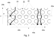
- This flow of granular material is depicted in Figure 3 with arrows 40a and 40b and is opposite to the direction of rotation (-y or y) of the respective roll (10 or 20).
- FIG 3 depicts roll 20 of the roller press of Figure 1 , and as such flow arrows 40a denote an autogenous material flow in rotational direction opposite to the rotational direction y of the roll 20 around its longitudinal axis 20a across the outer cylindrical pressing surface 22 of the roll 20, whereas flow arrows 40b denote an autogenous material flow in a (more or less skewed) longitudinal direction x across the outer cylindrical pressing surface 11-22 of the roll 10-20 in the direction x (or its opposite direction -x) of the side faces 10b-20b of the roll 10-20.
- the autogenous material flows 40a-40b exhibit a low velocity relative to the roll surface 11-22 and can cause excessive wear to the base material of the outer cylindrical pressing surface 11-22 of the roll 10-20, instead of protecting it.
- This autogenous layer flow 40a-40b thus limits the life span of the roll 10-20 and the roller press 1 significantly, but also disrupts the comminution of the granular material by interparticle crushing in the nip 30 between the opposing rolls 10-20.
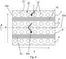
- FIG. 4 depicts an example of a roll 10-20 according to the invention.
- roll 20 is depicted as can be observed from its rotational direction y (see also Figure 1 ).
- the cylindrical body of the roll 10-20 is provided with means 50 for restricting the flow of granular material in the spaces 13-23 between the outwardly extending wear-resistant surface studs 12-22 along the outer cylindrical pressing surface 11-21.
- the flow restricting means 50 are fitted at positions on the pressing surface 11-21, where the possibility of flow 40a of granular material in a rotational direction opposite the rotational direction y of the roll 10-20 along the outer cylindrical pressing surface 11-21 exists, whereas in another example the flow restricting means 50 are fitted at positions on the pressing surface 11-21, where the possibility of flow 40b of granular material in a longitudinal direction x (or -x) along the outer cylindrical pressing surface 11-21 exists.
- Embodiments of these example are shown in Figures 4-5-6 .
- the plurality of outwardly extending wear-resistant surface studs 12-22 are positioned in a pattern consisting of parallel extending pattern lines i1-i2-i3-i4-i5-etc.-etc. on the pressing surface 11-21 and the flow restricting means 50 are provided between adjacent pattern lines, here between pattern lines i1 and i2 and between pattern lines i4 and i5. See also Figure 7 .
- the flow restriction means are made of one or more strip-like elements 50 provided on the outer cylindrical pressing surface 11-21 of the cylindrical body of the roll 10-20.
- the strip-like flow restriction means 50 are composed of assembly-strip consisting of a first strip-like element 50a1-50a2-etc.-etc. positioned in a longitudinal direction x on the outer cylindrical pressing surface 11-21 of the cylindrical body (of the roll 10-20) and at least a further strip-like element 50b1-50b2-50b3-etc.-etc. positioned at an inclined orientation relative to the first strip-like element 50a1-50a2-etc.-etc. Both the first strip-like element 50a1-50a2-etc.-etc.
- strip-like flow restriction means 50 are composed of a series of strip-like elements 50d1-50d2 positioned in a zig-zag orientation between the outwardly extending wear-resistant surface studs 12-22 on the outer cylindrical pressing surface 11-21 of the cylindrical body.
- This example of the flow restriction means 50d1 is in particular useful for application on the outer cylindrical pressing surface 11-21 of the roll 10-20 having a more dense or an irregular pattern of outwardly extending wear-resistant surface studs 12-22.
- the pattern of outwardly extending wear-resistant surface studs 12-22 is composed of closely positioned pattern lines i1-i2-i3-i4-i5-i6-etc.-etc., with the zig-zag orientated strip-like elements 50d1-50d2 being positioned between pattern lines i1-i2 and i5-i6.
- the flow restricting means can be made from a hard metal mixture, e.g. Tungsten Carbide based mixtures.
Landscapes
- Engineering & Computer Science (AREA)
- Food Science & Technology (AREA)
- Crushing And Grinding (AREA)
Description
- The invention relates to a roll for a roller press suitable for comminution of granular material by interparticle crushing according to the preamble of
claim 1, as well as a roller press provided with such a roll as defined inclaim 10. - Such a roll as well as such a roller press is for example disclosed in
US Patent Publication No. 5,269,477 and is implemented for comminution of granular material by interparticle crushing. Granular material is fed into the nip between two opposing rotatable rollers, which are rotating in opposite directions. Under friction the material is compressed between the roller surfaces with the application of an extremely high pressure. - A roll as defined in the preamble of
claim 1 is for example disclosed inEP1502650A1 .WO2014/173377A2 andEP08308970A1 - In this operation, the outer cylindrical pressing surfaces of each roll are exposed to extraordinarily high stressing and high wear. An improvement which has been done is to armor the roller surfaces with a wear-resistant cladding to provide a hardened outer surface.
- Furthermore, in order to improve the draw-in capability of the pressing rollers that must draw the granular material product into the nip by friction and compress it, it is known to provide the outer cylindrical pressing surface of the roll with a plurality of outwardly extending wear-resistant surface studs. The granular material being drawn-in and captured between the studs forms an autogenous layer, which provides a protecting layer for the outer cylindrical pressing surface of the roll.
- However, in certain applications and under specific operational conditions the autogenous layer starts to displace or flow between the outwardly extending wear-resistant surface studs. This flow of granular material has a low velocity relative to the roll and can cause excessive wear to the base material of the outer cylindrical pressing surface of the roll, instead of protecting it. This autogenous layer flow limits the life span of the roll and the roller press significantly, but also disrupts the comminution of the granular material by interparticle crushing in the nip between the opposing rolls.
- It is an object of the present invention to provide a roll design as well as a roller press, which do not suffer from the above identified drawback.
- In a roll according to the invention the cylindrical body of the roll is provided with means for restricting the flow of granular material between the outwardly extending wear-resistant surface studs along the outer cylindrical pressing surface, in accordance with the characterizing part of
claim 1. - Herewith excessive wear to the base material of the outer cylindrical pressing surface of the roll is significantly reduced or even prevented, as well as the comminution of the granular material by interparticle crushing in the nip between the opposing rolls is no longer disrupted.
- The flow restricting means are fitted at positions on the pressing surface, where the possibility of flow of granular material in a rotational direction along the outer cylindrical pressing surface exists, whereas in another example the flow restricting means are fitted at positions on the pressing surface, where the possibility of flow of granular material in a longitudinal direction along the outer cylindrical pressing surface exists.
- In both cases the autogenous layer of granular material present between the outwardly extending wear-resistant surface studs is prevented to fluidize because of the presence of the flow restricting means, thus preventing excessive wear to the base material of the outer cylindrical pressing surface of the roll.
- In yet a further advantageous example the flow restricting means extends in a longitudinal direction along the outer cylindrical pressing surface. Herewith any erosive flow of autogenous layer of granular material in a rotational direction along the circumference of the outer cylindrical pressing surface is prevented.
- In another advantageous example of the roll according to the invention the flow restricting means extends in a rotational direction along the outer cylindrical pressing surface. Herewith any flow of autogenous layer of granular material in a longitudinal direction along the circumference of the outer cylindrical pressing surface in the direction of the end faces thereof is prevented.
- In particular the strip-like flow restriction means are composed of a first strip-like element positioned in a longitudinal direction on the outer cylindrical pressing surface of the cylindrical body (of the roll) and at least a further strip-like element positioned at an inclined orientation relative to the first strip-like element. With this example any damaging, erosive flow of the autogenous layer of granular layer in a rotational as well as in a longitudinal direction along the circumference of the outer cylindrical pressing surface is prevented.
- In yet another advantageous example, the strip-like flow restriction means are composed of a series of strip-like elements positioned in a zig-zag orientation on the outer cylindrical pressing surface of the cylindrical body. This example of the flow restriction means is in particular useful for application on the outer cylindrical pressing surface of the roll having a more dense or an irregular pattern of outwardly extending wear-resistant surface studs.
- Furthermore preferably, the wear-resistant surface studs are made from a material being harder than the material of the outer cylindrical pressing surface.
- Also the flow restricting means can be made from a hard metal mixture, e.g. Tungsten Carbide based mixtures.
- The invention will now be described in more details in reference to accompanying drawings, which drawings show in:
-
Figure 1 a schematic embodiment of a roller press consisting of a set of two opposing rolls according to the state of the art; -
Figure 2 a schematic cross sectional detail of the roll ofFigure 1 ; -
Figure 3 a schematic detail of the flow of the autogenous layer of granular material across the cylindrical surface of the roll ofFigure 1 ; -
Figure 4 a first embodiment of a roll provided with flow restriction means according to the invention; -
Figure 5 a second embodiment of a roll provided with flow restriction means according to the invention; -
Figure 6 a third embodiment of a roll provided with flow restriction means according to the invention; -
Figure 7 a schematic cross sectional detail of the roll ofFigure 4 ; - For a better understanding of the invention like parts in the drawings are be denoted with like reference numerals.
-
Figure 1 depicts in a schematic manner aroller press 1 suitable for comminution of granular material by interparticle crushing according to the state of the art. Such aroller press 1 is to be used for comminution or grinding of granular material by interparticle crushing and is composed of a set of two opposing rolls orrollers - Each roll 10-20 can be rotated around their longitudinal axis of
rotation 10a-20a using suitable (non-depicted) roll driving means. For a proper operation of theroller press 1, both rolls 10-20 of the set of rolls are rotated in opposite rotational directions, as shown by the rotational arrows y and -y on the left ofFigure 1 . - Both rolls 10-20 are orientated parallel from each other in their longitudinal orientation and at some distance from each other, as shown in
Figure 1 . The distanced orientation as shown inFigure 1 creates a space between the two opposing outer cylindrical pressing surfaces 11-21 of both cylindrical bodies, which space is denoted withreference numeral 30 and also indicated as an interparticle crushing pressing nip. - During operation of the roller press granular material, which for example is being processed in the mining or cement/mortar industry, is fed into the
nip 30 between the two opposing rotatable rollers 10-20, which are rotating in opposite directions y and -y. Under friction the granular material is compressed between the roller surfaces 11-21 with the application of extremely high pressures, thereby reducing the solid materials to a smaller average particle size. - During this type of mineral processing, the outer cylindrical pressing surfaces 11-21 of each roll 10-20 are exposed to extraordinarily high stressing and high wear. An improvement which has been done is to armor the roller surfaces 11-21 with a wear-resistant cladding (not shown) to provide a hardened outer surface.
- In addition, in order to improve the draw-in capability of the pressing rollers 10-20 that must draw the granular material product into the
nip 30 by friction and compress it, it is known to provide the outer cylindrical pressing surface 11-21 of each counter-rotating roll 10-20 with a plurality of outwardly extending wear-resistant surface studs 12-22. Usually the outwardly extending wear-resistant surface studs 12-22 are made from a material being harder than the material of the outer cylindrical pressing surface 11-21 and the studs 12-22 extends at a height h of approx. 5-10 mm from the surface 11-21. - The granular material being drawn-in and captured in the spaces 13-23 between the studs 12-22 forms an
autogenous layer 40, which provides a protecting layer for the outer cylindrical pressing surface 11-22 of the roll 10-20. SeeFigure 2 . Herewith the lifespan of the roll 10-20 is extended and the comminution of granular material by interparticle crushing is improved. - However, in certain applications and under specific operational conditions the
autogenous layer 40 starts to displace or flow in the spaces 13-23 between the outwardly extending wear-resistant surface studs 12-22. This flow of granular material is depicted inFigure 3 witharrows - In this example
Figure 3 depictsroll 20 of the roller press ofFigure 1 , and assuch flow arrows 40a denote an autogenous material flow in rotational direction opposite to the rotational direction y of theroll 20 around itslongitudinal axis 20a across the outer cylindricalpressing surface 22 of theroll 20, whereasflow arrows 40b denote an autogenous material flow in a (more or less skewed) longitudinal direction x across the outer cylindrical pressing surface 11-22 of the roll 10-20 in the direction x (or its opposite direction -x) of the side faces 10b-20b of the roll 10-20. - The autogenous material flows 40a-40b exhibit a low velocity relative to the roll surface 11-22 and can cause excessive wear to the base material of the outer cylindrical pressing surface 11-22 of the roll 10-20, instead of protecting it. This autogenous layer flow 40a-40b thus limits the life span of the roll 10-20 and the
roller press 1 significantly, but also disrupts the comminution of the granular material by interparticle crushing in thenip 30 between the opposing rolls 10-20. - As a solution for the above described phenomenon of autogenous layer flow
Figure 4 depicts an example of a roll 10-20 according to the invention. In thisFigure roll 20 is depicted as can be observed from its rotational direction y (see alsoFigure 1 ). The cylindrical body of the roll 10-20 is provided withmeans 50 for restricting the flow of granular material in the spaces 13-23 between the outwardly extending wear-resistant surface studs 12-22 along the outer cylindrical pressing surface 11-21. - In particular the flow restricting means 50 are fitted at positions on the pressing surface 11-21, where the possibility of
flow 40a of granular material in a rotational direction opposite the rotational direction y of the roll 10-20 along the outer cylindrical pressing surface 11-21 exists, whereas in another example the flow restricting means 50 are fitted at positions on the pressing surface 11-21, where the possibility offlow 40b of granular material in a longitudinal direction x (or -x) along the outer cylindrical pressing surface 11-21 exists. - Embodiments of these example are shown in
Figures 4-5-6 . InFigure 4 the plurality of outwardly extending wear-resistant surface studs 12-22 are positioned in a pattern consisting of parallel extending pattern lines i1-i2-i3-i4-i5-etc.-etc. on the pressing surface 11-21 and theflow restricting means 50 are provided between adjacent pattern lines, here between pattern lines i1 and i2 and between pattern lines i4 and i5. See alsoFigure 7 . - In this the design the flow restriction means are made of one or more strip-
like elements 50 provided on the outer cylindrical pressing surface 11-21 of the cylindrical body of the roll 10-20. In particular the strip-like flow restriction means 50 are composed of assembly-strip consisting of a first strip-like element 50a1-50a2-etc.-etc. positioned in a longitudinal direction x on the outer cylindrical pressing surface 11-21 of the cylindrical body (of the roll 10-20) and at least a further strip-like element 50b1-50b2-50b3-etc.-etc. positioned at an inclined orientation relative to the first strip-like element 50a1-50a2-etc.-etc. Both the first strip-like element 50a1-50a2-etc.-etc. and the at least further strip-like element 50b1-50b2-50b3-etc.-etc. are interconnected or converge at their connections 50c1-50c2-etc.-etc. With this example any damaging, erosive flow of theautogenous layer 40 of granular layer in a rotational direction y (flowarrow 40a) as well as in a (more or less) longitudinal direction x (flowarrow 40b) towards the side faces 10b-20b of the roll 10-20 along the circumference (seen in rotational or longitudinal direction) of the outer cylindrical pressing surface 11-21 is prevented. - Another advantageous example is shown in
Figure 6 , wherein the strip-like flow restriction means 50 are composed of a series of strip-like elements 50d1-50d2 positioned in a zig-zag orientation between the outwardly extending wear-resistant surface studs 12-22 on the outer cylindrical pressing surface 11-21 of the cylindrical body. This example of the flow restriction means 50d1 is in particular useful for application on the outer cylindrical pressing surface 11-21 of the roll 10-20 having a more dense or an irregular pattern of outwardly extending wear-resistant surface studs 12-22. Also in this example the pattern of outwardly extending wear-resistant surface studs 12-22 is composed of closely positioned pattern lines i1-i2-i3-i4-i5-i6-etc.-etc., with the zig-zag orientated strip-like elements 50d1-50d2 being positioned between pattern lines i1-i2 and i5-i6. - With the examples above excessive wear to the base material of the outer cylindrical pressing surface 11-21 of the roll 10-20 is significantly reduced or even prevented, as well as the comminution of the granular material by interparticle crushing in the
nip 30 between the opposing rolls 10-20 is no longer disrupted. Furthermore theautogenous layer 40 of granular material present in the spaces 13-23 between the outwardly extending wear-resistant surface studs 12-22 is prevented to fluidize because of the presence of the flow restricting means 50 (50a1-50a2-etc.; 50b1-50b2-etc.; 50d1-50d2-etc.), thus preventingerosive flow 40a-40b and excessive wear to the base material of the outer cylindrical pressing surface of the roll 10-20. - Preferably, the flow restricting means can be made from a hard metal mixture, e.g. Tungsten Carbide based mixtures.
-
- 1
- Roller press
- 10/20
- First/second roll of set of rollers
- 10a/20a
- Axis of rotation
- 10b/20b
- Side face of cylindrical body of roll
- 11/21
- Outer cylindrical pressing surface of cylindrical body
- 12/22
- Outwardly extending wear-resistant surface stud
- 13/23
- Space between adjacent outwardly extending wear-resistant surface studs
- 30
- Nip between first and second roll
- 40
- Autogenous layer of granular material
- 40a
- Flow of granular material between the surface studs in circumferential direction
- 40b
- Flow of granular material between the surface studs in longitudinal direction (in the direction of the side faces)
- 50
- Means for restricting the flow of granular material (first embodiment)
- 50a1-2
- Fist strip element of flow restriction means (second embodiment)
- 50b1-2-3
- Second strip element of flow restriction means (second embodiment)
- 50c1-c2
- Interconnection between first and second strip-elements
- i1-i2-etc.
- pattern lines of studs on the pressing surface
Claims (10)
- A roll (10; 20) for a roller press (1) suitable for comminution of granular material (40) by interparticle crushing, said roll (10; 20) comprising:a cylindrical body having an outer cylindrical pressing surface (11; 21) for use with an opposing roll in an interparticle crushing pressing nip (30);a plurality of outwardly extending wear-resistant surface studs (12; 22) positioned on the pressing surface (11; 21); whereinthe cylindrical body is provided with means (50) for restricting the flow of granular material (40) between the outwardly extending wear-resistant surface studs (12; 22) along the outer cylindrical pressing surface (11; 21), whereinthe plurality of outwardly extending wear-resistant surface studs (12; 22) are positioned in a pattern consisting of parallel extending lines (i1-i2-i3-i4-i5-...) on the pressing surface (11; 21), characterized in thatthe flow restricting means (50) are provided between adjacent pattern lines (i1-i2-i3-i4-i5-...), and whereinthe flow restriction means (50) are made of one or more strip-like elements (50a1-50b1-50c1; 50a2-50b2-50c2; 50b3; 50d1-50d2) provided on the outer cylindrical pressing surface (11; 21) of the cylindrical body.
- The roll (10; 20) according to claim 1, wherein the flow restricting means (50) are fitted at positions on the pressing surface (11; 21), where the possibility of flow (40a) of granular material in a rotational direction along the outer cylindrical pressing surface (11; 21) exists.
- The roll (10; 20) according to claim 1 or 2, wherein the flow restricting means (50) are fitted at positions on the pressing surface, where the possibility of flow (40b) of granular material in a longitudinal direction along the outer cylindrical pressing surface (11; 21) exists.
- The roll (10; 20) according to any one or more of the preceding claims, wherein the flow restricting means (50) extends in a longitudinal direction along the outer cylindrical pressing surface (11; 21).
- The roll (10; 20) according to any one or more of the preceding claims, wherein the flow restricting means (50) extends in a rotational direction along the outer cylindrical pressing surface (11; 21).
- The roll (10; 20) according to claim 1, wherein the strip-like flow restriction means (50) are composed of a first strip-like element (50a1-50a2) positioned in a longitudinal direction on the outer cylindrical pressing surface (11; 21) of the cylindrical body and at least a further strip-like element (50b1-50b2; 50b3) positioned at an inclined orientation relative to the first strip-like element (50a1-50a2).
- The roll (10; 20) according to claim 1, wherein the strip-like flow restriction means (50) are composed of a series of strip-like elements (50d1-50d2) positioned in a zig-zag orientation on the outer cylindrical pressing surface (11; 21) of the cylindrical body.
- The roll (10; 20) according to any one or more of the preceding claims, wherein the wear-resistant surface studs (12; 22) are made from a material being harder than the material of the outer cylindrical pressing surface (11; 21).
- The roll (10; 20) according to any one or more of the preceding claims, wherein the flow restricting means (50; 50a1-50b1-50c1; 50a2-50b2-50c2; 50b3; 50d1-50d2) are made from a hard metal mixture, e.g. Tungsten Carbide based mixtures.
- A roller press (1) suitable for comminution of granular material by interparticle crushing, said roller press (1) comprising:at least one set of two opposing rolls (10; 20), each roll consisting of a cylindrical body having an outer cylindrical pressing surface (11; 21) for use with the opposing roll in an interparticle crushing pressing nip (30); whereinat least one roll is provided with means (50; 50a1-50b1-50c1; 50a2-50b2-50c2; 50b3; 50d1-50d2) for restricting the flow of granular material (40) between the outwardly extending wear-resistant surface studs (12; 22) along the outer cylindrical pressing surface (11; 21) according to any one or more of the preceding claims.
Applications Claiming Priority (2)
| Application Number | Priority Date | Filing Date | Title |
|---|---|---|---|
| NL2020403A NL2020403B1 (en) | 2018-02-08 | 2018-02-08 | A roll for a roller press suitable for comminution of granular material by interparticle crushing, as well as a roller press provided with such a roll. |
| PCT/NL2019/050077 WO2019156558A1 (en) | 2018-02-08 | 2019-02-07 | A roll for a roller press, as well as a roller press provided with such a roll |
Publications (3)
| Publication Number | Publication Date |
|---|---|
| EP3749458A1 EP3749458A1 (en) | 2020-12-16 |
| EP3749458C0 EP3749458C0 (en) | 2023-11-15 |
| EP3749458B1 true EP3749458B1 (en) | 2023-11-15 |
Family
ID=62002360
Family Applications (1)
| Application Number | Title | Priority Date | Filing Date |
|---|---|---|---|
| EP19714871.1A Active EP3749458B1 (en) | 2018-02-08 | 2019-02-07 | A roll for a roller press, as well as a roller press provided with such a roll |
Country Status (11)
| Country | Link |
|---|---|
| US (1) | US11577254B2 (en) |
| EP (1) | EP3749458B1 (en) |
| CN (1) | CN112218721B (en) |
| AR (1) | AR114098A1 (en) |
| AU (1) | AU2019217200B2 (en) |
| CA (1) | CA3090463C (en) |
| CL (1) | CL2020002030A1 (en) |
| NL (1) | NL2020403B1 (en) |
| PE (1) | PE20201329A1 (en) |
| WO (1) | WO2019156558A1 (en) |
| ZA (1) | ZA202004604B (en) |
Families Citing this family (1)
| Publication number | Priority date | Publication date | Assignee | Title |
|---|---|---|---|---|
| NL2020403B1 (en) | 2018-02-08 | 2019-08-19 | Weir Minerals Netherlands Bv | A roll for a roller press suitable for comminution of granular material by interparticle crushing, as well as a roller press provided with such a roll. |
Family Cites Families (13)
| Publication number | Priority date | Publication date | Assignee | Title |
|---|---|---|---|---|
| DE4132474A1 (en) | 1991-05-28 | 1992-12-03 | Kloeckner Humboldt Deutz Ag | WEAR-RESISTANT GRINDING ROLLER FOR USE IN ROLLING MACHINES, ESPECIALLY IN HIGH PRESSURE ROLLING PRESSES |
| US5927627A (en) * | 1996-06-05 | 1999-07-27 | Honey Creek Industries, Inc. | Continuous crumbing machine for recycling rubber tires |
| DE19638237A1 (en) * | 1996-09-19 | 1998-03-26 | Deutz Ag | Wear-resistant surface armor for the rollers of high-pressure roller presses for pressure reduction of granular goods |
| DE19646030A1 (en) * | 1996-11-08 | 1998-05-14 | Deutz Ag | Wear-resistant surface armor for the rollers of high-pressure roller presses for pressure reduction of granular goods |
| US7556668B2 (en) * | 2001-12-05 | 2009-07-07 | Baker Hughes Incorporated | Consolidated hard materials, methods of manufacture, and applications |
| DE10335115A1 (en) * | 2003-07-31 | 2005-02-24 | Polysius Ag | grinding roll |
| US8308096B2 (en) * | 2009-07-14 | 2012-11-13 | TDY Industries, LLC | Reinforced roll and method of making same |
| DE102009039928B3 (en) * | 2009-08-17 | 2011-03-03 | Khd Humboldt Wedag Gmbh | Roll press screen armoring with ring-shaped bolts and method for renewing the reinforcement of this grid armor |
| CN104039454B (en) * | 2011-10-07 | 2015-10-14 | Fl史密斯公司 | Edge wear parts for roller presses |
| US8833687B2 (en) * | 2012-04-20 | 2014-09-16 | Metso Minerals Industries, Inc. | Crushing roll with edge protection |
| CN102896013B (en) * | 2012-09-26 | 2015-05-27 | 成都利君实业股份有限公司 | Roller mill and self-synchronizing wearing roller of high-pressure roller mill |
| DE102013104098A1 (en) * | 2013-04-23 | 2014-10-23 | Thyssenkrupp Industrial Solutions Ag | Device for the comminution of abrasive materials |
| NL2020403B1 (en) | 2018-02-08 | 2019-08-19 | Weir Minerals Netherlands Bv | A roll for a roller press suitable for comminution of granular material by interparticle crushing, as well as a roller press provided with such a roll. |
-
2018
- 2018-02-08 NL NL2020403A patent/NL2020403B1/en active
-
2019
- 2019-02-07 WO PCT/NL2019/050077 patent/WO2019156558A1/en not_active Ceased
- 2019-02-07 CN CN201980012006.1A patent/CN112218721B/en active Active
- 2019-02-07 PE PE2020001130A patent/PE20201329A1/en unknown
- 2019-02-07 CA CA3090463A patent/CA3090463C/en active Active
- 2019-02-07 AU AU2019217200A patent/AU2019217200B2/en active Active
- 2019-02-07 EP EP19714871.1A patent/EP3749458B1/en active Active
- 2019-02-07 US US16/968,043 patent/US11577254B2/en active Active
- 2019-02-08 AR ARP190100307A patent/AR114098A1/en active IP Right Grant
-
2020
- 2020-07-24 ZA ZA2020/04604A patent/ZA202004604B/en unknown
- 2020-08-04 CL CL2020002030A patent/CL2020002030A1/en unknown
Also Published As
| Publication number | Publication date |
|---|---|
| US11577254B2 (en) | 2023-02-14 |
| AR114098A1 (en) | 2020-07-22 |
| CN112218721B (en) | 2022-04-29 |
| ZA202004604B (en) | 2023-12-20 |
| RU2020128243A3 (en) | 2022-04-18 |
| RU2020128243A (en) | 2022-03-09 |
| BR112020015347A2 (en) | 2020-12-08 |
| EP3749458C0 (en) | 2023-11-15 |
| EP3749458A1 (en) | 2020-12-16 |
| CA3090463C (en) | 2024-01-02 |
| AU2019217200A1 (en) | 2020-08-13 |
| CN112218721A (en) | 2021-01-12 |
| WO2019156558A1 (en) | 2019-08-15 |
| WO2019156558A8 (en) | 2019-11-21 |
| CL2020002030A1 (en) | 2020-10-16 |
| CA3090463A1 (en) | 2019-08-15 |
| US20210031206A1 (en) | 2021-02-04 |
| PE20201329A1 (en) | 2020-11-25 |
| AU2019217200B2 (en) | 2023-04-13 |
| NL2020403B1 (en) | 2019-08-19 |
Similar Documents
| Publication | Publication Date | Title |
|---|---|---|
| EP3248685A2 (en) | Roller crusher having at least one roller comprising a flange | |
| US8708264B2 (en) | Roller crusher having at least one roller comprising a flange | |
| AU2015238874B2 (en) | Roller crusher having at least one roller comprising a flange | |
| CA3090463C (en) | A roll for a roller press, as well as a roller press provided with such a roll | |
| CN102896013B (en) | Roller mill and self-synchronizing wearing roller of high-pressure roller mill | |
| EP4359135B1 (en) | Grinding roll | |
| RU2773745C2 (en) | Roll for roller press, as well as roller press equipped with such a roll | |
| US6588689B2 (en) | Apparatus for crushing material | |
| US5381977A (en) | Apparatus for material bed comminution of brittle material for grinding | |
| BR112020015347B1 (en) | ROLLER FOR ROLLER PRESS AS WELL AS ROLLER PRESS PROVIDED WITH SUCH ROLLER | |
| EP4201527A1 (en) | Liner plate in connection to a material processing handling system | |
| AU762265B2 (en) | Apparatus for crushing material | |
| CN118785977A (en) | Lifting linings for rotary tube mills | |
| AU2020230232A1 (en) | A Grinding Assembly and a Roller Assembly | |
| CZ3097A3 (en) | Single-roll crusher |
Legal Events
| Date | Code | Title | Description |
|---|---|---|---|
| STAA | Information on the status of an ep patent application or granted ep patent |
Free format text: STATUS: UNKNOWN |
|
| STAA | Information on the status of an ep patent application or granted ep patent |
Free format text: STATUS: THE INTERNATIONAL PUBLICATION HAS BEEN MADE |
|
| PUAI | Public reference made under article 153(3) epc to a published international application that has entered the european phase |
Free format text: ORIGINAL CODE: 0009012 |
|
| STAA | Information on the status of an ep patent application or granted ep patent |
Free format text: STATUS: REQUEST FOR EXAMINATION WAS MADE |
|
| 17P | Request for examination filed |
Effective date: 20200819 |
|
| AK | Designated contracting states |
Kind code of ref document: A1 Designated state(s): AL AT BE BG CH CY CZ DE DK EE ES FI FR GB GR HR HU IE IS IT LI LT LU LV MC MK MT NL NO PL PT RO RS SE SI SK SM TR |
|
| AX | Request for extension of the european patent |
Extension state: BA ME |
|
| DAV | Request for validation of the european patent (deleted) | ||
| DAX | Request for extension of the european patent (deleted) | ||
| GRAP | Despatch of communication of intention to grant a patent |
Free format text: ORIGINAL CODE: EPIDOSNIGR1 |
|
| STAA | Information on the status of an ep patent application or granted ep patent |
Free format text: STATUS: GRANT OF PATENT IS INTENDED |
|
| GRAS | Grant fee paid |
Free format text: ORIGINAL CODE: EPIDOSNIGR3 |
|
| GRAA | (expected) grant |
Free format text: ORIGINAL CODE: 0009210 |
|
| STAA | Information on the status of an ep patent application or granted ep patent |
Free format text: STATUS: THE PATENT HAS BEEN GRANTED |
|
| INTG | Intention to grant announced |
Effective date: 20230920 |
|
| AK | Designated contracting states |
Kind code of ref document: B1 Designated state(s): AL AT BE BG CH CY CZ DE DK EE ES FI FR GB GR HR HU IE IS IT LI LT LU LV MC MK MT NL NO PL PT RO RS SE SI SK SM TR |
|
| REG | Reference to a national code |
Ref country code: CH Ref legal event code: EP Ref country code: GB Ref legal event code: FG4D |
|
| REG | Reference to a national code |
Ref country code: DE Ref legal event code: R096 Ref document number: 602019041439 Country of ref document: DE |
|
| REG | Reference to a national code |
Ref country code: IE Ref legal event code: FG4D |
|
| U01 | Request for unitary effect filed |
Effective date: 20231115 |
|
| U07 | Unitary effect registered |
Designated state(s): AT BE BG DE DK EE FI FR IT LT LU LV MT NL PT SE SI Effective date: 20231122 |
|
| U20 | Renewal fee for the european patent with unitary effect paid |
Year of fee payment: 6 Effective date: 20240227 |
|
| PG25 | Lapsed in a contracting state [announced via postgrant information from national office to epo] |
Ref country code: GR Free format text: LAPSE BECAUSE OF FAILURE TO SUBMIT A TRANSLATION OF THE DESCRIPTION OR TO PAY THE FEE WITHIN THE PRESCRIBED TIME-LIMIT Effective date: 20240216 |
|
| PG25 | Lapsed in a contracting state [announced via postgrant information from national office to epo] |
Ref country code: IS Free format text: LAPSE BECAUSE OF FAILURE TO SUBMIT A TRANSLATION OF THE DESCRIPTION OR TO PAY THE FEE WITHIN THE PRESCRIBED TIME-LIMIT Effective date: 20240315 |
|
| PG25 | Lapsed in a contracting state [announced via postgrant information from national office to epo] |
Ref country code: ES Free format text: LAPSE BECAUSE OF FAILURE TO SUBMIT A TRANSLATION OF THE DESCRIPTION OR TO PAY THE FEE WITHIN THE PRESCRIBED TIME-LIMIT Effective date: 20231115 |
|
| PG25 | Lapsed in a contracting state [announced via postgrant information from national office to epo] |
Ref country code: IS Free format text: LAPSE BECAUSE OF FAILURE TO SUBMIT A TRANSLATION OF THE DESCRIPTION OR TO PAY THE FEE WITHIN THE PRESCRIBED TIME-LIMIT Effective date: 20240315 Ref country code: GR Free format text: LAPSE BECAUSE OF FAILURE TO SUBMIT A TRANSLATION OF THE DESCRIPTION OR TO PAY THE FEE WITHIN THE PRESCRIBED TIME-LIMIT Effective date: 20240216 Ref country code: ES Free format text: LAPSE BECAUSE OF FAILURE TO SUBMIT A TRANSLATION OF THE DESCRIPTION OR TO PAY THE FEE WITHIN THE PRESCRIBED TIME-LIMIT Effective date: 20231115 |
|
| PG25 | Lapsed in a contracting state [announced via postgrant information from national office to epo] |
Ref country code: RS Free format text: LAPSE BECAUSE OF FAILURE TO SUBMIT A TRANSLATION OF THE DESCRIPTION OR TO PAY THE FEE WITHIN THE PRESCRIBED TIME-LIMIT Effective date: 20231115 Ref country code: PL Free format text: LAPSE BECAUSE OF FAILURE TO SUBMIT A TRANSLATION OF THE DESCRIPTION OR TO PAY THE FEE WITHIN THE PRESCRIBED TIME-LIMIT Effective date: 20231115 Ref country code: NO Free format text: LAPSE BECAUSE OF FAILURE TO SUBMIT A TRANSLATION OF THE DESCRIPTION OR TO PAY THE FEE WITHIN THE PRESCRIBED TIME-LIMIT Effective date: 20240215 Ref country code: HR Free format text: LAPSE BECAUSE OF FAILURE TO SUBMIT A TRANSLATION OF THE DESCRIPTION OR TO PAY THE FEE WITHIN THE PRESCRIBED TIME-LIMIT Effective date: 20231115 |
|
| PG25 | Lapsed in a contracting state [announced via postgrant information from national office to epo] |
Ref country code: CZ Free format text: LAPSE BECAUSE OF FAILURE TO SUBMIT A TRANSLATION OF THE DESCRIPTION OR TO PAY THE FEE WITHIN THE PRESCRIBED TIME-LIMIT Effective date: 20231115 |
|
| PG25 | Lapsed in a contracting state [announced via postgrant information from national office to epo] |
Ref country code: SK Free format text: LAPSE BECAUSE OF FAILURE TO SUBMIT A TRANSLATION OF THE DESCRIPTION OR TO PAY THE FEE WITHIN THE PRESCRIBED TIME-LIMIT Effective date: 20231115 |
|
| PG25 | Lapsed in a contracting state [announced via postgrant information from national office to epo] |
Ref country code: SM Free format text: LAPSE BECAUSE OF FAILURE TO SUBMIT A TRANSLATION OF THE DESCRIPTION OR TO PAY THE FEE WITHIN THE PRESCRIBED TIME-LIMIT Effective date: 20231115 Ref country code: SK Free format text: LAPSE BECAUSE OF FAILURE TO SUBMIT A TRANSLATION OF THE DESCRIPTION OR TO PAY THE FEE WITHIN THE PRESCRIBED TIME-LIMIT Effective date: 20231115 Ref country code: RO Free format text: LAPSE BECAUSE OF FAILURE TO SUBMIT A TRANSLATION OF THE DESCRIPTION OR TO PAY THE FEE WITHIN THE PRESCRIBED TIME-LIMIT Effective date: 20231115 Ref country code: CZ Free format text: LAPSE BECAUSE OF FAILURE TO SUBMIT A TRANSLATION OF THE DESCRIPTION OR TO PAY THE FEE WITHIN THE PRESCRIBED TIME-LIMIT Effective date: 20231115 |
|
| REG | Reference to a national code |
Ref country code: DE Ref legal event code: R097 Ref document number: 602019041439 Country of ref document: DE |
|
| PLBE | No opposition filed within time limit |
Free format text: ORIGINAL CODE: 0009261 |
|
| STAA | Information on the status of an ep patent application or granted ep patent |
Free format text: STATUS: NO OPPOSITION FILED WITHIN TIME LIMIT |
|
| PG25 | Lapsed in a contracting state [announced via postgrant information from national office to epo] |
Ref country code: MC Free format text: LAPSE BECAUSE OF FAILURE TO SUBMIT A TRANSLATION OF THE DESCRIPTION OR TO PAY THE FEE WITHIN THE PRESCRIBED TIME-LIMIT Effective date: 20231115 |
|
| REG | Reference to a national code |
Ref country code: CH Ref legal event code: PL |
|
| PG25 | Lapsed in a contracting state [announced via postgrant information from national office to epo] |
Ref country code: CH Free format text: LAPSE BECAUSE OF NON-PAYMENT OF DUE FEES Effective date: 20240229 |
|
| 26N | No opposition filed |
Effective date: 20240819 |
|
| GBPC | Gb: european patent ceased through non-payment of renewal fee |
Effective date: 20240215 |
|
| PG25 | Lapsed in a contracting state [announced via postgrant information from national office to epo] |
Ref country code: CH Free format text: LAPSE BECAUSE OF NON-PAYMENT OF DUE FEES Effective date: 20240229 |
|
| PG25 | Lapsed in a contracting state [announced via postgrant information from national office to epo] |
Ref country code: GB Free format text: LAPSE BECAUSE OF NON-PAYMENT OF DUE FEES Effective date: 20240215 |
|
| PG25 | Lapsed in a contracting state [announced via postgrant information from national office to epo] |
Ref country code: IE Free format text: LAPSE BECAUSE OF NON-PAYMENT OF DUE FEES Effective date: 20240207 |
|
| PG25 | Lapsed in a contracting state [announced via postgrant information from national office to epo] |
Ref country code: IE Free format text: LAPSE BECAUSE OF NON-PAYMENT OF DUE FEES Effective date: 20240207 Ref country code: GB Free format text: LAPSE BECAUSE OF NON-PAYMENT OF DUE FEES Effective date: 20240215 |
|
| U20 | Renewal fee for the european patent with unitary effect paid |
Year of fee payment: 7 Effective date: 20250227 |
|
| PG25 | Lapsed in a contracting state [announced via postgrant information from national office to epo] |
Ref country code: CY Free format text: LAPSE BECAUSE OF FAILURE TO SUBMIT A TRANSLATION OF THE DESCRIPTION OR TO PAY THE FEE WITHIN THE PRESCRIBED TIME-LIMIT; INVALID AB INITIO Effective date: 20190207 |
|
| PG25 | Lapsed in a contracting state [announced via postgrant information from national office to epo] |
Ref country code: HU Free format text: LAPSE BECAUSE OF FAILURE TO SUBMIT A TRANSLATION OF THE DESCRIPTION OR TO PAY THE FEE WITHIN THE PRESCRIBED TIME-LIMIT; INVALID AB INITIO Effective date: 20190207 |
|
| PG25 | Lapsed in a contracting state [announced via postgrant information from national office to epo] |
Ref country code: TR Free format text: LAPSE BECAUSE OF FAILURE TO SUBMIT A TRANSLATION OF THE DESCRIPTION OR TO PAY THE FEE WITHIN THE PRESCRIBED TIME-LIMIT Effective date: 20231115 |
|
| U20 | Renewal fee for the european patent with unitary effect paid |
Year of fee payment: 8 Effective date: 20260227 |