EP3749262B1 - Vorrichtung zur unterstützung der verwendung einer vorrichtung zur abgabe eines flüssigen produkts - Google Patents
Vorrichtung zur unterstützung der verwendung einer vorrichtung zur abgabe eines flüssigen produkts Download PDFInfo
- Publication number
- EP3749262B1 EP3749262B1 EP19705134.5A EP19705134A EP3749262B1 EP 3749262 B1 EP3749262 B1 EP 3749262B1 EP 19705134 A EP19705134 A EP 19705134A EP 3749262 B1 EP3749262 B1 EP 3749262B1
- Authority
- EP
- European Patent Office
- Prior art keywords
- dispensing
- drop
- liquid product
- volume
- dispensing device
- Prior art date
- Legal status (The legal status is an assumption and is not a legal conclusion. Google has not performed a legal analysis and makes no representation as to the accuracy of the status listed.)
- Active
Links
Images


Classifications
-
- A—HUMAN NECESSITIES
- A61—MEDICAL OR VETERINARY SCIENCE; HYGIENE
- A61F—FILTERS IMPLANTABLE INTO BLOOD VESSELS; PROSTHESES; DEVICES PROVIDING PATENCY TO, OR PREVENTING COLLAPSING OF, TUBULAR STRUCTURES OF THE BODY, e.g. STENTS; ORTHOPAEDIC, NURSING OR CONTRACEPTIVE DEVICES; FOMENTATION; TREATMENT OR PROTECTION OF EYES OR EARS; BANDAGES, DRESSINGS OR ABSORBENT PADS; FIRST-AID KITS
- A61F9/00—Methods or devices for treatment of the eyes; Devices for putting in contact-lenses; Devices to correct squinting; Apparatus to guide the blind; Protective devices for the eyes, carried on the body or in the hand
- A61F9/0008—Introducing ophthalmic products into the ocular cavity or retaining products therein
- A61F9/0026—Ophthalmic product dispenser attachments to facilitate positioning near the eye
-
- A—HUMAN NECESSITIES
- A61—MEDICAL OR VETERINARY SCIENCE; HYGIENE
- A61F—FILTERS IMPLANTABLE INTO BLOOD VESSELS; PROSTHESES; DEVICES PROVIDING PATENCY TO, OR PREVENTING COLLAPSING OF, TUBULAR STRUCTURES OF THE BODY, e.g. STENTS; ORTHOPAEDIC, NURSING OR CONTRACEPTIVE DEVICES; FOMENTATION; TREATMENT OR PROTECTION OF EYES OR EARS; BANDAGES, DRESSINGS OR ABSORBENT PADS; FIRST-AID KITS
- A61F9/00—Methods or devices for treatment of the eyes; Devices for putting in contact-lenses; Devices to correct squinting; Apparatus to guide the blind; Protective devices for the eyes, carried on the body or in the hand
- A61F9/0008—Introducing ophthalmic products into the ocular cavity or retaining products therein
-
- A—HUMAN NECESSITIES
- A61—MEDICAL OR VETERINARY SCIENCE; HYGIENE
- A61M—DEVICES FOR INTRODUCING MEDIA INTO, OR ONTO, THE BODY; DEVICES FOR TRANSDUCING BODY MEDIA OR FOR TAKING MEDIA FROM THE BODY; DEVICES FOR PRODUCING OR ENDING SLEEP OR STUPOR
- A61M31/00—Devices for introducing or retaining media, e.g. remedies, in cavities of the body
-
- A—HUMAN NECESSITIES
- A61—MEDICAL OR VETERINARY SCIENCE; HYGIENE
- A61M—DEVICES FOR INTRODUCING MEDIA INTO, OR ONTO, THE BODY; DEVICES FOR TRANSDUCING BODY MEDIA OR FOR TAKING MEDIA FROM THE BODY; DEVICES FOR PRODUCING OR ENDING SLEEP OR STUPOR
- A61M35/00—Devices for applying media, e.g. remedies, on the human body
- A61M35/003—Portable hand-held applicators having means for dispensing or spreading integral media
-
- G—PHYSICS
- G01—MEASURING; TESTING
- G01C—MEASURING DISTANCES, LEVELS OR BEARINGS; SURVEYING; NAVIGATION; GYROSCOPIC INSTRUMENTS; PHOTOGRAMMETRY OR VIDEOGRAMMETRY
- G01C9/00—Measuring inclination, e.g. by clinometers, by levels
- G01C9/02—Details
-
- G—PHYSICS
- G01—MEASURING; TESTING
- G01F—MEASURING VOLUME, VOLUME FLOW, MASS FLOW OR LIQUID LEVEL; METERING BY VOLUME
- G01F22/00—Methods or apparatus for measuring volume of fluids or fluent solid material, not otherwise provided for
-
- G—PHYSICS
- G01—MEASURING; TESTING
- G01L—MEASURING FORCE, STRESS, TORQUE, WORK, MECHANICAL POWER, MECHANICAL EFFICIENCY, OR FLUID PRESSURE
- G01L1/00—Measuring force or stress, in general
- G01L1/20—Measuring force or stress, in general by measuring variations in ohmic resistance of solid materials or of electrically-conductive fluids; by making use of electrokinetic cells, i.e. liquid-containing cells wherein an electrical potential is produced or varied upon the application of stress
- G01L1/22—Measuring force or stress, in general by measuring variations in ohmic resistance of solid materials or of electrically-conductive fluids; by making use of electrokinetic cells, i.e. liquid-containing cells wherein an electrical potential is produced or varied upon the application of stress using resistance strain gauges
-
- A—HUMAN NECESSITIES
- A61—MEDICAL OR VETERINARY SCIENCE; HYGIENE
- A61M—DEVICES FOR INTRODUCING MEDIA INTO, OR ONTO, THE BODY; DEVICES FOR TRANSDUCING BODY MEDIA OR FOR TAKING MEDIA FROM THE BODY; DEVICES FOR PRODUCING OR ENDING SLEEP OR STUPOR
- A61M2205/00—General characteristics of the apparatus
- A61M2205/33—Controlling, regulating or measuring
- A61M2205/3306—Optical measuring means
-
- A—HUMAN NECESSITIES
- A61—MEDICAL OR VETERINARY SCIENCE; HYGIENE
- A61M—DEVICES FOR INTRODUCING MEDIA INTO, OR ONTO, THE BODY; DEVICES FOR TRANSDUCING BODY MEDIA OR FOR TAKING MEDIA FROM THE BODY; DEVICES FOR PRODUCING OR ENDING SLEEP OR STUPOR
- A61M2205/00—General characteristics of the apparatus
- A61M2205/33—Controlling, regulating or measuring
- A61M2205/332—Force measuring means
-
- A—HUMAN NECESSITIES
- A61—MEDICAL OR VETERINARY SCIENCE; HYGIENE
- A61M—DEVICES FOR INTRODUCING MEDIA INTO, OR ONTO, THE BODY; DEVICES FOR TRANSDUCING BODY MEDIA OR FOR TAKING MEDIA FROM THE BODY; DEVICES FOR PRODUCING OR ENDING SLEEP OR STUPOR
- A61M2205/00—General characteristics of the apparatus
- A61M2205/33—Controlling, regulating or measuring
- A61M2205/3327—Measuring
-
- A—HUMAN NECESSITIES
- A61—MEDICAL OR VETERINARY SCIENCE; HYGIENE
- A61M—DEVICES FOR INTRODUCING MEDIA INTO, OR ONTO, THE BODY; DEVICES FOR TRANSDUCING BODY MEDIA OR FOR TAKING MEDIA FROM THE BODY; DEVICES FOR PRODUCING OR ENDING SLEEP OR STUPOR
- A61M2205/00—General characteristics of the apparatus
- A61M2205/33—Controlling, regulating or measuring
- A61M2205/3379—Masses, volumes, levels of fluids in reservoirs, flow rates
Definitions
- the invention relates to a device for assisting in the use of a device for dispensing a liquid product in the form of drops.
- the document US 2014/0257206 describes a control device for the instillation of ophthalmic liquid drops comprising a drop counter by optical principle.
- the device is capable of detecting the presence of a drop at the outlet of a bottle of medication and thus counting the number of drops dispensed. This allows the device and/or the user to control the number of drops administered.
- this device does not provide information on the quantity of liquid product dispensed. Indeed, it is noted that the volume of a drop is not always constant. It depends on many variable parameters depending on the dispensing condition of each drop.
- the invention aims in particular to provide a device for determining the quantity of liquid product dispensed.
- the proposed assistance device comprises means for measuring the inclination of the dispensing device to which it is secured and an information processing system, it is therefore able to provide relevant information making it possible subsequently to estimate a volume of the dispensed drop and therefore the quantity of liquid product dispensed.
- the dispensing device comprises optical means making it possible to detect the presence of a drop in the vicinity of the dispensing orifice, in order to obtain information on the dispensing of a drop of the liquid product by the dispensing device, thanks to which the information processing system can then process the information on the dispensing of a drop in connection with the inclination of the dispensing device at the time of dispensing the drop.
- the assistance device thus designed is capable of determining a numerical value of the quantity of liquid product dispensed.
- the information processing system can advantageously deduce the quantity of liquid product remaining in the reservoir of the dispensing device. This quantity can then be translated into a theoretical number of drops remaining, taking theoretical conditions of use of the dispensing device. This information is likely to be of interest to the user, allowing him to anticipate the moment when the reservoir will be empty and therefore to evaluate its autonomy of use. It can also be used for other types of analysis or processing aimed at obtaining additional information.
- processing of the information may take into account other information made available to the information processing system to estimate the quantity of liquid dispensed, for example information on the physical or chemical properties of the liquid product, on the geometry of the valve, tables of predefined values.
- optical refers to any electromagnetic wave, whether in the visible spectrum or not.
- Optical means are generally means capable of emitting, receiving and/or reflecting such a wave.
- the detection of a drop is carried out by the optical means of the dispensing device. All the information provided by the optical means and the inclination measuring means is processed by the information processing system to estimate the volume of the detected drop and deduce the quantity of liquid product dispensed.
- FIG. 1A illustrates a device 10 for assisting in the use of a device for dispensing a liquid product in the form of drops and, the Figure 1B , a distribution kit 12 comprising the assistance device 10 and a distribution device 14 arranged inside the assistance device 10.
- the distribution device 14 here comprises a reservoir 32 (visible on the Figure 3 ) and a dispensing tip provided with a dispensing orifice 16 for the drops (visible on the Figure 2B ) protected by a cap 15, for example screwed onto the dispensing tip.
- the assistance device 10 comprises securing means 17 to the dispensing device 14 so that the dispensing kit 12 forms a secured assembly.
- the securing means 17 may comprise, for example, a snap-fastening of the reservoir 32 into the assistance device 10.
- the dispensing tip provided with the dispensing orifice 16 could be part of the assistance device 10, attached to the reservoir 32 of the dispensing device 14 at the time of securing the two assistance devices 10 and dispensing 14.
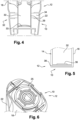
- the assistance device 10 comprises a main body 18 in which one places the dispensing device 14, and a support structure 20 against the user's skin when dispensing drops into a target organ, for example an eye.
- the support structure 20 is removably mounted on the main body 18 between an open position for inserting the dispensing device 14 and a closed position for use, for example by means of a hinge 21.
- the support structure 20 may be designed to be flexible enough to ensure the comfort of the support against the user's skin and to adapt to the reliefs in the vicinity of the target organ, and/or rigid enough to ensure the support function for the support and impose a predetermined distance between the dispensing orifice 16 and the target organ.
- the support structure 20 comprises an axial orifice 30 intended to allow the passage of drops of liquid product from the dispensing orifice 16 to the user's organ.
- the support structure 20 optionally comprises recesses 19 on two opposite sides and at its end, in particular to prevent the user's eye from being in the dark when the assistance device 10 is applied against the user's skin around his eye.
- the support structure 20 may have a closed or open contour, for example a C-shaped contour.
- the C-shaped contour allows for example the user to pull the lower eyelid through the opening of the C in order to open his eye more and ensure that the drop reaches the eye.
- the assistance device 10 also comprises a support zone 22 intended here both for gripping and for allowing the user to support it to dispense the liquid product.
- the support zone 22 is here arranged on two opposite sides of the main body 18. In another embodiment, a single support zone can be envisaged arranged on only one side of the main body 18.
- An activation pressure exerted on the support zone 22 is transmitted to the reservoir 32 of the dispensing device 14, in particular at a contact zone 29 between the reservoir and the assistance device 10.
- the support zone 22 can be made of a different material, in particular more flexible, than that of the rest of the main body 18. It can also comprise reliefs which facilitate gripping by the user.
- the assistance device 10 increases the user's gripping surface and activation pressure on the reservoir 32 compared to that of the dispensing device 14 alone, which is particularly advantageous for users suffering from neuromuscular diseases.
- the assistance device 10 further comprises inclination measuring means configured to provide information on the inclination of the distribution device 14 secured to the assistance device 10.
- the inclination measuring means comprise an inclinometer such as an electronic gyroscope or an accelerometer.
- the inclinometer is preferably placed in the main body 18, for example in an area intended to be placed in the vicinity of the dispensing nozzle.
- the assistance device 10 comprises an information processing system 23, in particular for processing information on the dispensing of a drop and on the inclination of the dispensing device 14 secured to the assistance device 10 to provide information on the quantity of liquid product dispensed.
- the information processing system 23 is a system comprising a set of components (mechanical, electronic, chemical, photonic and/or biological) capable of automatically processing information. It comprises for example a printed circuit of the PCB type (for "printed circuit board”), a set of transistors and/or a computer.
- the assistance device 10 comprises an integrated energy source, for example a portable battery, to power the various components, in particular the inclination measuring means and the information processing system 23. Alternatively, it is powered by an external power source.
- an integrated energy source for example a portable battery
- the assistance device 10 advantageously comprises means for indicating the information provided by the processing system 23, for example visual means 24, 25, sound means and/or tactile means. In the embodiment of the Figure 1A and 1B , it has a 24-inch display screen with alphanumeric information. As can be seen on the Figure 6 , the assistance device 10 further or alternatively comprises light-emitting diodes 25 around the dispensing orifice 16 making it possible to provide a light signal to indicate, for example, a good inclination or a good pressure force.
- the assistance device 10 comprises optical means 26, 28 intended to be arranged in the vicinity of the dispensing orifice 16, and configured to provide information on the dispensing of a drop of the liquid product by the dispensing device 14.
- the optical means 26, 28 here comprise an emitter 26 and a receiver 28 of an optical signal 40, configured to detect the presence of a drop disturbing the optical signal 40 and to measure the duration of this presence.
- the emitter 26 comprises for example infrared ray emitting diodes and the receiver 28 comprises for example photo-transistors capable of detecting infrared rays.
- the emitter 26 and the receiver 28 detect the presence of a drop passing through the optical signal 40 when the optical rays are disturbed, for example by a variation in the intensity of the rays.
- the emitter 26 and the receiver 28 are preferably located at a distance between 1 and 3 mm, preferably 2 mm, from the dispensing orifice 16.
- the receiver may advantageously have a reception zone extending axially and/or circumferentially and guaranteeing the detection of the passage of a drop even when the assistance device is inclined.
- the assistance device 10 comprises means for measuring the weight 33 of the dispensing device 14 secured to the assistance device 10, configured to provide information on the quantity of liquid in the reservoir 32.
- the means for measuring the weight comprise a weight sensor 33, for example of the pressure sensor type (“Force Sensing Resistor” or FSR in English), arranged below the reservoir 32 to weigh the dispensing device 14 and deduce the weight, and therefore the volume, of the quantity of liquid remaining in the reservoir 32.
- the weight sensor is located above the reservoir.
- the assistance device has several weight sensors around the reservoir in order to be able to measure the weight of the dispensing device secured to the assistance device regardless of its inclination.
- the assistance device may comprise means for detecting the dispensing device secured to the assistance device, for example a pressure sensor or an optical sensor, the information processing system being capable of confirming to the user the presence of a dispensing device and/or informing him of the absence of a dispensing device.
- the assistance device 10 and the dispensing device 14 may comprise locking means for preventing rotation of the dispensing device 14 relative to the assistance device 10.
- the locking means are particularly useful when the reservoir 32 is cylindrical.
- the locking means may comprise complementary engagement forms provided respectively on the assistance device 10 and on the dispensing device 14, for example a lug housed in a notch. Rotation being thus prevented, the user can screw the cap back onto the dispensing nozzle without the latter rotating freely.
- these locking means as opposed to a tight fit between the assist device and the dispensing device, do not prevent the measurement of the weight of the dispensing device 14.
- the contact zone 29 between the reservoir 32 and the support zone 22 of the assistance device 10 comprises means for measuring the activation pressure exerted on the contact zone 29 to trigger the optical means 26, 28 and/or provide additional information on the quantity of liquid product dispensed.
- the means for measuring the activation pressure 34 can provide information on the intensity of the activation pressure applied to the contact zone 29 and the duration of application of this activation pressure.
- the contact zone 29 is located on an internal surface of the wall of the main body 18 carrying the support zone 22.
- the means for measuring the activation pressure comprise for example a pressure sensor 34 of the FSR type, placed in contact with the reservoir 32.
- the assistance device 10 comprises means for reading information 38 carried by the dispensing device 14.
- the dispensing device 14 comprises an electronically readable information medium 36.
- This information medium is for example a radio tag 36 (RFID tag type or “radio frequency identification” in English) stuck below the reservoir 32.
- the radio tag 36 includes information such as, in this example, the filling volume of the reservoir 32 (and/or translated into the theoretical number of drops), the diameter of the dispensing orifice 16, the viscosity of the liquid product, the dosage of the liquid product, the expiry/manufacturing date.
- the reading means comprise in this example an antenna 38 capable of reading the radio tag 36 to extract the information necessary for processing the information.
- the tag can also be stuck on the side of the reservoir or at any other suitable location.
- the information processing system 23 is connected to an object external to the assistance device 10, for example to a server, a receiver, an intranet network or the internet.
- the information processing system 23 comprises storage means 39 for a variable value on the quantity of liquid product remaining in the reservoir 32.
- the presence of a drop is first detected in the vicinity of the dispensing orifice 16 using the optical means 26, 28, which triggers the measurement of the inclination of the assistance device 10.
- the information detected by the optical means 26, 28 and the inclination measuring means is then sent to the information processing system 23 which analyzes it to provide an estimate of the volume of the drop detected.
- the variation in the inclination of the assistance device 10 is first detected before triggering the switching on of the optical means 26, 28. Knowing the inclination of the assistance device 10 and the geometry of the assistance 10 and dispensing devices 14, the inclination of the dispensing device 14 is known.
- the application of this method for determining the presence of a drop during the use of the dispensing device 14 makes it possible to obtain a value representative of the quantity of liquid product dispensed drop by drop. From this value, a new residual volume value can be calculated by subtracting the estimated volume of the detected drop or the quantity of liquid product dispensed from the previous residual volume value of liquid product remaining in the reservoir 32. During a first use, the previous value of the residual volume is the filling volume of the reservoir 32.
- the residual volume value is a variable updated after the dispensing of a drop or after use (several drops dispensed) and can be stored in the storage means of the assistance device 10.
- the presence of a drop is detected by identifying a disturbance in the optical signal 40 provided by the optical means 26, 28, disturbance generated by the presence of a drop in the optical signal 40 between the transmitter 26 and the receiver 28, and more preferably, by also measuring the duration of disturbance of the optical signal 40.
- a first step consists of determining a theoretical volume of the drop, for example from information on the viscosity of the liquid product and/or the geometric characteristics of the dispensing orifice 16, or even on other characteristics of the dispensing tip.
- a method for determining the theoretical volume of a drop consists of taking as a value the volume of a drop when the dispensing device 14 is inclined at an angle ⁇ (alpha) of 90° relative to the horizontal, taking into account the diameter of the dispensing orifice 16 and the viscosity of the liquid product, two fixed parameters significantly influencing the volume of a dispensed drop.
- a fixed parameter is understood to mean a parameter which does not depend on the conditions of use of the assistance device 10, such as the inclination, the activation pressure, the pressing speed, etc. This information is for example read by the assistance device 14 on a radio tag 36 of the dispensing device 14. It is further understood that the inclination angle ⁇ corresponds to the angle formed by the axis of the dispensing device 14, corresponding to the axis of the dispensing orifice 16, relative to a horizontal direction, with reference to the direction of gravity which defines a vertical direction.
- the viscosity of the liquid product influences the volume of a dispensed drop, even without taking into account variable parameters depending on the conditions of use of the dispensing device 14.
- the volume of a drop under theoretical conditions of use increases with the viscosity of the liquid product.
- the table below is an example of correspondence between the viscosity of the liquid product and the theoretical volume of the drop. Viscosity (in Cp) 0 50 200 1000 Theoretical drop volume in ⁇ L) 40 41 42 50
- a method of weighting the theoretical volume consists, for example, in multiplying its value by a coefficient A1 linked to the inclination of the assistance device 10 and of the distribution device 14 provided by the inclination measuring means and by a coefficient A2 linked to the duration of a disturbance of an optical signal 40 provided by the optical means 26, 28 and to the viscosity of the liquid product contained in the reservoir 32.
- the inclination of the dispensing device 14 during the dispensing of a drop influences the volume of the latter.
- the volume of the dispensed drop increases with the angle of inclination ⁇ of the dispensing device 14 (on the abscissa) measured relative to the horizontal.
- a volume of 34 ⁇ l is measured at an angle of inclination ⁇ of 45°
- a volume of 37 ⁇ l at an angle of inclination ⁇ of 60°
- a volume of 40 ⁇ l at an angle of inclination ⁇ of 90°
- the liquid product used being water and the valve used being the valve V3 used as a reference.
- the information processing system 23 After receiving the inclination value provided by the inclination measuring means, the information processing system 23 calculates the coefficient A1 by dividing this inclination value by the theoretical volume of a drop of water when the dispensing device 14 is inclined at an angle ⁇ of 90° relative to the horizontal, taking the valve V3, i.e. 40 ⁇ l.
- the volume of the dispensed drop can vary with the viscosity of the liquid product depending on the speed of formation of the drop. It is therefore also interesting to weight the theoretical volume of a drop by a coefficient A2 taking into account the viscosity of the liquid product and the speed of formation of the drop. This speed of formation of the drop is advantageously obtained using the duration of disturbance of the optical signal 40 and/or the intensity and duration of the activation pressure exerted to dispense a drop.
- the table below gives an example of correspondence between a set formed by the viscosity of the liquid product and the speed of formation of the drop, and the coefficient A2.
- Speed (in s) Viscosity (in Cp) 0 50 200 1000 ⁇ 1s 0.75 0.80 1.07 1.20 A2 >2s 0.75 1.00 1.00 1.00
- the theoretical volume of a drop can also be weighted by a coefficient linked to the intensity of the activation pressure applied by the user to the reservoir 32 to cause the formation of the drop and/or the variation profile of this activation pressure over time.
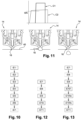
- the method begins with a first step E1 of detecting an activation pressure exerted by the user on the support zone 22, pressure which is transmitted to the reservoir 32 of the dispensing device 14 via the contact zone 29 between the latter and the assistance device 10 where an activation pressure sensor is arranged.
- a predetermined threshold for example 15N
- the optical means 26, 28 and the inclination measuring means are then activated for the detection of a drop and the measurement of the inclination of the dispensing device 14 in a step E2.
- the optical means 26, 28 monitor the drop formation zone in the vicinity of the dispensing orifice 16 until they detect the presence of a drop (step E3).
- a time counter is started in step E4 at the moment when the drop is detected. The time is counted as long as the drop does not leave the formation zone monitored by the optical means, i.e. does not detach from the dispensing orifice 16.
- the optical signal 40 of the optical means 26, 28 is modified, more precisely the optical signal 40 is no longer disturbed, and the time counter stops to provide a drop formation time to the information processing system 23 which increments the number of dispensed drops by one unit (step E6).
- the inclination measuring means provide the inclination measurements to the information processing system 23 for the estimation of the volume of the drop (step E6).
- the residual volume can be deduced therefrom, as well as the number of drops remaining in the reservoir 32. This process can be repeated several times as long as an activation pressure exceeding the predetermined threshold is detected and/or that the optical means 26, 28 detect the presence of a drop.
- FIG 11 represents a graph having time as abscissa and the intensity of the activation pressure or the disturbance of the optical signal 40 as ordinate.
- the graph is an example of representation of the information received by the information processing system 23 from the optical means 26, 28 (curve C1) and from the means for measuring the activation pressure 34 (curve C2) exerted by the user during the dispensing of a drop.
- a predetermined threshold for example 15N
- the optical means 26, 28, here the transmitter 26 and the receiver 28 of an optical signal 40 are activated.
- the optical signal 40 is disturbed, which generates a high intensity of the disturbance. This disturbance disappears once the drop detaches from the dispensing orifice 16.
- FIG. 12 Another example of a determination method is shown in Figure 12 , allowing to check the value of the residual volume calculated in step E7 of the example of the Figure 10 by measuring the weight of the distribution device 14. Steps E1 to E7 are similar to those of the example of the Figure 10 and are not taken back. Following the calculation of the residual volume in step E7, the inclination measuring means continue to provide data to the information processing system 23. The latter performs a step E8 of testing the vertical position. Once the dispensing device 14 and/or assistance device 10 returns to its rest position, the information processing system 23 validates the vertical position and a step E9 of measuring the weight of the dispensing device 14 is executed by suitable means of the assistance device 10.
- step E8 is not performed, that is to say the weight of the dispensing device 14 is measured regardless of the inclination of the dispensing device 14 and/or assistance device 10, for example after a significant variation in the inclination of the dispensing device 14 after a dispensing of drops.
- the weight measured in step E9 is different depending on the presence or absence of the cap 15 of the dispensing device 14.
- a step E10 is thus carried out to verify that the cap 15 has been replaced. This verification is either carried out manually by the user who provides this information to the assistance device 10, or more advantageously carried out by means for detecting the cap 15 located on the assistance device 10.
- the means for detecting the cap 15 may comprise, for example, a mechanical contact sensor or by the activation pressure, or more advantageously optical means.
- the information processing system 23 and/or the optical means 26, 28 can differentiate the presence of a drop of liquid or a cap 15.
- the information processing system 23 calculates, in a step E11, the quantity of liquid remaining in the reservoir 32 from the measured weight.
- step E10 of verifying the replacement of the cap 15 is carried out solely by the information processing system 23 with data calculated, preconfigured and/or read on the dispensing device 14.
- This step E10' comprises two successive sub-steps E10'a and E10'b.
- step E10'a the information processing system 23 estimates the weight of the dispensing device 14 with (respectively without) cap 15 by adding the weight of the residual volume (obtained in step E6) and the empty weight of the dispensing device 14 with (respectively without) cap 15.
- step E10'b the information processing system 23 compares the measured weight with the estimated weight of the dispensing device 14 with (respectively without) cap 15.
- the information processing system 23 deduces that the cap 15 has not been replaced on the dispensing device 14. If the measured weight is much higher than the estimated weight of the dispensing device 14 without cap 15 and/or approximately equal to the estimated weight of the dispensing device 14 with cap 15, then the system deduces that the cap 15 has been correctly replaced. Depending on the result obtained in step E10', the information processing system 23 calculates, in step E11, the quantity of liquid remaining in the reservoir 32 by subtracting the empty weight of the dispensing device 14 with or without cap 15 from the measured weight.
- the activation pressure exerted by the user on the support zone is determined by means of the means for measuring the weight of the distribution device secured to the assistance device.
- the activation pressure deforms the reservoir radially in its diameter and also longitudinally in its length. The deformation in the length can be measured by the scale and the information on the activation pressure deduced.
- the contact zone is distinct from the user's support zone.
- the invention is not limited to the embodiments shown and other embodiments will be apparent to those skilled in the art. For example, it may make different combinations of the different means presented to obtain an assistance device, a distribution kit or a determination method adapted to the need.
Landscapes
- Health & Medical Sciences (AREA)
- Engineering & Computer Science (AREA)
- Biomedical Technology (AREA)
- Heart & Thoracic Surgery (AREA)
- Life Sciences & Earth Sciences (AREA)
- Animal Behavior & Ethology (AREA)
- General Health & Medical Sciences (AREA)
- Public Health (AREA)
- Veterinary Medicine (AREA)
- General Physics & Mathematics (AREA)
- Physics & Mathematics (AREA)
- Hematology (AREA)
- Anesthesiology (AREA)
- Vascular Medicine (AREA)
- Ophthalmology & Optometry (AREA)
- Radar, Positioning & Navigation (AREA)
- Remote Sensing (AREA)
- Fluid Mechanics (AREA)
- Containers And Packaging Bodies Having A Special Means To Remove Contents (AREA)
- Medical Preparation Storing Or Oral Administration Devices (AREA)
- Automatic Analysis And Handling Materials Therefor (AREA)
- Details Of Rigid Or Semi-Rigid Containers (AREA)
- Devices For Dispensing Beverages (AREA)
- Closures For Containers (AREA)
- Loading And Unloading Of Fuel Tanks Or Ships (AREA)
Claims (15)
- Vorrichtung (10) zur Unterstützung der Verwendung einer Abgabevorrichtung (14) für ein flüssiges Produkt in Tropfenform, die ein Reservoir (32) aufweist, auf ein Organ einer Person, wobei die Unterstützungsvorrichtung (10) aufweist:- Mittel (17) zur festen Verbindung mit der Abgabevorrichtung (14),- optische Mittel (26, 28), die dazu bestimmt sind, in der Nähe einer Abgabeöffnung (16) des flüssigen Produkts angeordnet zu werden, und die eingerichtet sind, eine Information über die Abgabe eines Tropfens des flüssigen Produkts durch die Abgabevorrichtung (14) zu liefem,dadurch gekennzeichnet, dass die Unterstützungsvorrichtung (10) außerdem aufweist:- Mittel zur Messung der Neigung, die so konfiguriert sind, dass sie eine Information über die Neigung der Abgabevorrichtung (14) liefern, die fest mit der Unterstützungsvorrichtung (10) verbunden ist, undein System (23) zur Verarbeitung von Informationen über die Abgabe eines Tropfens und über die Neigung der Abgabevorrichtung (14), die fest mit der Unterstützungsvorrichtung (10) verbunden ist, um eine Information über die Menge des abgegebenen flüssigen Produkts zu liefern.
- Unterstützungsvorrichtung (10) nach dem vorhergehenden Anspruch, mit einem Kontaktbereich (29), die dazu bestimmt ist, mit dem Reservoir (32) der Abgabevorrichtung (14) in Kontakt zu sein, wenn der Benutzer Aktivierungsdruck auf das Reservoir (32) ausübt, um die Abgabe von Tropfen zu aktivieren, wobei der Kontaktbereich (29) Mittel zum Messen des Aktivierungsdrucks (34) aufweist, der auf den Kontaktbereich (29) ausgeübt wird, um die optischen Mittel (26, 28) auszulösen und/oder zusätzliche Informationen über die Menge des abgegebenen flüssigen Produkts zu liefern, vorzugsweise Informationen über die Intensität des ausgeübten Aktivierungsdrucks und die Dauer der Anwendung dieses Aktivierungsdrucks.
- Unterstützungsvorrichtung (10) nach einem der vorhergehenden Ansprüche, mit Mitteln zum Messen des Gewichts (33) der fest mit der Unterstützungsvorrichtung (10) verbundenen Abgabevorrichtung (14), die eingerichtet sind, eine Information über die Menge der Flüssigkeit im Reservoir (32) zu liefern.
- Unterstützungsvorrichtung (10) nach einem der vorhergehenden Ansprüche, wobei die optischen Mittel (26, 28) einen Sender (26) und einen Empfänger (28) für ein optisches Signal (40) aufweisen, die konfiguriert sind, die Anwesenheit eines das optische Signal (40) störenden Tropfens zu erfassen und die Dauer dieser Anwesenheit zu messen.
- Unterstützungsvorrichtung (10) nach einem der vorhergehenden Ansprüche, wobei das System (23) zur Verarbeitung von Informationen Mittel zum Lesen (38) von Informationen aufweist, die von der Ausgabevorrichtung (14) getragen werden.
- Unterstützungsvorrichtung (10) nach einem der vorhergehenden Ansprüche, bei der das System (23) zur Verarbeitung von Informationen (23) Mittel zur Speicherung (39) eines variablen Werts aufweist, der der Menge des abgegebenen flüssigen Produkts und/oder der Menge des im Reservoir (32) verbleibenden flüssigen Produkts entspricht.
- Set (12) zur Abgabe eines flüssigen Produkts in Form von Tropfen auf ein Organ einer Person, mit einer Abgabevorrichtung (14) für das flüssige Produkt und einer Unterstützungsvorrichtung (10) nach einem der vorhergehenden Ansprüche.
- Verfahren zum Bestimmen der Menge eines flüssigen Produkts, das von einer Flüssigkeitsabgabevorrichtung (14) in Form von Tropfen abgegeben wird, mithilfe einer Unterstützungsvorrichtung (10) nach einem der Ansprüche 1 bis 6, mit den folgenden Schritten:- Erfassen eines Tropfens (E3),- Schätzen des Volumens des erfassten Tropfens (E6).
- Bestimmungsverfahren nach dem vorhergehenden Anspruch, das einen Schritt (E7) zum Berechnen eines neuen Restvolumenwerts durch Subtraktion des erfassten Tropfenvolumens von dem vorherigen Restvolumenwert umfasst.
- Bestimmungsverfahren nach einem der Ansprüche 8 bis 9, wobei der Schritt des Erfassens des Tropfens (E3) einen Schritt des Identifizierens einer Störung eines optischen Signals (40), das von den optischen Mitteln (26, 28) geliefert wird, und einen Schritt des Messens der Dauer der Störung des optischen Signals (40) umfasst.
- Bestimmungsverfahren nach einem der Ansprüche 8 bis 10, bei dem der Schritt zur Schätzung des Volumens des erfassten Tropfens (E6) einen Schritt zur Bestimmung eines theoretischen Volumens dieses Tropfens umfasst, der vorzugsweise einen Schritt zur Berechnung dieses theoretischen Volumens anhand von Informationen über die Viskosität des flüssigen Produkts und/oder die geometrischen Eigenschaften der Abgabeöffnung (16) bzw. über andere Eigenschaften des Abgabeansatzes und/oder der Abgabevorrichtung (14) umfasst.
- Bestimmungsverfahren nach dem vorhergehenden Anspruch, wobei der Schritt des Schätzens des Tropfenvolumens (E6) einen Schritt des Gewichtens des erfassten Tropfenvolumens umfasst, bei dem mindestens einer der folgenden Parameter berücksichtigt wird, um die Schätzung des erfassten Tropfenvolumens zu gewichten:- die Stärke des Aktivierungsdrucks, den der Benutzer auf das Reservoir (32) ausübt, um die Bildung des Tropfens zu bewirken,- das Änderungsprofil dieses Aktivierungsdrucks über die Zeit,- die Neigung der Unterstützungsvorrichtung und/oder der Abgabevorrichtung (14),- die Dauer einer Störung eines optischen Signals (40), das von den optischen Mitteln (26, 28) geliefert wird,- die Messung des Gewichts der Abgabevorrichtung (14).
- Bestimmungsverfahren nach einem der Ansprüche 9 bis 12, umfassend einen Schritt (E9) des Messens des Gewichts der Abgabevorrichtung (14), um den berechneten Wert des Restvolumens zu validieren.
- Bestimmungsverfahren nach einem der Ansprüche 8 bis 13, umfassend einen Schritt (E10, E10') des Testens, ob eine Schutzkappe (15) auf der Abgabevorrichtung (14) vorhanden ist.
- Bestimmungsverfahren nach einem der Ansprüche 8 bis 14, wobei der Schritt des Erfassens eines Tropfens (E3) durch das Erfassen eines Aktivierungsdrucks (E1) durch einen Benutzer auf den Behälter der Abgabevorrichtung (14) ausgelöst wird, um die Abgabe von Tropfen zu aktivieren.
Applications Claiming Priority (2)
| Application Number | Priority Date | Filing Date | Title |
|---|---|---|---|
| FR1850987A FR3077488B1 (fr) | 2018-02-06 | 2018-02-06 | Dispositif d'assistance a l'utilisation d'un dispositif de distribution de produit liquide |
| PCT/EP2019/052777 WO2019154807A1 (fr) | 2018-02-06 | 2019-02-05 | Dispositif d'assistance à l'utilisation d'un dispositif de distribution de produit liquide |
Publications (2)
| Publication Number | Publication Date |
|---|---|
| EP3749262A1 EP3749262A1 (de) | 2020-12-16 |
| EP3749262B1 true EP3749262B1 (de) | 2025-05-21 |
Family
ID=62067705
Family Applications (1)
| Application Number | Title | Priority Date | Filing Date |
|---|---|---|---|
| EP19705134.5A Active EP3749262B1 (de) | 2018-02-06 | 2019-02-05 | Vorrichtung zur unterstützung der verwendung einer vorrichtung zur abgabe eines flüssigen produkts |
Country Status (9)
| Country | Link |
|---|---|
| US (1) | US12053414B2 (de) |
| EP (1) | EP3749262B1 (de) |
| JP (1) | JP7465809B2 (de) |
| CN (1) | CN111787891B (de) |
| BR (1) | BR112020015989A2 (de) |
| CA (1) | CA3089676A1 (de) |
| FR (1) | FR3077488B1 (de) |
| MX (1) | MX2020008229A (de) |
| WO (1) | WO2019154807A1 (de) |
Families Citing this family (4)
| Publication number | Priority date | Publication date | Assignee | Title |
|---|---|---|---|---|
| FR3102676B1 (fr) * | 2019-10-31 | 2023-01-06 | Nemera La Verpilliere | Dispositif d’assistance à l’utilisation d’un dispositif de distribution de produit |
| PE20220632Z (es) * | 2020-09-25 | 2022-04-26 | Burgos Alejandro Gamboa | Frasco con componentes electronicos para alojar un dispositivo de dispensacion |
| USD950712S1 (en) * | 2021-06-11 | 2022-05-03 | ChongQing Moffy Innovation Technology Co., Ltd. | Nasal irrigator |
| CN117018452B (zh) * | 2023-07-25 | 2024-08-06 | 深圳市宗匠科技有限公司 | 美容仪及其控制方法、美容装置及存储介质 |
Citations (2)
| Publication number | Priority date | Publication date | Assignee | Title |
|---|---|---|---|---|
| JP2005131887A (ja) * | 2003-10-29 | 2005-05-26 | Konica Minolta Holdings Inc | インクジェット記録装置における記録ヘッドの傾き検出方法、インクジェット記録装置における記録ヘッドのノズル列と液滴検出手段の光軸との平行度調整方法及びインクジェット記録装置 |
| JP2010145334A (ja) * | 2008-12-22 | 2010-07-01 | Tama Tlo Ltd | 流量測定装置、及び、送液ポンプ |
Family Cites Families (16)
| Publication number | Priority date | Publication date | Assignee | Title |
|---|---|---|---|---|
| US4820281A (en) * | 1987-05-21 | 1989-04-11 | Ivy Medical, Inc. | Drop volume measurement system |
| JPH0565335U (ja) | 1992-02-19 | 1993-08-31 | 信一 西尾 | 点眼用支持アダプター |
| CN1383797A (zh) | 2001-04-29 | 2002-12-11 | 李文藻 | 眼药水点滴瞄准装置 |
| US6599282B2 (en) | 2001-09-05 | 2003-07-29 | Zeev Burko | Intravenous set flow volumetric measurement device |
| JP2005140514A (ja) | 2003-11-04 | 2005-06-02 | Dkk Toa Corp | 滴下液量計測装置および方法 |
| CN101513946A (zh) | 2007-12-19 | 2009-08-26 | 罗吉多斯股份公司 | 用于分配液态产品的分配装置 |
| PT104086B (pt) * | 2008-06-05 | 2011-07-22 | Blueworks Medical Expert Diagnostics Lda | Processo para monitorização do sucesso da aplicação de um fluido a um alvo biológico não estático e sistema para sua execução |
| DE102009001860A1 (de) | 2009-03-25 | 2010-09-30 | Endress + Hauser Conducta Gesellschaft für Mess- und Regeltechnik mbH + Co. KG | Verfahren zum Bestimmen einer Anzahl von Tropfen |
| US8899453B2 (en) | 2010-05-05 | 2014-12-02 | Logidos Aps | Dispensing device for dispensing a liquid product |
| WO2014052137A1 (en) * | 2012-09-25 | 2014-04-03 | Kasthuri Perinkulam | Methods and apparatuses for measurement of liquids in motion |
| US10152867B2 (en) * | 2012-10-23 | 2018-12-11 | Kali Care, Inc. | Portable management and monitoring system for eye drop medication regiment |
| CN104853701B (zh) | 2012-11-07 | 2018-09-07 | 滴眼成像技术有限责任公司 | 执行和监控药物输送 |
| CN105163777A (zh) | 2013-02-25 | 2015-12-16 | 希福特实验室有限公司 | 用于监控通过滴注器的流体的传送的装置、方法和系统 |
| US10441214B2 (en) | 2015-01-29 | 2019-10-15 | Kali Care, Inc. | Monitoring adherence to a medication regimen using a sensor |
| DE202016003139U1 (de) * | 2015-05-22 | 2016-06-09 | 5med GmbH | Nasenapplikator |
| DK3463248T3 (da) | 2016-05-27 | 2022-10-31 | Proveris Scient Corporation | Anordnnger til anvendelse af lægemiddelanordninger |
-
2018
- 2018-02-06 FR FR1850987A patent/FR3077488B1/fr active Active
-
2019
- 2019-02-05 WO PCT/EP2019/052777 patent/WO2019154807A1/fr not_active Ceased
- 2019-02-05 CA CA3089676A patent/CA3089676A1/fr active Pending
- 2019-02-05 EP EP19705134.5A patent/EP3749262B1/de active Active
- 2019-02-05 US US16/968,015 patent/US12053414B2/en active Active
- 2019-02-05 CN CN201980016016.2A patent/CN111787891B/zh active Active
- 2019-02-05 BR BR112020015989-1A patent/BR112020015989A2/pt not_active IP Right Cessation
- 2019-02-05 JP JP2020542283A patent/JP7465809B2/ja active Active
- 2019-02-05 MX MX2020008229A patent/MX2020008229A/es unknown
Patent Citations (2)
| Publication number | Priority date | Publication date | Assignee | Title |
|---|---|---|---|---|
| JP2005131887A (ja) * | 2003-10-29 | 2005-05-26 | Konica Minolta Holdings Inc | インクジェット記録装置における記録ヘッドの傾き検出方法、インクジェット記録装置における記録ヘッドのノズル列と液滴検出手段の光軸との平行度調整方法及びインクジェット記録装置 |
| JP2010145334A (ja) * | 2008-12-22 | 2010-07-01 | Tama Tlo Ltd | 流量測定装置、及び、送液ポンプ |
Also Published As
| Publication number | Publication date |
|---|---|
| MX2020008229A (es) | 2020-11-11 |
| BR112020015989A2 (pt) | 2020-12-15 |
| FR3077488A1 (fr) | 2019-08-09 |
| CA3089676A1 (fr) | 2019-08-15 |
| US12053414B2 (en) | 2024-08-06 |
| CN111787891B (zh) | 2023-05-12 |
| JP7465809B2 (ja) | 2024-04-11 |
| US20210113372A1 (en) | 2021-04-22 |
| FR3077488B1 (fr) | 2022-02-25 |
| EP3749262A1 (de) | 2020-12-16 |
| JP2021511915A (ja) | 2021-05-13 |
| WO2019154807A1 (fr) | 2019-08-15 |
| CN111787891A (zh) | 2020-10-16 |
Similar Documents
| Publication | Publication Date | Title |
|---|---|---|
| EP3749262B1 (de) | Vorrichtung zur unterstützung der verwendung einer vorrichtung zur abgabe eines flüssigen produkts | |
| EP3749399B1 (de) | Vorrichtung zur unterstützung bei der verwendung einer axial aktivierten ausgabevorrichtung | |
| EP3305186B1 (de) | Verfahren und system zur stressüberwachung eines benutzers | |
| EP3913276B1 (de) | Druckgasbehälter, der mit einer elektronischen vorrichtung mit mitteln zur bestätigung von alarmen ausgestattet ist | |
| EP3749261B1 (de) | Vorrichtung zur unterstützung bei der verwendung einer vorrichtung zur abgabe von flüssigen produkten in form von tropfen | |
| CA3089785C (fr) | Procede de surveillance de la distribution d'une goutte et dispositif d'assistance | |
| FR2945128A1 (fr) | Dosimetre pour le traitement de radiotherapie | |
| FR3112839A1 (fr) | Récipient de fluide sous pression avec dispositif électronique permettant de calculer l’autonomie de manière plus précise | |
| EP2503150A1 (de) | Vorrichtung zur Erfassung und Messung der Rotation einer peristaltischen Pumpenschlauchkassette | |
| WO2021084093A1 (fr) | Dispositif d'assistance à l'utilisation d'un dispositif de distribution de produit | |
| WO2020030816A1 (fr) | Dispositif d'assistance à l'utilisation d'un dispositif de distribution de produit liquide | |
| WO2023152275A1 (fr) | Dispositif et procédé de mesure d'une variation de volume de produit liquide dans un conteneur | |
| EP3882507A1 (de) | Druckgasbehälter, der mit einer elektronischen vorrichtung zur warnung bei abklemmung ausgestattet ist | |
| FR3077486A1 (fr) | Dispositif d'assistance a l'utilisation d'un dispositif de distribution d'un produit | |
| FR3154481A1 (fr) | Récipient de fluide sous pression avec dispositif électronique et détection d’un dysfonctionnement du capteur de température | |
| EP2980591A1 (de) | Zähler vom typ stromzähler | |
| FR3031397A3 (fr) | Systeme et dispositif de mesure de rayonnement | |
| FR3003640A1 (fr) | Systeme de surveillance d'une quantite de rayonnement solaire recu par un utilisateur. | |
| FR2762084A1 (fr) | Dispositif et procede pour la determination des valeurs de roulage d'un support a rouler |
Legal Events
| Date | Code | Title | Description |
|---|---|---|---|
| STAA | Information on the status of an ep patent application or granted ep patent |
Free format text: STATUS: UNKNOWN |
|
| STAA | Information on the status of an ep patent application or granted ep patent |
Free format text: STATUS: THE INTERNATIONAL PUBLICATION HAS BEEN MADE |
|
| PUAI | Public reference made under article 153(3) epc to a published international application that has entered the european phase |
Free format text: ORIGINAL CODE: 0009012 |
|
| STAA | Information on the status of an ep patent application or granted ep patent |
Free format text: STATUS: REQUEST FOR EXAMINATION WAS MADE |
|
| 17P | Request for examination filed |
Effective date: 20200831 |
|
| AK | Designated contracting states |
Kind code of ref document: A1 Designated state(s): AL AT BE BG CH CY CZ DE DK EE ES FI FR GB GR HR HU IE IS IT LI LT LU LV MC MK MT NL NO PL PT RO RS SE SI SK SM TR |
|
| AX | Request for extension of the european patent |
Extension state: BA ME |
|
| DAV | Request for validation of the european patent (deleted) | ||
| DAX | Request for extension of the european patent (deleted) | ||
| STAA | Information on the status of an ep patent application or granted ep patent |
Free format text: STATUS: EXAMINATION IS IN PROGRESS |
|
| 17Q | First examination report despatched |
Effective date: 20240426 |
|
| GRAP | Despatch of communication of intention to grant a patent |
Free format text: ORIGINAL CODE: EPIDOSNIGR1 |
|
| STAA | Information on the status of an ep patent application or granted ep patent |
Free format text: STATUS: GRANT OF PATENT IS INTENDED |
|
| INTG | Intention to grant announced |
Effective date: 20241213 |
|
| GRAS | Grant fee paid |
Free format text: ORIGINAL CODE: EPIDOSNIGR3 |
|
| GRAA | (expected) grant |
Free format text: ORIGINAL CODE: 0009210 |
|
| STAA | Information on the status of an ep patent application or granted ep patent |
Free format text: STATUS: THE PATENT HAS BEEN GRANTED |
|
| AK | Designated contracting states |
Kind code of ref document: B1 Designated state(s): AL AT BE BG CH CY CZ DE DK EE ES FI FR GB GR HR HU IE IS IT LI LT LU LV MC MK MT NL NO PL PT RO RS SE SI SK SM TR |
|
| REG | Reference to a national code |
Ref country code: GB Ref legal event code: FG4D Free format text: NOT ENGLISH |
|
| REG | Reference to a national code |
Ref country code: CH Ref legal event code: EP |
|
| REG | Reference to a national code |
Ref country code: DE Ref legal event code: R096 Ref document number: 602019070202 Country of ref document: DE |
|
| REG | Reference to a national code |
Ref country code: IE Ref legal event code: FG4D Free format text: LANGUAGE OF EP DOCUMENT: FRENCH |
|
| P01 | Opt-out of the competence of the unified patent court (upc) registered |
Free format text: CASE NUMBER: APP_24817/2025 Effective date: 20250523 |
|
| REG | Reference to a national code |
Ref country code: NL Ref legal event code: MP Effective date: 20250521 |
|
| PG25 | Lapsed in a contracting state [announced via postgrant information from national office to epo] |
Ref country code: FI Free format text: LAPSE BECAUSE OF FAILURE TO SUBMIT A TRANSLATION OF THE DESCRIPTION OR TO PAY THE FEE WITHIN THE PRESCRIBED TIME-LIMIT Effective date: 20250521 Ref country code: PT Free format text: LAPSE BECAUSE OF FAILURE TO SUBMIT A TRANSLATION OF THE DESCRIPTION OR TO PAY THE FEE WITHIN THE PRESCRIBED TIME-LIMIT Effective date: 20250922 Ref country code: ES Free format text: LAPSE BECAUSE OF FAILURE TO SUBMIT A TRANSLATION OF THE DESCRIPTION OR TO PAY THE FEE WITHIN THE PRESCRIBED TIME-LIMIT Effective date: 20250521 |
|
| REG | Reference to a national code |
Ref country code: LT Ref legal event code: MG9D |
|
| PG25 | Lapsed in a contracting state [announced via postgrant information from national office to epo] |
Ref country code: NO Free format text: LAPSE BECAUSE OF FAILURE TO SUBMIT A TRANSLATION OF THE DESCRIPTION OR TO PAY THE FEE WITHIN THE PRESCRIBED TIME-LIMIT Effective date: 20250821 Ref country code: GR Free format text: LAPSE BECAUSE OF FAILURE TO SUBMIT A TRANSLATION OF THE DESCRIPTION OR TO PAY THE FEE WITHIN THE PRESCRIBED TIME-LIMIT Effective date: 20250822 |
|
| PG25 | Lapsed in a contracting state [announced via postgrant information from national office to epo] |
Ref country code: PL Free format text: LAPSE BECAUSE OF FAILURE TO SUBMIT A TRANSLATION OF THE DESCRIPTION OR TO PAY THE FEE WITHIN THE PRESCRIBED TIME-LIMIT Effective date: 20250521 Ref country code: NL Free format text: LAPSE BECAUSE OF FAILURE TO SUBMIT A TRANSLATION OF THE DESCRIPTION OR TO PAY THE FEE WITHIN THE PRESCRIBED TIME-LIMIT Effective date: 20250521 |
|
| PG25 | Lapsed in a contracting state [announced via postgrant information from national office to epo] |
Ref country code: BG Free format text: LAPSE BECAUSE OF FAILURE TO SUBMIT A TRANSLATION OF THE DESCRIPTION OR TO PAY THE FEE WITHIN THE PRESCRIBED TIME-LIMIT Effective date: 20250521 |
|
| PG25 | Lapsed in a contracting state [announced via postgrant information from national office to epo] |
Ref country code: HR Free format text: LAPSE BECAUSE OF FAILURE TO SUBMIT A TRANSLATION OF THE DESCRIPTION OR TO PAY THE FEE WITHIN THE PRESCRIBED TIME-LIMIT Effective date: 20250521 |
|
| PG25 | Lapsed in a contracting state [announced via postgrant information from national office to epo] |
Ref country code: RS Free format text: LAPSE BECAUSE OF FAILURE TO SUBMIT A TRANSLATION OF THE DESCRIPTION OR TO PAY THE FEE WITHIN THE PRESCRIBED TIME-LIMIT Effective date: 20250821 |
|
| PG25 | Lapsed in a contracting state [announced via postgrant information from national office to epo] |
Ref country code: IS Free format text: LAPSE BECAUSE OF FAILURE TO SUBMIT A TRANSLATION OF THE DESCRIPTION OR TO PAY THE FEE WITHIN THE PRESCRIBED TIME-LIMIT Effective date: 20250921 |
|
| PG25 | Lapsed in a contracting state [announced via postgrant information from national office to epo] |
Ref country code: LV Free format text: LAPSE BECAUSE OF FAILURE TO SUBMIT A TRANSLATION OF THE DESCRIPTION OR TO PAY THE FEE WITHIN THE PRESCRIBED TIME-LIMIT Effective date: 20250521 |
|
| REG | Reference to a national code |
Ref country code: AT Ref legal event code: MK05 Ref document number: 1796164 Country of ref document: AT Kind code of ref document: T Effective date: 20250521 |
|
| PG25 | Lapsed in a contracting state [announced via postgrant information from national office to epo] |
Ref country code: AT Free format text: LAPSE BECAUSE OF FAILURE TO SUBMIT A TRANSLATION OF THE DESCRIPTION OR TO PAY THE FEE WITHIN THE PRESCRIBED TIME-LIMIT Effective date: 20250521 Ref country code: DK Free format text: LAPSE BECAUSE OF FAILURE TO SUBMIT A TRANSLATION OF THE DESCRIPTION OR TO PAY THE FEE WITHIN THE PRESCRIBED TIME-LIMIT Effective date: 20250521 Ref country code: SM Free format text: LAPSE BECAUSE OF FAILURE TO SUBMIT A TRANSLATION OF THE DESCRIPTION OR TO PAY THE FEE WITHIN THE PRESCRIBED TIME-LIMIT Effective date: 20250521 |
|
| PG25 | Lapsed in a contracting state [announced via postgrant information from national office to epo] |
Ref country code: CZ Free format text: LAPSE BECAUSE OF FAILURE TO SUBMIT A TRANSLATION OF THE DESCRIPTION OR TO PAY THE FEE WITHIN THE PRESCRIBED TIME-LIMIT Effective date: 20250521 |
|
| PG25 | Lapsed in a contracting state [announced via postgrant information from national office to epo] |
Ref country code: EE Free format text: LAPSE BECAUSE OF FAILURE TO SUBMIT A TRANSLATION OF THE DESCRIPTION OR TO PAY THE FEE WITHIN THE PRESCRIBED TIME-LIMIT Effective date: 20250521 |
|
| PG25 | Lapsed in a contracting state [announced via postgrant information from national office to epo] |
Ref country code: RO Free format text: LAPSE BECAUSE OF FAILURE TO SUBMIT A TRANSLATION OF THE DESCRIPTION OR TO PAY THE FEE WITHIN THE PRESCRIBED TIME-LIMIT Effective date: 20250521 Ref country code: SK Free format text: LAPSE BECAUSE OF FAILURE TO SUBMIT A TRANSLATION OF THE DESCRIPTION OR TO PAY THE FEE WITHIN THE PRESCRIBED TIME-LIMIT Effective date: 20250521 |
|
| PG25 | Lapsed in a contracting state [announced via postgrant information from national office to epo] |
Ref country code: IT Free format text: LAPSE BECAUSE OF FAILURE TO SUBMIT A TRANSLATION OF THE DESCRIPTION OR TO PAY THE FEE WITHIN THE PRESCRIBED TIME-LIMIT Effective date: 20250521 |