EP3749210B1 - Multi-parametric tissue stiffness quantification - Google Patents
Multi-parametric tissue stiffness quantification Download PDFInfo
- Publication number
- EP3749210B1 EP3749210B1 EP19706252.4A EP19706252A EP3749210B1 EP 3749210 B1 EP3749210 B1 EP 3749210B1 EP 19706252 A EP19706252 A EP 19706252A EP 3749210 B1 EP3749210 B1 EP 3749210B1
- Authority
- EP
- European Patent Office
- Prior art keywords
- shear wave
- target tissue
- tissue
- ultrasound
- push pulse
- Prior art date
- Legal status (The legal status is an assumption and is not a legal conclusion. Google has not performed a legal analysis and makes no representation as to the accuracy of the status listed.)
- Active
Links
Images


Classifications
-
- A—HUMAN NECESSITIES
- A61—MEDICAL OR VETERINARY SCIENCE; HYGIENE
- A61B—DIAGNOSIS; SURGERY; IDENTIFICATION
- A61B8/00—Diagnosis using ultrasonic, sonic or infrasonic waves
- A61B8/48—Diagnostic techniques
- A61B8/485—Diagnostic techniques involving measuring strain or elastic properties
-
- A—HUMAN NECESSITIES
- A61—MEDICAL OR VETERINARY SCIENCE; HYGIENE
- A61B—DIAGNOSIS; SURGERY; IDENTIFICATION
- A61B8/00—Diagnosis using ultrasonic, sonic or infrasonic waves
- A61B8/08—Clinical applications
-
- A—HUMAN NECESSITIES
- A61—MEDICAL OR VETERINARY SCIENCE; HYGIENE
- A61B—DIAGNOSIS; SURGERY; IDENTIFICATION
- A61B8/00—Diagnosis using ultrasonic, sonic or infrasonic waves
- A61B8/46—Ultrasonic, sonic or infrasonic diagnostic devices with special arrangements for interfacing with the operator or the patient
- A61B8/461—Displaying means of special interest
- A61B8/463—Displaying means of special interest characterised by displaying multiple images or images and diagnostic data on one display
-
- A—HUMAN NECESSITIES
- A61—MEDICAL OR VETERINARY SCIENCE; HYGIENE
- A61B—DIAGNOSIS; SURGERY; IDENTIFICATION
- A61B8/00—Diagnosis using ultrasonic, sonic or infrasonic waves
- A61B8/52—Devices using data or image processing specially adapted for diagnosis using ultrasonic, sonic or infrasonic waves
- A61B8/5215—Devices using data or image processing specially adapted for diagnosis using ultrasonic, sonic or infrasonic waves involving processing of medical diagnostic data
- A61B8/5223—Devices using data or image processing specially adapted for diagnosis using ultrasonic, sonic or infrasonic waves involving processing of medical diagnostic data for extracting a diagnostic or physiological parameter from medical diagnostic data
-
- G—PHYSICS
- G01—MEASURING; TESTING
- G01S—RADIO DIRECTION-FINDING; RADIO NAVIGATION; DETERMINING DISTANCE OR VELOCITY BY USE OF RADIO WAVES; LOCATING OR PRESENCE-DETECTING BY USE OF THE REFLECTION OR RERADIATION OF RADIO WAVES; ANALOGOUS ARRANGEMENTS USING OTHER WAVES
- G01S7/00—Details of systems according to groups G01S13/00, G01S15/00, G01S17/00
- G01S7/52—Details of systems according to groups G01S13/00, G01S15/00, G01S17/00 of systems according to group G01S15/00
- G01S7/52017—Details of systems according to groups G01S13/00, G01S15/00, G01S17/00 of systems according to group G01S15/00 particularly adapted to short-range imaging
- G01S7/52019—Details of transmitters
- G01S7/5202—Details of transmitters for pulse systems
- G01S7/52022—Details of transmitters for pulse systems using a sequence of pulses, at least one pulse manipulating the transmissivity or reflexivity of the medium
-
- G—PHYSICS
- G01—MEASURING; TESTING
- G01S—RADIO DIRECTION-FINDING; RADIO NAVIGATION; DETERMINING DISTANCE OR VELOCITY BY USE OF RADIO WAVES; LOCATING OR PRESENCE-DETECTING BY USE OF THE REFLECTION OR RERADIATION OF RADIO WAVES; ANALOGOUS ARRANGEMENTS USING OTHER WAVES
- G01S7/00—Details of systems according to groups G01S13/00, G01S15/00, G01S17/00
- G01S7/52—Details of systems according to groups G01S13/00, G01S15/00, G01S17/00 of systems according to group G01S15/00
- G01S7/52017—Details of systems according to groups G01S13/00, G01S15/00, G01S17/00 of systems according to group G01S15/00 particularly adapted to short-range imaging
- G01S7/52023—Details of receivers
- G01S7/52036—Details of receivers using analysis of echo signal for target characterisation
- G01S7/52042—Details of receivers using analysis of echo signal for target characterisation determining elastic properties of the propagation medium or of the reflective target
-
- G—PHYSICS
- G01—MEASURING; TESTING
- G01S—RADIO DIRECTION-FINDING; RADIO NAVIGATION; DETERMINING DISTANCE OR VELOCITY BY USE OF RADIO WAVES; LOCATING OR PRESENCE-DETECTING BY USE OF THE REFLECTION OR RERADIATION OF RADIO WAVES; ANALOGOUS ARRANGEMENTS USING OTHER WAVES
- G01S7/00—Details of systems according to groups G01S13/00, G01S15/00, G01S17/00
- G01S7/52—Details of systems according to groups G01S13/00, G01S15/00, G01S17/00 of systems according to group G01S15/00
- G01S7/52017—Details of systems according to groups G01S13/00, G01S15/00, G01S17/00 of systems according to group G01S15/00 particularly adapted to short-range imaging
- G01S7/52053—Display arrangements
- G01S7/52057—Cathode ray tube displays
- G01S7/52074—Composite displays, e.g. split-screen displays; Combination of multiple images or of images and alphanumeric tabular information
-
- G—PHYSICS
- G01—MEASURING; TESTING
- G01S—RADIO DIRECTION-FINDING; RADIO NAVIGATION; DETERMINING DISTANCE OR VELOCITY BY USE OF RADIO WAVES; LOCATING OR PRESENCE-DETECTING BY USE OF THE REFLECTION OR RERADIATION OF RADIO WAVES; ANALOGOUS ARRANGEMENTS USING OTHER WAVES
- G01S7/00—Details of systems according to groups G01S13/00, G01S15/00, G01S17/00
- G01S7/52—Details of systems according to groups G01S13/00, G01S15/00, G01S17/00 of systems according to group G01S15/00
- G01S7/52017—Details of systems according to groups G01S13/00, G01S15/00, G01S17/00 of systems according to group G01S15/00 particularly adapted to short-range imaging
- G01S7/52079—Constructional features
- G01S7/52084—Constructional features related to particular user interfaces
-
- G—PHYSICS
- G06—COMPUTING OR CALCULATING; COUNTING
- G06T—IMAGE DATA PROCESSING OR GENERATION, IN GENERAL
- G06T7/00—Image analysis
- G06T7/70—Determining position or orientation of objects or cameras
-
- A—HUMAN NECESSITIES
- A61—MEDICAL OR VETERINARY SCIENCE; HYGIENE
- A61B—DIAGNOSIS; SURGERY; IDENTIFICATION
- A61B8/00—Diagnosis using ultrasonic, sonic or infrasonic waves
- A61B8/44—Constructional features of the ultrasonic, sonic or infrasonic diagnostic device
- A61B8/4405—Device being mounted on a trolley
-
- A—HUMAN NECESSITIES
- A61—MEDICAL OR VETERINARY SCIENCE; HYGIENE
- A61B—DIAGNOSIS; SURGERY; IDENTIFICATION
- A61B8/00—Diagnosis using ultrasonic, sonic or infrasonic waves
- A61B8/44—Constructional features of the ultrasonic, sonic or infrasonic diagnostic device
- A61B8/4427—Device being portable or laptop-like
-
- A—HUMAN NECESSITIES
- A61—MEDICAL OR VETERINARY SCIENCE; HYGIENE
- A61B—DIAGNOSIS; SURGERY; IDENTIFICATION
- A61B8/00—Diagnosis using ultrasonic, sonic or infrasonic waves
- A61B8/46—Ultrasonic, sonic or infrasonic diagnostic devices with special arrangements for interfacing with the operator or the patient
- A61B8/461—Displaying means of special interest
- A61B8/465—Displaying means of special interest adapted to display user selection data, e.g. icons or menus
-
- A—HUMAN NECESSITIES
- A61—MEDICAL OR VETERINARY SCIENCE; HYGIENE
- A61B—DIAGNOSIS; SURGERY; IDENTIFICATION
- A61B8/00—Diagnosis using ultrasonic, sonic or infrasonic waves
- A61B8/46—Ultrasonic, sonic or infrasonic diagnostic devices with special arrangements for interfacing with the operator or the patient
- A61B8/467—Ultrasonic, sonic or infrasonic diagnostic devices with special arrangements for interfacing with the operator or the patient characterised by special input means
- A61B8/469—Ultrasonic, sonic or infrasonic diagnostic devices with special arrangements for interfacing with the operator or the patient characterised by special input means for selection of a region of interest
-
- A—HUMAN NECESSITIES
- A61—MEDICAL OR VETERINARY SCIENCE; HYGIENE
- A61B—DIAGNOSIS; SURGERY; IDENTIFICATION
- A61B8/00—Diagnosis using ultrasonic, sonic or infrasonic waves
- A61B8/48—Diagnostic techniques
- A61B8/483—Diagnostic techniques involving the acquisition of a 3D volume of data
-
- A—HUMAN NECESSITIES
- A61—MEDICAL OR VETERINARY SCIENCE; HYGIENE
- A61B—DIAGNOSIS; SURGERY; IDENTIFICATION
- A61B8/00—Diagnosis using ultrasonic, sonic or infrasonic waves
- A61B8/52—Devices using data or image processing specially adapted for diagnosis using ultrasonic, sonic or infrasonic waves
- A61B8/5215—Devices using data or image processing specially adapted for diagnosis using ultrasonic, sonic or infrasonic waves involving processing of medical diagnostic data
- A61B8/5238—Devices using data or image processing specially adapted for diagnosis using ultrasonic, sonic or infrasonic waves involving processing of medical diagnostic data for combining image data of patient, e.g. merging several images from different acquisition modes into one image
- A61B8/5246—Devices using data or image processing specially adapted for diagnosis using ultrasonic, sonic or infrasonic waves involving processing of medical diagnostic data for combining image data of patient, e.g. merging several images from different acquisition modes into one image combining images from the same or different imaging techniques, e.g. color Doppler and B-mode
- A61B8/5253—Devices using data or image processing specially adapted for diagnosis using ultrasonic, sonic or infrasonic waves involving processing of medical diagnostic data for combining image data of patient, e.g. merging several images from different acquisition modes into one image combining images from the same or different imaging techniques, e.g. color Doppler and B-mode combining overlapping images, e.g. spatial compounding
-
- G—PHYSICS
- G01—MEASURING; TESTING
- G01S—RADIO DIRECTION-FINDING; RADIO NAVIGATION; DETERMINING DISTANCE OR VELOCITY BY USE OF RADIO WAVES; LOCATING OR PRESENCE-DETECTING BY USE OF THE REFLECTION OR RERADIATION OF RADIO WAVES; ANALOGOUS ARRANGEMENTS USING OTHER WAVES
- G01S15/00—Systems using the reflection or reradiation of acoustic waves, e.g. sonar systems
- G01S15/88—Sonar systems specially adapted for specific applications
- G01S15/89—Sonar systems specially adapted for specific applications for mapping or imaging
- G01S15/8906—Short-range imaging systems; Acoustic microscope systems using pulse-echo techniques
- G01S15/8995—Combining images from different aspect angles, e.g. spatial compounding
-
- G—PHYSICS
- G06—COMPUTING OR CALCULATING; COUNTING
- G06T—IMAGE DATA PROCESSING OR GENERATION, IN GENERAL
- G06T2200/00—Indexing scheme for image data processing or generation, in general
- G06T2200/24—Indexing scheme for image data processing or generation, in general involving graphical user interfaces [GUIs]
-
- G—PHYSICS
- G06—COMPUTING OR CALCULATING; COUNTING
- G06T—IMAGE DATA PROCESSING OR GENERATION, IN GENERAL
- G06T2207/00—Indexing scheme for image analysis or image enhancement
- G06T2207/10—Image acquisition modality
- G06T2207/10132—Ultrasound image
-
- G—PHYSICS
- G06—COMPUTING OR CALCULATING; COUNTING
- G06T—IMAGE DATA PROCESSING OR GENERATION, IN GENERAL
- G06T2207/00—Indexing scheme for image analysis or image enhancement
- G06T2207/20—Special algorithmic details
- G06T2207/20048—Transform domain processing
- G06T2207/20061—Hough transform
Definitions
- the present disclosure pertains to ultrasound systems and methods for determining stiffness levels of anisotropic tissues using shear wave elastography.
- Ultrasound shear wave elastography has been used to measure localized stiffness levels of various tissues, which may provide valuable information for detecting tissue abnormalities and diagnosing conditions such as cancer or liver fibrosis.
- Ultrasound shear wave elastography typically involves transmitting a "push pulse" from a transducer into a tissue, thereby generating a shear wave that propagates laterally therethrough. Tracking pulses emitted by the transducer can then be used to measure the velocity of the shear wave as it propagates, which usually fluctuates based on the stiffness of the tissue. For example, shear wave velocity in soft tissue is typically slower than shear wave velocity in hard tissue, assuming an identical push pulse is used to generate the shear wave in each tissue type. Accordingly, variation in shear wave velocity can be used to distinguish normal, soft tissues from abnormal, hard tissues.
- New ultrasound systems configured to determine the stiffness levels of anisotropic tissues via shear wave elastography are therefore needed.
- Document US 2018/000455 A1 discloses a method for performing shear wave ultrasound imaging based on spatial characteristics of an anisotropic medium being imaged.
- Viscoelasti city in Achilles Tendonopathy: Quantitative Assessment by Using Real-time Shear-Wave Elastography discloses a method of investigating the viscoelastic properties of a tendon using shear-wave elastography.
- the present disclosure describes systems and methods for determining stiffness levels of anisotropic tissue via shear wave ultrasound imaging.
- the anisotropic tissue e.g., skeletal muscle, evaluated according to the methods described herein may be angled with respect to a nominal axial direction of the ultrasound transducer used to interrogate the tissue.
- systems herein are configured to determine the angular orientation of the tissue and adjust the steering angle of the push pulses based on the determined orientation.
- Push pulses can be emitted at various steering angles to fully characterize the tissue, while tracking pulses arranged parallel to the push pulses monitor tissue displacement caused by the resulting shear waves.
- Displacement data acquired by the system can then be used to determine the velocity of the shear waves at various points within the tissue.
- the velocity data is indicative of the tissue stiffness.
- the system can also reconstruct all three mechanical moduli (i.e. longitudinal shear modulus, transverse shear modulus and longitudinal Young's modulus) based on multi-angle shear wave speed measurement for full characterization of the anisotropic tissue under investigation if it is transversely isotropic material (skeletal muscle is often considered transversely isotropic).
- an ultrasound imaging system for shear wave imaging is provided in claim 1.
- the processor is configured to determine the angular orientation responsive to user input. In some examples, the processor is further configured to automatically determine the angular orientation of the target tissue based on the acquired echoes. In some embodiments, the processor is configured to determine the angular orientation of the target tissue by determining the maximum intensity of backscattering signals generated at a plurality of image beam steering angles transmitted by the beamformer after compensating the beam pattern directivity. In some examples, the processor is configured to determine an angular orientation of the target tissue by performing a Hough transform on image frames generated from the acquired echoes. In some embodiments, the processor is configured to detect motion by determining tissue displacement in a lateral and an axial direction caused by the shear wave.
- the processor is configured to measure the velocity of the shear wave in the lateral and the axial direction. In some embodiments, the processor is further configured to generate a shear wave map based on the measured velocity of the shear wave, the shear wave map comprising a display of a two dimensional image of shear wave velocity values. In some embodiments, the processor is further configured to determine multiple shear wave velocities obtained at a plurality of push pulse steering angles and angular tissue orientations. In some embodiments, the processor is further configured to determine multi-parametric stiffness values of the target tissue based on the multiple shear wave velocities.
- the beamformer is configured to transmit, from the ultrasound transducer, a plurality of push pulses, each push pulse transmitted at a distinct steering angle with respect to the target tissue such that a first push pulse is transmitted parallel to the target tissue, a second push pulse is transmitted perpendicular to the target tissue, and a third push pulse is transmitted at an oblique angle with respect to the target tissue.
- a method of shear wave imaging in accordance with the present disclosure is provided in claim 12.
- the method may involve determining the angular orientation of the target tissue.
- determining the angular orientation of the target tissue comprises determining an intensity of backscattering signals generated at a plurality of image beam steering angles transmitted by the beamformer.
- detecting motion within the target tissue comprises determining tissue displacement in a lateral and an axial direction caused by the shear wave. Example methods may further involve measuring the velocity of the shear wave in the lateral and the axial direction.
- transmitting a push pulse comprises transmitting a plurality of push pulses, each push pulse transmitted at a distinct steering angle with respect to the target tissue such that a first push pulse is transmitted parallel to the target tissue, a second push pulse is transmitted perpendicular to the target tissue, and a third push pulse is transmitted at an oblique angle with respect to the target tissue.
- Embodiments may also involve determining multiple shear wave velocities obtained at a plurality of push pulse steering angles and angular tissue orientations.
- Any of the methods described herein, or steps thereof, may be embodied in non-transitory computer-readable medium comprising executable instructions, which when executed may cause a processor of a medical imaging system to perform the method or steps embodied herein.
- anisotropic tissue refers to tissue exhibiting anisotropic mechanical properties, e.g., tissue stiffness levels that vary across different directions of the tissue fibers.
- anisotropic tissue may be characterized by different stiffness values measured parallel to and perpendicular to the direction of the organized fibers comprising the tissue.
- anisotropic tissues contemplated herein include but are not limited to: muscle tissue, tendon tissue and kidney tissue. Subsets of anisotropic tissue contemplated herein include, for example, skeletal muscle tissue and myocardial tissue. For ease of description, the aforementioned tissue types will be referred to under the umbrella term "anisotropic.”
- Isotropic tissue refers to tissue exhibiting isotropic properties, e.g., tissue stiffness values that remain approximately constant across different directions of the tissue.
- FIGS. 1A and 1C show ultrasound images of anisotropic tissue comprised of two different types of skeletal muscle. As shown, the organized fibers of the two muscle types differ by the angle of the fibers with respect to the transducer used to image them.
- FIG. 1A is an ultrasound image of biceps brachii muscle fibers 102 and a shear wave tracking box 104.
- FIG. 1C is an ultrasound image of medial gastrocnemius muscle fibers 110 and a shear wave tracking box 112. In contrast to the fibers shown in FIG.
- the fibers within the tracking box 112 are arranged at an oblique angle to the lateral direction in the imaging plane of the transducer 114 shown in FIG. 1D , which is placed over a patient's calf 116.
- a push pulse transmitted into the fibers 110 (in the direction of the arrow) will pass through the fibers at an oblique angle, generating a shear wave that also propagates in the direction of the fibers. Due to the differently angled fibers in each muscle type, the shear wave propagation pattern generated by emitting a push pulse into each tissue will thus vary. As a result, the shear wave speed must be measured differently in each tissue type. Shear wave speed can be measured in the tissue of FIG.
- shear wave speed can only be accurately measured in the tissue of FIG. 1C by identifying the transverse shear modulus, longitudinal shear modulus, and longitudinal Young's modulus, which requires measuring shear wave speed in three muscle fiber orientations relative to the transducer: (1) fiber in-plane and parallel to the lateral direction, (2) fiber cross-plane perpendicular to the imaging plane, and (3) fiber in-plane with a known tilt angle.
- ultrasound-based shear wave elastography systems configured to determine tissue stiffness values in anisotropic tissues regardless of the angle of such tissues relative to the transducer.
- Systems described herein can be configured to determine the angular orientation of anisotropic tissue fibers and, based on the determined orientation, automatically conduct and/or guide a user to conduct customized shear wave elastography techniques, which can involve electronically steering push pulses and tracking beams at particular angles based on the determined fiber orientation.
- Embodiments can be further configured to perform shear wave tracking and wave speed reconstruction in a manner that is responsive to the determined fiber orientation and the parameters of the emitted ultrasound pulses. Shear wave speeds and stiffness values acquired under various acquisition conditions can be tabulated and displayed for full characterization of anisotropic tissues.
- the variability in anisotropic tissue stiffness measurements caused by different angulation can be reduced, thereby generating more accurate, standardized stiffness measurements in tissue exhibiting anisotropic mechanical properties.
- Applications of the technology described herein include detection of numerous tissue abnormalities including tumors, injuries, muscle weakness and/or fibrosis. Specific implementations may include detection of muscle diseases such as dystrophy and myositis.
- the systems described herein may be used to determine muscle stiffness in different states, e.g., active contracting state vs. passive resting.
- anisotropic tissues can be examined in the kidney cortex.
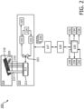
- FIG. 2 shows an example ultrasound system 200 configured to perform shear wave elastography on anisotropic tissue in accordance with the present disclosure.
- the system 200 can include an ultrasound data acquisition unit 210, which can include an ultrasound probe 211 containing an ultrasound sensor array 212 configured to transmit and receive ultrasound signals.
- the array 212 is configured to emit an ultrasonic push pulse 214 into a target region 216 containing anisotropic tissue 218, e.g., musculoskeletal tissue.
- the array 212 is also configured to transmit a plurality of tracking pulses 219 into the anisotropic tissue 218 to detect shear wave propagation after transmission of the push pulse.
- the array 212 is coupled to a transmit beamformer 221 and a multiline receive beamformer 222 via a transmit/receive (T/R) switch 223. Coordination of transmission and reception by the beamformers 221, 222 can be controlled by a beamformer controller 224.
- the multiline receive beamformer 222 can produce spatially distinct receive lines (A-lines) of echo signals, which can be processed by filtering, noise reduction, etc. by a signal processor 225.
- the components of the data acquisition unit 210 may be configured to generate a plurality of ultrasound image frames 226 from the ultrasound echoes 220 received at the array 212.
- the system 200 may also include one or more processors, such as a data processor 227, which may be configured to organize A-line data into groups and detect localized movement of the anisotropic tissue 218 based on the data embodied in each group of A-lines.
- a data processor 227 may be configured to organize A-line data into groups and detect localized movement of the anisotropic tissue 218 based on the data embodied in each group of A-lines.
- the components of the data acquisition unit 210 and the data processor 227 are configured to detect the velocity of a laterally or obliquely traveling shear wave by sensing and analyzing displacement of the anisotropic tissue 218 caused by the shear wave as it propagates through the tissue. Tracking displacement of the tissue may be achieved, in part, by time-interleaving the tracking pulses 219, for example as described in U.S. Application Publication No. 2013/0131511 Peterson et al. ).
- the system 210 also includes a display processor 228 coupled with the data processor 227 and a user interface 230.
- the display processor 228 can be configured to generate ultrasound images 232 from the image frames 226, instructions 234 for performing shear wave elastography, a shear wave region of interest tracking box graphic 236 ("ROI tracking box"), one or more automated captions 238, and a live shear wave map 239, which may be based on the measured velocity of the shear wave and comprising a display of a two dimensional image of shear wave velocity values determined by the system 200.
- the user interface 230 can be configured to display the ultrasound images 232 in real time as an ultrasound scan is being performed, and may receive user input 240 at any time before, during or after a scan.
- the configuration of the system 200 shown in FIG. 2 may vary.
- the system 200 can be portable or stationary.
- Various portable devices e.g., laptops, tablets, smart phones, or the like, may be used to implement one or more functions of the system 200.
- the ultrasound sensor array 212 may be connectable via a USB interface, for example.
- the system 200 can be configured to switch between multiple imaging and non-imaging modalities in response to receipt of the user input 240.
- One of the possible modalities includes shear wave imaging, which may contain separate sub-modalities for isotropic and anisotropic tissue elastography.
- a display screen configured to display a live ultrasound image may appear.
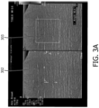
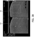
- FIGS. 3A-3C show live ultrasound image displays of anisotropic tissue imaged from different transducer orientations with respect to the fiber orientation under a selectable in-plane setting.
- the user can determine the angular orientation of the anisotropic tissue by visually inspecting the ultrasound images, e.g., B-mode images, of the tissue.
- systems herein can be configured to automatically detect the fiber orientation and then electronically steer push/tracking pulses accordingly.
- the user may be presented with an option to measure fiber orientation via visual inspection, aided by a digital angle measurement tool, or through automated orientation measurement performed by the system.
- Each of images 3A-3C shows tissue fibers arranged in a distinct angular orientation with respect to the ultrasound transducer used to image them.
- the fibers may be angled with respect to a nominal axial direction of the transducer, e.g., along the depth direction or generally perpendicular to the transducer.
- An angle measurement tool operating on the ultrasound system is configured to measure the angle of the fibers in each image 302, 304, 306 within a defined angle measurement box 303, 305, 307.
- the first image 302 shows tissue fibers oriented at approximately 90° with respect to the axial direction (or 0° with respect to the lateral direction)
- the second image 304 shows tissue fibers oriented at approximately 64° with respect to the axial direction (or 26° with respect to the lateral direction)
- the third image 306 shows tissue fibers oriented at approximately 112.9° with respect to the axial direction (or -23° with respect to lateral direction).
- an ultrasound acquisition unit e.g., unit 210
- an ultrasound acquisition unit may be utilized to transmit push pulses and tracking pulses within the tissue at particular angles based on the angular orientation of the fiber, such that the resulting shear waves propagate through the tissue in a fiber in-plane and parallel to the lateral direction, a fiber cross-plane direction, and a fiber in-plane direction at a known tilt angle.
- the system may be configured to guide the user through a customized sequence of push-pulse measurements to generate shear waves in these directions through the tissue.
- the display 400 can include a live ultrasound image 402 of the targeted tissue and a shear wave ROI tracking box 404 overlaid thereon.
- the display 400 also includes a list of instructions 406, presented as a work- or checklist, for performing a shear wave scan sequence and acquiring shear wave speed measurements in the imaging plane and transverse to the imaging plane, i.e., cross-plane.
- the display 400 can include a selectable icon for switching between the in-plane and cross-plane acquisition states.
- the system may update the instructions 406 to perform shear wave imaging at various steering angles.
- the instructions may be displayed in a checklist format, such that completion of each step is recorded in real time adjacent to each instruction.
- the default steering angle may be set at 0° in various embodiments.
- the user may initiate shear wave imaging in compliance with the instructions 406 by adjusting the steering angle of the beamformer, e.g., transmit beamformer 221.
- Embodiments can include a rotary knob or digital control for adjusting the beam steering angle.
- the geometry of the shear wave ROI tracking box 404 may change in real-time.
- a 20° beam steering angle has been specified by the user, as indicated by a caption 408 and as apparent by the tilted angle of the ROI tracking box 404.
- parallel push/tracking pulses can be transmitted into the tissue at the specified 20° angle.
- FIG. 5A shows another example of a display 500 that may be presented on a user interface.
- the display 500 includes a live ultrasound image 502 of the targeted tissue and an ROI tracking box 504 configured to change shape in response to beam steering adjustment input by a user.
- the display 500 also includes a plurality of angular beam steering status boxes 506.
- the status boxes 506 comprise thumbnail images of the targeted tissue with variously oriented ROI tracking boxes.
- the status box displaying the ROI tracking box modified to show the angle is filled in or shaded.
- the display 500 shown includes three unfilled status boxes 506, each status box representing a distinct beam steering angle to be transmitted in accordance with a customized shear wave protocol.
- FIG. 5B shows an example of a user interface 508 used to generate the display 500 shown in FIG. 5A .
- a user may be presented with a plurality of interactive buttons for measuring fiber orientation and performing shear wave elastography responsive to the detected fiber orientation.
- the user interface 508 includes a current beam steering angle 510, which in this particular example is 20°.
- the user interface 508 also displays a variety of viewing options 512, which include "Live Compare"; "Top/Bottom”; and "Left/Right.”
- embodiments of the systems described herein may also be configured to automatically measure the fiber orientation of a targeted tissue and perform a customized sequence of push/tracking pulse transmission in response to the measured fiber orientation, without user input.
- Automated fiber orientation determination and push/tracking transmission may be implemented to reduce user interaction and eliminate measurement variability.
- Systems herein can be configured to determine fiber orientation in automated fashion according to multiple techniques, which may be implemented alone or in combination. For example, fiber orientation may be determined according to image-processing based methods, e.g., edge detection and Hough transform for linear feature detection, and/or acoustic-property based methods, which may involve steering ultrasound beams into the targeted tissue at various angles and then combining the resulting images together.
- SonoCT is real-time compound imaging technology that can be employed by the systems herein to analyze ultrasound backscattering coefficient/strength.
- SonoCT may involve the transmitting ultrasound beams and receiving the corresponding ultrasound echoes at a variety of beam steering angles. From the received echoes, backscattering signal intensity within a region of interest may be determined at each angle, for example by determining the signal strength of each image on a pixel-by-pixel basis. The system can determine the peak intensity value and identify the tissue orientation angle that corresponds to the peak intensity value.
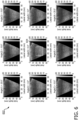
- FIGS. 6-8 An example of the compound imaging technology implemented by example systems herein is shown in FIGS. 6-8 .
- FIG. 6 shows nine B-mode ultrasound images obtained via nine distinct beam steering angles of anisotropic tissue arranged parallel to the lateral direction of the imaging plane.
- the beam steering angle used to acquire each image is indicated above each image.
- example beam steering angles may include -20°, -15°, -10°, -5°, 0°, 5°, 10°, 15°, and 20° with respect to the axial direction.
- raw radio frequency data can be acquired via an ultrasound data acquisition unit, e.g., acquisition unit 210, and analyzed for backscattering intensity within a region of interest designated by the white box 604 shown in the middle image of FIG. 6 .
- the observed backscattering intensity is the greatest in the image produced via a beam steering angle of 0° after taking into account the beam pattern directivity.
- FIG. 7 shows nine B-mode ultrasound images 702 obtained via nine distinct beam steering angles of anisotropic tissue arranged at an oblique angle of approximately -23° with respect to the lateral direction of the imaging plane.
- the beam steering angle used to acquire each image is indicated above each image.
- the example beam steering angles employed in this embodiment also include -20°, -15°, -10°, -5°, 0°, 5°, 10°, 15°, and 20°.
- the observed backscattering intensity is the greatest at the 20° beam steering angle, as shown by the white region of interest box 704.
- FIGS. 8A-8D show the results of image compounding performed by systems herein, along with a graphical representation of backscattering intensity values versus steering angle for differently oriented tissues.
- FIG. 8A shows the final angularly compounded image generated by combining the images 602 shown in FIG. 6 .
- One or more processors e.g., signal processor 225 and/or data processor 227, can be configured to compound the images and produce the image of FIG. 8A , which shows anisotropic tissue oriented parallel to the lateral direction of the imaging plane.
- FIG. 8B shows the final angularly compounded image generated by combining the images 702 shown in FIG.
- FIG. 8C shows a final angularly compounded image generated by combining a plurality of images arranged at an oblique angle of approximately 25° with respect to the lateral direction of the imaging plane.
- FIG. 8D is a line plot graphing the measured backscattering signal intensity as a function of the beam steering angle for the three angular orientations of the fiber shown in FIGS. 8A-8C .
- in-plane fiber orientations can be determined by searching for a global maximum of backscattering signal intensity detected via a plurality of transmit/receive beam steering angles. By determining the peak backscattering signal intensity, systems herein can determine the orientation of the anisotropic tissue fibers with respect to the imaging plane of the transducer used to image the fibers.
- systems herein can adjust the transmission angle of the push/tracking beams accordingly, so that push and tracking beams are transmitted at each of a (1) fiber in-plane and parallel to the lateral direction, (2) fiber cross-plane direction, and (3) fiber in-plane with a known tilt angle direction.
- the beam steering angle can be adjusted in real-time based on the fiber orientation.
- a display processor e.g., display processor 228, in cooperation with a user interface, e.g., user interface 230, can display an indication of the automated adjustment of push/tracking beams implemented by the system in a manner similar to that shown in FIGS. 4 and/or 5A.
- a shape-adjusted ROI tracking box may be displayed on a live ultrasound image. The shape of the tracking box may be adjusted as push/tracking beams are emitted at various angles with respect to the tissue.
- FIGS. 9A-9D show example ultrasound images that may be displayed to a user during transmission of the push/tracking beams into anisotropic tissue arranged at an oblique angle with respect to the lateral direction of the imaging plane.
- FIG. 9A shows a live tissue stiffness map 902 generated using a conventional push/tracking ROI configuration, i.e., not responsive to the oblique angular orientation of the tissue fibers.
- FIG. 9B shows a shear wave ROI tracking box 904 that has not been steered.
- RIG. 9C shows a shear wave tracking box 906 that has been steered to 20°
- FIG. 9D shows a shear wave tracking box that has been steered to -20°.
- full characterization of a target tissue oriented at an oblique angle with respect to the lateral direction of an ultrasound transducer imaging plane may require transmitting push pulses and tracking beams at three or more distinct transmission angles with respect to the target tissue, as illustrated in FIGS. 9B-9D .
- One push/tracking sequence may be transmitted approximately parallel to the target tissue
- a second push/tracking sequence may be transmitted at an approximately perpendicular angle with respect to the target tissue
- a third push/tracking sequence may be transmitted at a specified tilt angle with respect to the target tissue.
- the specified tilt angle is determined based on the angular orientation of the fiber determined either visually or in automated fashion.
- Each distinct steering angle will generate a shear wave that propagates in a different direction within the target tissue.
- the tissue stiffness map 902 shown in FIG. 9A may also be displayed concurrently with the live ultrasound images shown in each of FIGS. 9B-9C , for example superimposed on top of or adjacent to the ROI tracking box.
- the stiffness map may be updated in real time as the ultrasound transducer and/or tissue fiber is moved or as differently-steered push/tracking beams are emitted.
- Systems herein are configured to reconstruct the stiffness map in accordance with the steering angle of the beamformer.
- a user interface may receive a user input, e.g., "Save" or "Stop,” instructing the system to measure the absolute stiffness of a sub-region or point within the ROI tracking box, which may also be defined by the user.
- the shape and size of the subregions may vary.
- Stiffness measurements can be stored in a memory and displayed in a final report, e.g., report 1000 as shown in FIG. 10 , in conjunction with the acquisition conditions employed to acquire the measurements.
- Adjustment of the ROI tracking boxes shown in FIGS. 9A-9D (and 5A) represents beam steering performed by multiple system components described herein.
- the transmit beamformer e.g., beamformer 221
- a controller e.g., beamformer controller 224
- Tracking beams used to monitor tissue displacement caused by the resulting shear wave can be emitted at the same transmission angle, i.e., parallel to the push pulse.
- a receive beamformer e.g., multiline receive beamformer 222, can then receive echoes responsive to the transmitted tracking beams.
- the tracking beams are aligned with the push pulse direction so that resulting tissue motion is aligned with the acoustic beam axis for optimal motion signal-to-noise ratio.
- systems described herein can be configured to process the information received by a data acquisition unit (via the receive beamformer) to reconstruct shear wave speed in a manner that accounts for the steering of the push pulses and tracking beams.
- the system can be configured to convert ultrasound scanning data of shear wave-induced tissue displacement to scanning data of shear wave-induced tissue displacement measured at a particular angle with respect to the imaging plane of the ultrasound transducer.
- One or more processors can also be configured to perform shear wave speed vector estimation in both the lateral and axial direction to account for the true propagation angle of the shear wave.
- Shear wave speed reconstruction can then be performed by combining the lateral and axial velocity components into a true, composite shear wave velocity, thus accounting for the fact that shear wave generated by an angular push pulse will displace tissue in both the axial and lateral direction.
- systems here are configured to reconstruct the shear wave velocity in a manner that is adaptive to the steering angle of the push and tracking pulses used to generate the shear wave.
- the final shear wave reconstruction can be determined by combining the underlying shear wave propagation pattern, push/tracking steering angle, and the angular orientation of the fiber with respect to the imaging plane of the ultrasound probe.
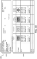
- FIG. 10 is an example report 1000 generated and displayed in accordance with principles of the present disclosure.
- the report 1000 may include a variety of patient demographic information 1002 and shear wave tissue characterization information 1004.
- the characterization information 1004 can be categorized according to the angular orientation of the target tissue and/or the steering angle of the beamformer.
- the information 1004 can include whether the ultrasound transducer used to perform shear wave imaging transmitted push pulses in-plane, cross-plane, in-plane at a steered angle, or in-plane against obliquely oriented target tissue.
- the information 1004 may also include, for each steering angle and/or fiber orientation, an average shear wave speed, a shear wave speed standard deviation, a median shear wave speed, and an interquartile range of the shear wave speed.
- the orientation angle of the fibers comprising the target tissue can be displayed, along with the steering angle of the push pulses/tracking beams.
- shear wave information obtained via a variety of fiber orientations and steering angles, multi-parametric stiffness quantification of the target tissue is embodied in the report 1000.
- This information may improve the accuracy of the tissue stiffness assessment performed by a user, e.g., a radiologist, by revealing differences in shear wave propagation across different fiber orientations.
- the shear wave imaging conditions used to obtain the stiffness quantifications may be repeated upon subsequent examinations, thereby enabling a consistent, standardized tissue interrogation technique.
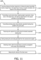
- FIG. 11 is a flow diagram of a method of shear wave imaging performed in accordance with principles of the present disclosure.
- the example method 1100 shows the steps that may be utilized , in any sequence, by the systems and/or apparatuses described herein.
- the method 1100 may be performed by an ultrasound imaging system, such as system 100, or other systems including, for example, a mobile system such as LUMIFY by Koninklijke Philips N.V. ("Philips"). Additional example systems may include SPARQ and/or EPIQ, also produced by Philips.
- the method 1100 begins at block 1102 by "acquiring ultrasound echoes responsive to ultrasound pulses transmitted toward a target tissue, the target tissue having an angular orientation with respect to the ultrasound transducer.”
- the method involves "transmitting a push pulse along a steering angle to generate a shear wave in the target tissue, the steering angle based on the angular orientation of the target tissue.”
- the method involves "transmitting tracking pulses along laterally separated tracking lines parallel to the push pulse.”
- the method involves "receiving echo signals from points along the laterally separated tracking lines.”
- the method involves "storing tracking line echo data generated from the received echo signals.”
- the method involves "detecting motion within the target tissue caused by propagation of the shear wave therethrough.”
- the method involves "measuring the velocity of the shear wave.”
- a programmable device such as a computer-based system or programmable logic
- the above-described systems and methods can be implemented using any of various known or later developed programming languages, such as "C”, “C++”, “FORTRAN”, “Pascal”, “VHDL” and the like.
- various storage media such as magnetic computer disks, optical disks, electronic memories and the like, can be prepared that can contain information that can direct a device, such as a computer, to implement the above-described systems and/or methods.
- the storage media can provide the information and programs to the device, thus enabling the device to perform functions of the systems and/or methods described herein.
- the computer could receive the information, appropriately configure itself and perform the functions of the various systems and methods outlined in the diagrams and flowcharts above to implement the various functions. That is, the computer could receive various portions of information from the disk relating to different elements of the above-described systems and/or methods, implement the individual systems and/or methods and coordinate the functions of the individual systems and/or methods described above.
- processors described herein can be implemented in hardware, software and firmware. Further, the various methods and parameters are included by way of example only and not in any limiting sense. In view of this disclosure, those of ordinary skill in the art can implement the present teachings in determining their own techniques and needed equipment to affect these techniques, while remaining within the scope of the invention.
- the functionality of one or more of the processors described herein may be incorporated into a fewer number or a single processing unit (e.g., a CPU) and may be implemented using application specific integrated circuits (ASICs) or general purpose processing circuits which are programmed responsive to executable instruction to perform the functions described herein.
- ASICs application specific integrated circuits
- the present system may have been described with particular reference to an ultrasound imaging system, it is also envisioned that the present system can be extended to other medical imaging systems where one or more images are obtained in a systematic manner. Accordingly, the present system may be used to obtain and/or record image information related to, but not limited to renal, testicular, breast, ovarian, uterine, thyroid, hepatic, lung, musculoskeletal, splenic, cardiac, arterial and vascular systems, as well as other imaging applications related to ultrasound-guided interventions. Further, the present system may also include one or more programs which may be used with conventional imaging systems so that they may provide features and advantages of the present system.
Landscapes
- Engineering & Computer Science (AREA)
- Health & Medical Sciences (AREA)
- Life Sciences & Earth Sciences (AREA)
- Physics & Mathematics (AREA)
- Radar, Positioning & Navigation (AREA)
- Remote Sensing (AREA)
- General Physics & Mathematics (AREA)
- Computer Networks & Wireless Communication (AREA)
- Biophysics (AREA)
- Heart & Thoracic Surgery (AREA)
- Veterinary Medicine (AREA)
- Public Health (AREA)
- General Health & Medical Sciences (AREA)
- Nuclear Medicine, Radiotherapy & Molecular Imaging (AREA)
- Pathology (AREA)
- Radiology & Medical Imaging (AREA)
- Biomedical Technology (AREA)
- Animal Behavior & Ethology (AREA)
- Medical Informatics (AREA)
- Molecular Biology (AREA)
- Surgery (AREA)
- Acoustics & Sound (AREA)
- Computer Vision & Pattern Recognition (AREA)
- Theoretical Computer Science (AREA)
- Physiology (AREA)
- Human Computer Interaction (AREA)
- Ultra Sonic Daignosis Equipment (AREA)
Applications Claiming Priority (2)
| Application Number | Priority Date | Filing Date | Title |
|---|---|---|---|
| US201862628323P | 2018-02-09 | 2018-02-09 | |
| PCT/EP2019/053218 WO2019155037A1 (en) | 2018-02-09 | 2019-02-09 | Multi-parametric tissue stiffness quantification |
Publications (2)
| Publication Number | Publication Date |
|---|---|
| EP3749210A1 EP3749210A1 (en) | 2020-12-16 |
| EP3749210B1 true EP3749210B1 (en) | 2023-11-29 |
Family
ID=65496744
Family Applications (1)
| Application Number | Title | Priority Date | Filing Date |
|---|---|---|---|
| EP19706252.4A Active EP3749210B1 (en) | 2018-02-09 | 2019-02-09 | Multi-parametric tissue stiffness quantification |
Country Status (5)
| Country | Link |
|---|---|
| US (1) | US20210361262A1 (https=) |
| EP (1) | EP3749210B1 (https=) |
| JP (1) | JP7237079B2 (https=) |
| CN (1) | CN111698947B (https=) |
| WO (1) | WO2019155037A1 (https=) |
Families Citing this family (9)
| Publication number | Priority date | Publication date | Assignee | Title |
|---|---|---|---|---|
| EP3826542B1 (en) | 2018-07-24 | 2023-11-29 | Koninklijke Philips N.V. | Ultrasound system and method for guided shear wave elastography of anisotropic tissue |
| JP7033692B6 (ja) | 2018-08-29 | 2022-05-30 | コーニンクレッカ フィリップス エヌ ヴェ | スマート剪断波エラストグラフィのための超音波システムと方法 |
| US20200077986A1 (en) * | 2018-09-12 | 2020-03-12 | Siemens Medical Solutions Usa, Inc. | Angles for ultrasound-based shear wave imaging |
| US11678862B2 (en) * | 2019-09-16 | 2023-06-20 | Siemens Medical Solutions Usa, Inc. | Muscle contraction state triggering of quantitative medical diagnostic ultrasound |
| CN113633312B (zh) * | 2020-05-11 | 2024-10-25 | 深圳迈瑞生物医疗电子股份有限公司 | 超声弹性成像方法和系统 |
| FR3114155B1 (fr) * | 2020-09-15 | 2022-07-29 | Supersonic Imagine | Procédé et système de caractérisation ultrasonore d’un milieu |
| CN112674791B (zh) * | 2020-11-30 | 2023-08-29 | 深圳大学 | 肌肉超声弹性成像的优化方法及系统 |
| US12396702B2 (en) * | 2020-12-17 | 2025-08-26 | Koninklijke Philips N.V. | Systems, methods, and apparatuses for quantitative assessment of organ mobility |
| US20240057970A1 (en) * | 2020-12-30 | 2024-02-22 | Koninklijke Philips N.V. | Ultrasound image acquisition, tracking and review |
Family Cites Families (17)
| Publication number | Priority date | Publication date | Assignee | Title |
|---|---|---|---|---|
| US6468218B1 (en) * | 2001-08-31 | 2002-10-22 | Siemens Medical Systems, Inc. | 3-D ultrasound imaging system and method |
| KR101121289B1 (ko) * | 2009-08-25 | 2012-03-23 | 삼성메디슨 주식회사 | 영상 파라미터를 설정하는 초음파 시스템 및 방법 |
| EP2504716B1 (en) * | 2009-11-25 | 2014-07-30 | Koninklijke Philips N.V. | Ultrasonic shear wave imaging with focused scanline beamforming |
| US10448924B2 (en) * | 2010-12-13 | 2019-10-22 | Koninklijke Philips N.V. | Ultrasonic acoustic radiation force excitation for ultrasonic material property measurement and imaging |
| US20120253194A1 (en) * | 2011-03-30 | 2012-10-04 | Tadashi Tamura | Methods and apparatus for ultrasound imaging |
| JP5846411B2 (ja) * | 2011-06-16 | 2016-01-20 | 学校法人上智学院 | イメージング方法及び変位計測方法及び装置、並びに、超音波画像診断装置 |
| RU2610884C2 (ru) * | 2011-09-30 | 2017-02-17 | Конинклейке Филипс Н.В. | Ультразвуковая система с динамически автоматизированной установкой параметров потоковой допплерографии при движении контрольного объема |
| WO2013046087A1 (en) * | 2011-09-30 | 2013-04-04 | Koninklijke Philips Electronics N.V. | Ultrasound system with automated doppler flow settings. |
| US8891881B2 (en) * | 2012-01-25 | 2014-11-18 | General Electric Company | System and method for identifying an optimal image frame for ultrasound imaging |
| US9220479B2 (en) * | 2012-03-30 | 2015-12-29 | Hitachi Aloka Medical, Ltd. | Methods and apparatus for ultrasound imaging |
| CN104684488B (zh) * | 2012-09-27 | 2017-08-15 | 皇家飞利浦有限公司 | 用于超声狭窄评估的自动双平面‑pw工作流程 |
| CN103845075B (zh) * | 2012-11-30 | 2016-09-28 | 通用电气公司 | 超声装置及超声成像方法 |
| EP3066643B1 (en) * | 2013-11-05 | 2020-05-27 | Koninklijke Philips N.V. | Automated segmentation of tri-plane images for real time ultrasonic imaging |
| EP3160358B1 (en) * | 2014-06-30 | 2020-08-05 | Koninklijke Philips N.V. | Ultrasound shear wave elastography featuring therapy monitoring |
| BR112017013861B1 (pt) * | 2014-12-24 | 2022-07-12 | Supersonic Imagine | Método para elastrografia de onda de cisalhamento para geração de imagem de um campo de observação em um meio anisotrópico e aparelho de geração de imagem para a implementação do método |
| US11445914B2 (en) * | 2016-05-13 | 2022-09-20 | The University Of North Carolina At Chapel Hill | Methods and systems for assessing material anisotropy and other characteristics |
| EP3563769B1 (en) * | 2018-04-30 | 2024-12-11 | ESAOTE S.p.A. | Method and ultrasound system for shear wave elasticity imaging |
-
2019
- 2019-02-09 EP EP19706252.4A patent/EP3749210B1/en active Active
- 2019-02-09 US US16/968,313 patent/US20210361262A1/en not_active Abandoned
- 2019-02-09 WO PCT/EP2019/053218 patent/WO2019155037A1/en not_active Ceased
- 2019-02-09 CN CN201980012260.1A patent/CN111698947B/zh active Active
- 2019-02-09 JP JP2020542389A patent/JP7237079B2/ja active Active
Also Published As
| Publication number | Publication date |
|---|---|
| CN111698947A (zh) | 2020-09-22 |
| JP2021512699A (ja) | 2021-05-20 |
| JP7237079B2 (ja) | 2023-03-10 |
| US20210361262A1 (en) | 2021-11-25 |
| CN111698947B (zh) | 2024-09-03 |
| EP3749210A1 (en) | 2020-12-16 |
| WO2019155037A1 (en) | 2019-08-15 |
Similar Documents
| Publication | Publication Date | Title |
|---|---|---|
| EP3749210B1 (en) | Multi-parametric tissue stiffness quantification | |
| RU2667617C2 (ru) | Система и способ эластографических измерений | |
| US8475382B2 (en) | Ultrasound diagnostic apparatus and method for tracing movement of tissue | |
| US20190216423A1 (en) | Ultrasound imaging apparatus and method of controlling the same | |
| CN112437634B (zh) | 智能导波弹性成像 | |
| US20120108972A1 (en) | Ultrasound diagnostic apparatus and method for tracing movement of tissue | |
| KR20140020486A (ko) | 초음파를 이용하여 조직의 탄성을 분석하는 방법 및 장치 | |
| JP2021522011A (ja) | 超音波スクリーニングのためのシステム及び方法 | |
| US20180168550A1 (en) | Ultrasound imaging apparatus and method of controlling the same | |
| US8348848B1 (en) | Methods and apparatus for ultrasound imaging | |
| US11219429B2 (en) | Ultrasound imaging apparatus and controlling method for the same | |
| JP7261870B2 (ja) | 超音波画像内のツールを追跡するためのシステム及び方法 | |
| EP3685753B1 (en) | Ultrasound imaging apparatus and method of controlling the same | |
| KR102749835B1 (ko) | 초음파 영상 장치 및 그 제어방법 | |
| CN112672696B (zh) | 用于跟踪超声图像中的工具的系统和方法 | |
| US20170156702A1 (en) | Ultrasonic diagnostic apparatus and method for controlling the same | |
| US12611165B2 (en) | Fetal ultrasound image processing | |
| Dickie et al. | A flexible research interface for collecting clinical ultrasound images | |
| Pelissiera et al. | A Flexible Research Interface for Collecting Clinical Ultrasound |
Legal Events
| Date | Code | Title | Description |
|---|---|---|---|
| STAA | Information on the status of an ep patent application or granted ep patent |
Free format text: STATUS: UNKNOWN |
|
| STAA | Information on the status of an ep patent application or granted ep patent |
Free format text: STATUS: THE INTERNATIONAL PUBLICATION HAS BEEN MADE |
|
| PUAI | Public reference made under article 153(3) epc to a published international application that has entered the european phase |
Free format text: ORIGINAL CODE: 0009012 |
|
| STAA | Information on the status of an ep patent application or granted ep patent |
Free format text: STATUS: REQUEST FOR EXAMINATION WAS MADE |
|
| 17P | Request for examination filed |
Effective date: 20200909 |
|
| AK | Designated contracting states |
Kind code of ref document: A1 Designated state(s): AL AT BE BG CH CY CZ DE DK EE ES FI FR GB GR HR HU IE IS IT LI LT LU LV MC MK MT NL NO PL PT RO RS SE SI SK SM TR |
|
| AX | Request for extension of the european patent |
Extension state: BA ME |
|
| DAV | Request for validation of the european patent (deleted) | ||
| DAX | Request for extension of the european patent (deleted) | ||
| GRAP | Despatch of communication of intention to grant a patent |
Free format text: ORIGINAL CODE: EPIDOSNIGR1 |
|
| STAA | Information on the status of an ep patent application or granted ep patent |
Free format text: STATUS: GRANT OF PATENT IS INTENDED |
|
| INTG | Intention to grant announced |
Effective date: 20230626 |
|
| GRAS | Grant fee paid |
Free format text: ORIGINAL CODE: EPIDOSNIGR3 |
|
| GRAA | (expected) grant |
Free format text: ORIGINAL CODE: 0009210 |
|
| STAA | Information on the status of an ep patent application or granted ep patent |
Free format text: STATUS: THE PATENT HAS BEEN GRANTED |
|
| AK | Designated contracting states |
Kind code of ref document: B1 Designated state(s): AL AT BE BG CH CY CZ DE DK EE ES FI FR GB GR HR HU IE IS IT LI LT LU LV MC MK MT NL NO PL PT RO RS SE SI SK SM TR |
|
| REG | Reference to a national code |
Ref country code: GB Ref legal event code: FG4D |
|
| REG | Reference to a national code |
Ref country code: CH Ref legal event code: EP |
|
| REG | Reference to a national code |
Ref country code: DE Ref legal event code: R096 Ref document number: 602019042307 Country of ref document: DE |
|
| REG | Reference to a national code |
Ref country code: IE Ref legal event code: FG4D |
|
| REG | Reference to a national code |
Ref country code: DE Ref legal event code: R084 Ref document number: 602019042307 Country of ref document: DE |
|
| REG | Reference to a national code |
Ref country code: GB Ref legal event code: 746 Effective date: 20240117 |
|
| REG | Reference to a national code |
Ref country code: LT Ref legal event code: MG9D |
|
| REG | Reference to a national code |
Ref country code: NL Ref legal event code: MP Effective date: 20231129 |
|
| PG25 | Lapsed in a contracting state [announced via postgrant information from national office to epo] |
Ref country code: GR Free format text: LAPSE BECAUSE OF FAILURE TO SUBMIT A TRANSLATION OF THE DESCRIPTION OR TO PAY THE FEE WITHIN THE PRESCRIBED TIME-LIMIT Effective date: 20240301 |
|
| PG25 | Lapsed in a contracting state [announced via postgrant information from national office to epo] |
Ref country code: IS Free format text: LAPSE BECAUSE OF FAILURE TO SUBMIT A TRANSLATION OF THE DESCRIPTION OR TO PAY THE FEE WITHIN THE PRESCRIBED TIME-LIMIT Effective date: 20240329 |
|
| PG25 | Lapsed in a contracting state [announced via postgrant information from national office to epo] |
Ref country code: LT Free format text: LAPSE BECAUSE OF FAILURE TO SUBMIT A TRANSLATION OF THE DESCRIPTION OR TO PAY THE FEE WITHIN THE PRESCRIBED TIME-LIMIT Effective date: 20231129 |
|
| PG25 | Lapsed in a contracting state [announced via postgrant information from national office to epo] |
Ref country code: ES Free format text: LAPSE BECAUSE OF FAILURE TO SUBMIT A TRANSLATION OF THE DESCRIPTION OR TO PAY THE FEE WITHIN THE PRESCRIBED TIME-LIMIT Effective date: 20231129 |
|
| PG25 | Lapsed in a contracting state [announced via postgrant information from national office to epo] |
Ref country code: LT Free format text: LAPSE BECAUSE OF FAILURE TO SUBMIT A TRANSLATION OF THE DESCRIPTION OR TO PAY THE FEE WITHIN THE PRESCRIBED TIME-LIMIT Effective date: 20231129 Ref country code: IS Free format text: LAPSE BECAUSE OF FAILURE TO SUBMIT A TRANSLATION OF THE DESCRIPTION OR TO PAY THE FEE WITHIN THE PRESCRIBED TIME-LIMIT Effective date: 20240329 Ref country code: GR Free format text: LAPSE BECAUSE OF FAILURE TO SUBMIT A TRANSLATION OF THE DESCRIPTION OR TO PAY THE FEE WITHIN THE PRESCRIBED TIME-LIMIT Effective date: 20240301 Ref country code: ES Free format text: LAPSE BECAUSE OF FAILURE TO SUBMIT A TRANSLATION OF THE DESCRIPTION OR TO PAY THE FEE WITHIN THE PRESCRIBED TIME-LIMIT Effective date: 20231129 Ref country code: BG Free format text: LAPSE BECAUSE OF FAILURE TO SUBMIT A TRANSLATION OF THE DESCRIPTION OR TO PAY THE FEE WITHIN THE PRESCRIBED TIME-LIMIT Effective date: 20240229 |
|
| REG | Reference to a national code |
Ref country code: AT Ref legal event code: MK05 Ref document number: 1635257 Country of ref document: AT Kind code of ref document: T Effective date: 20231129 |
|
| PG25 | Lapsed in a contracting state [announced via postgrant information from national office to epo] |
Ref country code: NL Free format text: LAPSE BECAUSE OF FAILURE TO SUBMIT A TRANSLATION OF THE DESCRIPTION OR TO PAY THE FEE WITHIN THE PRESCRIBED TIME-LIMIT Effective date: 20231129 |
|
| PG25 | Lapsed in a contracting state [announced via postgrant information from national office to epo] |
Ref country code: SE Free format text: LAPSE BECAUSE OF FAILURE TO SUBMIT A TRANSLATION OF THE DESCRIPTION OR TO PAY THE FEE WITHIN THE PRESCRIBED TIME-LIMIT Effective date: 20231129 Ref country code: RS Free format text: LAPSE BECAUSE OF FAILURE TO SUBMIT A TRANSLATION OF THE DESCRIPTION OR TO PAY THE FEE WITHIN THE PRESCRIBED TIME-LIMIT Effective date: 20231129 Ref country code: PL Free format text: LAPSE BECAUSE OF FAILURE TO SUBMIT A TRANSLATION OF THE DESCRIPTION OR TO PAY THE FEE WITHIN THE PRESCRIBED TIME-LIMIT Effective date: 20231129 Ref country code: NO Free format text: LAPSE BECAUSE OF FAILURE TO SUBMIT A TRANSLATION OF THE DESCRIPTION OR TO PAY THE FEE WITHIN THE PRESCRIBED TIME-LIMIT Effective date: 20240229 Ref country code: NL Free format text: LAPSE BECAUSE OF FAILURE TO SUBMIT A TRANSLATION OF THE DESCRIPTION OR TO PAY THE FEE WITHIN THE PRESCRIBED TIME-LIMIT Effective date: 20231129 Ref country code: LV Free format text: LAPSE BECAUSE OF FAILURE TO SUBMIT A TRANSLATION OF THE DESCRIPTION OR TO PAY THE FEE WITHIN THE PRESCRIBED TIME-LIMIT Effective date: 20231129 Ref country code: HR Free format text: LAPSE BECAUSE OF FAILURE TO SUBMIT A TRANSLATION OF THE DESCRIPTION OR TO PAY THE FEE WITHIN THE PRESCRIBED TIME-LIMIT Effective date: 20231129 |
|
| PGFP | Annual fee paid to national office [announced via postgrant information from national office to epo] |
Ref country code: FR Payment date: 20240226 Year of fee payment: 6 |
|
| PG25 | Lapsed in a contracting state [announced via postgrant information from national office to epo] |
Ref country code: DK Free format text: LAPSE BECAUSE OF FAILURE TO SUBMIT A TRANSLATION OF THE DESCRIPTION OR TO PAY THE FEE WITHIN THE PRESCRIBED TIME-LIMIT Effective date: 20231129 |
|
| PG25 | Lapsed in a contracting state [announced via postgrant information from national office to epo] |
Ref country code: CZ Free format text: LAPSE BECAUSE OF FAILURE TO SUBMIT A TRANSLATION OF THE DESCRIPTION OR TO PAY THE FEE WITHIN THE PRESCRIBED TIME-LIMIT Effective date: 20231129 Ref country code: AT Free format text: LAPSE BECAUSE OF FAILURE TO SUBMIT A TRANSLATION OF THE DESCRIPTION OR TO PAY THE FEE WITHIN THE PRESCRIBED TIME-LIMIT Effective date: 20231129 |
|
| PG25 | Lapsed in a contracting state [announced via postgrant information from national office to epo] |
Ref country code: SK Free format text: LAPSE BECAUSE OF FAILURE TO SUBMIT A TRANSLATION OF THE DESCRIPTION OR TO PAY THE FEE WITHIN THE PRESCRIBED TIME-LIMIT Effective date: 20231129 |
|
| PG25 | Lapsed in a contracting state [announced via postgrant information from national office to epo] |
Ref country code: SM Free format text: LAPSE BECAUSE OF FAILURE TO SUBMIT A TRANSLATION OF THE DESCRIPTION OR TO PAY THE FEE WITHIN THE PRESCRIBED TIME-LIMIT Effective date: 20231129 Ref country code: SK Free format text: LAPSE BECAUSE OF FAILURE TO SUBMIT A TRANSLATION OF THE DESCRIPTION OR TO PAY THE FEE WITHIN THE PRESCRIBED TIME-LIMIT Effective date: 20231129 Ref country code: RO Free format text: LAPSE BECAUSE OF FAILURE TO SUBMIT A TRANSLATION OF THE DESCRIPTION OR TO PAY THE FEE WITHIN THE PRESCRIBED TIME-LIMIT Effective date: 20231129 Ref country code: IT Free format text: LAPSE BECAUSE OF FAILURE TO SUBMIT A TRANSLATION OF THE DESCRIPTION OR TO PAY THE FEE WITHIN THE PRESCRIBED TIME-LIMIT Effective date: 20231129 Ref country code: EE Free format text: LAPSE BECAUSE OF FAILURE TO SUBMIT A TRANSLATION OF THE DESCRIPTION OR TO PAY THE FEE WITHIN THE PRESCRIBED TIME-LIMIT Effective date: 20231129 Ref country code: DK Free format text: LAPSE BECAUSE OF FAILURE TO SUBMIT A TRANSLATION OF THE DESCRIPTION OR TO PAY THE FEE WITHIN THE PRESCRIBED TIME-LIMIT Effective date: 20231129 Ref country code: CZ Free format text: LAPSE BECAUSE OF FAILURE TO SUBMIT A TRANSLATION OF THE DESCRIPTION OR TO PAY THE FEE WITHIN THE PRESCRIBED TIME-LIMIT Effective date: 20231129 Ref country code: AT Free format text: LAPSE BECAUSE OF FAILURE TO SUBMIT A TRANSLATION OF THE DESCRIPTION OR TO PAY THE FEE WITHIN THE PRESCRIBED TIME-LIMIT Effective date: 20231129 |
|
| PG25 | Lapsed in a contracting state [announced via postgrant information from national office to epo] |
Ref country code: PT Free format text: LAPSE BECAUSE OF FAILURE TO SUBMIT A TRANSLATION OF THE DESCRIPTION OR TO PAY THE FEE WITHIN THE PRESCRIBED TIME-LIMIT Effective date: 20240401 |
|
| PG25 | Lapsed in a contracting state [announced via postgrant information from national office to epo] |
Ref country code: PT Free format text: LAPSE BECAUSE OF FAILURE TO SUBMIT A TRANSLATION OF THE DESCRIPTION OR TO PAY THE FEE WITHIN THE PRESCRIBED TIME-LIMIT Effective date: 20240401 |
|
| REG | Reference to a national code |
Ref country code: DE Ref legal event code: R097 Ref document number: 602019042307 Country of ref document: DE |
|
| PG25 | Lapsed in a contracting state [announced via postgrant information from national office to epo] |
Ref country code: MC Free format text: LAPSE BECAUSE OF FAILURE TO SUBMIT A TRANSLATION OF THE DESCRIPTION OR TO PAY THE FEE WITHIN THE PRESCRIBED TIME-LIMIT Effective date: 20231129 |
|
| REG | Reference to a national code |
Ref country code: CH Ref legal event code: PL |
|
| PLBE | No opposition filed within time limit |
Free format text: ORIGINAL CODE: 0009261 |
|
| STAA | Information on the status of an ep patent application or granted ep patent |
Free format text: STATUS: NO OPPOSITION FILED WITHIN TIME LIMIT |
|
| PG25 | Lapsed in a contracting state [announced via postgrant information from national office to epo] |
Ref country code: LU Free format text: LAPSE BECAUSE OF NON-PAYMENT OF DUE FEES Effective date: 20240209 |
|
| PG25 | Lapsed in a contracting state [announced via postgrant information from national office to epo] |
Ref country code: CH Free format text: LAPSE BECAUSE OF NON-PAYMENT OF DUE FEES Effective date: 20240229 |
|
| PG25 | Lapsed in a contracting state [announced via postgrant information from national office to epo] |
Ref country code: SI Free format text: LAPSE BECAUSE OF FAILURE TO SUBMIT A TRANSLATION OF THE DESCRIPTION OR TO PAY THE FEE WITHIN THE PRESCRIBED TIME-LIMIT Effective date: 20231129 |
|
| PG25 | Lapsed in a contracting state [announced via postgrant information from national office to epo] |
Ref country code: SI Free format text: LAPSE BECAUSE OF FAILURE TO SUBMIT A TRANSLATION OF THE DESCRIPTION OR TO PAY THE FEE WITHIN THE PRESCRIBED TIME-LIMIT Effective date: 20231129 Ref country code: LU Free format text: LAPSE BECAUSE OF NON-PAYMENT OF DUE FEES Effective date: 20240209 Ref country code: CH Free format text: LAPSE BECAUSE OF NON-PAYMENT OF DUE FEES Effective date: 20240229 |
|
| 26N | No opposition filed |
Effective date: 20240830 |
|
| REG | Reference to a national code |
Ref country code: BE Ref legal event code: MM Effective date: 20240229 |
|
| PG25 | Lapsed in a contracting state [announced via postgrant information from national office to epo] |
Ref country code: BE Free format text: LAPSE BECAUSE OF NON-PAYMENT OF DUE FEES Effective date: 20240229 |
|
| PG25 | Lapsed in a contracting state [announced via postgrant information from national office to epo] |
Ref country code: IE Free format text: LAPSE BECAUSE OF NON-PAYMENT OF DUE FEES Effective date: 20240209 |
|
| PG25 | Lapsed in a contracting state [announced via postgrant information from national office to epo] |
Ref country code: IE Free format text: LAPSE BECAUSE OF NON-PAYMENT OF DUE FEES Effective date: 20240209 Ref country code: BE Free format text: LAPSE BECAUSE OF NON-PAYMENT OF DUE FEES Effective date: 20240229 |
|
| PG25 | Lapsed in a contracting state [announced via postgrant information from national office to epo] |
Ref country code: CY Free format text: LAPSE BECAUSE OF FAILURE TO SUBMIT A TRANSLATION OF THE DESCRIPTION OR TO PAY THE FEE WITHIN THE PRESCRIBED TIME-LIMIT; INVALID AB INITIO Effective date: 20190209 |
|
| PG25 | Lapsed in a contracting state [announced via postgrant information from national office to epo] |
Ref country code: HU Free format text: LAPSE BECAUSE OF FAILURE TO SUBMIT A TRANSLATION OF THE DESCRIPTION OR TO PAY THE FEE WITHIN THE PRESCRIBED TIME-LIMIT; INVALID AB INITIO Effective date: 20190209 |
|
| PG25 | Lapsed in a contracting state [announced via postgrant information from national office to epo] |
Ref country code: FI Free format text: LAPSE BECAUSE OF FAILURE TO SUBMIT A TRANSLATION OF THE DESCRIPTION OR TO PAY THE FEE WITHIN THE PRESCRIBED TIME-LIMIT Effective date: 20231129 |
|
| PG25 | Lapsed in a contracting state [announced via postgrant information from national office to epo] |
Ref country code: TR Free format text: LAPSE BECAUSE OF FAILURE TO SUBMIT A TRANSLATION OF THE DESCRIPTION OR TO PAY THE FEE WITHIN THE PRESCRIBED TIME-LIMIT Effective date: 20231129 |
|
| PG25 | Lapsed in a contracting state [announced via postgrant information from national office to epo] |
Ref country code: FR Free format text: LAPSE BECAUSE OF NON-PAYMENT OF DUE FEES Effective date: 20250228 |
|
| PGFP | Annual fee paid to national office [announced via postgrant information from national office to epo] |
Ref country code: GB Payment date: 20260223 Year of fee payment: 8 |
|
| PGFP | Annual fee paid to national office [announced via postgrant information from national office to epo] |
Ref country code: DE Payment date: 20260220 Year of fee payment: 8 |