EP3160358B1 - Ultrasound shear wave elastography featuring therapy monitoring - Google Patents
Ultrasound shear wave elastography featuring therapy monitoring Download PDFInfo
- Publication number
- EP3160358B1 EP3160358B1 EP15742390.6A EP15742390A EP3160358B1 EP 3160358 B1 EP3160358 B1 EP 3160358B1 EP 15742390 A EP15742390 A EP 15742390A EP 3160358 B1 EP3160358 B1 EP 3160358B1
- Authority
- EP
- European Patent Office
- Prior art keywords
- tissue
- zone
- pulse
- push
- imaging
- Prior art date
- Legal status (The legal status is an assumption and is not a legal conclusion. Google has not performed a legal analysis and makes no representation as to the accuracy of the status listed.)
- Active
Links
- 238000002604 ultrasonography Methods 0.000 title claims description 34
- 238000002560 therapeutic procedure Methods 0.000 title claims description 28
- 238000002099 shear wave elastography Methods 0.000 title claims description 15
- 238000012544 monitoring process Methods 0.000 title description 6
- 238000003384 imaging method Methods 0.000 claims description 60
- 230000007704 transition Effects 0.000 claims description 5
- 230000003213 activating effect Effects 0.000 claims description 2
- 238000004590 computer program Methods 0.000 claims description 2
- 230000000007 visual effect Effects 0.000 claims 1
- 210000001519 tissue Anatomy 0.000 description 39
- 238000002679 ablation Methods 0.000 description 22
- 238000006073 displacement reaction Methods 0.000 description 16
- 238000007674 radiofrequency ablation Methods 0.000 description 11
- 206010028980 Neoplasm Diseases 0.000 description 9
- 210000004185 liver Anatomy 0.000 description 7
- 238000000034 method Methods 0.000 description 7
- 238000012285 ultrasound imaging Methods 0.000 description 6
- 238000002091 elastography Methods 0.000 description 5
- 230000005855 radiation Effects 0.000 description 5
- 239000000523 sample Substances 0.000 description 5
- 238000010586 diagram Methods 0.000 description 4
- 230000033001 locomotion Effects 0.000 description 4
- 238000001356 surgical procedure Methods 0.000 description 4
- 206010028851 Necrosis Diseases 0.000 description 3
- 230000000747 cardiac effect Effects 0.000 description 3
- 238000002591 computed tomography Methods 0.000 description 3
- 238000002059 diagnostic imaging Methods 0.000 description 3
- 230000000694 effects Effects 0.000 description 3
- 238000012545 processing Methods 0.000 description 3
- 238000011282 treatment Methods 0.000 description 3
- 238000012800 visualization Methods 0.000 description 3
- 230000004913 activation Effects 0.000 description 2
- 230000008901 benefit Effects 0.000 description 2
- 230000006378 damage Effects 0.000 description 2
- 230000034994 death Effects 0.000 description 2
- 230000001419 dependent effect Effects 0.000 description 2
- 238000010304 firing Methods 0.000 description 2
- 230000006870 function Effects 0.000 description 2
- 238000001727 in vivo Methods 0.000 description 2
- 238000002595 magnetic resonance imaging Methods 0.000 description 2
- 230000003211 malignant effect Effects 0.000 description 2
- 238000005259 measurement Methods 0.000 description 2
- 230000017074 necrotic cell death Effects 0.000 description 2
- 230000001902 propagating effect Effects 0.000 description 2
- 238000011002 quantification Methods 0.000 description 2
- 230000003252 repetitive effect Effects 0.000 description 2
- 206010016654 Fibrosis Diseases 0.000 description 1
- 238000011298 ablation treatment Methods 0.000 description 1
- 238000002126 acoustic radiation force impulse imaging Methods 0.000 description 1
- 230000002411 adverse Effects 0.000 description 1
- 230000003466 anti-cipated effect Effects 0.000 description 1
- 238000013459 approach Methods 0.000 description 1
- 230000008081 blood perfusion Effects 0.000 description 1
- 230000015271 coagulation Effects 0.000 description 1
- 238000005345 coagulation Methods 0.000 description 1
- 230000001276 controlling effect Effects 0.000 description 1
- 230000008021 deposition Effects 0.000 description 1
- 238000013461 design Methods 0.000 description 1
- 238000011161 development Methods 0.000 description 1
- 230000018109 developmental process Effects 0.000 description 1
- 238000003745 diagnosis Methods 0.000 description 1
- 230000003292 diminished effect Effects 0.000 description 1
- 239000003814 drug Substances 0.000 description 1
- 229940079593 drug Drugs 0.000 description 1
- 238000011156 evaluation Methods 0.000 description 1
- 230000004761 fibrosis Effects 0.000 description 1
- 230000017525 heat dissipation Effects 0.000 description 1
- 238000010438 heat treatment Methods 0.000 description 1
- 230000002440 hepatic effect Effects 0.000 description 1
- 206010073071 hepatocellular carcinoma Diseases 0.000 description 1
- 231100000844 hepatocellular carcinoma Toxicity 0.000 description 1
- 230000003993 interaction Effects 0.000 description 1
- 230000003902 lesion Effects 0.000 description 1
- 230000007246 mechanism Effects 0.000 description 1
- 210000004165 myocardium Anatomy 0.000 description 1
- 238000001208 nuclear magnetic resonance pulse sequence Methods 0.000 description 1
- 230000003287 optical effect Effects 0.000 description 1
- 230000037361 pathway Effects 0.000 description 1
- 238000002600 positron emission tomography Methods 0.000 description 1
- 210000002307 prostate Anatomy 0.000 description 1
- 230000009467 reduction Effects 0.000 description 1
- 230000001105 regulatory effect Effects 0.000 description 1
- 230000004044 response Effects 0.000 description 1
- 230000011218 segmentation Effects 0.000 description 1
- 210000004872 soft tissue Anatomy 0.000 description 1
- 230000002123 temporal effect Effects 0.000 description 1
- 230000000451 tissue damage Effects 0.000 description 1
- 231100000827 tissue damage Toxicity 0.000 description 1
- 238000002113 ultrasound elastography Methods 0.000 description 1
Images


Classifications
-
- A—HUMAN NECESSITIES
- A61—MEDICAL OR VETERINARY SCIENCE; HYGIENE
- A61B—DIAGNOSIS; SURGERY; IDENTIFICATION
- A61B8/00—Diagnosis using ultrasonic, sonic or infrasonic waves
- A61B8/48—Diagnostic techniques
- A61B8/485—Diagnostic techniques involving measuring strain or elastic properties
-
- A—HUMAN NECESSITIES
- A61—MEDICAL OR VETERINARY SCIENCE; HYGIENE
- A61B—DIAGNOSIS; SURGERY; IDENTIFICATION
- A61B18/00—Surgical instruments, devices or methods for transferring non-mechanical forms of energy to or from the body
- A61B18/04—Surgical instruments, devices or methods for transferring non-mechanical forms of energy to or from the body by heating
- A61B18/12—Surgical instruments, devices or methods for transferring non-mechanical forms of energy to or from the body by heating by passing a current through the tissue to be heated, e.g. high-frequency current
- A61B18/14—Probes or electrodes therefor
-
- A—HUMAN NECESSITIES
- A61—MEDICAL OR VETERINARY SCIENCE; HYGIENE
- A61B—DIAGNOSIS; SURGERY; IDENTIFICATION
- A61B8/00—Diagnosis using ultrasonic, sonic or infrasonic waves
- A61B8/08—Detecting organic movements or changes, e.g. tumours, cysts, swellings
- A61B8/0833—Detecting organic movements or changes, e.g. tumours, cysts, swellings involving detecting or locating foreign bodies or organic structures
- A61B8/085—Detecting organic movements or changes, e.g. tumours, cysts, swellings involving detecting or locating foreign bodies or organic structures for locating body or organic structures, e.g. tumours, calculi, blood vessels, nodules
-
- A—HUMAN NECESSITIES
- A61—MEDICAL OR VETERINARY SCIENCE; HYGIENE
- A61B—DIAGNOSIS; SURGERY; IDENTIFICATION
- A61B8/00—Diagnosis using ultrasonic, sonic or infrasonic waves
- A61B8/46—Ultrasonic, sonic or infrasonic diagnostic devices with special arrangements for interfacing with the operator or the patient
- A61B8/461—Displaying means of special interest
- A61B8/465—Displaying means of special interest adapted to display user selection data, e.g. icons or menus
-
- A—HUMAN NECESSITIES
- A61—MEDICAL OR VETERINARY SCIENCE; HYGIENE
- A61B—DIAGNOSIS; SURGERY; IDENTIFICATION
- A61B8/00—Diagnosis using ultrasonic, sonic or infrasonic waves
- A61B8/54—Control of the diagnostic device
-
- A—HUMAN NECESSITIES
- A61—MEDICAL OR VETERINARY SCIENCE; HYGIENE
- A61B—DIAGNOSIS; SURGERY; IDENTIFICATION
- A61B18/00—Surgical instruments, devices or methods for transferring non-mechanical forms of energy to or from the body
- A61B2018/00315—Surgical instruments, devices or methods for transferring non-mechanical forms of energy to or from the body for treatment of particular body parts
- A61B2018/00345—Vascular system
- A61B2018/00351—Heart
-
- A—HUMAN NECESSITIES
- A61—MEDICAL OR VETERINARY SCIENCE; HYGIENE
- A61B—DIAGNOSIS; SURGERY; IDENTIFICATION
- A61B18/00—Surgical instruments, devices or methods for transferring non-mechanical forms of energy to or from the body
- A61B2018/00315—Surgical instruments, devices or methods for transferring non-mechanical forms of energy to or from the body for treatment of particular body parts
- A61B2018/00529—Liver
-
- A—HUMAN NECESSITIES
- A61—MEDICAL OR VETERINARY SCIENCE; HYGIENE
- A61B—DIAGNOSIS; SURGERY; IDENTIFICATION
- A61B18/00—Surgical instruments, devices or methods for transferring non-mechanical forms of energy to or from the body
- A61B2018/00315—Surgical instruments, devices or methods for transferring non-mechanical forms of energy to or from the body for treatment of particular body parts
- A61B2018/00547—Prostate
-
- A—HUMAN NECESSITIES
- A61—MEDICAL OR VETERINARY SCIENCE; HYGIENE
- A61B—DIAGNOSIS; SURGERY; IDENTIFICATION
- A61B18/00—Surgical instruments, devices or methods for transferring non-mechanical forms of energy to or from the body
- A61B2018/00571—Surgical instruments, devices or methods for transferring non-mechanical forms of energy to or from the body for achieving a particular surgical effect
- A61B2018/00577—Ablation
-
- A—HUMAN NECESSITIES
- A61—MEDICAL OR VETERINARY SCIENCE; HYGIENE
- A61B—DIAGNOSIS; SURGERY; IDENTIFICATION
- A61B18/00—Surgical instruments, devices or methods for transferring non-mechanical forms of energy to or from the body
- A61B2018/00636—Sensing and controlling the application of energy
- A61B2018/0066—Sensing and controlling the application of energy without feedback, i.e. open loop control
-
- A—HUMAN NECESSITIES
- A61—MEDICAL OR VETERINARY SCIENCE; HYGIENE
- A61B—DIAGNOSIS; SURGERY; IDENTIFICATION
- A61B18/00—Surgical instruments, devices or methods for transferring non-mechanical forms of energy to or from the body
- A61B2018/00636—Sensing and controlling the application of energy
- A61B2018/00696—Controlled or regulated parameters
- A61B2018/00738—Depth, e.g. depth of ablation
-
- A—HUMAN NECESSITIES
- A61—MEDICAL OR VETERINARY SCIENCE; HYGIENE
- A61B—DIAGNOSIS; SURGERY; IDENTIFICATION
- A61B18/00—Surgical instruments, devices or methods for transferring non-mechanical forms of energy to or from the body
- A61B2018/00994—Surgical instruments, devices or methods for transferring non-mechanical forms of energy to or from the body combining two or more different kinds of non-mechanical energy or combining one or more non-mechanical energies with ultrasound
Definitions
- the present invention relates to medical ultrasound push pulse generation and, more specifically, to applications that involve dead body-tissue.
- Radio-frequency ablation is gaining widespread use in minimally invasive treatment of unresectable malignant hepatic tumors.
- the clinical problem associated with RFA procedures is the high local recurrence rate in treated patients: ranging from 1.7% to 41% for hepatocellular carcinoma.
- a primary reason is that inaccurate identification of the ablation zone, especially errors in size measurement, leads to undertreatment.
- the standard of success by which ablation is currently measured is complete destruction of all malignant cells along with a safe margin of normal tissue. It is therefore important for physicians to be able to identify the ablation region and assess therapy success while the patient is still in surgery.
- US B-mode ultrasound
- CEUS contrast-enhanced US
- CT contrast-enhanced computed tomography
- MRI magnetic resonance imaging
- PET positron emission tomography
- All of these modalities are of limited use, because they carry certain disadvantages.
- US does not provide adequate brightness contrast between ablated and surrounding tissue; the use of CEUS for liver imaging has not been approved by Food and Drug Administration (FDA), and the other modalities lack the capability of real-time evaluation and dynamic monitoring of the effects of therapy.
- FDA Food and Drug Administration
- the above drawbacks likewise apply to other thermal based therapy options for treating a tumor, include high-intensity focused ultrasound (HIFU) and microwave ablation.
- HIFU high-intensity focused ultrasound
- microwave ablation microwave ablation
- tissue stiffness is elevated due to thermal necrosis.
- the high stiffness contrast between treated and non-treated tissue has led to the development and use of ultrasound elastography for visualizing the coagulation zone during liver RFA.
- Acoustic radiation force based ultrasound shear wave elastography has been proposed to monitor and assess the ablation region for therapy guidance by quantitatively measuring tissue mechanical properties such as shear modulus (or the similar "Young's modulus") and shear viscosity.
- the dedicated pulse sequence consists of one or more long push pulses (typically hundreds of microseconds long each) and a series of interleaved tracking pulses. Due to the effect of acoustic radiation force, the push pulse causes tissue in the focal area to move away from the probe surface, simultaneously establishing a shear wave propagating away from the focal region in a direction perpendicular to the push beam.
- the tissue motion induced by the shear wave will be mainly in the same direction as the push beam. Consequently, the tracking pulses can monitor such dynamic response for each position and derive, position-by-position, a displacement waveform representing the magnitude of tissue movement as a function of time.
- the speed at which a shear wave propagates inside tissue is governed, according to some mechanical models, by shear modulus, shear viscosity, tissue density and shear wave frequency.
- ex vivo porcine liver stiffness was found to be significantly greater for those areas that had undergone RFA than areas not treated. See H. Xie, S. Zhou, J. Robert and V. Shamdasani, "Quantitative Assessment of Thermal Lesion Stiffness in the Liver: Initial ex vivo Results", 2011 IEEE International Ultrasonics Symposium Proceedings, pp. 2098-2011 .
- SNR shear wave displacement signal-to-noise ratio
- ARFI acoustic radiation force impulse
- MI mechanical index
- US 2005/0215899 A1 discloses an ultrasound system for distinguishing ablated tissue from unablated tissue, including an ultrasound transducer array configured to scan ablated tissue using Acoustic Radiation Force Impulse (ARFI) imaging.
- a processor is configured to generate ARFI image data based on the scanning, wherein the image data includes a portion of increased stiffness representing the ablated tissue that is distinguishable from unablated tissue.
- ARFI Acoustic Radiation Force Impulse
- the document further discloses that the spatial peak temporal average intensities required to generate detectable displacements in tissue vary depending upon the tissue acoustic and mechanical characteristics, with higher intensities being associated with better Signal-to-Noise-Ratios (SNRs), and that a trade-off exists between increasing acoustic energy deposition and the potential for tissue heating, which should preferably be minimized.
- SNRs Signal-to-Noise-Ratios
- shear wave elastography should have the capability of accurately and robustly quantifying a stiffness range from 5 kPa to potentially 200 kPa or even higher.
- a specialized shear wave elastography feature incorporated into a diagnostic scanner.
- the feature can excite push pulses with higher driving voltage and/or longer push duration to enhance shear wave signal amplitude for targeted tumor ablation regions.
- MI diagnostic mechanical index
- TI thermal index
- I SPTA spatial-peak-temporal-average intensity
- an ultrasound exposure safety processor is configured for spatially relating respective definitions of: a) an extended dead-tissue zone that includes both a dead-tissue zone and a surrounding margin; and b) an imaging zone. Based on whether a focus of a push pulse is to be within the extended dead-tissue zone, the processor automatically decides as to a level of acoustic power with which the pulse is to be produced, and causes the pulse to be produced with the decided upon level.
- the processor is configured for the producing, if the pulse focus is to be within the extended dead-tissue zone, with an MI, a TI, and/or an I SPTA that exceeds respectively 1.9, 6.0 and 720 milliwatts per square centimeter.
- FIG. 1 depicts, by way of illustrative and non-limitative example, an ultrasound scanner 100 which incorporates a therapy specific ultrasound shear-wave-elastography exposure-safety facility.
- the scanner 100 includes an ultrasound imaging probe 102 that incorporates an ultrasound transducer 104, an ultrasound beamformer 108, an ultrasound exposure safety processor 112, and a user interface 116.
- the user interface 116 includes a display 118 having a screen 120, and a user control section 124 that includes a facility enablement switch 128 and a fingerprint scanner 132.
- the transducer 104 is configured for conventional ultrasound imaging modes, e.g., A-mode, two-dimensional (or "B-mode") imaging, Doppler, contrast imaging and etc. It is further configured for producing, i.e., forming and emitting, acoustic-radiation-force-based push pulses 136 for shear wave elastography imaging.
- separate transducers may be provided. For example, one can be designed for generating the push pulses 136 with foci 138. The other can be designed for generating tracking pulses along multiple beam directions, and for the B-mode imaging.
- the two types of transducer may be concentically arranged.
- a dot 139 appears as a broken line in FIG. 1 , and, as discussed further herein below, corresponds to an onscreen displayed symbol representative of the site of the focus 138.
- Activation of the facility may be accomplished via the fingerprint scanner 132, as a safety measure. Alternatively, or in addition, it may be required that a password be entered.
- the user control section 124 includes multiple user-actuatable buttons.
- the user control section 124 may be a system touch panel, keyboard, or part of the display screen 120.
- the buttons may be mechanical buttons or soft buttons on the display screen 120. More generally, they may be any types of user-actuatable switches or other controls.
- Two of the buttons are specialized for activating respective modes of operation that both involve producing ultrasound push pulses, as in shear wave elastography applications. One of the modes may by a typical diagnostic mode for shear wave elastography. The other mode, the "therapy mode", is specific to the exposure-safety facility.
- the two buttons 204, 208 are disposed at opposite ends 212, 216 of the control section 124.
- the diagnostic mode button 204 is colored green; whereas, the therapy mode button 208 for the exposure-safety facility is colored red. Also, the therapy mode button 208 has a label 209, icon 210 such as a cartoon, or both, representative of therapy. A cartoon, for example, may show the the multiple tips of an RFA electrode. By contrast, the diagnostic mode button 204 has no such label or icon. In the current example, the diagnostic mode button is provided with a visible label 211 representative of diagnostic imaging, such as "diagnosis.” The therapy mode button 208 is, in addition, considerably larger than the diagnostic mode button 204. Due to the above-described design of the two buttons 204, 208, an operator is unlikely to inadvertently press one of the two buttons when the other one was intended. Moreover, even if the therapy mode button 208 were to be pressed in error, the operator would then be prompted for password or biometric activation of the exposure-safety facility.
- push pulses 136 emitted to a region being treated are produced with an acoustic power that slightly exceeds FDA exposure limits for diagnostic ultrasound imaging.
- the larger acoustic power results in larger body tissue displacements and consequently greater SNR.
- the push pulse 136 is placed at a site of thermal ablation, and any possible bioeffects of the push pulse, mainly thermal, would not negatively impact that site.
- Acoustic power varies with a number of factors, such as pulse duration, transmit voltage and aperture size. Acoustic power can be assessed as an average acoustic power 220 over a predetermined time period 224, less than 100 milliseconds for example. Acoustic power 220 beyond a predetermined power threshold 228 for a push pulse 136 is only enabled in therapy mode, and only if the focus 138 of the pulse in within the extended dead-tissue zone.
- the latter is a zone within the body tissue that includes a dead-tissue zone, such as an ablation zone, and a surrounding margin that can be planned and defined by the physician.
- the margin which is at least partially surrounding, serves as a transition between normal, untreated tissue and the ablation zone.
- Pulse 240 produced with acoustic power Y is, by virtue of the fact that Y exceeds the threshold 228, produced with at least one of a mechanical index (MI) 244, a thermal index (TI) 248, and a spatial-peak-temporal-average intensity (I SPTA ) 252 exceeding respectively 1.9, 6.0 and 720 milliwatts per square centimeter.
- pulses 136 can be produced with two levels of acoustic power, they can alternatively be produced with multiple levels.
- the relatively high-powered pulse 240 may be produced with one level of acoustic power when focused in the dead-tissue zone and with another, possibly lower, level when focused in the margin, albeit at a level that still exceeds the power threshold 228.
- FIG. 3A shows a dead-tissue zone 304 in which ablation occurs, surrounded by a margin 308.
- the zone 304 and its margin 308 collectively are referred to as an "extended dead-tissue zone" 312.
- the latter exists within body tissue 316 under skin 320 of a human or animal patient or within an ex vivo sample.
- the dead-tissue zone 304 may correspond to, or include, a tumor treated by ablation, such as RFA, HIFU and microwave ablation.
- an elastography imaging zone is defined in a preliminary step in the therapy mode. It is within the imaging zone (illustrated in the examples below) where the foci 138 of therapy mode push pulses 136 are located; although, it is noted that a push pulse may be partially, or even totally albeit slightly, outside the imaging zone, and depicted as such by the placement of its corresponding symbol onscreen..
- an imaging zone exists, like the foci 138, within body tissue. Some of the foci 138 are outside the extended dead-tissue zone 312, so that stiffness readings from inside the zone can be compared to those from outside so as to localize a current border of the zone. The border between the margin 308 and the dead-tissue zone 304 is also monitored.
- ablation in the examples discussed herein, is the cause of death of the tissue in the dead-tissue zone 304, the intended scope of what is discussed herein is not limited to ablation.
- the cause of death may, for instance, be natural.
- the slightly elevated power level of ultrasound exposure would not have any negative impact.
- elastography, shear wave or otherwise may be performed for purposes other than determining borders. Such purposes may include staging, or fibrosis quantification, before surgery.
- At least both the extended dead-tissue zone 312 and the imaging zone are depicted on the screen 120 of the display 118.
- a few examples reflecting particular user interactions are seen in FIGs. 3B, 3C, and 3D .
- B-mode images are shown, adhering to the convention that the fan-out narrows toward the top of the depiction, leading toward where the imaging probe 102 is located.
- FIG. 3B over a B-mode image 328, a definition 332 of the extended dead-tissue zone 312 is shown.
- An elastography imaging box 336 has a span 338 which is matched against a criterion in launching the push pulses 136 and intervening body-tissue displacement tracking, as discussed further below.
- the imaging box 336 a screen graphic, corresponds to an imaging zone 324 which exists within body tissue.
- the imaging zone 324 is disjoint from or non-overlapping 340 with the extended dead-tissue zone 312. Accordingly, no relatively high power pulse 136 such as the above-mentioned pulse 240 issues.
- the three pulse focus sites 344, 348, 352 appropriately are in the imaging zone 324 and are, as ordinarily would be this case, not in the extended dead-tissue zone 312.
- the three sites 344-352 are accordingly green, indicating that the respective pulses 136 are produced with a lower, diagnostic-mode type of acoustic power 232 such as that decided upon for a pulse 136 whose focus 138 is not within the extended dead-tissue zone 312.
- the three pulse focus sites 344-352 are depicted onscreen, overlaid onto the B-mode image 328, as symbols 356, 360, 364, such as dots.
- the two zones 312, 324 again overlap.
- the imaging zone 324 overextends the extended dead-tissue zone 312 to form a non-overlapping portion 386.
- Four of the dots 387, 390, 391 and 394 are green, and four of the dots 388, 389, 392 and 393 are red.
- the elastography imaging zone 324 can be extended to match any targeted extent of the B-mode image 384 underlying the superimposed graphics such as the imaging box 336.
- the number of push foci 138 is selected just for illustration purposes.
- the actual number of push foci 138 in the lateral and axial directions is intelligently determined by the system depending on information of the push pulse acoustic characteritcs, underlying tissue properties and the size of the elastography imaging box 336.
- "Axial” is in the imaging depth direction of the ultrasound probe 102.
- “Lateral” is in the azimuthal direction.
- body tissue displacement tracking is ongoing for the respective sites.
- the tracking can be serial, site by site, or in parallel, as via multiline acquisition.
- the tracking entails, for each site 344, firing tracking pulses repeatedly, at a pulse repetition frequency (PRF) such as 2 kilohertz (kHz).
- PRF pulse repetition frequency
- a diagnostic mode subprocedure 410 the green button 204 is pressed (step S402).
- a mode leading to push pulse operation is thereby enabled (step S404). Any firing of a push pulse 136 is with its acoustic power not exceeding the power threshold 228.
- the red button 208 When, in a main subprocedure 420, the red button 208 is pressed (step S412), the user is prompted to enter a password or input a biometric identifier, as by swiping a finger over a fingerprint scanner (step S414). If the password/identifier is not accepted (step S416), the user is re-prompted (step S418) and return is made to step S414.
- the extended dead-tissue zone 312 is spatially defined (step S420).
- the definition 332 can be done either manually by the physician based on tumor appearance on real-time ultrasound imaging, or automatically by tumor segmentation through registering pre-surgery images captured by MRI, CT or other imaging modalities and real-time ultrasound images.
- the system user interface will provide a simple tool to define shapes such as circle, ellipse, rectangle, square, and free-form polygons.
- the ultrasound exposure safety processor 112 sets a box-span threshold T BS , based on the size or an extent of the just-defined extended dead-tissue zone 312 (step S422). The larger the zone 312, the larger the span 338 of the imaging box 336 will tend to be. Launching and maintaining body-tissue displacement tracking is dependent of the span 338 being sufficiently large.
- the just-defined extended dead-tissue zone 312 is displayed on the screen 120 (step S424).
- a site visualizing subprocedure 430 and a displacement tracking subprocedure 440 are launched for concurrent execution with the next, i.e., imaging box manipulation, step of the instant subprocedure 420, with the displacement tracking subprocedure being "placed in a holding pattern" until the user sufficiently enlarges the imaging box 336.
- the user control section 124 is utilized to manipulate (e.g., drag, expand, contract) the imaging box 336 based on location and size of the tumor in the B-mode image 328 and on what location is to be currently imaged by the tracking (step S426).
- the pulses 136 of a series may be focused on a particular site 344, or on a group 344-352 of sites, and may be repetitive over that group. Any push pulse site 344 added for the series by the manipulation of the imaging box 336 dynamically produces the pulses of the added site as part of the series.
- step S428 that the manipulation has ended (step S428) but has later resumed (step S430)
- return is made to the box manipulation step S426).
- the site visualizing subprocedure 430 visualizes the pulse sites 344.
- the ultrasound exposure safety processor 112 spatially relates the spatial definition 332 of the extended dead-tissue zone 312 to the spatial definition of the imaging zone 324 (step S432).
- the user may have provided the latter definition by the positions, and orientations, of the polygonal sides of the imaging box 336 or, in the case of a curved boundary, its position and, if applicable, orientation.
- step S434 if there is no overlap 370 between the imaging zone 324 and the extended dead-tissue zone 312 (step S434), then, extending adjacently to, rather than toward or away from, the extended dead-tissue zone 312, there is formed a single linear array of foci 138 to be produced with acoustic power not exceeding the power threshold 228, as seen herein above for the three pulse focus sites 344-352 (step S436). Otherwise, if there is overlap 370 (step S434), the processing choice depends on whether the imaging box 336 is fully within the extended dead-tissue zone 312 (step S438).
- step S438 If the imaging box 336 is fully within the extended dead-tissue zone 312 (step S438), then, within the extended dead-tissue zone 312, there is formed a single linear array of foci 138 to be produced with acoustic power 236 that exceeds the power threshold 228 (step S440). If, on the other hand, the imaging box 336 is not fully within the extended dead-tissue zone 312 (step S438), the processing choice depends on whether the extended dead-tissue zone 312 is fully within the imaging box 336 (step S442). If the extended dead-tissue zone 312 is fully within the imaging box 336 (step S442), then, within the imaging box 336, a planar array of foci 138 in the axial and lateral directions is formed (step S444).
- Push pulses with foci 138 in the extended dead-tissue zone 312 are to be produced with acoustic power 236 that exceeds the power threshold 228.
- Push pulses 136 with foci 138 not in the extended dead-tissue zone 312 are to be produced with acoustic power 232 that does not exceed the power threshold 228.
- An amount, or amounts, by which the imaging box 336 overextends the extended dead-tissue zone 312 can be taken into account.
- the automatic push pulse setting can, for example, create one or more push pulses outside the extended dead-tissue zone 312 in correspondence with the determined amount, or amounts, of overextension.
- step S446 if the extended dead-tissue zone 312 is not fully within the imaging box 336 (step S442), other relation-based rules are applicable (step S446).
- a partial overlap implies higher-powered pulses in the overlap portion and lower-powered pulses in the remaining imaging box portion. This approach could be potentially used iteratively in ablating the entire tumor.
- symbols at the sites 344 of the respective foci 138 are displayed onscreen, e.g., as green or red dots 387-394 correspondingly (step S448). If imaging is complete (step S450), the subprocedure halts. Otherwise, if the adjusting is still being made (step S450), return is made to step S432.
- the displacement tracking subprocedure 440 checks for when the box-span threshold T BS is met (step S452). Upon being met (step S452), an ablation monitoring subprocedure 450 is launched, and, in the current subprocedure 440, each of a series of push pulses 136 is produced (step S454).
- the pulses 136 of the series may be focused on a particular site 344, or on a group of sites, and may be repetitive over that group.
- Each push pulse 136 generates a respective shear wave originating from the site of the pulse (step S456).
- the consequent body tissue displacement, for each push pulse 136 is tracked by lateral location, and the tracking results are stored (step S458). If tracking is to continue (step S460), return is made to the threshold checking step S452.
- Subprocedure 450 updates a stiffness map and, based on the map, distinguishes zones 304, 312 in real time.
- the tissue displacements stored in step S458 are utilized to derive a shear stiffness map of the imaging zone 324 (step S460).
- the map is used to spatially identify the current borders between ablated body tissue and a transition zone, and between the transition zone and normal, non-treated body tissue (step S462). If this real-time monitoring is to continue (step S464), return is made to step S460.
- borders can be visually monitored by the physician in controlling, or stopping, the ablation procedure, thereby enabling sufficient ablation without excess damage to body tissue 316.
- Lines representing the borders can be graphically depicted onscreen, or the borders can be surmised by the physician based on a displayed, dynamically-updated color-coded rendition of the stiffness values in the map.
- An ultrasound exposure safety processor is configured for spatially relating respective definitions of an imaging zone, and an extended dead-tissue zone that includes both a dead-tissue zone and a surrounding margin. Based on whether a push pulse focus is to be within the extended dead-tissue zone, the processor automatically decides as to a level of acoustic power with which the pulse is to be produced. If the pulse focus is to be within the extended dead-tissue zone, the pulse may be produced with an MI, a TI, and/or an I SPTA that exceeds respectively 1.9, 6.0 and 720 milliwatts per square centimeter.
- the imaging zone may be definable interactively so as to dynamically trigger the deciding and the producing, with optimal push pulse settings being dynamically derived automatically, without the need for user intervention.
- a display of multiple push pulse sites allows user manipulation of spatial definition indicia to dynamically control displacement tracking.
- Clinical application can be made to examination or monitoring of bodily tissue such as the liver, prostate, and myocardium, where local tissue stiffness will be elevated by therapy treatment, such as heat based RF ablation, HIFU and microwave ablation, or for staging a tumor pre-surgery.
- therapy treatment such as heat based RF ablation, HIFU and microwave ablation
- the shear stiffness map may be displayed as an overlay on the B-mode image supplemented with push pulse sites, or may be displayed separately, alongside, overlaying a separate B-mode image.
- the visualization of extended dead-tissue zone, the imaging zone, pulse site symbols, and ultrasound image may be implemented as three-dimensional.
- a computer program can be stored momentarily, temporarily or for a longer period of time on a suitable computer-readable medium, such as an optical storage medium or a solid-state medium.
- a suitable computer-readable medium such as an optical storage medium or a solid-state medium.
- Such a medium is non-transitory only in the sense of not being a transitory, propagating signal, but includes other forms of computer-readable media such as register memory, processor cache and RAM
- a single processor or other unit may fulfill the functions of several items recited in the claims.
- the mere fact that certain measures are recited in mutually different dependent claims does not indicate that a combination of these measures cannot be used to advantage.
Landscapes
- Health & Medical Sciences (AREA)
- Life Sciences & Earth Sciences (AREA)
- Engineering & Computer Science (AREA)
- Surgery (AREA)
- Public Health (AREA)
- Animal Behavior & Ethology (AREA)
- Veterinary Medicine (AREA)
- Nuclear Medicine, Radiotherapy & Molecular Imaging (AREA)
- Biomedical Technology (AREA)
- Heart & Thoracic Surgery (AREA)
- Medical Informatics (AREA)
- Molecular Biology (AREA)
- Physics & Mathematics (AREA)
- General Health & Medical Sciences (AREA)
- Pathology (AREA)
- Biophysics (AREA)
- Radiology & Medical Imaging (AREA)
- Plasma & Fusion (AREA)
- Otolaryngology (AREA)
- Vascular Medicine (AREA)
- Human Computer Interaction (AREA)
- Surgical Instruments (AREA)
- Ultra Sonic Daignosis Equipment (AREA)
Description
- The present invention relates to medical ultrasound push pulse generation and, more specifically, to applications that involve dead body-tissue.
- Radio-frequency ablation (RFA) is gaining widespread use in minimally invasive treatment of unresectable malignant hepatic tumors. The clinical problem associated with RFA procedures is the high local recurrence rate in treated patients: ranging from 1.7% to 41% for hepatocellular carcinoma. A primary reason is that inaccurate identification of the ablation zone, especially errors in size measurement, leads to undertreatment. The standard of success by which ablation is currently measured is complete destruction of all malignant cells along with a safe margin of normal tissue. It is therefore important for physicians to be able to identify the ablation region and assess therapy success while the patient is still in surgery. A variety of imaging modalities have been attempted to visualize the ablation zone including conventional B-mode ultrasound (US), contrast-enhanced US (CEUS), contrast-enhanced computed tomography (CT), magnetic resonance imaging (MRI) and positron emission tomography (PET). All of these modalities are of limited use, because they carry certain disadvantages. Specifically, US does not provide adequate brightness contrast between ablated and surrounding tissue; the use of CEUS for liver imaging has not been approved by Food and Drug Administration (FDA), and the other modalities lack the capability of real-time evaluation and dynamic monitoring of the effects of therapy. The above drawbacks likewise apply to other thermal based therapy options for treating a tumor, include high-intensity focused ultrasound (HIFU) and microwave ablation.
- During RFA procedures tissue stiffness is elevated due to thermal necrosis. The high stiffness contrast between treated and non-treated tissue has led to the development and use of ultrasound elastography for visualizing the coagulation zone during liver RFA. Acoustic radiation force based ultrasound shear wave elastography has been proposed to monitor and assess the ablation region for therapy guidance by quantitatively measuring tissue mechanical properties such as shear modulus (or the similar "Young's modulus") and shear viscosity.
- In acoustic radiation force based ultrasound shear wave elastography, the dedicated pulse sequence consists of one or more long push pulses (typically hundreds of microseconds long each) and a series of interleaved tracking pulses. Due to the effect of acoustic radiation force, the push pulse causes tissue in the focal area to move away from the probe surface, simultaneously establishing a shear wave propagating away from the focal region in a direction perpendicular to the push beam.
- For each lateral position along the shear wave pathway at the focal depth, the tissue motion induced by the shear wave will be mainly in the same direction as the push beam. Consequently, the tracking pulses can monitor such dynamic response for each position and derive, position-by-position, a displacement waveform representing the magnitude of tissue movement as a function of time.
- By tracking displacements at multiple locations along the shear wave propagation path, one can estimate shear wave speed and further determine absolute values of tissue mechanical properties.
- The speed at which a shear wave propagates inside tissue is governed, according to some mechanical models, by shear modulus, shear viscosity, tissue density and shear wave frequency.
- The stiffer the tissue is, the faster the waves move -- however with lower shear wave vibration amplitude.
- In one study, ex vivo porcine liver stiffness was found to be significantly greater for those areas that had undergone RFA than areas not treated. See H. Xie, S. Zhou, J. Robert and V. Shamdasani, "Quantitative Assessment of Thermal Lesion Stiffness in the Liver: Initial ex vivo Results", 2011 IEEE International Ultrasonics Symposium Proceedings, pp. 2098-2011.
- The study notes that a combination of factors, including shear wave displacement signal-to-noise ratio (SNR), collectively amount to an upper limit in the accuracy of shear elasticity estimation, and that the SNR is bounded by FDA thermal and mechanical index limits applied to diagnostic ultrasound imaging.
- In another in vivo study of acoustic radiation force impulse (ARFI) imaging of the heart, ARFI-induced displacements were found to rise with transmit power level. See D. Bradway, P. Hollender, et. al, "Feasibility and Safety of Transthoracic Cardiac Acoustic Radiation Force Impulse Imaging Methods", 2012 IEEE International Ultrasonics Symposium Proceedings, pp.2027-2030.
- This included emissions with a mechanical index (MI) exceeding the FDA exposure limit for diagnostic ultrasound imaging of 1.9, although heat dissipation from physiological motion, and blood perfusion, of the heart diminished any potential bioeffects from temperature rise.
-
US 2005/0215899 A1 discloses an ultrasound system for distinguishing ablated tissue from unablated tissue, including an ultrasound transducer array configured to scan ablated tissue using Acoustic Radiation Force Impulse (ARFI) imaging. A processor is configured to generate ARFI image data based on the scanning, wherein the image data includes a portion of increased stiffness representing the ablated tissue that is distinguishable from unablated tissue. The document further discloses that the spatial peak temporal average intensities required to generate detectable displacements in tissue vary depending upon the tissue acoustic and mechanical characteristics, with higher intensities being associated with better Signal-to-Noise-Ratios (SNRs), and that a trade-off exists between increasing acoustic energy deposition and the potential for tissue heating, which should preferably be minimized. - The invention is defined in the claims.
- What is proposed herein below addresses one or more of the above concerns. For the application of liver RFA visualization and assessment, it is important to delineate the ablation zone with high accuracy. During the procedure, the stiffness will increase to approximately, by either measure, i.e., Young's modulus or the shear modulus (in soft tissues Young's modulus is about 3 times shear modulus), 50-200 kilopascals (kPa), leading to significant reduction in shear wave amplitude and poor shear wave SNR. If the displacement drops below the level of ultrasound motion tracking accuracy (<1µm), erroneous estimation, or even failure to yield a stiffness reading, will occur and result in inaccurate ablation zone visualization and potentially incomplete ablation treatment.
- Visualizing and predicting the progress of a developing ablation region is important in guiding the therapy procedure and evaluating its effectiveness. To reliably distinguish surrounding non-treated normal tissue, the transition zone and the necrosis zone, shear wave elastography should have the capability of accurately and robustly quantifying a stiffness range from 5 kPa to potentially 200 kPa or even higher.
- In accordance with what is proposed herein, incorporated into a diagnostic scanner is a specialized shear wave elastography feature. The feature can excite push pulses with higher driving voltage and/or longer push duration to enhance shear wave signal amplitude for targeted tumor ablation regions. Considering the invasive nature of liver RFA therapy, slightly exceeding diagnostic mechanical index (MI), thermal index (TI) and spatial-peak-temporal-average intensity (ISPTA) safety limits should not pose the potential for more severe tissue damage than coagulation necrosis by thermal based therapy. Limited clinical trials have been carried out in vivo using shear wave elastography with acoustic output moderately elevated above the regulatory limits, just for diagnostic imaging purposes. In one study, push pulses with mechanical indices of 1.9, 2.5 and 3.0 were used on volunteers. As anticipated, no clinical evidence of adverse events has been reported. The advantages of what is proposed herein for therapy monitoring include more accurate tissue stiffness quantification, more robust measurement, and better imaging reproducibility than the shear wave elastography feature currently designed for diagnostic imaging. To protect the patient's safety, multiple safety mechanisms are also proposed.
- In one aspect of what is proposed herein, an ultrasound exposure safety processor is configured for spatially relating respective definitions of: a) an extended dead-tissue zone that includes both a dead-tissue zone and a surrounding margin; and b) an imaging zone. Based on whether a focus of a push pulse is to be within the extended dead-tissue zone, the processor automatically decides as to a level of acoustic power with which the pulse is to be produced, and causes the pulse to be produced with the decided upon level.
- As a sub-aspect, the processor is configured for the producing, if the pulse focus is to be within the extended dead-tissue zone, with an MI, a TI, and/or an ISPTA that exceeds respectively 1.9, 6.0 and 720 milliwatts per square centimeter.
- Details of the therapy specific ultrasound shear-wave-elastography exposure-safety facility according to the present invention are set forth further below, with the aid of the following drawings, which are not drawn to scale.
-
-
FIG. 1 is a schematic diagram of one example of a system that features a therapy specific ultrasound shear-wave-elastography exposure-safety facility, in accordance with the present invention; -
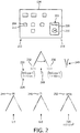
FIG. 2 is a conceptual and schematic diagram exemplary of user controls and irradiation levels, in accordance with the present invention; -
FIGs. 3A, 3B, 3C, and 3D are conceptual and schematic diagrams of possible screens and possible body tissue regions, in accordance with the present invention; and -
FIG. 4 consists of flow diagrams serving as examples of how the therapy specific ultrasound shear-wave-elastography exposure-safety facility operates. -
FIG. 1 depicts, by way of illustrative and non-limitative example, anultrasound scanner 100 which incorporates a therapy specific ultrasound shear-wave-elastography exposure-safety facility. In effect, the facility is implementable on a conventional diagnostic ultrasound system. Thescanner 100 includes anultrasound imaging probe 102 that incorporates anultrasound transducer 104, anultrasound beamformer 108, an ultrasoundexposure safety processor 112, and auser interface 116. Theuser interface 116 includes a display 118 having ascreen 120, and auser control section 124 that includes afacility enablement switch 128 and afingerprint scanner 132. - The
transducer 104 is configured for conventional ultrasound imaging modes, e.g., A-mode, two-dimensional (or "B-mode") imaging, Doppler, contrast imaging and etc. It is further configured for producing, i.e., forming and emitting, acoustic-radiation-force-basedpush pulses 136 for shear wave elastography imaging. Alternatively, separate transducers may be provided. For example, one can be designed for generating thepush pulses 136 withfoci 138. The other can be designed for generating tracking pulses along multiple beam directions, and for the B-mode imaging. The two types of transducer may be concentically arranged. Adot 139 appears as a broken line inFIG. 1 , and, as discussed further herein below, corresponds to an onscreen displayed symbol representative of the site of thefocus 138. - Activation of the facility may be accomplished via the
fingerprint scanner 132, as a safety measure. Alternatively, or in addition, it may be required that a password be entered. - The
facility enablement switch 128, and its arrangement in theuser control section 124, constitute an additional safety measure. - Referring to
FIG. 2 which constitutes an example scenario, theuser control section 124 includes multiple user-actuatable buttons. Theuser control section 124 may be a system touch panel, keyboard, or part of thedisplay screen 120. The buttons may be mechanical buttons or soft buttons on thedisplay screen 120. More generally, they may be any types of user-actuatable switches or other controls. Two of the buttons are specialized for activating respective modes of operation that both involve producing ultrasound push pulses, as in shear wave elastography applications. One of the modes may by a typical diagnostic mode for shear wave elastography. The other mode, the "therapy mode", is specific to the exposure-safety facility. The twobuttons control section 124. Thediagnostic mode button 204 is colored green; whereas, thetherapy mode button 208 for the exposure-safety facility is colored red. Also, thetherapy mode button 208 has alabel 209,icon 210 such as a cartoon, or both, representative of therapy. A cartoon, for example, may show the the multiple tips of an RFA electrode. By contrast, thediagnostic mode button 204 has no such label or icon. In the current example, the diagnostic mode button is provided with avisible label 211 representative of diagnostic imaging, such as "diagnosis." Thetherapy mode button 208 is, in addition, considerably larger than thediagnostic mode button 204. Due to the above-described design of the twobuttons therapy mode button 208 were to be pressed in error, the operator would then be prompted for password or biometric activation of the exposure-safety facility. - In therapy mode for the example scenario of
FIG. 2 , pushpulses 136 emitted to a region being treated are produced with an acoustic power that slightly exceeds FDA exposure limits for diagnostic ultrasound imaging. The larger acoustic power results in larger body tissue displacements and consequently greater SNR. Advantageously, what allows for this slight departure from FDA diagnostic safety standards is the fact that thepush pulse 136 is placed at a site of thermal ablation, and any possible bioeffects of the push pulse, mainly thermal, would not negatively impact that site. - Acoustic power varies with a number of factors, such as pulse duration, transmit voltage and aperture size. Acoustic power can be assessed as an average
acoustic power 220 over apredetermined time period 224, less than 100 milliseconds for example.Acoustic power 220 beyond a predetermined power threshold 228 for apush pulse 136 is only enabled in therapy mode, and only if thefocus 138 of the pulse in within the extended dead-tissue zone. The latter is a zone within the body tissue that includes a dead-tissue zone, such as an ablation zone, and a surrounding margin that can be planned and defined by the physician. The margin, which is at least partially surrounding, serves as a transition between normal, untreated tissue and the ablation zone. Anacoustic power 232 of X milliwatts (mW), which is equal to or below the threshold 228, might not, and at least typically would not, be used in therapy mode in the extended dead-tissue zone; whereas, anacoustic power 236 of Y mW which exceeds the threshold can only be produced in therapy mode and only if thefocus 138 of thepulse 136 is in the extended dead-tissue zone. More particularly, by default, if not always, therapymode push pulses 136 whosefoci 138 are in the extended dead-tissue zone are produced with an acoustic power that exceeds the threshold 228.Pulse 240 produced with acoustic power Y is, by virtue of the fact that Y exceeds the threshold 228, produced with at least one of a mechanical index (MI) 244, a thermal index (TI) 248, and a spatial-peak-temporal-average intensity (ISPTA) 252 exceeding respectively 1.9, 6.0 and 720 milliwatts per square centimeter. Althoughpulses 136 can be produced with two levels of acoustic power, they can alternatively be produced with multiple levels. For example, the relatively high-powered pulse 240 may be produced with one level of acoustic power when focused in the dead-tissue zone and with another, possibly lower, level when focused in the margin, albeit at a level that still exceeds the power threshold 228. -
FIG. 3A shows a dead-tissue zone 304 in which ablation occurs, surrounded by amargin 308. Thezone 304 and itsmargin 308 collectively are referred to as an "extended dead-tissue zone" 312. The latter exists withinbody tissue 316 underskin 320 of a human or animal patient or within an ex vivo sample. The dead-tissue zone 304 may correspond to, or include, a tumor treated by ablation, such as RFA, HIFU and microwave ablation. - Like the two
zones foci 138 of therapymode push pulses 136 are located; although, it is noted that a push pulse may be partially, or even totally albeit slightly, outside the imaging zone, and depicted as such by the placement of its corresponding symbol onscreen.. In particular, an imaging zone exists, like thefoci 138, within body tissue. Some of thefoci 138 are outside the extended dead-tissue zone 312, so that stiffness readings from inside the zone can be compared to those from outside so as to localize a current border of the zone. The border between themargin 308 and the dead-tissue zone 304 is also monitored. - Although ablation, in the examples discussed herein, is the cause of death of the tissue in the dead-
tissue zone 304, the intended scope of what is discussed herein is not limited to ablation. The cause of death may, for instance, be natural. In some of such cases, the slightly elevated power level of ultrasound exposure would not have any negative impact. In this scenario, elastography, shear wave or otherwise, may be performed for purposes other than determining borders. Such purposes may include staging, or fibrosis quantification, before surgery. - At least both the extended dead-
tissue zone 312 and the imaging zone are depicted on thescreen 120 of the display 118. A few examples reflecting particular user interactions are seen inFIGs. 3B, 3C, and 3D . B-mode images are shown, adhering to the convention that the fan-out narrows toward the top of the depiction, leading toward where theimaging probe 102 is located. - In
Figure 3B , over a B-mode image 328, adefinition 332 of the extended dead-tissue zone 312 is shown. Anelastography imaging box 336 has aspan 338 which is matched against a criterion in launching thepush pulses 136 and intervening body-tissue displacement tracking, as discussed further below. Theimaging box 336, a screen graphic, corresponds to animaging zone 324 which exists within body tissue. In the current example, it can be seen that theimaging zone 324 is disjoint from or non-overlapping 340 with the extended dead-tissue zone 312. Accordingly, no relativelyhigh power pulse 136 such as the above-mentionedpulse 240 issues. Thus, the threepulse focus sites imaging zone 324 and are, as ordinarily would be this case, not in the extended dead-tissue zone 312. The three sites 344-352 are accordingly green, indicating that therespective pulses 136 are produced with a lower, diagnostic-mode type ofacoustic power 232 such as that decided upon for apulse 136 whosefocus 138 is not within the extended dead-tissue zone 312. The three pulse focus sites 344-352 are depicted onscreen, overlaid onto the B-mode image 328, assymbols - For a second B-
mode image 368 seen inFIG. 3C , the twozones overlap 370 The threedots tissue zone 312, implying that the respective pulse sites correspond topulses 136 whosefoci 138 are within the extended dead-tissue zone. - For a third B-
mode image 384 as shown inFIG. 3D , the twozones imaging zone 324 overextends the extended dead-tissue zone 312 to form anon-overlapping portion 386. Four of thedots dots elastography imaging zone 324 can be extended to match any targeted extent of the B-mode image 384 underlying the superimposed graphics such as theimaging box 336. InFigs. 3A-3D , the number ofpush foci 138 is selected just for illustration purposes. The actual number ofpush foci 138 in the lateral and axial directions is intelligently determined by the system depending on information of the push pulse acoustic characteritcs, underlying tissue properties and the size of theelastography imaging box 336. "Axial" is in the imaging depth direction of theultrasound probe 102. "Lateral" is in the azimuthal direction. As discussed in more detail below, whenever dots 387-394 are seen onscreen and theimaging box 336 meets a sufficient-size criterion, body tissue displacement tracking is ongoing for the respective sites. The tracking can be serial, site by site, or in parallel, as via multiline acquisition. The tracking entails, for eachsite 344, firing tracking pulses repeatedly, at a pulse repetition frequency (PRF) such as 2 kilohertz (kHz). - Operationally and as seen in
FIG. 4 , in adiagnostic mode subprocedure 410, thegreen button 204 is pressed (step S402). A mode leading to push pulse operation is thereby enabled (step S404). Any firing of apush pulse 136 is with its acoustic power not exceeding the power threshold 228. - When, in a
main subprocedure 420, thered button 208 is pressed (step S412), the user is prompted to enter a password or input a biometric identifier, as by swiping a finger over a fingerprint scanner (step S414). If the password/identifier is not accepted (step S416), the user is re-prompted (step S418) and return is made to step S414. The extended dead-tissue zone 312 is spatially defined (step S420). Thedefinition 332 can be done either manually by the physician based on tumor appearance on real-time ultrasound imaging, or automatically by tumor segmentation through registering pre-surgery images captured by MRI, CT or other imaging modalities and real-time ultrasound images. In the first case, the system user interface will provide a simple tool to define shapes such as circle, ellipse, rectangle, square, and free-form polygons. Next, the ultrasoundexposure safety processor 112 sets a box-span threshold TBS, based on the size or an extent of the just-defined extended dead-tissue zone 312 (step S422). The larger thezone 312, the larger thespan 338 of theimaging box 336 will tend to be. Launching and maintaining body-tissue displacement tracking is dependent of thespan 338 being sufficiently large. The just-defined extended dead-tissue zone 312 is displayed on the screen 120 (step S424). At this point in the processing, asite visualizing subprocedure 430 and adisplacement tracking subprocedure 440 are launched for concurrent execution with the next, i.e., imaging box manipulation, step of theinstant subprocedure 420, with the displacement tracking subprocedure being "placed in a holding pattern" until the user sufficiently enlarges theimaging box 336. Next in themain subprocedure 420, theuser control section 124 is utilized to manipulate (e.g., drag, expand, contract) theimaging box 336 based on location and size of the tumor in the B-mode image 328 and on what location is to be currently imaged by the tracking (step S426). Thepulses 136 of a series may be focused on aparticular site 344, or on a group 344-352 of sites, and may be repetitive over that group. Anypush pulse site 344 added for the series by the manipulation of theimaging box 336 dynamically produces the pulses of the added site as part of the series. When it is detected, from theuser control section 124, that the manipulation has ended (step S428) but has later resumed (step S430), return is made to the box manipulation step S426). - Concurrently with step S426 of the
main subprocedure 420, thesite visualizing subprocedure 430 visualizes thepulse sites 344. First, the ultrasoundexposure safety processor 112 spatially relates thespatial definition 332 of the extended dead-tissue zone 312 to the spatial definition of the imaging zone 324 (step S432). The user may have provided the latter definition by the positions, and orientations, of the polygonal sides of theimaging box 336 or, in the case of a curved boundary, its position and, if applicable, orientation. With regard to the relating of the definitions and by way of example, if there is nooverlap 370 between theimaging zone 324 and the extended dead-tissue zone 312 (step S434), then, extending adjacently to, rather than toward or away from, the extended dead-tissue zone 312, there is formed a single linear array offoci 138 to be produced with acoustic power not exceeding the power threshold 228, as seen herein above for the three pulse focus sites 344-352 (step S436). Otherwise, if there is overlap 370 (step S434), the processing choice depends on whether theimaging box 336 is fully within the extended dead-tissue zone 312 (step S438). If theimaging box 336 is fully within the extended dead-tissue zone 312 (step S438), then, within the extended dead-tissue zone 312, there is formed a single linear array offoci 138 to be produced withacoustic power 236 that exceeds the power threshold 228 (step S440). If, on the other hand, theimaging box 336 is not fully within the extended dead-tissue zone 312 (step S438), the processing choice depends on whether the extended dead-tissue zone 312 is fully within the imaging box 336 (step S442). If the extended dead-tissue zone 312 is fully within the imaging box 336 (step S442), then, within theimaging box 336, a planar array offoci 138 in the axial and lateral directions is formed (step S444). Push pulses withfoci 138 in the extended dead-tissue zone 312 are to be produced withacoustic power 236 that exceeds the power threshold 228. Pushpulses 136 withfoci 138 not in the extended dead-tissue zone 312 are to be produced withacoustic power 232 that does not exceed the power threshold 228. An amount, or amounts, by which theimaging box 336 overextends the extended dead-tissue zone 312 can be taken into account. The automatic push pulse setting can, for example, create one or more push pulses outside the extended dead-tissue zone 312 in correspondence with the determined amount, or amounts, of overextension. On the other hand, if the extended dead-tissue zone 312 is not fully within the imaging box 336 (step S442), other relation-based rules are applicable (step S446). For example, a partial overlap implies higher-powered pulses in the overlap portion and lower-powered pulses in the remaining imaging box portion. This approach could be potentially used iteratively in ablating the entire tumor. In any event, regardless of the relation, symbols at thesites 344 of therespective foci 138 are displayed onscreen, e.g., as green or red dots 387-394 correspondingly (step S448). If imaging is complete (step S450), the subprocedure halts. Otherwise, if the adjusting is still being made (step S450), return is made to step S432. - Also concurrently with step S426 of subprocedure main 420, the
displacement tracking subprocedure 440 checks for when the box-span threshold TBS is met (step S452). Upon being met (step S452), anablation monitoring subprocedure 450 is launched, and, in thecurrent subprocedure 440, each of a series ofpush pulses 136 is produced (step S454). Thepulses 136 of the series may be focused on aparticular site 344, or on a group of sites, and may be repetitive over that group. Eachpush pulse 136 generates a respective shear wave originating from the site of the pulse (step S456). The consequent body tissue displacement, for eachpush pulse 136, is tracked by lateral location, and the tracking results are stored (step S458). If tracking is to continue (step S460), return is made to the threshold checking step S452. -
Subprocedure 450 updates a stiffness map and, based on the map, distinguisheszones - These borders can be visually monitored by the physician in controlling, or stopping, the ablation procedure, thereby enabling sufficient ablation without excess damage to
body tissue 316. Lines representing the borders can be graphically depicted onscreen, or the borders can be surmised by the physician based on a displayed, dynamically-updated color-coded rendition of the stiffness values in the map. - An ultrasound exposure safety processor is configured for spatially relating respective definitions of an imaging zone, and an extended dead-tissue zone that includes both a dead-tissue zone and a surrounding margin. Based on whether a push pulse focus is to be within the extended dead-tissue zone, the processor automatically decides as to a level of acoustic power with which the pulse is to be produced. If the pulse focus is to be within the extended dead-tissue zone, the pulse may be produced with an MI, a TI, and/or an ISPTA that exceeds respectively 1.9, 6.0 and 720 milliwatts per square centimeter. The imaging zone may be definable interactively so as to dynamically trigger the deciding and the producing, with optimal push pulse settings being dynamically derived automatically, without the need for user intervention. A display of multiple push pulse sites allows user manipulation of spatial definition indicia to dynamically control displacement tracking.
- The proposed methodology can advantageously be applied clinically in cardiac and non-cardiac treatment or examination. Clinical application can be made to examination or monitoring of bodily tissue such as the liver, prostate, and myocardium, where local tissue stiffness will be elevated by therapy treatment, such as heat based RF ablation, HIFU and microwave ablation, or for staging a tumor pre-surgery.
- While the invention has been illustrated and described in detail in the drawings and foregoing description, such illustration and description are to be considered illustrative or exemplary and not restrictive; the invention is not limited to the disclosed embodiments. The invention is defined in the appended claims.
- For example, the shear stiffness map may be displayed as an overlay on the B-mode image supplemented with push pulse sites, or may be displayed separately, alongside, overlaying a separate B-mode image. As another example, the visualization of extended dead-tissue zone, the imaging zone, pulse site symbols, and ultrasound image may be implemented as three-dimensional.
- Other variations to the disclosed embodiments can be understood and effected by those skilled in the art in practicing the claimed invention, from a study of the drawings, the disclosure, and the appended claims. In the claims, the word "comprising" does not exclude other elements or steps, and the indefinite article "a" or "an" does not exclude a plurality. Any reference signs in the claims should not be construed as limiting the scope.
- A computer program can be stored momentarily, temporarily or for a longer period of time on a suitable computer-readable medium, such as an optical storage medium or a solid-state medium. Such a medium is non-transitory only in the sense of not being a transitory, propagating signal, but includes other forms of computer-readable media such as register memory, processor cache and RAM
- A single processor or other unit may fulfill the functions of several items recited in the claims. The mere fact that certain measures are recited in mutually different dependent claims does not indicate that a combination of these measures cannot be used to advantage.
Claims (15)
- A medical ultrasound apparatus (100), comprising an ultrasound exposure safety processor (112) configured for:spatially relating (S432) respective definitions of: a) an extended dead-tissue zone (312) that includes both a dead-tissue zone (304) of tissue to be ablated and a surrounding margin (308); and b) an imaging zone (324);based on whether a focus (138) of a push pulse (136) is to be within said extended dead-tissue zone, automatically deciding (S434, S438, S442) as to a level of acoustic power (232, 236) with which said pulse is to be produced; andcausing (S436, S440, S444, S446) said pulse to be produced with the decided upon level of acoustic power.
- The apparatus of claim 1, further comprising a user interface (116) for the defining (S424) of said imaging zone (324) interactively, said defining preferably comprising resizing (S426) an imaging box (336) sufficiently to achieve a predetermined span, said apparatus being configured for dynamically triggering said deciding responsive to said defining of said imaging zone.
- The apparatus of claim 1, said processor being configured for automatically determining optimal push pulse settings based on the relation.
- The apparatus of claim 3, said settings being for forming a shear stiffness map based on a shear wave generated by said pulse (136).
- The apparatus of claim 3, said determining comprising taking into account an amount of coverage, if any, by said imaging zone (324) over said extended dead-tissue zone (312).
- The apparatus of claim 1, the causing being dynamically responsive to the defining of said imaging zone (324).
- The apparatus of claim 1, said pulse being one of a series of push pulses (136) said processor causes to being produced with a respective decided upon level of acoustic power (232, 236), said apparatus further comprising a display (118), said apparatus being configured for, via said display, spatially depicting concurrently (S448) two types of push pulses, in an instance in which said series of said pulses includes, as one of the types, at least one push pulse whose focus is in said extended dead-tissue zone (312) and, as the other type, at least one other push pulse whose focus is outside said extended dead-tissue zone, said display respectively indicating push pulse by push pulse, via their individual depictions, the type of the push pulse.
- The apparatus of claim 1, said pulse being one of a series of push pulses (136) said processor causes to being produced with a respective decided upon level of acoustic power (232, 236), said apparatus further comprising a user interface (116) and being configured for visualizing, on said user interface, sites (344-352) corresponding to the foci, said visualizing being dynamically responsive to said deciding.
- The apparatus of claim 8, said visualizing comprising depicting symbols (356-364, 372-380, 387-394) correspondingly for said sites, the apparatus being preferably further configured for depicting, via said user interface, spatial indicia of the two definitions (S426, S448) concurrently with said symbols.
- The apparatus of claim 1, further comprising a user interface and being configured for visual outlining of said imaging zone, on said interface, via an imaging box.
- The apparatus of claim 10, said pulse being one of a series of push pulses (136) said processor causes to being produced with a respective decided upon level of acoustic power (232, 236), the apparatus being further configured for dynamically updating said deciding (S432) responsive to manipulation of said box (S426), and preferably for dynamically producing, as part of said series, any push pulse added to said series by said manipulation.
- The apparatus of claim 1, said margin (308) serving as a transition between non-treated, normal tissue and said dead-tissue zone (304), said apparatus being configured for, via shear wave elastography using said pulse, measuring stiffness of body tissue in said imaging zone (324) so as to monitor, in real time, for spatially distinguishing among said normal tissue, said margin and said dead-tissue zone.
- The apparatus of claim 1, further comprising a user interface (116) that includes a section (124) with manually-actuatable controls, said section having opposite ends (212, 216), said apparatus being configured such that:a) a first control (208) from among said controls is located at one of said ends, a second control (204) from among said controls is located at the other end; and/orb) the first (208) of said controls is colored red and has at least one of a label (209), or icon (210), correspondingly representative of therapy, and the second (204) of said controls is colored green and does not have such a label or icon;
said apparatus being further configured such that, in case said level exceeds a predetermined threshold (228), actuation of said first control (208) is required for activating the producing and such that actuation of said second control, although leading to an operational mode for push pulses, does not activate any producing at a level exceeding said threshold, and
wherein said processor (112) is preferably further configured for prompting (S414) the user to enter a password or input a biometric identifier when the first control (208) is actuated. - The apparatus of claim 1, said deciding occurring in a given mode of operation, said apparatus having another mode of operation (S404) for producing push pulses in which said apparatus is incapable of producing any push pulse with an acoustic power as high as said level is enabled for in case said focus is, in said given mode, within said extended dead-tissue zone.
- A computer readable medium embodying a computer program for ultrasound exposure safety, said program having instructions executable by a processor for performing a plurality of acts, among said plurality there being the acts of:spatially relating (S432) respective definitions of: a) an extended dead-tissue zone (312) that includes both a dead-tissue zone (304) of tissue to be ablated and a surrounding margin (308); and b) an imaging zone (324); andbased on whether a focus (138) of a push pulse (136) is to be within said extended dead-tissue zone, automatically deciding (S434, S438, S442) as to a level of acoustic power (232, 236) with which said pulse is to be produced.
Applications Claiming Priority (2)
| Application Number | Priority Date | Filing Date | Title |
|---|---|---|---|
| US201462019030P | 2014-06-30 | 2014-06-30 | |
| PCT/IB2015/054498 WO2016001783A1 (en) | 2014-06-30 | 2015-06-15 | Ultrasound shear wave elastography featuring therapy monitoring |
Publications (2)
| Publication Number | Publication Date |
|---|---|
| EP3160358A1 EP3160358A1 (en) | 2017-05-03 |
| EP3160358B1 true EP3160358B1 (en) | 2020-08-05 |
Family
ID=53758484
Family Applications (1)
| Application Number | Title | Priority Date | Filing Date |
|---|---|---|---|
| EP15742390.6A Active EP3160358B1 (en) | 2014-06-30 | 2015-06-15 | Ultrasound shear wave elastography featuring therapy monitoring |
Country Status (4)
| Country | Link |
|---|---|
| US (1) | US11191522B2 (en) |
| EP (1) | EP3160358B1 (en) |
| JP (1) | JP6517247B2 (en) |
| WO (1) | WO2016001783A1 (en) |
Families Citing this family (4)
| Publication number | Priority date | Publication date | Assignee | Title |
|---|---|---|---|---|
| US20180235576A1 (en) * | 2017-02-22 | 2018-08-23 | Covidien Lp | Ultrasound doppler and elastography for ablation prediction and monitoring |
| ES2687485B1 (en) * | 2017-03-24 | 2019-07-31 | Univ Granada | TRANSLUMINAL DEVICE AND PROCEDURE FOR THE MECHANICAL CHARACTERIZATION OF STRUCTURES |
| CN111698947A (en) * | 2018-02-09 | 2020-09-22 | 皇家飞利浦有限公司 | Multi-parameter tissue hardness quantification |
| CN112135567A (en) | 2018-05-03 | 2020-12-25 | 皇家飞利浦有限公司 | Shear wave amplitude reconstruction for tissue elasticity monitoring and display |
Family Cites Families (8)
| Publication number | Priority date | Publication date | Assignee | Title |
|---|---|---|---|---|
| US20050215899A1 (en) * | 2004-01-15 | 2005-09-29 | Trahey Gregg E | Methods, systems, and computer program products for acoustic radiation force impulse (ARFI) imaging of ablated tissue |
| US20100016719A1 (en) * | 2008-07-16 | 2010-01-21 | Siemens Medical Solutions Usa, Inc. | Adaptive regulation of acoustic output power in medical ultrasound imaging |
| JP2012045198A (en) * | 2010-08-27 | 2012-03-08 | Hitachi Medical Corp | Treatment support device, and treatment support system |
| US8961418B2 (en) * | 2010-10-06 | 2015-02-24 | Siemens Medical Solutions Usa, Inc. | Solving for shear wave information in medical ultrasound imaging |
| US8715187B2 (en) * | 2010-12-17 | 2014-05-06 | General Electric Company | Systems and methods for automatically identifying and segmenting different tissue types in ultrasound images |
| KR20120131552A (en) * | 2011-05-25 | 2012-12-05 | 삼성전자주식회사 | Method and system for diagnosis and treatment using ultrasound |
| JP6004255B2 (en) * | 2012-05-31 | 2016-10-05 | 国立大学法人 東京大学 | Ultrasound medical device |
| KR20140049137A (en) * | 2012-10-12 | 2014-04-25 | 삼성전자주식회사 | Medical image analyzing apparatus and method |
-
2015
- 2015-06-15 WO PCT/IB2015/054498 patent/WO2016001783A1/en active Application Filing
- 2015-06-15 EP EP15742390.6A patent/EP3160358B1/en active Active
- 2015-06-15 US US15/320,570 patent/US11191522B2/en active Active
- 2015-06-15 JP JP2016575408A patent/JP6517247B2/en active Active
Non-Patent Citations (1)
| Title |
|---|
| None * |
Also Published As
| Publication number | Publication date |
|---|---|
| US11191522B2 (en) | 2021-12-07 |
| US20170188997A1 (en) | 2017-07-06 |
| WO2016001783A1 (en) | 2016-01-07 |
| JP2017518843A (en) | 2017-07-13 |
| EP3160358A1 (en) | 2017-05-03 |
| JP6517247B2 (en) | 2019-05-22 |
Similar Documents
| Publication | Publication Date | Title |
|---|---|---|
| US11109840B2 (en) | Calibration of ultrasonic elasticity-based lesion-border mapping | |
| CN106963415B (en) | Ultrasound system and method for use in heat affected zones | |
| RU2540090C2 (en) | Image device | |
| JP6257997B2 (en) | Ultrasonic diagnostic apparatus and ultrasonic diagnostic apparatus control method | |
| JP6629031B2 (en) | Ultrasound diagnostic device and medical image diagnostic device | |
| WO2014077396A1 (en) | Ultrasound diagnostic device and image processing method | |
| US10524768B2 (en) | Medical image diagnostic apparatus and medical image processing apparatus | |
| EP3160358B1 (en) | Ultrasound shear wave elastography featuring therapy monitoring | |
| JP2013043082A (en) | Method and apparatus for monitoring temperature of treated area using ultrasound, and system for treatment and diagnosis by use of the ultrasound | |
| JP2008155022A (en) | Method of increasing visibility of ablation range | |
| US11298109B2 (en) | Ultrasonic diagnostic apparatus and image processing apparatus | |
| BR112015032724B1 (en) | ULTRASONIC ELASTOGRAPHY SYSTEM AND ULTRASONIC ELASTOGRAPHY METHOD TO INSPECT AN ANATOMICAL SITE | |
| CN105451663A (en) | Ultrasound acquisition feedback guidance to a target view | |
| JP5689591B2 (en) | Ultrasonic diagnostic apparatus and ultrasonic image processing program | |
| Xu et al. | Acoustic radiation force impulse elastography for efficacy evaluation after hepatocellular carcinoma radiofrequency ablation: a comparative study with contrast-enhanced ultrasound | |
| EP3366252B1 (en) | Ultrasound doppler and elastography for ablation prediction and monitoring | |
| JP5731267B2 (en) | Treatment support system and medical image processing apparatus | |
| JP6599885B2 (en) | A method for thermal fracture mark size control based on normalized displacement difference | |
| US11179140B2 (en) | Ablation treatment device sensor | |
| EP4182019A1 (en) | Ultrasound ablation apparatus and methods of use | |
| JP2017080040A (en) | Ultrasonic diagnostic equipment and program | |
| KR20140094955A (en) | Method and apparatus for generating a temperature image, and ultrasound system | |
| Dahl et al. | Acoustic radiation force imaging | |
| Xie et al. | Quantitative assessment of thermal lesion stiffness in the liver: Initial ex vivo results | |
| Shah | Optimizing the Diagnostic Information |
Legal Events
| Date | Code | Title | Description |
|---|---|---|---|
| STAA | Information on the status of an ep patent application or granted ep patent |
Free format text: STATUS: THE INTERNATIONAL PUBLICATION HAS BEEN MADE |
|
| PUAI | Public reference made under article 153(3) epc to a published international application that has entered the european phase |
Free format text: ORIGINAL CODE: 0009012 |
|
| STAA | Information on the status of an ep patent application or granted ep patent |
Free format text: STATUS: REQUEST FOR EXAMINATION WAS MADE |
|
| 17P | Request for examination filed |
Effective date: 20170130 |
|
| AK | Designated contracting states |
Kind code of ref document: A1 Designated state(s): AL AT BE BG CH CY CZ DE DK EE ES FI FR GB GR HR HU IE IS IT LI LT LU LV MC MK MT NL NO PL PT RO RS SE SI SK SM TR |
|
| AX | Request for extension of the european patent |
Extension state: BA ME |
|
| DAV | Request for validation of the european patent (deleted) | ||
| DAX | Request for extension of the european patent (deleted) | ||
| GRAP | Despatch of communication of intention to grant a patent |
Free format text: ORIGINAL CODE: EPIDOSNIGR1 |
|
| STAA | Information on the status of an ep patent application or granted ep patent |
Free format text: STATUS: GRANT OF PATENT IS INTENDED |
|
| RIC1 | Information provided on ipc code assigned before grant |
Ipc: A61B 8/08 20060101AFI20200129BHEP Ipc: A61B 18/14 20060101ALI20200129BHEP |
|
| RAP1 | Party data changed (applicant data changed or rights of an application transferred) |
Owner name: KONINKLIJKE PHILIPS N.V. |
|
| INTG | Intention to grant announced |
Effective date: 20200224 |
|
| RIN1 | Information on inventor provided before grant (corrected) |
Inventor name: HUANG, SHENG-WEN Inventor name: XIE, HUA Inventor name: ZHOU, SHIWEI Inventor name: SHAMDASANI, VIJAY THAKUR Inventor name: ROBERT, JEAN-LUC |
|
| GRAS | Grant fee paid |
Free format text: ORIGINAL CODE: EPIDOSNIGR3 |
|
| GRAA | (expected) grant |
Free format text: ORIGINAL CODE: 0009210 |
|
| STAA | Information on the status of an ep patent application or granted ep patent |
Free format text: STATUS: THE PATENT HAS BEEN GRANTED |
|
| AK | Designated contracting states |
Kind code of ref document: B1 Designated state(s): AL AT BE BG CH CY CZ DE DK EE ES FI FR GB GR HR HU IE IS IT LI LT LU LV MC MK MT NL NO PL PT RO RS SE SI SK SM TR |
|
| REG | Reference to a national code |
Ref country code: GB Ref legal event code: FG4D |
|
| REG | Reference to a national code |
Ref country code: CH Ref legal event code: EP |
|
| REG | Reference to a national code |
Ref country code: AT Ref legal event code: REF Ref document number: 1297588 Country of ref document: AT Kind code of ref document: T Effective date: 20200815 |
|
| REG | Reference to a national code |
Ref country code: DE Ref legal event code: R096 Ref document number: 602015056936 Country of ref document: DE |
|
| REG | Reference to a national code |
Ref country code: IE Ref legal event code: FG4D |
|
| REG | Reference to a national code |
Ref country code: DE Ref legal event code: R084 Ref document number: 602015056936 Country of ref document: DE |
|
| REG | Reference to a national code |
Ref country code: LT Ref legal event code: MG4D |
|
| REG | Reference to a national code |
Ref country code: GB Ref legal event code: 746 Effective date: 20201208 |
|
| REG | Reference to a national code |
Ref country code: NL Ref legal event code: MP Effective date: 20200805 |
|
| REG | Reference to a national code |
Ref country code: AT Ref legal event code: MK05 Ref document number: 1297588 Country of ref document: AT Kind code of ref document: T Effective date: 20200805 |
|
| PG25 | Lapsed in a contracting state [announced via postgrant information from national office to epo] |
Ref country code: FI Free format text: LAPSE BECAUSE OF FAILURE TO SUBMIT A TRANSLATION OF THE DESCRIPTION OR TO PAY THE FEE WITHIN THE PRESCRIBED TIME-LIMIT Effective date: 20200805 Ref country code: NO Free format text: LAPSE BECAUSE OF FAILURE TO SUBMIT A TRANSLATION OF THE DESCRIPTION OR TO PAY THE FEE WITHIN THE PRESCRIBED TIME-LIMIT Effective date: 20201105 Ref country code: GR Free format text: LAPSE BECAUSE OF FAILURE TO SUBMIT A TRANSLATION OF THE DESCRIPTION OR TO PAY THE FEE WITHIN THE PRESCRIBED TIME-LIMIT Effective date: 20201106 Ref country code: SE Free format text: LAPSE BECAUSE OF FAILURE TO SUBMIT A TRANSLATION OF THE DESCRIPTION OR TO PAY THE FEE WITHIN THE PRESCRIBED TIME-LIMIT Effective date: 20200805 Ref country code: BG Free format text: LAPSE BECAUSE OF FAILURE TO SUBMIT A TRANSLATION OF THE DESCRIPTION OR TO PAY THE FEE WITHIN THE PRESCRIBED TIME-LIMIT Effective date: 20201105 Ref country code: PT Free format text: LAPSE BECAUSE OF FAILURE TO SUBMIT A TRANSLATION OF THE DESCRIPTION OR TO PAY THE FEE WITHIN THE PRESCRIBED TIME-LIMIT Effective date: 20201207 Ref country code: HR Free format text: LAPSE BECAUSE OF FAILURE TO SUBMIT A TRANSLATION OF THE DESCRIPTION OR TO PAY THE FEE WITHIN THE PRESCRIBED TIME-LIMIT Effective date: 20200805 Ref country code: AT Free format text: LAPSE BECAUSE OF FAILURE TO SUBMIT A TRANSLATION OF THE DESCRIPTION OR TO PAY THE FEE WITHIN THE PRESCRIBED TIME-LIMIT Effective date: 20200805 Ref country code: LT Free format text: LAPSE BECAUSE OF FAILURE TO SUBMIT A TRANSLATION OF THE DESCRIPTION OR TO PAY THE FEE WITHIN THE PRESCRIBED TIME-LIMIT Effective date: 20200805 Ref country code: ES Free format text: LAPSE BECAUSE OF FAILURE TO SUBMIT A TRANSLATION OF THE DESCRIPTION OR TO PAY THE FEE WITHIN THE PRESCRIBED TIME-LIMIT Effective date: 20200805 |
|
| PG25 | Lapsed in a contracting state [announced via postgrant information from national office to epo] |
Ref country code: PL Free format text: LAPSE BECAUSE OF FAILURE TO SUBMIT A TRANSLATION OF THE DESCRIPTION OR TO PAY THE FEE WITHIN THE PRESCRIBED TIME-LIMIT Effective date: 20200805 Ref country code: NL Free format text: LAPSE BECAUSE OF FAILURE TO SUBMIT A TRANSLATION OF THE DESCRIPTION OR TO PAY THE FEE WITHIN THE PRESCRIBED TIME-LIMIT Effective date: 20200805 Ref country code: LV Free format text: LAPSE BECAUSE OF FAILURE TO SUBMIT A TRANSLATION OF THE DESCRIPTION OR TO PAY THE FEE WITHIN THE PRESCRIBED TIME-LIMIT Effective date: 20200805 Ref country code: RS Free format text: LAPSE BECAUSE OF FAILURE TO SUBMIT A TRANSLATION OF THE DESCRIPTION OR TO PAY THE FEE WITHIN THE PRESCRIBED TIME-LIMIT Effective date: 20200805 Ref country code: IS Free format text: LAPSE BECAUSE OF FAILURE TO SUBMIT A TRANSLATION OF THE DESCRIPTION OR TO PAY THE FEE WITHIN THE PRESCRIBED TIME-LIMIT Effective date: 20201205 |
|
| PG25 | Lapsed in a contracting state [announced via postgrant information from national office to epo] |
Ref country code: EE Free format text: LAPSE BECAUSE OF FAILURE TO SUBMIT A TRANSLATION OF THE DESCRIPTION OR TO PAY THE FEE WITHIN THE PRESCRIBED TIME-LIMIT Effective date: 20200805 Ref country code: RO Free format text: LAPSE BECAUSE OF FAILURE TO SUBMIT A TRANSLATION OF THE DESCRIPTION OR TO PAY THE FEE WITHIN THE PRESCRIBED TIME-LIMIT Effective date: 20200805 Ref country code: SM Free format text: LAPSE BECAUSE OF FAILURE TO SUBMIT A TRANSLATION OF THE DESCRIPTION OR TO PAY THE FEE WITHIN THE PRESCRIBED TIME-LIMIT Effective date: 20200805 Ref country code: DK Free format text: LAPSE BECAUSE OF FAILURE TO SUBMIT A TRANSLATION OF THE DESCRIPTION OR TO PAY THE FEE WITHIN THE PRESCRIBED TIME-LIMIT Effective date: 20200805 Ref country code: CZ Free format text: LAPSE BECAUSE OF FAILURE TO SUBMIT A TRANSLATION OF THE DESCRIPTION OR TO PAY THE FEE WITHIN THE PRESCRIBED TIME-LIMIT Effective date: 20200805 |
|
| REG | Reference to a national code |
Ref country code: DE Ref legal event code: R097 Ref document number: 602015056936 Country of ref document: DE |
|
| PG25 | Lapsed in a contracting state [announced via postgrant information from national office to epo] |
Ref country code: AL Free format text: LAPSE BECAUSE OF FAILURE TO SUBMIT A TRANSLATION OF THE DESCRIPTION OR TO PAY THE FEE WITHIN THE PRESCRIBED TIME-LIMIT Effective date: 20200805 |
|
| PLBE | No opposition filed within time limit |
Free format text: ORIGINAL CODE: 0009261 |
|
| STAA | Information on the status of an ep patent application or granted ep patent |
Free format text: STATUS: NO OPPOSITION FILED WITHIN TIME LIMIT |
|
| PG25 | Lapsed in a contracting state [announced via postgrant information from national office to epo] |
Ref country code: SK Free format text: LAPSE BECAUSE OF FAILURE TO SUBMIT A TRANSLATION OF THE DESCRIPTION OR TO PAY THE FEE WITHIN THE PRESCRIBED TIME-LIMIT Effective date: 20200805 |
|
| 26N | No opposition filed |
Effective date: 20210507 |
|
| PG25 | Lapsed in a contracting state [announced via postgrant information from national office to epo] |
Ref country code: IT Free format text: LAPSE BECAUSE OF FAILURE TO SUBMIT A TRANSLATION OF THE DESCRIPTION OR TO PAY THE FEE WITHIN THE PRESCRIBED TIME-LIMIT Effective date: 20200805 |
|
| PG25 | Lapsed in a contracting state [announced via postgrant information from national office to epo] |
Ref country code: SI Free format text: LAPSE BECAUSE OF FAILURE TO SUBMIT A TRANSLATION OF THE DESCRIPTION OR TO PAY THE FEE WITHIN THE PRESCRIBED TIME-LIMIT Effective date: 20200805 |
|
| PG25 | Lapsed in a contracting state [announced via postgrant information from national office to epo] |
Ref country code: MC Free format text: LAPSE BECAUSE OF FAILURE TO SUBMIT A TRANSLATION OF THE DESCRIPTION OR TO PAY THE FEE WITHIN THE PRESCRIBED TIME-LIMIT Effective date: 20200805 |
|
| REG | Reference to a national code |
Ref country code: CH Ref legal event code: PL |
|
| REG | Reference to a national code |
Ref country code: BE Ref legal event code: MM Effective date: 20210630 |
|
| PG25 | Lapsed in a contracting state [announced via postgrant information from national office to epo] |
Ref country code: LU Free format text: LAPSE BECAUSE OF NON-PAYMENT OF DUE FEES Effective date: 20210615 |
|
| PG25 | Lapsed in a contracting state [announced via postgrant information from national office to epo] |
Ref country code: LI Free format text: LAPSE BECAUSE OF NON-PAYMENT OF DUE FEES Effective date: 20210630 Ref country code: IE Free format text: LAPSE BECAUSE OF NON-PAYMENT OF DUE FEES Effective date: 20210615 Ref country code: CH Free format text: LAPSE BECAUSE OF NON-PAYMENT OF DUE FEES Effective date: 20210630 |
|
| PG25 | Lapsed in a contracting state [announced via postgrant information from national office to epo] |
Ref country code: BE Free format text: LAPSE BECAUSE OF NON-PAYMENT OF DUE FEES Effective date: 20210630 |
|
| PG25 | Lapsed in a contracting state [announced via postgrant information from national office to epo] |
Ref country code: HU Free format text: LAPSE BECAUSE OF FAILURE TO SUBMIT A TRANSLATION OF THE DESCRIPTION OR TO PAY THE FEE WITHIN THE PRESCRIBED TIME-LIMIT; INVALID AB INITIO Effective date: 20150615 |
|
| PG25 | Lapsed in a contracting state [announced via postgrant information from national office to epo] |
Ref country code: CY Free format text: LAPSE BECAUSE OF FAILURE TO SUBMIT A TRANSLATION OF THE DESCRIPTION OR TO PAY THE FEE WITHIN THE PRESCRIBED TIME-LIMIT Effective date: 20200805 |
|
| PGFP | Annual fee paid to national office [announced via postgrant information from national office to epo] |
Ref country code: FR Payment date: 20230622 Year of fee payment: 9 Ref country code: DE Payment date: 20230627 Year of fee payment: 9 |
|
| PGFP | Annual fee paid to national office [announced via postgrant information from national office to epo] |
Ref country code: GB Payment date: 20230620 Year of fee payment: 9 |
|
| PG25 | Lapsed in a contracting state [announced via postgrant information from national office to epo] |
Ref country code: MK Free format text: LAPSE BECAUSE OF FAILURE TO SUBMIT A TRANSLATION OF THE DESCRIPTION OR TO PAY THE FEE WITHIN THE PRESCRIBED TIME-LIMIT Effective date: 20200805 |