EP3748896B1 - Design of search spaces and grants in emtc - Google Patents
Design of search spaces and grants in emtc Download PDFInfo
- Publication number
- EP3748896B1 EP3748896B1 EP20187966.5A EP20187966A EP3748896B1 EP 3748896 B1 EP3748896 B1 EP 3748896B1 EP 20187966 A EP20187966 A EP 20187966A EP 3748896 B1 EP3748896 B1 EP 3748896B1
- Authority
- EP
- European Patent Office
- Prior art keywords
- search space
- frequency band
- control information
- processor
- css
- Prior art date
- Legal status (The legal status is an assumption and is not a legal conclusion. Google has not performed a legal analysis and makes no representation as to the accuracy of the status listed.)
- Active
Links
- 238000013461 design Methods 0.000 title description 8
- 230000005540 biological transmission Effects 0.000 claims description 149
- 238000004891 communication Methods 0.000 claims description 87
- 238000000034 method Methods 0.000 claims description 78
- 238000012544 monitoring process Methods 0.000 claims description 47
- 238000010586 diagram Methods 0.000 description 23
- 230000008569 process Effects 0.000 description 16
- 208000037918 transfusion-transmitted disease Diseases 0.000 description 12
- 238000005516 engineering process Methods 0.000 description 10
- 230000015654 memory Effects 0.000 description 10
- 238000001228 spectrum Methods 0.000 description 10
- 239000011159 matrix material Substances 0.000 description 6
- 230000002776 aggregation Effects 0.000 description 5
- 238000004220 aggregation Methods 0.000 description 5
- 239000000969 carrier Substances 0.000 description 5
- 230000006870 function Effects 0.000 description 5
- 238000012545 processing Methods 0.000 description 5
- 208000032370 Secondary transmission Diseases 0.000 description 4
- 230000001419 dependent effect Effects 0.000 description 4
- 101000741965 Homo sapiens Inactive tyrosine-protein kinase PRAG1 Proteins 0.000 description 3
- 102100038659 Inactive tyrosine-protein kinase PRAG1 Human genes 0.000 description 3
- 230000003287 optical effect Effects 0.000 description 3
- 230000001276 controlling effect Effects 0.000 description 2
- 230000000875 corresponding effect Effects 0.000 description 2
- 239000000835 fiber Substances 0.000 description 2
- 230000003993 interaction Effects 0.000 description 2
- 230000007774 longterm Effects 0.000 description 2
- 238000005259 measurement Methods 0.000 description 2
- 238000012986 modification Methods 0.000 description 2
- 230000004048 modification Effects 0.000 description 2
- 230000008520 organization Effects 0.000 description 2
- 239000002245 particle Substances 0.000 description 2
- 230000004044 response Effects 0.000 description 2
- 230000011664 signaling Effects 0.000 description 2
- 230000001360 synchronised effect Effects 0.000 description 2
- 230000007704 transition Effects 0.000 description 2
- 101150071132 LTE1 gene Proteins 0.000 description 1
- 230000008901 benefit Effects 0.000 description 1
- 230000001413 cellular effect Effects 0.000 description 1
- 230000008859 change Effects 0.000 description 1
- 230000001427 coherent effect Effects 0.000 description 1
- 238000004590 computer program Methods 0.000 description 1
- 230000002596 correlated effect Effects 0.000 description 1
- 238000001514 detection method Methods 0.000 description 1
- KRTWHKZMWCZCIK-VRZYSOTLSA-N leukotriene E3 Chemical compound CCCCCCCC\C=C/C=C/C=C/[C@@H](SC[C@H](N)C(O)=O)[C@@H](O)CCCC(O)=O KRTWHKZMWCZCIK-VRZYSOTLSA-N 0.000 description 1
- 239000000463 material Substances 0.000 description 1
- 238000010295 mobile communication Methods 0.000 description 1
- 238000005192 partition Methods 0.000 description 1
- 230000001105 regulatory effect Effects 0.000 description 1
- 238000012827 research and development Methods 0.000 description 1
- 238000012549 training Methods 0.000 description 1
- 238000012546 transfer Methods 0.000 description 1
Images


Classifications
-
- H—ELECTRICITY
- H04—ELECTRIC COMMUNICATION TECHNIQUE
- H04L—TRANSMISSION OF DIGITAL INFORMATION, e.g. TELEGRAPHIC COMMUNICATION
- H04L5/00—Arrangements affording multiple use of the transmission path
- H04L5/003—Arrangements for allocating sub-channels of the transmission path
- H04L5/0053—Allocation of signaling, i.e. of overhead other than pilot signals
-
- H—ELECTRICITY
- H04—ELECTRIC COMMUNICATION TECHNIQUE
- H04W—WIRELESS COMMUNICATION NETWORKS
- H04W4/00—Services specially adapted for wireless communication networks; Facilities therefor
- H04W4/70—Services for machine-to-machine communication [M2M] or machine type communication [MTC]
-
- H—ELECTRICITY
- H04—ELECTRIC COMMUNICATION TECHNIQUE
- H04L—TRANSMISSION OF DIGITAL INFORMATION, e.g. TELEGRAPHIC COMMUNICATION
- H04L5/00—Arrangements affording multiple use of the transmission path
- H04L5/0001—Arrangements for dividing the transmission path
- H04L5/0003—Two-dimensional division
- H04L5/0005—Time-frequency
- H04L5/0007—Time-frequency the frequencies being orthogonal, e.g. OFDM(A), DMT
-
- H—ELECTRICITY
- H04—ELECTRIC COMMUNICATION TECHNIQUE
- H04B—TRANSMISSION
- H04B7/00—Radio transmission systems, i.e. using radiation field
- H04B7/02—Diversity systems; Multi-antenna system, i.e. transmission or reception using multiple antennas
- H04B7/04—Diversity systems; Multi-antenna system, i.e. transmission or reception using multiple antennas using two or more spaced independent antennas
- H04B7/0413—MIMO systems
-
- H—ELECTRICITY
- H04—ELECTRIC COMMUNICATION TECHNIQUE
- H04B—TRANSMISSION
- H04B7/00—Radio transmission systems, i.e. using radiation field
- H04B7/02—Diversity systems; Multi-antenna system, i.e. transmission or reception using multiple antennas
- H04B7/04—Diversity systems; Multi-antenna system, i.e. transmission or reception using multiple antennas using two or more spaced independent antennas
- H04B7/06—Diversity systems; Multi-antenna system, i.e. transmission or reception using multiple antennas using two or more spaced independent antennas at the transmitting station
- H04B7/0613—Diversity systems; Multi-antenna system, i.e. transmission or reception using multiple antennas using two or more spaced independent antennas at the transmitting station using simultaneous transmission
- H04B7/0615—Diversity systems; Multi-antenna system, i.e. transmission or reception using multiple antennas using two or more spaced independent antennas at the transmitting station using simultaneous transmission of weighted versions of same signal
- H04B7/0619—Diversity systems; Multi-antenna system, i.e. transmission or reception using multiple antennas using two or more spaced independent antennas at the transmitting station using simultaneous transmission of weighted versions of same signal using feedback from receiving side
-
- H—ELECTRICITY
- H04—ELECTRIC COMMUNICATION TECHNIQUE
- H04B—TRANSMISSION
- H04B7/00—Radio transmission systems, i.e. using radiation field
- H04B7/02—Diversity systems; Multi-antenna system, i.e. transmission or reception using multiple antennas
- H04B7/04—Diversity systems; Multi-antenna system, i.e. transmission or reception using multiple antennas using two or more spaced independent antennas
- H04B7/06—Diversity systems; Multi-antenna system, i.e. transmission or reception using multiple antennas using two or more spaced independent antennas at the transmitting station
- H04B7/0686—Hybrid systems, i.e. switching and simultaneous transmission
- H04B7/0689—Hybrid systems, i.e. switching and simultaneous transmission using different transmission schemes, at least one of them being a diversity transmission scheme
-
- H—ELECTRICITY
- H04—ELECTRIC COMMUNICATION TECHNIQUE
- H04L—TRANSMISSION OF DIGITAL INFORMATION, e.g. TELEGRAPHIC COMMUNICATION
- H04L5/00—Arrangements affording multiple use of the transmission path
- H04L5/003—Arrangements for allocating sub-channels of the transmission path
- H04L5/0042—Arrangements for allocating sub-channels of the transmission path intra-user or intra-terminal allocation
-
- H—ELECTRICITY
- H04—ELECTRIC COMMUNICATION TECHNIQUE
- H04W—WIRELESS COMMUNICATION NETWORKS
- H04W72/00—Local resource management
- H04W72/04—Wireless resource allocation
- H04W72/044—Wireless resource allocation based on the type of the allocated resource
-
- H—ELECTRICITY
- H04—ELECTRIC COMMUNICATION TECHNIQUE
- H04W—WIRELESS COMMUNICATION NETWORKS
- H04W88/00—Devices specially adapted for wireless communication networks, e.g. terminals, base stations or access point devices
- H04W88/02—Terminal devices
Definitions
- aspects of the present disclosure relate generally to wireless communication systems and, more particularly, to the design of search spaces and grants to improve machine type communication (MTC) in wireless communication systems.
- MTC machine type communication
- Wireless communication networks are widely deployed to provide various communication services such as voice, video, packet data, messaging, broadcast, and the like. These wireless networks may be multiple-access networks capable of supporting multiple users by sharing the available network resources. Such networks, which are usually multiple access networks, support communications for multiple users by sharing the available network resources.
- UTRAN Universal Terrestrial Radio Access Network
- the UTRAN is the radio access network (RAN) defined as a part of the Universal Mobile Telecommunications System (UMTS), a third generation (3G) mobile phone technology supported by the 3rd Generation Partnership Project (3GPP).
- UMTS Universal Mobile Telecommunications System
- 3GPP 3rd Generation Partnership Project
- multiple-access network formats include Code Division Multiple Access (CDMA) networks, Time Division Multiple Access (TDMA) networks, Frequency Division Multiple Access (FDMA) networks, Orthogonal FDMA (OFDMA) networks, and Single-Carrier FDMA (SC-FDMA) networks.
- CDMA Code Division Multiple Access
- TDMA Time Division Multiple Access
- FDMA Frequency Division Multiple Access
- OFDMA Orthogonal FDMA
- SC-FDMA Single-Carrier FDMA
- a wireless communication network may include a number of base stations or node Bs that can support communication for a number of user equipments (UEs).
- a UE may communicate with a base station via downlink and uplink.
- the downlink (or forward link) refers to the communication link from the base station to the UE
- the uplink (or reverse link) refers to the communication link from the UE to the base station.
- a base station may transmit data and control information on the downlink to a UE and/or may receive data and control information on the uplink from the UE.
- a transmission from the base station may encounter interference due to transmissions from neighbor base stations or from other wireless radio frequency (RF) transmitters.
- RF radio frequency
- a transmission from the UE may encounter interference from uplink transmissions of other UEs communicating with the neighbor base stations or from other wireless RF transmitters. This interference may degrade performance on both the downlink and uplink.
- conventional UEs such as mobile devices
- conventional UEs are optimized for human use.
- conventional UEs are optimized to provide data at high rates with large bandwidth.
- machines do not require such high performance or consumption, thus communication for machines can be optimized to achieve other goals.
- performance tends to be the driving factor to be optimized when the UE is developed for use by humans
- other factors such as battery life, cost, and coverage efficiency, can be optimized when the UE is developed for use by machines.
- US 2015/230215 A1 (YE SIGEN [US] ET AL) 13 August 2015 , relates to wireless communication systems and the monitoring of search spaces thereof.
- GB 2 522 482 A (NEC CORP [JP]) 29 July 2015 , relates to search space and repetition of UE-specific search space.
- ERICSSON "Search space configuration for M-PDCCH", 3GPP DRAFT; R1-155027 SEARCH SPACE CONFIGURATION FOR MPDCCH, 3RD GENERATION PARTNERSHIP PROJECT (3GPP), vol. RAN WG1, no. Malmö, Sweden; 20151005 - 20151009, 4 October 2015 , relates to search space configuration for M-PDCCH, and in particular discussion of the starting subframe for search spaces.
- This disclosure relates generally to providing or participating in authorized shared access between two or more wireless communications systems, also referred to as wireless communications networks.
- the techniques and apparatus may be used for wireless communication networks such as code division multiple access (CDMA) networks, time division multiple access (TDMA) networks, frequency division multiple access (FDMA) networks, orthogonal FDMA (OFDMA) networks, single-carrier FDMA (SC-FDMA) networks, LTE networks, GSM networks, as well as other communications networks.
- CDMA code division multiple access
- TDMA time division multiple access
- FDMA frequency division multiple access
- OFDMA orthogonal FDMA
- SC-FDMA single-carrier FDMA
- a CDMA network may implement a radio technology such as universal terrestrial radio access (UTRA), cdma2000, and the like.
- UTRA includes wideband-CDMA (W-CDMA) and low chip rate (LCR).
- CDMA2000 covers IS-2000, IS-95, and IS-856 standards.
- a TDMA network may implement a radio technology such as Global System for Mobile Communications (GSM).
- GSM Global System for Mobile Communications
- 3GPP defines standards for the GSM EDGE (enhanced data rates for GSM evolution) radio access network (RAN), also denoted as GERAN.
- GERAN is the radio component of GSM/EDGE, together with the network that joins the base stations (for example, the Ater and Abis interfaces) and the base station controllers (A interfaces, etc.).
- the radio access network represents a component of a GSM network, through which phone calls and packet data are routed from and to the public switched telephone network (PSTN) and Internet to and from subscriber handsets, also known as user terminals or user equipments (UEs).
- PSTN public switched telephone network
- UEs subscriber handsets
- a mobile phone operator's network may comprise one or more GERANs, which may be coupled with UTRANs in the case of a UMTS/GSM network.
- An operator network may also include one or more LTE networks, and/or one or more other networks.
- the various different network types may use different radio access technologies (RATs) and radio access networks (RANs).
- RATs radio access technologies
- RANs radio access networks
- An OFDMA network may implement a radio technology such as evolved UTRA (E-UTRA), IEEE 802.11, IEEE 802.16, IEEE 802.20, flash-OFDM and the like.
- E-UTRA evolved UTRA
- GSM Global System for Mobile communications
- LTE long term evolution
- UTRA, E-UTRA, GSM, UMTS and LTE are described in documents provided from an organization named "3rd Generation Partnership Project” (3GPP), and cdma2000 is described in documents from an organization named "3rd Generation Partnership Project 2" (3GPP2).
- 3GPP 3rd Generation Partnership Project
- 3GPP long term evolution LTE
- UMTS universal mobile telecommunications system
- the 3GPP may define specifications for the next generation of mobile networks, mobile systems, and mobile devices.
- LTE terminology may be used as illustrative examples in portions of the description below; however, the description is not intended to be limited to LTE applications.
- the present disclosure is concerned with shared access to wireless spectrum between networks using different radio access technologies or radio air interfaces.
- LTE/LTE-A when operating in unlicensed spectrum, may leverage LTE concepts and may introduce some modifications to physical layer (PHY) and media access control (MAC) aspects of the network or network devices to provide efficient operation in the unlicensed spectrum and meet regulatory requirements.
- the unlicensed spectrum used may range from as low as several hundred Megahertz (MHz) to as high as tens of Gigahertz (GHz), for example.
- LTE/LTE-A networks may operate with any combination of licensed or unlicensed spectrum depending on loading and availability. Accordingly, it may be apparent to one of skill in the art that the systems, apparatus and methods described herein may be applied to other communications systems and applications.
- System designs may support various time-frequency reference signals for the downlink and uplink to facilitate beamforming and other functions.
- a reference signal is a signal generated based on known data and may also be referred to as a pilot, preamble, training signal, sounding signal, and the like.
- a reference signal may be used by a receiver for various purposes such as channel estimation, coherent demodulation, channel quality measurement, signal strength measurement, and the like.
- MIMO systems using multiple antennas generally provide for coordination of sending of reference signals between antennas; however, LTE systems do not in general provide for coordination of sending of reference signals from multiple base stations or eNBs.
- a system may utilize time division duplexing (TDD).
- TDD time division duplexing
- the downlink and uplink share the same frequency spectrum or channel, and downlink and uplink transmissions are sent on the same frequency spectrum.
- the downlink channel response may thus be correlated with the uplink channel response.
- Reciprocity may allow a downlink channel to be estimated based on transmissions sent via the uplink.
- These uplink transmissions may be reference signals or uplink control channels (which may be used as reference symbols after demodulation).
- the uplink transmissions may allow for estimation of a space-selective channel via multiple antennas.
- orthogonal frequency division multiplexing is used for the downlink - that is, from a base station, access point or eNodeB (eNB) to a user terminal or UE.
- OFDM orthogonal frequency division multiplexing
- eNB access point or eNodeB
- Use of OFDM meets the LTE requirement for spectrum flexibility and enables cost-efficient solutions for very wide carriers with high peak rates, and is a well-established technology.
- OFDM is used in standards such as IEEE 802.11a/g, 802.16, High Performance Radio LAN-2 (HIPERLAN-2, wherein LAN stands for Local Area Network) standardized by the European Telecommunications Standards Institute (ETSI), Digital Video Broadcasting (DVB) published by the Joint Technical Committee of ETSI, and other standards.
- ETSI European Telecommunications Standards Institute
- DVD Digital Video Broadcasting
- Time frequency physical resource blocks may be defined in OFDM systems as groups of transport carriers (e.g. sub-carriers) or intervals that are assigned to transport data.
- the RBs are defined over a time and frequency period.
- Resource blocks are comprised of time-frequency resource elements (also denoted here in as resource elements or "REs" for brevity), which may be defined by indices of time and frequency in a slot. Additional details of LTE RBs and REs are described in the 3GPP specifications, such as, for example, 3GPP TS 36.211.
- UMTS LTE supports scalable carrier bandwidths from 20 MHz down to 1.4 MHZ.
- an RB is defined as 12 sub-carriers when the subcarrier bandwidth is 15 kHz, or 24 sub-carriers when the sub-carrier bandwidth is 7.5 kHz.
- in the time domain there is a defined radio frame that is 10 ms long and consists of 10 subframes of 1 millisecond (ms) each. Every subframe consists of 2 slots, where each slot is 0.5 ms.
- the subcarrier spacing in the frequency domain in this case is 15 kHz. Twelve of these subcarriers together (per slot) constitute an RB, so in this implementation one resource block is 180 kHz.
- Six Resource blocks fit in a carrier of 1.4 MHz and 100 resource blocks fit in a carrier of 20 MHz.
- an aspect disclosed herein may be implemented independently of any other aspects and that two or more of these aspects may be combined in various ways.
- an apparatus may be implemented or a method may be practiced using any number of the aspects set forth herein.
- such an apparatus may be implemented or such a method may be practiced using other structure, functionality, or structure and functionality in addition to or other than one or more of the aspects set forth herein.
- a method may be implemented as part of a system, device, apparatus, and/or as instructions stored on a computer readable medium for execution on a processor or computer.
- an aspect may comprise at least one element of a claim.
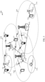
- FIG. 1 shows a wireless network 100 for communication, which may be an LTE-A network.
- the wireless network 100 includes a number of evolved node Bs (eNBs) 105 and other network entities.
- An eNB may be a station that communicates with the UEs and may also be referred to as a base station, a node B, an access point, and the like.
- Each eNB 105 may provide communication coverage for a particular geographic area.
- the term "cell" can refer to this particular geographic coverage area of an eNB and/or an eNB subsystem serving the coverage area, depending on the context in which the term is used.
- An eNB may provide communication coverage for a macro cell or a small cell, such as a pico cell or a femto cell, and/or other types of cell.
- a macro cell generally covers a relatively large geographic area (e.g., several kilometers in radius) and may allow unrestricted access by UEs with service subscriptions with the network provider.
- a small cell, such as a pico cell would generally cover a relatively smaller geographic area and may allow unrestricted access by UEs with service subscriptions with the network provider.
- a small cell such as a femto cell, would also generally cover a relatively small geographic area (e.g., a home) and, in addition to unrestricted access, may also provide restricted access by UEs having an association with the femto cell (e.g., LTEs in a closed subscriber group (CSG), LTEs for users in the home, and the like).
- An eNB for a macro cell may be referred to as a macro eNB.
- An eNB for a small cell may be referred to as a small cell eNB, a pico eNB, a femto eNB or a home eNB.
- the eNBs 105a, 105b and 105c are macro eNBs for the macro cells 110a, 110b and 110c, respectively.
- the eNBs 105x, 105y, and 105z are small cell eNBs, which may include pico or femto eNBs that provide service to small cells 110x, 110y, and 110z, respectively.
- An eNB may support one or multiple (e.g., two, three, four, and the like) cells.
- the wireless network 100 may support synchronous or asynchronous operation.
- the eNBs may have similar frame timing, and transmissions from different eNBs may be approximately aligned in time.
- the eNBs may have different frame timing, and transmissions from different eNBs may not be aligned in time.
- the UEs 115 are dispersed throughout the wireless network 100, and each UE may be stationary or mobile.
- a LTE may also be referred to as a terminal, a mobile station, a subscriber unit, a station, or the like.
- a LTE may be a cellular phone, a personal digital assistant (PDA), a wireless modem, a wireless communication device, a handheld device, a tablet computer, a laptop computer, a cordless phone, a wireless local loop (WLL) station, or the like.
- PDA personal digital assistant
- a UE may be able to communicate with macro eNBs, pico eNBs, femto eNBs, relays, and the like.
- a lightning bolt (e.g., communication links 125) indicates wireless transmissions between a UE and a serving eNB, which is an eNB designated to serve the UE on the downlink and/or uplink, or desired transmission between eNBs.
- Wired backhaul communications 134 indicate wired backhaul communications that may occur between eNBs.
- LTE/-A utilizes orthogonal frequency division multiplexing (OFDM) on the downlink and single-carrier frequency division multiplexing (SC-FDM) on the uplink.
- OFDM and SC-FDM partition the system bandwidth into multiple (K) orthogonal subcarriers, which are also commonly referred to as tones, bins, or the like.
- K orthogonal subcarriers
- Each subcarrier may be modulated with data.
- modulation symbols are sent in the frequency domain with OFDM and in the time domain with SC-FDM.
- the spacing between adjacent subcarriers may be fixed, and the total number of subcarriers (K) may be dependent on the system bandwidth.
- K may be equal to 72, 180, 300, 600, 900, and 1200 for a corresponding system bandwidth of 1.4, 3, 5, 10, 15, or 20 megahertz (MHz), respectively.
- the system bandwidth may also be partitioned into sub-bands.
- a sub-band may cover 1.08 MHz, and there may be 1, 2, 4, 8 or 16 sub-bands for a corresponding system bandwidth of 1.4, 3, 5, 10, 15, or 20MHz, respectively.
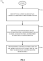
- FIG. 2 shows a block diagram of a design of a base station/eNB 105 and a UE 115, which may be one of the base stations/eNBs and one of the UEs in FIG. 1 .
- the eNB 105 may be the small cell eNB 105z in FIG. 1
- the UE 115 may be the UE 115z, which in order to access small cell eNB 105z, would be included in a list of accessible LTEs for small cell eNB 105z.
- the eNB 105 may also be a base station of some other type.
- the eNB 105 may be equipped with antennas 234a through 234t, and the LTE 115 may be equipped with antennas 252a through 252r.
- a transmit processor 220 may receive data from a data source 212 and control information from a controller/processor 240.
- the control information may be for the PBCH, PCFICH, PHICH, PDCCH, etc.
- the data may be for the PDSCH, etc.
- the transmit processor 220 may process (e.g., encode and symbol map) the data and control information to obtain data symbols and control symbols, respectively.
- the transmit processor 220 may also generate reference symbols, e.g., for the PSS, SSS, and cell-specific reference signal.
- a transmit (TX) multiple-input multiple-output (MIMO) processor 230 may perform spatial processing (e.g., precoding) on the data symbols, the control symbols, and/or the reference symbols, if applicable, and may provide output symbol streams to the modulators (MODs) 232a through 232t.
- Each modulator 232 may process a respective output symbol stream (e.g., for OFDM, etc.) to obtain an output sample stream.
- Each modulator 232 may further process (e.g., convert to analog, amplify, filter, and upconvert) the output sample stream to obtain a downlink signal.
- Downlink signals from modulators 232a through 232t may be transmitted via the antennas 234a through 234t, respectively.
- the antennas 252a through 252r may receive the downlink signals from the eNB 105 and may provide received signals to the demodulators (DEMODs) 254a through 254r, respectively.
- Each demodulator 254 may condition (e.g., filter, amplify, downconvert, and digitize) a respective received signal to obtain input samples.
- Each demodulator 254 may further process the input samples (e.g., for OFDM, etc.) to obtain received symbols.
- a MIMO detector 256 may obtain received symbols from all the demodulators 254a through 254r, perform MIMO detection on the received symbols if applicable, and provide detected symbols.
- a receive processor 258 may process (e.g., demodulate, deinterleave, and decode) the detected symbols, provide decoded data for the UE 115 to a data sink 260, and provide decoded control information to a controller/processor 280.
- a transmit processor 264 may receive and process data (e.g., for the PUSCH) from a data source 262 and control information (e.g., for the PUCCH) from the controller/processor 280.
- the transmit processor 264 may also generate reference symbols for a reference signal.
- the symbols from the transmit processor 264 may be precoded by a TX MIMO processor 266 if applicable, further processed by the modulators 254a through 254r (e.g., for SC-FDM, etc.), and transmitted to the eNB 105.
- the uplink signals from the UE 115 may be received by the antennas 234, processed by the demodulators 232, detected by a MIMO detector 236 if applicable, and further processed by a receive processor 238 to obtain decoded data and control information sent by the UE 115.
- the processor 238 may provide the decoded data to a data sink 239 and the decoded control information to the controller/processor 240.
- the controllers/processors 240 and 280 may direct the operation at the eNB 105 and the UE 115, respectively.
- the controller/processor 240 and/or other processors and modules at the eNB 105 may perform or direct the execution of various processes for the techniques described herein.
- the controllers/processor 280 and/or other processors and modules at the UE 115 may also perform or direct the execution of various processes for the techniques described herein.
- the memories 242 and 282 may store data and program codes for the eNB 105 and the LTE 115, respectively.
- a scheduler 244 may schedule UEs for data transmission on the downlink and/or uplink.
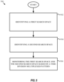
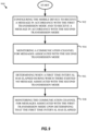
- FIG. 3 is a block diagram illustrating a method for setting a second search space according to one aspect of the present disclosure. Aspects of method 300 may be implemented with the aspects of this disclosure described with respect to FIGS. 1-2 and 10-11 , such as a base station. The example blocks will also be described with respect to eNB 105 as illustrated in FIG. 10.
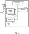
- FIG. 10 is a block diagram illustrating eNB 105 configured according to one aspect of the present disclosure.
- eNB 105 includes the structure, hardware, and components as illustrated for eNB 105 of FIG. 2 .
- eNB 105 includes controller/processor 240, which operates to execute logic or computer instructions stored in memory 242, as well as controlling the components of eNB 105 that provide the features and functionality of eNB 105.
- Wireless radios 1000a-t includes various components and hardware, as illustrated in FIG. 2 for eNB 105, including modulator/demodulators 232a-t, MIMO detector 236, receive processor 238, transmit processor 220, and TX MIMO processor 230.
- method 300 includes, at block 302, identifying, by a processor, a first search space configuration for a first search space.
- eNB 105 may, under control of controller/processor 240, identify a first search space configuration for a first search space.
- the first search space may include one or more locations where unicast control information may be retrieved by a mobile device.
- a search space may refer to a set of control channel element (CCE) locations or enhanced CCE (ECCE) locations where a UE may find its physical downlink control channel (PDCCH), enhanced PDCCH (EPDCCH), or enhanced MTC (eMTC) PDCCH (MPDCCH), and, in particular, downlink control information (DCI) in the PDCCH.
- the first search space may be a UE-specific search space.
- a UE-specific search space may be a search space where a base station provides control information that is capable of being decoded by only the UE for which the control information was intended.
- control information in the first search space may be termed unicast control information because the control information in the first search space may be used to effectuate unicast communication between the base station and the UE.
- control information transmitted in the first search space may include at least one of transmitter power control (TPC) information and an acknowledgement, or negative acknowledgement, indicating whether a message was received correctly or in error.
- TPC transmitter power control
- the first search space may be pre-established, such as by a specification.
- a base station may, for example under control of controller/processor 240, identify the first search space by identifying the pre-established search space to be used to communicate UE-specific control information.
- a LTE may identify, for example under control of controller/processor 280, the first search space by identifying the pre-established search space which is being used to communicate UE-specific control information.
- the base station may, for example under control of controller/processor 240 and/or wireless radios 1000a-t and/or antennas 234a-t, inform the UE of the first search space configuration.
- identifying the first search space by the UE may include receiving, for example under control of controller/processor 280 and/or wireless radios 1 100a-r and/or antennas 252a-r, a message from the base station that specifies the first search space.
- method 300 includes setting, by the processor, a second search space configuration for a second search space based, at least in part, on the first search space configuration.
- eNB 105 may, under control of controller/processor 240 and/or wireless radios 1000a-t, set a second search space configuration for a second search space based, at least in part, on the first search space configuration.
- the second search space may include one or more locations where control information for more than one mobile device may be retrieved by the mobile device.
- the second search space may be a search space common for a plurality of UEs, i.e., the common search space may not be specific to a particular UE.
- a common search space may be a search space where a base station provides control information that is capable of being decoded by many LTEs rather than being capable of decoding by only the LTE for which the control information was intended.
- the control information in the second search space may be termed broadcast control information because the control information in the second search space may be used to effectuate broadcast communication between the base station and a plurality of UEs.
- control information transmitted in the second search space may include at least one of TPC information and ACK/NACK information.
- the common search space may be used as a fallback search space when information is not available or not decodable by the UE in the UE-specific search space.
- the common search space may be configured with a larger repetition level than the UE-specific search space, such that it can be used by the UE when the UE-specific search space is not decodable by the UE.
- the common search space may be used to provide system information, paging, or group power control.
- setting the second search space configuration based, at least in part, on the first search space configuration may include setting a frequency band for the second search space equal to a first frequency band that overlaps with a frequency band of the first search space.
- eNB 105 may, under control of controller/processor 240 and/or wireless radios 1000a-t, set a frequency band for the second search space equal to a first frequency band that overlaps with a frequency band of the first search space.
- the first search space may include a first frequency band.
- the frequency band may be a narrow frequency band. In some aspects of the disclosure, the narrow frequency band may range from as small as approximately 1 MHz to as large as approximately 30 MHz.
- setting the second search space configuration based, at least in part, on the first search space configuration may include setting the second search space to the same 1.4 MHz range of the particular frequency bandwidth.
- the base station may transmit LTE-specific control information, fallback control information, or control information common for a plurality of devices in the same frequency range of a particular bandwidth.
- the base station may, under control of controller/processor 240 and/or wireless radios 1000a-t and/or antennas 234a-t, code the UE-specific control information and the common control information differently and then inform a UE receiving the control information of how the UE-specific and common control information was coded so that the receiving UE can properly decode the appropriate information, where the encoding may include different aggregation or repetition level, different scrambling sequence, different number of candidates.
- the first search space may include a first number of candidates and the second search space may include a second number of candidates.
- setting the second search space configuration based, at least in part, on the first search space configuration may include setting, in a first transmission time interval (TTI), such as a subframe, a frequency band for the second search space equal to a first frequency band that overlaps with a frequency band of the first search space and setting, in a second TTI, the frequency band for the second search space equal to a second frequency band that does not overlap with the frequency band of the first search space.
- TTI transmission time interval
- eNB 105 may, under control of controller/processor 240 and/or wireless radios 1000a-t, set, in a first TTI, a frequency band for the second search space equal to a first frequency band that overlaps with a frequency band of the first search space and set, in a second TTI, the frequency band for the second search space equal to a second frequency band that does not overlap with the frequency band of the first search space.
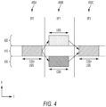
- FIG. 4 provides a diagram that illustrates an example of the setting of the second search space based on the first search space according to one aspect of the present disclosure. Three different TTIs 450 are illustrated in FIG. 4 . Each TTI occupies a distinct time interval. In other words, no two TTIs overlap in time.
- transmission of the UE-specific control information in the UE-specific search space (USS) and transmission of the common control information in the common search space (CSS) may include hopped transmission.
- the UE-specific control information and the common control information may be coded differently. Therefore, the UE-specific control information and the common control information may have distinct data patterns.
- TTI 450A the UE-specific control information and the common control information, both of which may be coded differently, may be in the same narrow frequency band 410.
- TTI 450B the UE-specific control information may be in narrow frequency band 420 and the common control information may be in narrow frequency band 430.
- the UE-specific control information and the common control information may again be in the same narrow frequency band 410. Therefore, a base station implementing hopped transmission to transmit UE-specific control information and common control information may transmit both in the same frequency band in a first TTI so that the USS and the CSS overlap. Then the base station may transmit both in different frequency bands in a second TTI so that the USS and the CSS do not overlap. In subsequent TTIs, the UE-specific control information and common control information may be included in the same or a different frequency band similar to as was done in the first or second TTI. In some cases, a UE may decode the CSS only when USS and CSS overlap in the same frequency band.
- setting the second search space configuration based, at least in part, on the first search space configuration may include setting the second search space based on parameters that do not include a parameter that was used to set the first search space.
- eNB 105 may, under control of controller/processor 240 and/or wireless radios 1000a-t, set the second search space based on parameters that do not include a parameter that was used to set the first search space. In other words, the use of a parameter that was used to set the first search space may be avoided when setting the second search space.
- the first search space may include candidates that were set based on an identifier of the mobile device, such as a cell radio network temporary identifier (C-RNTI) which may be stored in memory 242.
- C-RNTI cell radio network temporary identifier
- candidates of the second search space may be set based on parameters that do not include the identifier of the mobile device.
- the base station may avoid using the C-RNTI when setting the second search space.
- method 300 includes transmitting, by the processor, control information to the mobile device in at least one of the first search space and the second search space.
- eNB 105 may, under control of controller/processor 240 and/or wireless radios 1000a-t and/or antennas 234a-t, transmit control information to the mobile device in at least one of the first search space and the second search space.
- the base station may transmit UE-specific control information and common control information in the same frequency band in a particular bandwidth when the frequency band for the second search space is set to overlap with the frequency band of the first search space in a particular bandwidth.
- the base station may transmit the UE-specific control information and the common control information in a hopped manner, as discussed above and with reference to FIG. 4 .
- the base station may transmit LTE-specific control information in a first search space and common control information in a second search space that the base station set while avoiding the use of a UE identifier as disclosed above.
- transmitting, such as at block 306, may include transmitting at least one of a grant for uplink transmission, a grant for downlink transmission, a fallback grant that includes fallback control information, TPC information, and an acknowledgement, or negative acknowledgement, indicating whether a message was received correctly or in error.
- transmitting, such as at block 306, may include transmitting, in the first search space, control information associated with a first transmission mode, and transmitting, in the second search space, control information associated with a second transmission mode.
- a UE may be configured to determine the first and second search spaces used for transmission of UE-specific control information and common control information, respectively, and to receive the transmitted UE-specific control information and common control information.
- LTE 115 may, under control of controller/processor 280 and/or wireless radios 1100a-r and/or antennas 252a-r, determine and identify the first and second search spaces used for transmission of UE-specific control information and common control information, respectively, and receive the transmitted UE-specific control information and common control information.
- a UE may be configured to identify a first search space configuration for a first search space.
- a LTE may receive from a base station the configuration information for the first search space. Accordingly, the UE may identify the first search space based on the information received from the base station.
- the UE may be configured to determine the second search space configuration based, at least in part, on the first search space configuration.
- LTE 115 may, under control of controller/processor 280 and/or wireless radios 1100a-r and/or antennas 252a-r, determine the second search space configuration based, at least in part, on the first search space configuration.
- the UE may be configured to determine that the second search space was established by setting a frequency band for the second search space equal to a first frequency band that overlaps with a frequency band of the first search space.
- the UE may be configured to determine that, in a first TTI, a frequency band for the second search space was set equal to a first frequency band that overlaps with a frequency band of the first search space and that, in a second TTI, the frequency band for the second search space was set equal to a second frequency band that does not overlap with the frequency band of the first search space.
- the LTE may be configured to determine that the first search space includes candidates that were set based on an identifier of the mobile device, and that candidates of the second search space were set based on parameters that do not include the identifier of the mobile device.
- the LTE may determine the second search space based on information provided by the base station.
- LTE 115 may, under control of controller/processor 280 and/or wireless radios 1100a-r, determine the second search space based on information provided by the base station.
- the base station may inform the UE of the configuration for the second search space.
- an agreement may be established between the base station and the LTE as to how the second search space will be configured such that the base station only sends the first search space configuration information and, based on that information, the LTE determines the second search space configuration.
- the UE may receive a message which indicates how the second search space was configured and if the second search space configuration was set based on the first search space configuration.
- the UE may monitor the first and second search spaces and receive control information from the base station in at least one of the first search space and the second search space.
- UE 115 may, under control of controller/processor 280 and/or wireless radios 1100a-r and/or antennas 252a-r, monitor the first and second search spaces and receive control information from the base station in at least one of the first search space and the second search space.
- the LTE may receive UE-specific control information and common control information in the same frequency band in a particular bandwidth when the frequency band for the second search space was set to overlap with the frequency band of the first search space in a particular bandwidth.
- the UE may receive UE-specific control information in a first search space and common control information in a second search space that the base station set while avoiding the use of a UE identifier as disclosed above.
- the UE may receive the UE-specific control information and the common control information in a hopped manner, as discussed above and with reference to FIG. 4 .
- UE-specific control information may have priority over common control information.
- the UE may be configured to monitor the PDCCH for LTE-specific control information in all TTIs, such as TTIs 450A, 450B, and 450C, and to monitor the PDCCH for common control information in a subset of all of the TTIs, such as TTIs 450A and 450C.
- the common control information may have priority, such as when the base station does not transmit UE-specific control information or the LTE does not receive UE-specific control information.
- the LTE may be configured to monitor for common control information in all TTIs, such as TTIs 450A, 450B, and 450C.
- the LTE may be configured to monitor the USS or the CSS based on whether or not semi-persistent scheduling (SPS) is being utilized for communication by the base station, such as under control of controller/processor 240 and/or wireless radios 1000a-t and/or antennas 234a-t and/or scheduler 244.
- SPS semi-persistent scheduling
- a UE may monitor only the USS when SPS is not being used, but may monitor both the USS and the CSS when SPS is being used.
- the base station may, for example under control of controller/processor 240 and/or wireless radios 1000a-t and/or antennas 234a-t and/or scheduler 244, transmit ACK/NACK and TPC information using DCI 3/3A when SPS is being used.
- the bitwidth for ACK/NACK and the bitwidth for TPC can be mandated to be the same or can be configured differently.
- FIG. 5 is a block diagram illustrating a method for monitoring search spaces according to one aspect of the present disclosure. Aspects of method 500 may be implemented with the aspects of this disclosure described with respect to FIGS. 1-2 and 10-11 , such as a UE. The example blocks will also be described with respect to LTE 115 as illustrated in FIG. 9.
- FIG. 9 is a block diagram illustrating LTE 115 configured according to one aspect of the present disclosure.
- UE 115 includes the structure, hardware, and components as illustrated for UE 115 of FIG. 2 .
- UE 115 includes controller/processor 280, which operates to execute logic or computer instructions stored in memory 282, as well as controlling the components of UE 115 that provide the features and functionality of LTE 115.
- LTE 115 under control of controller/processor 280, transmits and receives signals via wireless radios 1100a-r and antennas 252a-r.
- Wireless radios 1100a-r includes various components and hardware, as illustrated in FIG. 2 for LTE 115, including modulator/demodulators 254a-r, MIMO detector 256, receive processor 258, transmit processor 264, and TX MIMO processor 266.
- method 500 includes, at block 502, identifying, by a processor, a first search space.
- UE 115 may, under control of controller/processor 280, identify a first search space.
- the first search space may include one or more locations from where unicast control information may be retrieved.
- a LTE may receive, for example under control of controller/processor 280 and/or wireless radios 1100a-r and antennas 252a-r, from a base station configuration information for the first search space. Accordingly, the UE may identify the first search space based on the information received from the base station.
- method 500 includes identifying, by the processor, a second search space.
- UE 115 may, under control of controller/processor 280, identify a second search space.
- the second search space may include one or more locations from where control information for more than one mobile device may be retrieved.
- a UE may receive, for example under control of controller/processor 280 and/or wireless radios 1100a-r and antennas 252a-r, from a base station configuration information for the second search space. Accordingly, the LTE may identify the second search space based on the information received from the base station.
- method 500 includes monitoring, by the processor, the first search space and the second search space based on a time-division multiplexed pattern.
- LTE 115 may, under control of controller/processor 280 and/or wireless radios 1100a-r and/or antennas 252a-r, monitor the first search space and the second search space based on a time-division multiplexed pattern.
- the USS and the CSS may occupy different non-overlapping narrow frequency bands of a particular communication bandwidth, and monitoring of the first search space and the second search space may be based on a time-division multiplexed pattern.
- monitoring of the first search space and the second search space may be based on a time-division multiplexed pattern.
- monitoring may include a UE, for example under control of controller/processor 280 and/or wireless radios 1100a-r and/or antennas 252a-r, monitoring the first search space for unicast control information in the first search space that the processor is capable of decoding, determining when a first time interval has elapsed during which there existed no unicast control information in the first search space that the processor is capable of decoding, and monitoring the second search space upon determining that the first time interval has elapsed.
- monitoring may include determining a signal to noise ratio (SNR) value, and monitoring the first search space and/or the second search space based on the SNR determination.
- SNR signal to noise ratio
- the first search space may be monitored upon determining that the SNR value exceeds a threshold, and the second search space may be monitored upon determining that the SNR value does not exceed a threshold, or vice versa.
- the UE may be configured to monitor the USS, i.e., the first search space, regardless of whether there is control information in the CSS, i.e., the second search space.
- the UE may keep track of how much time has passed since the last time UE-specific control information was provided in the USS.
- the UE may compare the time with a threshold, which may be pre-defined, user-provided, or automatically generated dynamically.
- the threshold may represent the maximum amount of the time the UE may monitor the USS before transitioning to monitoring of the CSS.
- the UE may transition to monitoring of the CSS for common control information.
- the CSS may be monitored when the SNR is determined to be below a threshold, and the USS may be monitored when the SNR is determined to be above a threshold.
- the CSS may serve as a fallback search space to be searched when UE-specific control information is not received, for example, as a result of faulty encoding or errors in transmission or reception.
- monitoring the first search space and the second search space based on a time-division multiplexed pattern may include configuring the UE to monitor the CSS for common control information in the first TTI of every radio frame and monitor the USS for UE-specific control information in the remainder of the TTIs of every radio frame.
- UE 115 may, under control of controller/processor 280 and/or wireless radios 1100a-r and/or antennas 252a-r, configure itself to monitor the CSS for common control information in the first TTI of every radio frame and monitor the USS for UE-specific control information in the remainder of the TTIs of every radio frame.
- monitoring may also include monitoring the USS for LTE-specific control information in every TTI and monitoring the CSS for common control information in every Nth TTI, such as every 3 rd TTI, or every 5 th TTI.
- a LTE may monitor a communication channel for a first type of information (for example DCI 1A) in the common search space, CSS, and for a second type of information (for example DCI 1B, or the equivalent in other transmission modes) in the UE-specific search space, USS.
- a first type of information for example DCI 1A
- a second type of information for example DCI 1B, or the equivalent in other transmission modes
- the first type of information may be the same as the second type of information.
- a UE may monitor the common search space for control information associated with a first transmission mode and may monitor the UE-specific search space for control information associated with a second transmission mode.
- FIG. 6 is a block diagram illustrating a method for setting search spaces according to one aspect of the present disclosure. Aspects of method 600 may be implemented with the aspects of this disclosure described with respect to FIGS. 1-2 and 10-11 , such as a base station. The example blocks will also be described with respect to eNB 105 as illustrated in FIG. 10 .
- method 600 includes, at block 602, setting, by a processor, a first search space configuration for a first search space and a second search space configuration for a second search space based, at least in part, on a transmission power required by a mobile device for reception, wherein the first search space comprises one or more locations where unicast control information may be retrieved by the mobile device, and wherein the second search space comprises one or more locations where control information for more than one mobile device may be retrieved by the mobile device.
- eNB 105 may, under control of controller/processor 240 and/or wireless radios 1000a-t and/or antennas 234a-t, set a first search space configuration for a first search space and a second search space configuration for a second search space based, at least in part, on a transmission power required by a mobile device for reception.
- different UEs capable of communicating with a base station may require different repetition/aggregation levels for communications from the base station.
- one UE capable of communicating with a base station may be a LTE located deep in a basement of a residence or behind layers of concrete of a building, such as a utility meter.
- a repetition level of 2 means that the communication must be transmitted 2 times
- a repetition level of N means that the communication must be transmitted N times.
- the base station may set a first search space configuration for a first search space and a second search space configuration for a second search space based, at least in part, on the repetition levels associated with a mobile device, i.e., a transmission power required by a mobile device for reception.
- the repetition level may be referred to as a bundle size to associate with communication.
- a base station may configure the CSS for a UE with a larger repetition level than that necessary for the UE.
- This larger repetition level may be monitored by the UE in fallback mode, for example, after detecting a drop in SNR level.
- the bundle size configuration i.e., the repetition/aggregation level
- the bundle size configuration may be obtained by the LTE in different ways.
- the bundle size configuration may be obtained via Radio Resource Control (RRC) signaling.
- RRC Radio Resource Control
- the bundle size configuration associated with the common search space may be obtained via RRC signaling, which may be different than the bundle size configuration for the UE-specific search space.
- a UE may receive a separate RRC configuration for the common search space.
- the bundle size configuration may also be obtained for CSS by setting it to the same value as the bundle size for the USS.
- the bundle size configuration may be obtained by broadcast messages.
- method 600 includes transmitting, by the processor, control information to the mobile device in at least one of the first search space and the second search space.
- eNB 105 may, under control of controller/processor 240 and/or wireless radios 1000a-t and/or antennas 234a-t, transmit control information to the mobile device in at least one of the first search space and the second search space.
- transmission may include retransmission of the control information in the USS or the CSS based on the repetition level associated with the USS or the CSS.
- the base station may be configured to retransmit, a first number of times, control information to the mobile device in the first search space, i.e., the USS, wherein the first number of times to retransmit is determined based on the transmission power required for reception by the mobile device, i.e., the repetition level associated with the mobile device.
- the base station may be configured to retransmit, a second number of times, control information to the mobile device in the second search space, i.e., the CSS, wherein the second number of times to retransmit is determined based on the transmission power required for reception by multiple mobile devices, and wherein the second number of times is different than the first number of times.
- the transmission power required for reception by multiple mobile devices may be the worst case repetition level required by any device which is an intended recipient of the common control information in the CSS.
- a LTE may be configured to receive a USS associated with a first repetition level and receive a CSS associated with a second repetition level.
- UE 115 may, under control of controller/processor 280 and/or wireless radios 1100a-r and/or antennas 252a-r, receive a USS associated with a first repetition level and receive a CSS associated with a second repetition level.
- a LTE may receive control information in a USS, where the control information in the USS has been retransmitted a first number of times determined based on the transmission power required for reception by the UE, i.e., the repetition level associated with the LTE.
- the LTE may receive control information in a CSS, where the control information in the CSS has been retransmitted a second number of times determined based on the transmission power required for reception by multiple UEs, such as the worst case repetition level required by any device which is an intended recipient of the common control information in the CSS.
- the base station may, for example under control of controller/processor 240 and/or wireless radios 1000a-t and/or antennas 234a-t, inform the UE of the repetition levels associated with the USS and the CSS.
- the LTE may, for example under control of controller/processor 280 and/or wireless radios 1100a-r and/or antennas 252a-r, determine the repetition level associated with the USS and the CSS based on information received in a message from the base station or information processed by the UE at the UE.
- FIG. 7 is a block diagram illustrating a method for wireless communication using multiple transmission modes according to one aspect of the present disclosure. Aspects of method 700 may be implemented with the aspects of this disclosure described with respect to FIGS. 1-2 and 10-11 , such as a UE. The example blocks will also be described with respect to UE 115 as illustrated in FIG. 11 .
- FIG. 7 provides a block diagram illustrating a method for wireless communication using multiple transmission modes according to one aspect of the present disclosure.
- method 700 includes, at block 702, configuring a mobile device to receive a message in accordance with a first transmission mode.
- UE 115 may, under control of controller/processor 280 and/or wireless radios 1100a-r and/or antennas 252a-r, configure itself to receive a message in accordance with a first transmission mode.
- a mobile device may be configured to receive a message, i.e., a grant, providing information regarding a first transmission mode, such as transmission mode TM1.
- TM1 transmission mode
- the mobile device may be configured to receive grants of size N.
- configuring the mobile device to receive a grant with information regarding the first transmission mode may also configure the mobile device to receive grants with information regarding other transmission modes for which their associated grants are also of size N.
- the mobile device may be configured to receive grants associated with any transmission mode so long as the grants are of the same size N.
- method 700 includes receiving a first message in accordance with the first transmission mode.
- LTE 115 may, under control of controller/processor 280 and/or wireless radios 1100a-r and/or antennas 252a-r, receive a first message in accordance with the first transmission mode.
- a mobile device may be configured to receive a grant of size N which provides information regarding the first transmission mode.
- method 700 includes receiving a second message in accordance with a second transmission mode and that includes information to process in collaboration with information received in the first message, wherein a message received in accordance with a second transmission mode includes the information received in the first message and the information received in the second message.
- LTE 115 may, under control of controller/processor 280 and/or wireless radios 1100a-r and/or antennas 252a-r, receive a second message that includes information to process in collaboration with information received in the first message.
- a message received in accordance with a second transmission mode may be a grant which provides information regarding a transmission mode different than the first transmission mode and has a size that is different than the grant of size N which provides information regarding the first transmission mode.
- the grant which provides information regarding a transmission mode different than the first transmission mode may have a size M, which may be larger than N.
- the grant associated with the second transmission mode may normally include the information received in the first message and the information received in the second message.
- a mobile device configured to receive grants associated with second transmission mode would receive a grant having a size M and including the information received in the first message and the information received in the second message all within the grant message.
- the mobile device is configured to receive grants in accordance with the first transmission mode, the mobile device cannot properly receive the grant associated with the second transmission mode because it is not configured to read grants that large.
- the mobile device in order for a mobile device configured to receive grants in accordance with the first transmission mode, such as at block 702, to receive all the information that would have been received in a grant associated with the second transmission mode, the mobile device receives a grant in accordance with the first transmission mode, such as at block 704, and then receives the remainder of the information that would have been included in the grant associated with the second transmission mode in the second message, such as at block 706.
- the information in the grant received at block 704 and the information in the second message may make up all the information that would have been included in a grant associated with the second transmission mode such that when the information received in the second message is processed in collaboration with the information received in the first message, the mobile device is essentially processing information that would have been received entirely within a grant associated with the second transmission mode.
- the mobile device By obtaining the additional information that would be required for operation in the second transmission mode via a second message, the mobile device is able to maintain its original configuration, i.e., its configuration to receive grants associated with the first transmission mode and having original size N.
- the additional information is not included in the grants it receives because the grants cannot contain the additional information and because the mobile device is not configured to receive larger grants. Instead the additional information is received via a second message, such as at block 706.
- the LTE may receive the TPMI/PMI information in the second message.
- the second message may inform the UE to use the last reported PMI to obtain its precoding matrix.
- the second message may be a separate message received by the LTE from the base station, or a message generated by the UE based on processing of information received by the UE.
- the UE may monitor for fallback grant (M1A), and additionally monitor for the other grant.
- M1A fallback grant
- the information in the second message may include information which informs the mobile device of where the mobile device may receive information regarding the precoding matrix to use for decoding data.
- the second message may inform the LTE that the information regarding the precoding matrix cycles across TTIs, such as, for example, informing the UE that precoder 1 will be in TTI 1, precoder 2 will be in TTI 2, precoder 3 will be in TTI 3, and so on.
- the UE may receive the scrambling sequence information in the second message.
- the second message may specify a scrambling sequence to use.
- the second message may be a separate message received by the UE from the base station, or a message generated by the UE based on processing of information received by the UE.
- the information in the second message may include information which informs the mobile device of where the mobile device may receive information regarding the scrambling sequence to use, such as where in a radio frame the information may be located or provided by the base station.
- a base station may be configured to transmit a first message in accordance with a first transmission mode and to transmit a second message in accordance with a second transmission mode, wherein the second message includes information to process in collaboration with information in the first message, and wherein the second message includes the information in the first message.
- eNB 105 may, under control of controller/processor 240 and/or wireless radios 1000a-t and/or antennas 234a-t, transmit a first message in accordance with a first transmission mode and to transmit a second message in accordance with a second transmission mode, wherein the second message includes information to process in collaboration with information in the first message, and wherein the second message includes the information in the first message.
- FIG. 8 is a block diagram illustrating a method for wireless communication using multiple transmission modes according to another aspect of the present disclosure. Aspects of method 800 may be implemented with the aspects of this disclosure described with respect to FIGS. 1-2 and 10-11 , such as a UE. The example blocks will also be described with respect to UE 115 as illustrated in FIG. 11 .
- method 800 includes, at block 802, transmitting, by a mobile device, a message indicating the mobile device's capability to receive messages in accordance with a first or second transmission mode.
- LTE 115 may, under control of controller/processor 280 and/or wireless radios 1100a-r and/or antennas 252a-r, transmit a message indicating the mobile device's capability to receive messages in accordance with a first or second transmission mode.
- the UE may transmit a message to the base station indicating that it is capable of receiving a grant in accordance with other transmission modes, such as TM6 or TM9, in addition to being capable of receiving grants in accordance with a first transmission mode, such as TM1 or TM2.
- method 800 includes configuring the mobile device to receive a message in accordance with the first transmission mode and to receive a message in accordance with the second transmission mode.
- LTE 115 may, under control of controller/processor 280 and/or wireless radios 1100a-r and/or antennas 252a-r, configure itself to receive a message in accordance with the first transmission mode and to receive a message in accordance with the second transmission mode.
- the UE may be configured to receive grants providing information regarding a first transmission mode, such as TM1, and a second transmission mode, such as TM6.
- method 800 includes determining whether a message in a communication channel is associated with the first transmission mode or the second transmission mode.
- LTE 115 may, under control of controller/processor 280 and/or wireless radios 1100a-r and/or antennas 252a-r, determine whether a message in a communication channel is associated with the first transmission mode or the second transmission mode.
- the UE may identify that a grant is being provided to the UE in a communication channel and determine, for example, based on the size of the grant, whether the grant is associated with the first or second transmission mode.
- method 800 includes receiving the message and processing the received message based on the determination of whether the message is associated with the first transmission mode or the second transmission mode.
- UE 115 may, under control of controller/processor 280 and/or wireless radios 1100a-r and/or antennas 252a-r, receive the message and process the received message based on the determination of whether the message is associated with the first transmission mode or the second transmission mode. For example, if the grant was associated with a first transmission mode, such as TM1, having a size of N bits, then the mobile device will process the N bits of the grant.
- a first transmission mode such as TM1
- the mobile device will process the M bits of the grant. Accordingly, the mobile device is capable of reconfiguring itself to receive and process grants based on the specific properties of the grants.
- FIG. 9 is a block diagram illustrating a method for wireless communication using multiple transmission modes according to yet another aspect of the present disclosure. Aspects of method 900 may be implemented with the aspects of this disclosure described with respect to FIGS. 1-2 and 10-11 , such as a UE. The example blocks will also be described with respect to UE 115 as illustrated in FIG. 11 .
- method 900 includes, at block 902, configuring the mobile device to receive a message in accordance with the first transmission mode and to receive a message in accordance with the second transmission mode.
- LTE 115 may, under control of controller/processor 280 and/or wireless radios 1100a-r and/or antennas 252a-r, configure itself to receive a message in accordance with the first transmission mode and to receive a message in accordance with the second transmission mode.
- the UE may be configured to receive grants providing information regarding a first transmission mode, such as TM1, and a second transmission mode, such as TM6.
- method 900 includes monitoring a communication channel for messages associated with the second transmission mode.
- UE 115 may, under control of controller/processor 280 and/or wireless radios 1100a-r and/or antennas 252a-r, monitor a communication channel for messages associated with the second transmission mode.
- the UE may monitor a communication channel for grants associated with a second transmission mode, such as TM6 or TM9.
- method 900 includes determining when a first time interval has elapsed during which there existed no message associated with the second transmission mode.
- UE 115 may, under control of controller/processor 280 and/or wireless radios 1100a-r and/or antennas 252a-r, determine when a first time interval has elapsed during which there existed no message associated with the second transmission mode.
- method 900 includes monitoring the communication channel for messages associated with the first transmission mode upon determining that the first time interval has elapsed.
- UE 115 may, under control of controller/processor 280 and/or wireless radios 1100a-r and/or antennas 252a-r, monitor the communication channel for messages associated with the first transmission mode upon determining that the first time interval has elapsed.
- larger grants such as those associated with TM6 or TM9
- the UE may be configured to monitor for larger grants first.
- the UE may keep track of how much time has passed since the last time a grant associated with second transmission mode was provided in the communication channel.
- the UE may compare the time with a threshold, which may be pre-defined, user-provided, or automatically generated dynamically.
- the threshold may represent the maximum amount of the time the LTE may monitor the communication channel for a grant associated with a second transmission mode before transitioning to monitoring the communication for a grant associated with the first transmission mode, such as TM1 or TM2.
- the UE may transition to monitoring of the communication channel for grants associated with the first transmission mode.
- monitoring may also be dependent on the SNR.
- monitoring may include determining a signal to noise ratio (SNR) value, monitoring a communication channel for messages associated with the first transmission mode upon determining that the SNR value exceeds a threshold, and monitoring the communication channel for messages associated with the second transmission mode upon determining that the SNR value does not exceed a threshold.
- monitoring may include determining a signal to noise ratio (SNR) value, monitoring a communication channel for messages associated with the first transmission mode upon determining that the SNR value does not exceed a threshold, and monitoring the communication channel for messages associated with the second transmission mode upon determining that the SNR value exceeds a threshold.
- SNR signal to noise ratio
- the LTE may monitor the communication channel for only grants that include the additional information required by the secondary transmission modes, such as TPMI information in the case of TM6 and scrambling information in the case of TM9.
- the grant transmitted by the base station and received by the UE may still include the additional bits required by the grant to include the additional information relevant to the secondary transmission modes, such as TM6 or TM9, but not a transmission mode being associated with a smaller grant, such as TM1 or TM2.
- the LTE may change the method for wireless communication using multiple transmission modes, such as method 700, 800, or 900, based on coverage requirements, such as the repetition levels associated with UEs in the communication system.
- monitoring employed by the UE may also be dependent on the coverage enhancement requirements, such as the repetition levels associated with UEs in the communication system.
- monitoring may include determining the coverage enhancement requirement, monitoring a communication channel for messages associated with the first transmission mode upon determining that the coverage enhancement value exceeds a threshold, and monitoring the communication channel for messages associated with the second transmission mode upon determining that the coverage enhancement value does not exceed a threshold.
- monitoring may include determining the coverage enhancement requirement, monitoring a communication channel for messages associated with the first transmission mode upon determining that the coverage enhancement value does not exceed a threshold, and monitoring the communication channel for messages associated with the second transmission mode upon determining that the coverage enhancement value exceeds a threshold.
- identification of the second search space may be based, at least in part, on the determined coverage enhancement level.
- coverage enhancement levels may impact how a search space is set by a base station. For example, after a coverage enhancement level is determined, a second search space may be set based at least in part on the determined coverage enhancement level.
- the functional blocks and modules in the FIGS. may comprise processors, electronics devices, hardware devices, electronics components, logical circuits, memories, software codes, firmware codes, etc., or any combination thereof.
- DSP digital signal processor
- ASIC application specific integrated circuit
- FPGA field programmable gate array
- a general-purpose processor may be a microprocessor, but in the alternative, the processor may be any conventional processor, controller, microcontroller, or state machine.
- a processor may also be implemented as a combination of computing devices, e.g., a combination of a DSP and a microprocessor, a plurality of microprocessors, one or more microprocessors in conjunction with a DSP core, or any other such configuration.
- a software module may reside in RAM memory, flash memory, ROM memory, EPROM memory, EEPROM memory, registers, hard disk, a removable disk, a CD-ROM, or any other form of storage medium known in the art.
- An exemplary storage medium is coupled to the processor such that the processor can read information from, and write information to, the storage medium.
- the storage medium may be integral to the processor.
- the processor and the storage medium may reside in an ASIC.
- the ASIC may reside in a user terminal.
- the processor and the storage medium may reside as discrete components in a user terminal.
- the functions described may be implemented in hardware, software, firmware, or any combination thereof. If implemented in software, the functions may be stored on or transmitted over as one or more instructions or code on a computer-readable medium.
- Computer-readable media includes both computer storage media and communication media including any medium that facilitates transfer of a computer program from one place to another. Computer-readable storage media may be any available media that can be accessed by a general purpose or special purpose computer.
- such computer-readable media can comprise RAM, ROM, EEPROM, CD-ROM or other optical disk storage, magnetic disk storage or other magnetic storage devices, or any other medium that can be used to carry or store desired program code means in the form of instructions or data structures and that can be accessed by a general-purpose or special-purpose computer, or a general-purpose or special-purpose processor.
- a connection may be properly termed a computer-readable medium.
- the software is transmitted from a website, server, or other remote source using a coaxial cable, fiber optic cable, twisted pair, or digital subscriber line (DSL), then the coaxial cable, fiber optic cable, twisted pair, or DSL, are included in the definition of medium.
- DSL digital subscriber line
- Disk and disc includes compact disc (CD), laser disc, optical disc, digital versatile disc (DVD), floppy disk and blu-ray disc where disks usually reproduce data magnetically, while discs reproduce data optically with lasers. Combinations of the above should also be included within the scope of computer-readable media.
- the term "and/or,” when used in a list of two or more items, means that any one of the listed items can be employed by itself, or any combination of two or more of the listed items can be employed.
- the composition can contain A alone; B alone; C alone; A and B in combination; A and C in combination; B and C in combination; or A, B, and C in combination.
Description
- Aspects of the present disclosure relate generally to wireless communication systems and, more particularly, to the design of search spaces and grants to improve machine type communication (MTC) in wireless communication systems.
- Wireless communication networks are widely deployed to provide various communication services such as voice, video, packet data, messaging, broadcast, and the like. These wireless networks may be multiple-access networks capable of supporting multiple users by sharing the available network resources. Such networks, which are usually multiple access networks, support communications for multiple users by sharing the available network resources. One example of such a network is the Universal Terrestrial Radio Access Network (UTRAN). The UTRAN is the radio access network (RAN) defined as a part of the Universal Mobile Telecommunications System (UMTS), a third generation (3G) mobile phone technology supported by the 3rd Generation Partnership Project (3GPP). Examples of multiple-access network formats include Code Division Multiple Access (CDMA) networks, Time Division Multiple Access (TDMA) networks, Frequency Division Multiple Access (FDMA) networks, Orthogonal FDMA (OFDMA) networks, and Single-Carrier FDMA (SC-FDMA) networks.
- A wireless communication network may include a number of base stations or node Bs that can support communication for a number of user equipments (UEs). A UE may communicate with a base station via downlink and uplink. The downlink (or forward link) refers to the communication link from the base station to the UE, and the uplink (or reverse link) refers to the communication link from the UE to the base station.
- A base station may transmit data and control information on the downlink to a UE and/or may receive data and control information on the uplink from the UE. On the downlink, a transmission from the base station may encounter interference due to transmissions from neighbor base stations or from other wireless radio frequency (RF) transmitters. On the uplink, a transmission from the UE may encounter interference from uplink transmissions of other UEs communicating with the neighbor base stations or from other wireless RF transmitters. This interference may degrade performance on both the downlink and uplink.
- As the demand for mobile broadband access continues to increase, the possibilities of interference and congested networks grows with more UEs accessing the long-range wireless communication networks and more short-range wireless systems being deployed in communities. Research and development continues to advance the UMTS technologies.
- In particular, conventional UEs, such as mobile devices, are optimized for human use. For example, conventional UEs are optimized to provide data at high rates with large bandwidth. However, machines do not require such high performance or consumption, thus communication for machines can be optimized to achieve other goals. More specifically, whereas performance tends to be the driving factor to be optimized when the UE is developed for use by humans, other factors, such as battery life, cost, and coverage efficiency, can be optimized when the UE is developed for use by machines.
-
US 2015/230215 A1 (YE SIGEN [US] ET AL) 13 August 2015 , relates to wireless communication systems and the monitoring of search spaces thereof.GB 2 522 482 A (NEC CORP [JP]) 29 July 2015 - The invention is defined by the subject-matter of the independent claims. Preferred embodiments are defined in the dependent claims.
- A further understanding of the nature and advantages of the present disclosure may be realized by reference to the following drawings. In the appended figures, similar components or features may have the same reference label. Further, various components of the same type may be distinguished by following the reference label by a dash and a second label that distinguishes among the similar components. If just the first reference label is used in the specification, the description is applicable to any one of the similar components having the same first reference label irrespective of the second reference label.
-
FIG. 1 is a diagram illustrating details of a wireless communication system. -
FIG. 2 is a diagram conceptually illustrating a design of a base station/eNB and a UE configured according to one aspect of the present disclosure. -
FIG. 3 is a block diagram illustrating a method for setting a second search space according to one aspect of the present disclosure. -
FIG. 4 shows a diagram that illustrates an example of the setting of a second search space based on a first search space according to one aspect of the present disclosure. -
FIG. 5 is a block diagram illustrating a method for monitoring search spaces according to one aspect of the present disclosure. -
FIG. 6 is a block diagram illustrating a method for setting search spaces according to one aspect of the present disclosure. -
FIG. 7 is a block diagram illustrating a method for wireless communication using multiple transmission modes according to one aspect of the present disclosure. -
FIG. 8 is a block diagram illustrating a method for wireless communication using multiple transmission modes according to another aspect of the present disclosure. -
FIG. 9 is a block diagram illustrating a method for wireless communication using multiple transmission modes according to yet another aspect of the present disclosure. -
FIG. 10 is a block diagram illustrating an eNB configured according to one aspect of the present disclosure. -
FIG. 11 is a block diagram illustrating a UE configured according to one aspect of the present disclosure. - The detailed description set forth below, in connection with the appended drawings, is intended as a description of various possible configurations and is not intended to limit the scope of the disclosure. Rather, the detailed description includes specific details for the purpose of providing a thorough understanding of the inventive subject matter. It will be apparent to those skilled in the art that these specific details are not required in every case and that, in some instances, well-known structures and components are shown in block diagram form for clarity of presentation.
- This disclosure relates generally to providing or participating in authorized shared access between two or more wireless communications systems, also referred to as wireless communications networks. In various embodiments, the techniques and apparatus may be used for wireless communication networks such as code division multiple access (CDMA) networks, time division multiple access (TDMA) networks, frequency division multiple access (FDMA) networks, orthogonal FDMA (OFDMA) networks, single-carrier FDMA (SC-FDMA) networks, LTE networks, GSM networks, as well as other communications networks. As described herein, the terms "networks" and "systems" may be used interchangeably.
- A CDMA network may implement a radio technology such as universal terrestrial radio access (UTRA), cdma2000, and the like. UTRA includes wideband-CDMA (W-CDMA) and low chip rate (LCR). CDMA2000 covers IS-2000, IS-95, and IS-856 standards.
- A TDMA network may implement a radio technology such as Global System for Mobile Communications (GSM). 3GPP defines standards for the GSM EDGE (enhanced data rates for GSM evolution) radio access network (RAN), also denoted as GERAN. GERAN is the radio component of GSM/EDGE, together with the network that joins the base stations (for example, the Ater and Abis interfaces) and the base station controllers (A interfaces, etc.). The radio access network represents a component of a GSM network, through which phone calls and packet data are routed from and to the public switched telephone network (PSTN) and Internet to and from subscriber handsets, also known as user terminals or user equipments (UEs). A mobile phone operator's network may comprise one or more GERANs, which may be coupled with UTRANs in the case of a UMTS/GSM network. An operator network may also include one or more LTE networks, and/or one or more other networks. The various different network types may use different radio access technologies (RATs) and radio access networks (RANs).
- An OFDMA network may implement a radio technology such as evolved UTRA (E-UTRA), IEEE 802.11, IEEE 802.16, IEEE 802.20, flash-OFDM and the like. UTRA, E-UTRA, and GSM are part of universal mobile telecommunication system (UMTS). In particular, long term evolution (LTE) is a release of UMTS that uses E-UTRA. UTRA, E-UTRA, GSM, UMTS and LTE are described in documents provided from an organization named "3rd Generation Partnership Project" (3GPP), and cdma2000 is described in documents from an organization named "3rd Generation Partnership Project 2" (3GPP2). These various radio technologies and standards are known or are being developed. For example, the 3rd Generation Partnership Project (3GPP) is a collaboration between groups of telecommunications associations that aims to define a globally applicable third generation (3G) mobile phone specification. 3GPP long term evolution (LTE) is a 3GPP project aimed at improving the universal mobile telecommunications system (UMTS) mobile phone standard. The 3GPP may define specifications for the next generation of mobile networks, mobile systems, and mobile devices. For clarity, certain aspects of the apparatus and techniques may be described below for LTE implementations or in an LTE-centric way, and LTE terminology may be used as illustrative examples in portions of the description below; however, the description is not intended to be limited to LTE applications. Indeed, the present disclosure is concerned with shared access to wireless spectrum between networks using different radio access technologies or radio air interfaces.
- A new carrier type based on LTE/LTE-A including in unlicensed spectrum has also been suggested that can be compatible with carrier-grade WiFi, making LTE/LTE-A with unlicensed spectrum an alternative to WiFi. LTE/LTE-A, when operating in unlicensed spectrum, may leverage LTE concepts and may introduce some modifications to physical layer (PHY) and media access control (MAC) aspects of the network or network devices to provide efficient operation in the unlicensed spectrum and meet regulatory requirements. The unlicensed spectrum used may range from as low as several hundred Megahertz (MHz) to as high as tens of Gigahertz (GHz), for example. In operation, such LTE/LTE-A networks may operate with any combination of licensed or unlicensed spectrum depending on loading and availability. Accordingly, it may be apparent to one of skill in the art that the systems, apparatus and methods described herein may be applied to other communications systems and applications.
- System designs may support various time-frequency reference signals for the downlink and uplink to facilitate beamforming and other functions. A reference signal is a signal generated based on known data and may also be referred to as a pilot, preamble, training signal, sounding signal, and the like. A reference signal may be used by a receiver for various purposes such as channel estimation, coherent demodulation, channel quality measurement, signal strength measurement, and the like. MIMO systems using multiple antennas generally provide for coordination of sending of reference signals between antennas; however, LTE systems do not in general provide for coordination of sending of reference signals from multiple base stations or eNBs.
- In some implementations, a system may utilize time division duplexing (TDD). For TDD, the downlink and uplink share the same frequency spectrum or channel, and downlink and uplink transmissions are sent on the same frequency spectrum. The downlink channel response may thus be correlated with the uplink channel response. Reciprocity may allow a downlink channel to be estimated based on transmissions sent via the uplink. These uplink transmissions may be reference signals or uplink control channels (which may be used as reference symbols after demodulation). The uplink transmissions may allow for estimation of a space-selective channel via multiple antennas.
- In LTE implementations, orthogonal frequency division multiplexing (OFDM) is used for the downlink - that is, from a base station, access point or eNodeB (eNB) to a user terminal or UE. Use of OFDM meets the LTE requirement for spectrum flexibility and enables cost-efficient solutions for very wide carriers with high peak rates, and is a well-established technology. For example, OFDM is used in standards such as IEEE 802.11a/g, 802.16, High Performance Radio LAN-2 (HIPERLAN-2, wherein LAN stands for Local Area Network) standardized by the European Telecommunications Standards Institute (ETSI), Digital Video Broadcasting (DVB) published by the Joint Technical Committee of ETSI, and other standards.
- Time frequency physical resource blocks (also denoted herein as resource blocks or "RBs" for brevity) may be defined in OFDM systems as groups of transport carriers (e.g. sub-carriers) or intervals that are assigned to transport data. The RBs are defined over a time and frequency period. Resource blocks are comprised of time-frequency resource elements (also denoted here in as resource elements or "REs" for brevity), which may be defined by indices of time and frequency in a slot. Additional details of LTE RBs and REs are described in the 3GPP specifications, such as, for example, 3GPP TS 36.211.
- UMTS LTE supports scalable carrier bandwidths from 20 MHz down to 1.4 MHZ. In LTE, an RB is defined as 12 sub-carriers when the subcarrier bandwidth is 15 kHz, or 24 sub-carriers when the sub-carrier bandwidth is 7.5 kHz. In an exemplary implementation, in the time domain there is a defined radio frame that is 10 ms long and consists of 10 subframes of 1 millisecond (ms) each. Every subframe consists of 2 slots, where each slot is 0.5 ms. The subcarrier spacing in the frequency domain in this case is 15 kHz. Twelve of these subcarriers together (per slot) constitute an RB, so in this implementation one resource block is 180 kHz. Six Resource blocks fit in a carrier of 1.4 MHz and 100 resource blocks fit in a carrier of 20 MHz.
- Various other aspects and features of the disclosure are further described below. It should be apparent that the teachings herein may be embodied in a wide variety of forms and that any specific structure, function, or both being disclosed herein is merely representative and not limiting. Based on the teachings herein one of an ordinary level of skill in the art should appreciate that an aspect disclosed herein may be implemented independently of any other aspects and that two or more of these aspects may be combined in various ways. For example, an apparatus may be implemented or a method may be practiced using any number of the aspects set forth herein. In addition, such an apparatus may be implemented or such a method may be practiced using other structure, functionality, or structure and functionality in addition to or other than one or more of the aspects set forth herein. For example, a method may be implemented as part of a system, device, apparatus, and/or as instructions stored on a computer readable medium for execution on a processor or computer. Furthermore, an aspect may comprise at least one element of a claim.
-
FIG. 1 shows awireless network 100 for communication, which may be an LTE-A network. Thewireless network 100 includes a number of evolved node Bs (eNBs) 105 and other network entities. An eNB may be a station that communicates with the UEs and may also be referred to as a base station, a node B, an access point, and the like. EacheNB 105 may provide communication coverage for a particular geographic area. In 3GPP, the term "cell" can refer to this particular geographic coverage area of an eNB and/or an eNB subsystem serving the coverage area, depending on the context in which the term is used. - An eNB may provide communication coverage for a macro cell or a small cell, such as a pico cell or a femto cell, and/or other types of cell. A macro cell generally covers a relatively large geographic area (e.g., several kilometers in radius) and may allow unrestricted access by UEs with service subscriptions with the network provider. A small cell, such as a pico cell, would generally cover a relatively smaller geographic area and may allow unrestricted access by UEs with service subscriptions with the network provider. A small cell, such as a femto cell, would also generally cover a relatively small geographic area (e.g., a home) and, in addition to unrestricted access, may also provide restricted access by UEs having an association with the femto cell (e.g., LTEs in a closed subscriber group (CSG), LTEs for users in the home, and the like). An eNB for a macro cell may be referred to as a macro eNB. An eNB for a small cell may be referred to as a small cell eNB, a pico eNB, a femto eNB or a home eNB. In the example shown in
FIG. 1 , theeNBs macro cells eNBs 105x, 105y, and 105z are small cell eNBs, which may include pico or femto eNBs that provide service tosmall cells - The
wireless network 100 may support synchronous or asynchronous operation. For synchronous operation, the eNBs may have similar frame timing, and transmissions from different eNBs may be approximately aligned in time. For asynchronous operation, the eNBs may have different frame timing, and transmissions from different eNBs may not be aligned in time. - The
UEs 115 are dispersed throughout thewireless network 100, and each UE may be stationary or mobile. A LTE may also be referred to as a terminal, a mobile station, a subscriber unit, a station, or the like. A LTE may be a cellular phone, a personal digital assistant (PDA), a wireless modem, a wireless communication device, a handheld device, a tablet computer, a laptop computer, a cordless phone, a wireless local loop (WLL) station, or the like. A UE may be able to communicate with macro eNBs, pico eNBs, femto eNBs, relays, and the like. InFIG. 1 , a lightning bolt (e.g., communication links 125) indicates wireless transmissions between a UE and a serving eNB, which is an eNB designated to serve the UE on the downlink and/or uplink, or desired transmission between eNBs.Wired backhaul communications 134 indicate wired backhaul communications that may occur between eNBs. - LTE/-A utilizes orthogonal frequency division multiplexing (OFDM) on the downlink and single-carrier frequency division multiplexing (SC-FDM) on the uplink. OFDM and SC-FDM partition the system bandwidth into multiple (K) orthogonal subcarriers, which are also commonly referred to as tones, bins, or the like. Each subcarrier may be modulated with data. In general, modulation symbols are sent in the frequency domain with OFDM and in the time domain with SC-FDM. The spacing between adjacent subcarriers may be fixed, and the total number of subcarriers (K) may be dependent on the system bandwidth. For example, K may be equal to 72, 180, 300, 600, 900, and 1200 for a corresponding system bandwidth of 1.4, 3, 5, 10, 15, or 20 megahertz (MHz), respectively. The system bandwidth may also be partitioned into sub-bands. For example, a sub-band may cover 1.08 MHz, and there may be 1, 2, 4, 8 or 16 sub-bands for a corresponding system bandwidth of 1.4, 3, 5, 10, 15, or 20MHz, respectively.
-
FIG. 2 shows a block diagram of a design of a base station/eNB 105 and aUE 115, which may be one of the base stations/eNBs and one of the UEs inFIG. 1 . For a restricted association scenario, theeNB 105 may be the small cell eNB 105z inFIG. 1 , and theUE 115 may be theUE 115z, which in order to access small cell eNB 105z, would be included in a list of accessible LTEs for small cell eNB 105z. TheeNB 105 may also be a base station of some other type. TheeNB 105 may be equipped withantennas 234a through 234t, and theLTE 115 may be equipped withantennas 252a through 252r. - At the
eNB 105, a transmitprocessor 220 may receive data from adata source 212 and control information from a controller/processor 240. The control information may be for the PBCH, PCFICH, PHICH, PDCCH, etc. The data may be for the PDSCH, etc. The transmitprocessor 220 may process (e.g., encode and symbol map) the data and control information to obtain data symbols and control symbols, respectively. The transmitprocessor 220 may also generate reference symbols, e.g., for the PSS, SSS, and cell-specific reference signal. A transmit (TX) multiple-input multiple-output (MIMO)processor 230 may perform spatial processing (e.g., precoding) on the data symbols, the control symbols, and/or the reference symbols, if applicable, and may provide output symbol streams to the modulators (MODs) 232a through 232t. Each modulator 232 may process a respective output symbol stream (e.g., for OFDM, etc.) to obtain an output sample stream. Each modulator 232 may further process (e.g., convert to analog, amplify, filter, and upconvert) the output sample stream to obtain a downlink signal. Downlink signals frommodulators 232a through 232t may be transmitted via theantennas 234a through 234t, respectively. - At the
LTE 115, theantennas 252a through 252r may receive the downlink signals from theeNB 105 and may provide received signals to the demodulators (DEMODs) 254a through 254r, respectively. Each demodulator 254 may condition (e.g., filter, amplify, downconvert, and digitize) a respective received signal to obtain input samples. Each demodulator 254 may further process the input samples (e.g., for OFDM, etc.) to obtain received symbols. AMIMO detector 256 may obtain received symbols from all thedemodulators 254a through 254r, perform MIMO detection on the received symbols if applicable, and provide detected symbols. A receiveprocessor 258 may process (e.g., demodulate, deinterleave, and decode) the detected symbols, provide decoded data for theUE 115 to adata sink 260, and provide decoded control information to a controller/processor 280. - On the uplink, at the
UE 115, a transmitprocessor 264 may receive and process data (e.g., for the PUSCH) from adata source 262 and control information (e.g., for the PUCCH) from the controller/processor 280. The transmitprocessor 264 may also generate reference symbols for a reference signal. The symbols from the transmitprocessor 264 may be precoded by aTX MIMO processor 266 if applicable, further processed by themodulators 254a through 254r (e.g., for SC-FDM, etc.), and transmitted to theeNB 105. At theeNB 105, the uplink signals from theUE 115 may be received by the antennas 234, processed by the demodulators 232, detected by aMIMO detector 236 if applicable, and further processed by a receiveprocessor 238 to obtain decoded data and control information sent by theUE 115. Theprocessor 238 may provide the decoded data to adata sink 239 and the decoded control information to the controller/processor 240. - The controllers/
processors eNB 105 and theUE 115, respectively. The controller/processor 240 and/or other processors and modules at theeNB 105 may perform or direct the execution of various processes for the techniques described herein. The controllers/processor 280 and/or other processors and modules at theUE 115 may also perform or direct the execution of various processes for the techniques described herein. Thememories eNB 105 and theLTE 115, respectively. Ascheduler 244 may schedule UEs for data transmission on the downlink and/or uplink. -
FIG. 3 is a block diagram illustrating a method for setting a second search space according to one aspect of the present disclosure. Aspects ofmethod 300 may be implemented with the aspects of this disclosure described with respect toFIGS. 1-2 and10-11 , such as a base station. The example blocks will also be described with respect toeNB 105 as illustrated inFIG. 10. FIG. 10 is a blockdiagram illustrating eNB 105 configured according to one aspect of the present disclosure.eNB 105 includes the structure, hardware, and components as illustrated foreNB 105 ofFIG. 2 . For example,eNB 105 includes controller/processor 240, which operates to execute logic or computer instructions stored inmemory 242, as well as controlling the components ofeNB 105 that provide the features and functionality ofeNB 105.eNB 105, under control of controller/processor 240, transmits and receives signals viawireless radios 1000a-t andantennas 234a-t.Wireless radios 1000a-t includes various components and hardware, as illustrated inFIG. 2 foreNB 105, including modulator/demodulators 232a-t,MIMO detector 236, receiveprocessor 238, transmitprocessor 220, andTX MIMO processor 230. - Specifically,
method 300 includes, atblock 302, identifying, by a processor, a first search space configuration for a first search space. For example,eNB 105 may, under control of controller/processor 240, identify a first search space configuration for a first search space. In one aspect of the disclosure, the first search space may include one or more locations where unicast control information may be retrieved by a mobile device. For example, a search space may refer to a set of control channel element (CCE) locations or enhanced CCE (ECCE) locations where a UE may find its physical downlink control channel (PDCCH), enhanced PDCCH (EPDCCH), or enhanced MTC (eMTC) PDCCH (MPDCCH), and, in particular, downlink control information (DCI) in the PDCCH. In one aspect of the disclosure, the first search space may be a UE-specific search space. A UE-specific search space may be a search space where a base station provides control information that is capable of being decoded by only the UE for which the control information was intended. Thus, the control information in the first search space may be termed unicast control information because the control information in the first search space may be used to effectuate unicast communication between the base station and the UE. In some aspects of the disclosure, control information transmitted in the first search space may include at least one of transmitter power control (TPC) information and an acknowledgement, or negative acknowledgement, indicating whether a message was received correctly or in error. - In one aspect of the disclosure, the first search space may be pre-established, such as by a specification. Accordingly, a base station may, for example under control of controller/
processor 240, identify the first search space by identifying the pre-established search space to be used to communicate UE-specific control information. Similarly, a LTE may identify, for example under control of controller/processor 280, the first search space by identifying the pre-established search space which is being used to communicate UE-specific control information. In some aspects, the base station may, for example under control of controller/processor 240 and/orwireless radios 1000a-t and/orantennas 234a-t, inform the UE of the first search space configuration. Thus, identifying the first search space by the UE may include receiving, for example under control of controller/processor 280 and/or wireless radios 1 100a-r and/orantennas 252a-r, a message from the base station that specifies the first search space. - At
block 304,method 300 includes setting, by the processor, a second search space configuration for a second search space based, at least in part, on the first search space configuration. For example,eNB 105 may, under control of controller/processor 240 and/orwireless radios 1000a-t, set a second search space configuration for a second search space based, at least in part, on the first search space configuration. In one aspect of the disclosure, the second search space may include one or more locations where control information for more than one mobile device may be retrieved by the mobile device. In one aspect of the disclosure, the second search space may be a search space common for a plurality of UEs, i.e., the common search space may not be specific to a particular UE. A common search space may be a search space where a base station provides control information that is capable of being decoded by many LTEs rather than being capable of decoding by only the LTE for which the control information was intended. Thus, the control information in the second search space may be termed broadcast control information because the control information in the second search space may be used to effectuate broadcast communication between the base station and a plurality of UEs. In some embodiments, control information transmitted in the second search space may include at least one of TPC information and ACK/NACK information. In some aspects of the disclosure, the common search space may be used as a fallback search space when information is not available or not decodable by the UE in the UE-specific search space. In some aspects of the disclosure the common search space may be configured with a larger repetition level than the UE-specific search space, such that it can be used by the UE when the UE-specific search space is not decodable by the UE. In addition, the common search space may be used to provide system information, paging, or group power control. - According to an aspect of the disclosure, setting the second search space configuration based, at least in part, on the first search space configuration may include setting a frequency band for the second search space equal to a first frequency band that overlaps with a frequency band of the first search space. As an example,
eNB 105 may, under control of controller/processor 240 and/orwireless radios 1000a-t, set a frequency band for the second search space equal to a first frequency band that overlaps with a frequency band of the first search space. For example, in one aspect of the disclosure, the first search space may include a first frequency band. To reduce power and cost, the frequency band may be a narrow frequency band. In some aspects of the disclosure, the narrow frequency band may range from as small as approximately 1 MHz to as large as approximately 30 MHz. Thus, as an illustration, and not limitation, if the first search space is set to a 1.4 MHz range of a particular frequency bandwidth, setting the second search space configuration based, at least in part, on the first search space configuration may include setting the second search space to the same 1.4 MHz range of the particular frequency bandwidth. As a result, the base station may transmit LTE-specific control information, fallback control information, or control information common for a plurality of devices in the same frequency range of a particular bandwidth. To differentiate between UE-specific control information and common control information, the base station may, under control of controller/processor 240 and/orwireless radios 1000a-t and/orantennas 234a-t, code the UE-specific control information and the common control information differently and then inform a UE receiving the control information of how the UE-specific and common control information was coded so that the receiving UE can properly decode the appropriate information, where the encoding may include different aggregation or repetition level, different scrambling sequence, different number of candidates. For example, in one aspect, the first search space may include a first number of candidates and the second search space may include a second number of candidates. - According to another aspect of the disclosure, setting the second search space configuration based, at least in part, on the first search space configuration may include setting, in a first transmission time interval (TTI), such as a subframe, a frequency band for the second search space equal to a first frequency band that overlaps with a frequency band of the first search space and setting, in a second TTI, the frequency band for the second search space equal to a second frequency band that does not overlap with the frequency band of the first search space. As an example,
eNB 105 may, under control of controller/processor 240 and/orwireless radios 1000a-t, set, in a first TTI, a frequency band for the second search space equal to a first frequency band that overlaps with a frequency band of the first search space and set, in a second TTI, the frequency band for the second search space equal to a second frequency band that does not overlap with the frequency band of the first search space. To illustrate,FIG. 4 provides a diagram that illustrates an example of the setting of the second search space based on the first search space according to one aspect of the present disclosure. Three different TTIs 450 are illustrated inFIG. 4 . Each TTI occupies a distinct time interval. In other words, no two TTIs overlap in time. - In the aspect of the disclosure illustrated in
FIG. 4 , transmission of the UE-specific control information in the UE-specific search space (USS) and transmission of the common control information in the common search space (CSS) may include hopped transmission. The UE-specific control information and the common control information may be coded differently. Therefore, the UE-specific control information and the common control information may have distinct data patterns. InTTI 450A, the UE-specific control information and the common control information, both of which may be coded differently, may be in the samenarrow frequency band 410. InTTI 450B, the UE-specific control information may be innarrow frequency band 420 and the common control information may be innarrow frequency band 430. InTTI 450C, the UE-specific control information and the common control information may again be in the samenarrow frequency band 410. Therefore, a base station implementing hopped transmission to transmit UE-specific control information and common control information may transmit both in the same frequency band in a first TTI so that the USS and the CSS overlap. Then the base station may transmit both in different frequency bands in a second TTI so that the USS and the CSS do not overlap. In subsequent TTIs, the UE-specific control information and common control information may be included in the same or a different frequency band similar to as was done in the first or second TTI. In some cases, a UE may decode the CSS only when USS and CSS overlap in the same frequency band. - According to another aspect of the disclosure, setting the second search space configuration based, at least in part, on the first search space configuration may include setting the second search space based on parameters that do not include a parameter that was used to set the first search space. As an example,
eNB 105 may, under control of controller/processor 240 and/orwireless radios 1000a-t, set the second search space based on parameters that do not include a parameter that was used to set the first search space. In other words, the use of a parameter that was used to set the first search space may be avoided when setting the second search space. For example, in one aspect of the disclosure, the first search space may include candidates that were set based on an identifier of the mobile device, such as a cell radio network temporary identifier (C-RNTI) which may be stored inmemory 242. However, candidates of the second search space may be set based on parameters that do not include the identifier of the mobile device. In other words, the base station may avoid using the C-RNTI when setting the second search space. - At
block 306,method 300 includes transmitting, by the processor, control information to the mobile device in at least one of the first search space and the second search space. As an example,eNB 105 may, under control of controller/processor 240 and/orwireless radios 1000a-t and/orantennas 234a-t, transmit control information to the mobile device in at least one of the first search space and the second search space. For example, in one embodiment, the base station may transmit UE-specific control information and common control information in the same frequency band in a particular bandwidth when the frequency band for the second search space is set to overlap with the frequency band of the first search space in a particular bandwidth. In another aspect, the base station may transmit the UE-specific control information and the common control information in a hopped manner, as discussed above and with reference toFIG. 4 . In yet another aspect, the base station may transmit LTE-specific control information in a first search space and common control information in a second search space that the base station set while avoiding the use of a UE identifier as disclosed above. In some aspects of the disclosure, transmitting, such as atblock 306, may include transmitting at least one of a grant for uplink transmission, a grant for downlink transmission, a fallback grant that includes fallback control information, TPC information, and an acknowledgement, or negative acknowledgement, indicating whether a message was received correctly or in error. In another aspect of the disclosure, transmitting, such as atblock 306, may include transmitting, in the first search space, control information associated with a first transmission mode, and transmitting, in the second search space, control information associated with a second transmission mode. - In some aspects of the disclosure, a UE may be configured to determine the first and second search spaces used for transmission of UE-specific control information and common control information, respectively, and to receive the transmitted UE-specific control information and common control information. For example,
LTE 115 may, under control of controller/processor 280 and/orwireless radios 1100a-r and/orantennas 252a-r, determine and identify the first and second search spaces used for transmission of UE-specific control information and common control information, respectively, and receive the transmitted UE-specific control information and common control information. In particular, a UE may be configured to identify a first search space configuration for a first search space. For example, in one embodiment, a LTE may receive from a base station the configuration information for the first search space. Accordingly, the UE may identify the first search space based on the information received from the base station. - After receiving the first search space configuration information, the UE may be configured to determine the second search space configuration based, at least in part, on the first search space configuration. As an example,
LTE 115 may, under control of controller/processor 280 and/orwireless radios 1100a-r and/orantennas 252a-r, determine the second search space configuration based, at least in part, on the first search space configuration. For example, in one aspect, the UE may be configured to determine that the second search space was established by setting a frequency band for the second search space equal to a first frequency band that overlaps with a frequency band of the first search space. In another aspect, the UE may be configured to determine that, in a first TTI, a frequency band for the second search space was set equal to a first frequency band that overlaps with a frequency band of the first search space and that, in a second TTI, the frequency band for the second search space was set equal to a second frequency band that does not overlap with the frequency band of the first search space. In yet another aspect, the LTE may be configured to determine that the first search space includes candidates that were set based on an identifier of the mobile device, and that candidates of the second search space were set based on parameters that do not include the identifier of the mobile device. - In some embodiments, the LTE may determine the second search space based on information provided by the base station. As an example,
LTE 115 may, under control of controller/processor 280 and/orwireless radios 1100a-r, determine the second search space based on information provided by the base station. For example, the base station may inform the UE of the configuration for the second search space. In another embodiment, an agreement may be established between the base station and the LTE as to how the second search space will be configured such that the base station only sends the first search space configuration information and, based on that information, the LTE determines the second search space configuration. In yet another embodiment, the UE may receive a message which indicates how the second search space was configured and if the second search space configuration was set based on the first search space configuration. - After determining the second search space configuration, the UE may monitor the first and second search spaces and receive control information from the base station in at least one of the first search space and the second search space. As an example,
UE 115 may, under control of controller/processor 280 and/orwireless radios 1100a-r and/orantennas 252a-r, monitor the first and second search spaces and receive control information from the base station in at least one of the first search space and the second search space. For example, in one embodiment, the LTE may receive UE-specific control information and common control information in the same frequency band in a particular bandwidth when the frequency band for the second search space was set to overlap with the frequency band of the first search space in a particular bandwidth. In another aspect, the UE may receive UE-specific control information in a first search space and common control information in a second search space that the base station set while avoiding the use of a UE identifier as disclosed above. - In yet another aspect, the UE may receive the UE-specific control information and the common control information in a hopped manner, as discussed above and with reference to
FIG. 4 . For example, with reference toFIG. 4 , in one embodiment, UE-specific control information may have priority over common control information. Thus, the UE may be configured to monitor the PDCCH for LTE-specific control information in all TTIs, such asTTIs TTIs TTIs - In some aspects of the disclosure, the LTE may be configured to monitor the USS or the CSS based on whether or not semi-persistent scheduling (SPS) is being utilized for communication by the base station, such as under control of controller/
processor 240 and/orwireless radios 1000a-t and/orantennas 234a-t and/orscheduler 244. For example, a UE may monitor only the USS when SPS is not being used, but may monitor both the USS and the CSS when SPS is being used. In addition, in order to more efficiently transmit power control information to UEs when SPS is being utilized for communication, the base station may, for example under control of controller/processor 240 and/orwireless radios 1000a-t and/orantennas 234a-t and/orscheduler 244, transmit ACK/NACK and TPC information using DCI 3/3A when SPS is being used. In some aspects of the disclosure, the bitwidth for ACK/NACK and the bitwidth for TPC can be mandated to be the same or can be configured differently. -
FIG. 5 is a block diagram illustrating a method for monitoring search spaces according to one aspect of the present disclosure. Aspects ofmethod 500 may be implemented with the aspects of this disclosure described with respect toFIGS. 1-2 and10-11 , such as a UE. The example blocks will also be described with respect toLTE 115 as illustrated inFIG. 9. FIG. 9 is a blockdiagram illustrating LTE 115 configured according to one aspect of the present disclosure.UE 115 includes the structure, hardware, and components as illustrated forUE 115 ofFIG. 2 . For example,UE 115 includes controller/processor 280, which operates to execute logic or computer instructions stored inmemory 282, as well as controlling the components ofUE 115 that provide the features and functionality ofLTE 115.LTE 115, under control of controller/processor 280, transmits and receives signals viawireless radios 1100a-r andantennas 252a-r.Wireless radios 1100a-r includes various components and hardware, as illustrated inFIG. 2 forLTE 115, including modulator/demodulators 254a-r,MIMO detector 256, receiveprocessor 258, transmitprocessor 264, andTX MIMO processor 266. - Specifically,
method 500 includes, atblock 502, identifying, by a processor, a first search space. For example,UE 115 may, under control of controller/processor 280, identify a first search space. In some aspects of the disclosure, the first search space may include one or more locations from where unicast control information may be retrieved. For example, as disclosed above, in one embodiment, a LTE may receive, for example under control of controller/processor 280 and/orwireless radios 1100a-r andantennas 252a-r, from a base station configuration information for the first search space. Accordingly, the UE may identify the first search space based on the information received from the base station. - At
block 504,method 500 includes identifying, by the processor, a second search space. For example,UE 115 may, under control of controller/processor 280, identify a second search space. In some aspects of the disclosure, the second search space may include one or more locations from where control information for more than one mobile device may be retrieved. For example, similar to the first search space, in one embodiment, a UE may receive, for example under control of controller/processor 280 and/orwireless radios 1100a-r andantennas 252a-r, from a base station configuration information for the second search space. Accordingly, the LTE may identify the second search space based on the information received from the base station. - At
block 506,method 500 includes monitoring, by the processor, the first search space and the second search space based on a time-division multiplexed pattern. As an example,LTE 115 may, under control of controller/processor 280 and/orwireless radios 1100a-r and/orantennas 252a-r, monitor the first search space and the second search space based on a time-division multiplexed pattern. For example, in one aspect, the USS and the CSS may occupy different non-overlapping narrow frequency bands of a particular communication bandwidth, and monitoring of the first search space and the second search space may be based on a time-division multiplexed pattern. However, even in aspects of the disclosure in which the USS and the CSS occupy the same overlapping frequency band of a particular communication bandwidth, as disclosed herein with respect toFIGS. 3 and4 , monitoring of the first search space and the second search space may be based on a time-division multiplexed pattern. - According to one aspect of the disclosure, monitoring may include a UE, for example under control of controller/
processor 280 and/orwireless radios 1100a-r and/orantennas 252a-r, monitoring the first search space for unicast control information in the first search space that the processor is capable of decoding, determining when a first time interval has elapsed during which there existed no unicast control information in the first search space that the processor is capable of decoding, and monitoring the second search space upon determining that the first time interval has elapsed. In some cases, monitoring may include determining a signal to noise ratio (SNR) value, and monitoring the first search space and/or the second search space based on the SNR determination. For example, in one aspect, the first search space may be monitored upon determining that the SNR value exceeds a threshold, and the second search space may be monitored upon determining that the SNR value does not exceed a threshold, or vice versa. In some aspects, such as when the USS takes priority over the CSS, the UE may be configured to monitor the USS, i.e., the first search space, regardless of whether there is control information in the CSS, i.e., the second search space. However, the UE may keep track of how much time has passed since the last time UE-specific control information was provided in the USS. In addition, the UE may compare the time with a threshold, which may be pre-defined, user-provided, or automatically generated dynamically. The threshold may represent the maximum amount of the time the UE may monitor the USS before transitioning to monitoring of the CSS. Thus, when the LTE determines that the time since the last time UE-specific control information, such as unicast control information that the processor is capable of decoding, was provided in the USS has exceeded the threshold, the UE may transition to monitoring of the CSS for common control information. In one aspect, the CSS may be monitored when the SNR is determined to be below a threshold, and the USS may be monitored when the SNR is determined to be above a threshold. In another aspect, the CSS may serve as a fallback search space to be searched when UE-specific control information is not received, for example, as a result of faulty encoding or errors in transmission or reception. - In another aspect of the disclosure, monitoring the first search space and the second search space based on a time-division multiplexed pattern may include configuring the UE to monitor the CSS for common control information in the first TTI of every radio frame and monitor the USS for UE-specific control information in the remainder of the TTIs of every radio frame. As an example,
UE 115 may, under control of controller/processor 280 and/orwireless radios 1100a-r and/orantennas 252a-r, configure itself to monitor the CSS for common control information in the first TTI of every radio frame and monitor the USS for UE-specific control information in the remainder of the TTIs of every radio frame. According to another aspect of the disclosure, monitoring may also include monitoring the USS for LTE-specific control information in every TTI and monitoring the CSS for common control information in every Nth TTI, such as every 3rd TTI, or every 5th TTI. - According to another aspect of the disclosure, a LTE may monitor a communication channel for a first type of information (for example DCI 1A) in the common search space, CSS, and for a second type of information (for example DCI 1B, or the equivalent in other transmission modes) in the UE-specific search space, USS. When the LTE is not configured to monitor an additional transmission mode, then the first type of information may be the same as the second type of information. In addition, in another aspect of the disclosure, a UE may monitor the common search space for control information associated with a first transmission mode and may monitor the UE-specific search space for control information associated with a second transmission mode.
-
FIG. 6 is a block diagram illustrating a method for setting search spaces according to one aspect of the present disclosure. Aspects ofmethod 600 may be implemented with the aspects of this disclosure described with respect toFIGS. 1-2 and10-11 , such as a base station. The example blocks will also be described with respect toeNB 105 as illustrated inFIG. 10 . - Specifically,
method 600 includes, atblock 602, setting, by a processor, a first search space configuration for a first search space and a second search space configuration for a second search space based, at least in part, on a transmission power required by a mobile device for reception, wherein the first search space comprises one or more locations where unicast control information may be retrieved by the mobile device, and wherein the second search space comprises one or more locations where control information for more than one mobile device may be retrieved by the mobile device. As an example,eNB 105 may, under control of controller/processor 240 and/orwireless radios 1000a-t and/orantennas 234a-t, set a first search space configuration for a first search space and a second search space configuration for a second search space based, at least in part, on a transmission power required by a mobile device for reception. For example, different UEs capable of communicating with a base station may require different repetition/aggregation levels for communications from the base station. For example, one UE capable of communicating with a base station may be a LTE located deep in a basement of a residence or behind layers of concrete of a building, such as a utility meter. Such a LTE may have a repetition/aggregation level defined as R={2, 4, 8}, where 2, 4, and 8 specify the repetition/aggregation level required based on the properties of the communication from a base station. R={2, 4, 8} signifies that, at a minimum, the UE requires at least a repetition level of 2 and that the maximum repetition level that may be required for the LTE is 8. In other words, a repetition level of 2 means that the communication must be transmitted 2 times, and a repetition level of N means that the communication must be transmitted N times. Another UE may have less demanding repetition levels, for example, because the LTE is not blocked by layers of material, and thus may have a repetition level defined as R={1, 2, 4}. Accordingly, as indicated atblock 602, the base station may set a first search space configuration for a first search space and a second search space configuration for a second search space based, at least in part, on the repetition levels associated with a mobile device, i.e., a transmission power required by a mobile device for reception. In some aspects of the disclosure, the repetition level may be referred to as a bundle size to associate with communication. - In particular, in one aspect, a base station may include in its cell three UEs, with UE1 having a repetition level defined by R1={ 1, 2, 4}, UE2 having a repetition level defined by R2={2, 4, 8}, and UE3 having a repetition level defined by R3={1, 2, 4}. According to one aspect, the base station may associate the USS with the repetition level associated with the UE for which the UE-specific control information in the USS is intended. For example, in setting a USS for UE1, the base station may associate the USS with a repetition level defined as R1={ 1, 2, 4} because only UE1 is the intended recipient of the communication that includes the UE-specific control information. However, the base station may associate the CSS with a repetition level equal to the worst-case repetition level associated with any UE in the group of LTEs for which common control information in the CSS is intended. For example, in setting a CSS for UE1, UE2, and UE3, the base station may associate the CSS with a repetition level defined as R={2, 4, 8}, i.e., the same repetition level R2 associated with UE2, because UE1, UE2, and UE3 may all be the intended recipients of the communication that includes the common control information and to ensure that all the UEs receive the communication, the base station must make sure that the worst case communication requirement is met, which is set by UE2.
- According to another aspect of the disclosure, a base station may group UEs based on their associated repetition levels to avoid unnecessary repetition when not necessary. For example, in the example given above that includes LTE1, LTE2, and LTE3, the base station may group UE1 and UE2 because their repetition levels are the same. Accordingly, when setting the CSS for UE1 and UE2, the base station may associate the CSS with a repetition level defined as R={ 1, 2, 4} because neither UE1 nor UE2 requires a repetition level greater than 4.
- According to another aspect of the disclosure, a base station may configure the CSS for a UE with a larger repetition level than that necessary for the UE. For example, UE1 can be configured with repetition level R={ 1,2,4} for USS and R={2,4,8} for the CSS. This larger repetition level may be monitored by the UE in fallback mode, for example, after detecting a drop in SNR level.
- In some aspects of the disclosure, the bundle size configuration, i.e., the repetition/aggregation level, may be obtained by the LTE in different ways. For example, for the bundle size configuration associated with the UE-specific search space, the bundle size configuration may be obtained via Radio Resource Control (RRC) signaling. For the bundle size configuration associated with the common search space, the bundle size configuration may be obtained via RRC signaling, which may be different than the bundle size configuration for the UE-specific search space. In other words, a UE may receive a separate RRC configuration for the common search space. The bundle size configuration may also be obtained for CSS by setting it to the same value as the bundle size for the USS. In another aspect of the disclosure, the bundle size configuration may be obtained by broadcast messages.
- At
block 604,method 600 includes transmitting, by the processor, control information to the mobile device in at least one of the first search space and the second search space. For example,eNB 105 may, under control of controller/processor 240 and/orwireless radios 1000a-t and/orantennas 234a-t, transmit control information to the mobile device in at least one of the first search space and the second search space. In some aspects, transmission may include retransmission of the control information in the USS or the CSS based on the repetition level associated with the USS or the CSS. Thus, the base station may be configured to retransmit, a first number of times, control information to the mobile device in the first search space, i.e., the USS, wherein the first number of times to retransmit is determined based on the transmission power required for reception by the mobile device, i.e., the repetition level associated with the mobile device. In addition, the base station may be configured to retransmit, a second number of times, control information to the mobile device in the second search space, i.e., the CSS, wherein the second number of times to retransmit is determined based on the transmission power required for reception by multiple mobile devices, and wherein the second number of times is different than the first number of times. For example, as discussed above, the transmission power required for reception by multiple mobile devices may be the worst case repetition level required by any device which is an intended recipient of the common control information in the CSS. - Similarly, a LTE may be configured to receive a USS associated with a first repetition level and receive a CSS associated with a second repetition level. As an example,
UE 115 may, under control of controller/processor 280 and/orwireless radios 1100a-r and/orantennas 252a-r, receive a USS associated with a first repetition level and receive a CSS associated with a second repetition level. For example, a LTE may receive control information in a USS, where the control information in the USS has been retransmitted a first number of times determined based on the transmission power required for reception by the UE, i.e., the repetition level associated with the LTE. In addition, the LTE may receive control information in a CSS, where the control information in the CSS has been retransmitted a second number of times determined based on the transmission power required for reception by multiple UEs, such as the worst case repetition level required by any device which is an intended recipient of the common control information in the CSS. - In some embodiments, the base station may, for example under control of controller/
processor 240 and/orwireless radios 1000a-t and/orantennas 234a-t, inform the UE of the repetition levels associated with the USS and the CSS. In another embodiment, the LTE may, for example under control of controller/processor 280 and/orwireless radios 1100a-r and/orantennas 252a-r, determine the repetition level associated with the USS and the CSS based on information received in a message from the base station or information processed by the UE at the UE. - In some embodiments, the method of wireless communication, such as
method method 300. However, when a large amount of repetition, such as R>=4, is required, i.e., large bundling is required, the communication utilized by the base station and the LTE may most closely align with the communication disclosed inmethod 500. -
FIG. 7 is a block diagram illustrating a method for wireless communication using multiple transmission modes according to one aspect of the present disclosure. Aspects ofmethod 700 may be implemented with the aspects of this disclosure described with respect toFIGS. 1-2 and10-11 , such as a UE. The example blocks will also be described with respect toUE 115 as illustrated inFIG. 11 . - Communication between a base station and a UE may be effectuated using different transmission modes, such as Single Transmission Antenna and Single Receiver Antenna (SISO), diversity transmission, Multiple Transmission Antenna and Multiple Receiver Antenna (MIMO), and the like. Because different information may be needed by a LTE to communicate in a particular transmission mode, the size of the grant, i.e., the message in PDCCH that includes the control information, may be different when configuring a UE to operate in one transmission or another. In other words, the size of the grant may vary depending on the information that needs to be sent in the grant regarding the transmission mode. For example, a grant providing information regarding a first transmission mode may have a size of N bits. However, a grant providing information regarding a second transmission mode may have a size of M bits, which may be larger than N. Accordingly,
FIG. 7 provides a block diagram illustrating a method for wireless communication using multiple transmission modes according to one aspect of the present disclosure. - Specifically,
method 700 includes, atblock 702, configuring a mobile device to receive a message in accordance with a first transmission mode. As an example,UE 115 may, under control of controller/processor 280 and/orwireless radios 1100a-r and/orantennas 252a-r, configure itself to receive a message in accordance with a first transmission mode. For example, a mobile device may be configured to receive a message, i.e., a grant, providing information regarding a first transmission mode, such as transmission mode TM1. By configuring the mobile device to receive grants providing information regarding TM1 the mobile device may be configured to receive grants of size N. Accordingly, configuring the mobile device to receive a grant with information regarding the first transmission mode may also configure the mobile device to receive grants with information regarding other transmission modes for which their associated grants are also of size N. In other words, once a mobile device is configured to receive grants of a particular size, such as N, the mobile device may be configured to receive grants associated with any transmission mode so long as the grants are of the same size N. - At
block 704,method 700 includes receiving a first message in accordance with the first transmission mode. As an example,LTE 115 may, under control of controller/processor 280 and/orwireless radios 1100a-r and/orantennas 252a-r, receive a first message in accordance with the first transmission mode. For example, a mobile device may be configured to receive a grant of size N which provides information regarding the first transmission mode. - At
block 706,method 700 includes receiving a second message in accordance with a second transmission mode and that includes information to process in collaboration with information received in the first message, wherein a message received in accordance with a second transmission mode includes the information received in the first message and the information received in the second message. As an example,LTE 115 may, under control of controller/processor 280 and/orwireless radios 1100a-r and/orantennas 252a-r, receive a second message that includes information to process in collaboration with information received in the first message. For example, a message received in accordance with a second transmission mode may be a grant which provides information regarding a transmission mode different than the first transmission mode and has a size that is different than the grant of size N which provides information regarding the first transmission mode. For example, the grant which provides information regarding a transmission mode different than the first transmission mode may have a size M, which may be larger than N. As noted atblock 706, the grant associated with the second transmission mode may normally include the information received in the first message and the information received in the second message. Thus, a mobile device configured to receive grants associated with second transmission mode would receive a grant having a size M and including the information received in the first message and the information received in the second message all within the grant message. However, because, as noted atblock 702, the mobile device is configured to receive grants in accordance with the first transmission mode, the mobile device cannot properly receive the grant associated with the second transmission mode because it is not configured to read grants that large. Accordingly, in order for a mobile device configured to receive grants in accordance with the first transmission mode, such as atblock 702, to receive all the information that would have been received in a grant associated with the second transmission mode, the mobile device receives a grant in accordance with the first transmission mode, such as atblock 704, and then receives the remainder of the information that would have been included in the grant associated with the second transmission mode in the second message, such as atblock 706. Accordingly, the information in the grant received atblock 704 and the information in the second message may make up all the information that would have been included in a grant associated with the second transmission mode such that when the information received in the second message is processed in collaboration with the information received in the first message, the mobile device is essentially processing information that would have been received entirely within a grant associated with the second transmission mode. - By obtaining the additional information that would be required for operation in the second transmission mode via a second message, the mobile device is able to maintain its original configuration, i.e., its configuration to receive grants associated with the first transmission mode and having original size N. When the mobile device needs to configure itself to operate in the second transmission mode, the additional information is not included in the grants it receives because the grants cannot contain the additional information and because the mobile device is not configured to receive larger grants. Instead the additional information is received via a second message, such as at
block 706. For example, when the second transmission mode is transmission mode 6 (TM6), additional information that would need to have been included in a grant associated with the first transmission mode, such as transmission mode 1 or 2 (TM1 or TM2), may include Transmitted Precoding Matrix Indicator (TPMI) or Precoding Matrix Indicator (PMI) information regarding a precoding matrix the UE is to use for decoding received data. Thus, in one aspect of the disclosure, the LTE may receive the TPMI/PMI information in the second message. For example, the second message may inform the UE to use the last reported PMI to obtain its precoding matrix. The second message may be a separate message received by the LTE from the base station, or a message generated by the UE based on processing of information received by the UE. In addition, the UE may monitor for fallback grant (M1A), and additionally monitor for the other grant. - In another aspect of the disclosure, the information in the second message may include information which informs the mobile device of where the mobile device may receive information regarding the precoding matrix to use for decoding data. For example, the second message may inform the LTE that the information regarding the precoding matrix cycles across TTIs, such as, for example, informing the UE that precoder 1 will be in TTI 1, precoder 2 will be in TTI 2, precoder 3 will be in TTI 3, and so on.
- When the second transmission mode is transmission mode 9 (TM9), additional information that would need to have been included in a grant associated with the first transmission mode, such as transmission mode 1 or 2 (TM1 or TM2), may include scrambling sequence information. Thus, in one aspect of the disclosure, the UE may receive the scrambling sequence information in the second message. For example, the second message may specify a scrambling sequence to use. The second message may be a separate message received by the UE from the base station, or a message generated by the UE based on processing of information received by the UE. In another aspect of the disclosure, the information in the second message may include information which informs the mobile device of where the mobile device may receive information regarding the scrambling sequence to use, such as where in a radio frame the information may be located or provided by the base station.
- In another aspect of the disclosure, one that is similar to the aspect of the disclosure illustrated in
FIG. 7 , a base station may be configured to transmit a first message in accordance with a first transmission mode and to transmit a second message in accordance with a second transmission mode, wherein the second message includes information to process in collaboration with information in the first message, and wherein the second message includes the information in the first message. For example,eNB 105 may, under control of controller/processor 240 and/orwireless radios 1000a-t and/orantennas 234a-t, transmit a first message in accordance with a first transmission mode and to transmit a second message in accordance with a second transmission mode, wherein the second message includes information to process in collaboration with information in the first message, and wherein the second message includes the information in the first message. -
FIG. 8 is a block diagram illustrating a method for wireless communication using multiple transmission modes according to another aspect of the present disclosure. Aspects ofmethod 800 may be implemented with the aspects of this disclosure described with respect toFIGS. 1-2 and10-11 , such as a UE. The example blocks will also be described with respect toUE 115 as illustrated inFIG. 11 . - Specifically,
method 800 includes, atblock 802, transmitting, by a mobile device, a message indicating the mobile device's capability to receive messages in accordance with a first or second transmission mode. As an example,LTE 115 may, under control of controller/processor 280 and/orwireless radios 1100a-r and/orantennas 252a-r, transmit a message indicating the mobile device's capability to receive messages in accordance with a first or second transmission mode. For example, the UE may transmit a message to the base station indicating that it is capable of receiving a grant in accordance with other transmission modes, such as TM6 or TM9, in addition to being capable of receiving grants in accordance with a first transmission mode, such as TM1 or TM2. - At
block 804,method 800 includes configuring the mobile device to receive a message in accordance with the first transmission mode and to receive a message in accordance with the second transmission mode. As an example,LTE 115 may, under control of controller/processor 280 and/orwireless radios 1100a-r and/orantennas 252a-r, configure itself to receive a message in accordance with the first transmission mode and to receive a message in accordance with the second transmission mode. For example, the UE may be configured to receive grants providing information regarding a first transmission mode, such as TM1, and a second transmission mode, such as TM6. - At
block 806,method 800 includes determining whether a message in a communication channel is associated with the first transmission mode or the second transmission mode. As an example,LTE 115 may, under control of controller/processor 280 and/orwireless radios 1100a-r and/orantennas 252a-r, determine whether a message in a communication channel is associated with the first transmission mode or the second transmission mode. For example, the UE may identify that a grant is being provided to the UE in a communication channel and determine, for example, based on the size of the grant, whether the grant is associated with the first or second transmission mode. - At
block 808,method 800 includes receiving the message and processing the received message based on the determination of whether the message is associated with the first transmission mode or the second transmission mode. As an example,UE 115 may, under control of controller/processor 280 and/orwireless radios 1100a-r and/orantennas 252a-r, receive the message and process the received message based on the determination of whether the message is associated with the first transmission mode or the second transmission mode. For example, if the grant was associated with a first transmission mode, such as TM1, having a size of N bits, then the mobile device will process the N bits of the grant. However, if the grant was associated with a second transmission mode, such as TM6, having a size of M bits which is larger than N, then the mobile device will process the M bits of the grant. Accordingly, the mobile device is capable of reconfiguring itself to receive and process grants based on the specific properties of the grants. -
FIG. 9 is a block diagram illustrating a method for wireless communication using multiple transmission modes according to yet another aspect of the present disclosure. Aspects ofmethod 900 may be implemented with the aspects of this disclosure described with respect toFIGS. 1-2 and10-11 , such as a UE. The example blocks will also be described with respect toUE 115 as illustrated inFIG. 11 . - Specifically,
method 900 includes, atblock 902, configuring the mobile device to receive a message in accordance with the first transmission mode and to receive a message in accordance with the second transmission mode. As an example,LTE 115 may, under control of controller/processor 280 and/orwireless radios 1100a-r and/orantennas 252a-r, configure itself to receive a message in accordance with the first transmission mode and to receive a message in accordance with the second transmission mode. For example, the UE may be configured to receive grants providing information regarding a first transmission mode, such as TM1, and a second transmission mode, such as TM6. - At
block 904,method 900 includes monitoring a communication channel for messages associated with the second transmission mode. As an example,UE 115 may, under control of controller/processor 280 and/orwireless radios 1100a-r and/orantennas 252a-r, monitor a communication channel for messages associated with the second transmission mode. For example, the UE may monitor a communication channel for grants associated with a second transmission mode, such as TM6 or TM9. Atblock 906,method 900 includes determining when a first time interval has elapsed during which there existed no message associated with the second transmission mode. As an example,UE 115 may, under control of controller/processor 280 and/orwireless radios 1100a-r and/orantennas 252a-r, determine when a first time interval has elapsed during which there existed no message associated with the second transmission mode. Atblock 908,method 900 includes monitoring the communication channel for messages associated with the first transmission mode upon determining that the first time interval has elapsed. As an example,UE 115 may, under control of controller/processor 280 and/orwireless radios 1100a-r and/orantennas 252a-r, monitor the communication channel for messages associated with the first transmission mode upon determining that the first time interval has elapsed. For example, in some aspects, larger grants, such as those associated with TM6 or TM9, may be given priority over smaller grants, thus the UE may be configured to monitor for larger grants first. However, the UE may keep track of how much time has passed since the last time a grant associated with second transmission mode was provided in the communication channel. In addition, the UE may compare the time with a threshold, which may be pre-defined, user-provided, or automatically generated dynamically. The threshold may represent the maximum amount of the time the LTE may monitor the communication channel for a grant associated with a second transmission mode before transitioning to monitoring the communication for a grant associated with the first transmission mode, such as TM1 or TM2. Thus, when the UE determines that the time since the last time a grant associated with second transmission mode was provided in the communication channel has exceeded the threshold, the UE may transition to monitoring of the communication channel for grants associated with the first transmission mode. - In some aspects of the disclosure, monitoring may also be dependent on the SNR. For example, monitoring may include determining a signal to noise ratio (SNR) value, monitoring a communication channel for messages associated with the first transmission mode upon determining that the SNR value exceeds a threshold, and monitoring the communication channel for messages associated with the second transmission mode upon determining that the SNR value does not exceed a threshold. In other aspects of the disclosure, monitoring may include determining a signal to noise ratio (SNR) value, monitoring a communication channel for messages associated with the first transmission mode upon determining that the SNR value does not exceed a threshold, and monitoring the communication channel for messages associated with the second transmission mode upon determining that the SNR value exceeds a threshold.
- According to some embodiments, once the UE is configured to receive grants providing information regarding a secondary transmission mode, such as TM6 or TM9, the LTE may monitor the communication channel for only grants that include the additional information required by the secondary transmission modes, such as TPMI information in the case of TM6 and scrambling information in the case of TM9. In some embodiments, even if the LTE is not configured to receive grants providing information regarding a secondary transmission mode, such as TM6 or TM9, the grant transmitted by the base station and received by the UE may still include the additional bits required by the grant to include the additional information relevant to the secondary transmission modes, such as TM6 or TM9, but not a transmission mode being associated with a smaller grant, such as TM1 or TM2.
- In some embodiments, the LTE may change the method for wireless communication using multiple transmission modes, such as
method - In other words, the method for wireless communication may be determined based on bundle size, i.e., the repetition level associated with communication. For example, when little, such as R<=4, or no repetition level is required, i.e., minimal bundling is required, the communication utilized by the base station and the UE may be different than when a large amount of repetition, such as R>=4, is required, i.e., large bundling is required. In some aspects of the disclosure, monitoring employed by the UE may also be dependent on the coverage enhancement requirements, such as the repetition levels associated with UEs in the communication system. For example, monitoring may include determining the coverage enhancement requirement, monitoring a communication channel for messages associated with the first transmission mode upon determining that the coverage enhancement value exceeds a threshold, and monitoring the communication channel for messages associated with the second transmission mode upon determining that the coverage enhancement value does not exceed a threshold. In another embodiment, monitoring may include determining the coverage enhancement requirement, monitoring a communication channel for messages associated with the first transmission mode upon determining that the coverage enhancement value does not exceed a threshold, and monitoring the communication channel for messages associated with the second transmission mode upon determining that the coverage enhancement value exceeds a threshold. In one aspect, identification of the second search space may be based, at least in part, on the determined coverage enhancement level. Similarly, coverage enhancement levels may impact how a search space is set by a base station. For example, after a coverage enhancement level is determined, a second search space may be set based at least in part on the determined coverage enhancement level.
- Those of skill in the art would understand that information and signals may be represented using any of a variety of different technologies and techniques. For example, data, instructions, commands, information, signals, bits, symbols, and chips that may be referenced throughout the above description may be represented by voltages, currents, electromagnetic waves, magnetic fields or particles, optical fields or particles, or any combination thereof.
- The functional blocks and modules in the FIGS. may comprise processors, electronics devices, hardware devices, electronics components, logical circuits, memories, software codes, firmware codes, etc., or any combination thereof.
- Those of skill would further appreciate that the various illustrative logical blocks, modules, circuits, and algorithm steps described in connection with the disclosure herein may be implemented as electronic hardware, computer software, or combinations of both. To clearly illustrate this interchangeability of hardware and software, various illustrative components, blocks, modules, circuits, and steps have been described above generally in terms of their functionality. Whether such functionality is implemented as hardware or software depends upon the particular application and design constraints imposed on the overall system. Skilled artisans may implement the described functionality in varying ways for each particular application, but such implementation decisions should not be interpreted as causing a departure from the scope of the present disclosure. Skilled artisans will also readily recognize that the order or combination of components, methods, or interactions that are described herein are merely examples and that the components, methods, or interactions of the various aspects of the present disclosure may be combined or performed in ways other than those illustrated and described herein.
- The various illustrative logical blocks, modules, and circuits described in connection with the disclosure herein may be implemented or performed with a general-purpose processor, a digital signal processor (DSP), an application specific integrated circuit (ASIC), a field programmable gate array (FPGA) or other programmable logic device, discrete gate or transistor logic, discrete hardware components, or any combination thereof designed to perform the functions described herein. A general-purpose processor may be a microprocessor, but in the alternative, the processor may be any conventional processor, controller, microcontroller, or state machine. A processor may also be implemented as a combination of computing devices, e.g., a combination of a DSP and a microprocessor, a plurality of microprocessors, one or more microprocessors in conjunction with a DSP core, or any other such configuration.
- The steps of a method or algorithm described in connection with the disclosure herein may be embodied directly in hardware, in a software module executed by a processor, or in a combination of the two. A software module may reside in RAM memory, flash memory, ROM memory, EPROM memory, EEPROM memory, registers, hard disk, a removable disk, a CD-ROM, or any other form of storage medium known in the art. An exemplary storage medium is coupled to the processor such that the processor can read information from, and write information to, the storage medium. In the alternative, the storage medium may be integral to the processor. The processor and the storage medium may reside in an ASIC. The ASIC may reside in a user terminal. In the alternative, the processor and the storage medium may reside as discrete components in a user terminal.
- In one or more exemplary designs, the functions described may be implemented in hardware, software, firmware, or any combination thereof. If implemented in software, the functions may be stored on or transmitted over as one or more instructions or code on a computer-readable medium. Computer-readable media includes both computer storage media and communication media including any medium that facilitates transfer of a computer program from one place to another. Computer-readable storage media may be any available media that can be accessed by a general purpose or special purpose computer. By way of example, and not limitation, such computer-readable media can comprise RAM, ROM, EEPROM, CD-ROM or other optical disk storage, magnetic disk storage or other magnetic storage devices, or any other medium that can be used to carry or store desired program code means in the form of instructions or data structures and that can be accessed by a general-purpose or special-purpose computer, or a general-purpose or special-purpose processor. Also, a connection may be properly termed a computer-readable medium. For example, if the software is transmitted from a website, server, or other remote source using a coaxial cable, fiber optic cable, twisted pair, or digital subscriber line (DSL), then the coaxial cable, fiber optic cable, twisted pair, or DSL, are included in the definition of medium. Disk and disc, as used herein, includes compact disc (CD), laser disc, optical disc, digital versatile disc (DVD), floppy disk and blu-ray disc where disks usually reproduce data magnetically, while discs reproduce data optically with lasers. Combinations of the above should also be included within the scope of computer-readable media.
- As used herein, including in the claims, the term "and/or," when used in a list of two or more items, means that any one of the listed items can be employed by itself, or any combination of two or more of the listed items can be employed. For example, if a composition is described as containing components A, B, and/or C, the composition can contain A alone; B alone; C alone; A and B in combination; A and C in combination; B and C in combination; or A, B, and C in combination. Also, as used herein, including in the claims, "or" as used in a list of items (for example, a list of items prefaced by "at least one of") indicates a disjunctive list such that, for example, a list of "at least one of A, B, or C" means A or B or C or AB or AC or BC or ABC (i.e., A and B and C) or any of these in any combination thereof.
- The previous description of the disclosure is provided to enable any person skilled in the art to make or use the disclosure. Various modifications to the disclosure will be readily apparent to those skilled in the art, and the generic principles defined herein may be applied to other variations without departing from the scope of the disclosure. Thus, the disclosure is not intended to be limited to the examples and designs described herein but is to be accorded the widest scope consistent with the principles and novel features disclosed herein. The invention is defined by the appended claims.
Claims (11)
- A method (500) of wireless communication, comprising:identifying (502), by a processor (280) of a user equipment, UE (115), a first search space corresponding to a UE-specific search space, USS, and being associated with a frequency band set for the USS;identifying (504), by the processor (280) of the UE (115), a second search space corresponding to a common search space, CSS, and being associated with a frequency band set for the CSS; andmonitoring (506), by the processor (280) of the UE (115), the first search space and the second search space in the same overlapping frequency band based on a time-division multiplexed pattern, wherein in a first transmission time interval (TTI) the frequency band set for the CSS equals to a first frequency band that overlaps with the frequency band set for the USS and in a second TTI the frequency band set for the CSS equals to a second frequency band that does not overlap with the frequency band set for the USS.
- The method of claim 1, further comprising determining a coverage enhancement level, and wherein identifying the second search space is based, at least in part, on the determined coverage enhancement level.
- The method of claim 1, wherein the first search space comprises one or more locations where unicast control information may be retrieved by a mobile device, and wherein the second search space comprises one or more locations where control information for more than one mobile device may be retrieved by the mobile device.
- The method of claim 1, wherein monitoring includes:monitoring the first search space for unicast control information in the first search space that the processor is capable of decoding;determining when a first time interval has elapsed during which there existed no unicast control information in the first search space that the processor is capable of decoding; andmonitoring the second search space upon determining that the first time interval has elapsed.
- The method of claim 1, wherein monitoring includes:determining a signal to noise ratio, SNR, value;monitoring the first search space upon determining that the SNR value exceeds a threshold; andmonitoring the second search space upon determining that the SNR value does not exceed a threshold.
- An apparatus configured for wireless communication, comprising:means for identifying, by a processor (280) of a user equipment, UE (115), a first search space corresponding to a UE-specific search space, USS, and being associated with a frequency band set for the USS;means for identifying, by the processor (280) of a user equipment, UE (115), a second search space corresponding to a common search space, CSS, and being associated with a frequency band set for the CSS; andmeans for monitoring, by the processor (280) of a user equipment, UE (115), the first search space and the second search space in the same overlapping frequency band based on a time-division multiplexed pattern, wherein in a first transmission time interval (TTI) the frequency band set for the CSS equals to a first frequency band that overlaps with the frequency band set for the USS and in a second TTI the frequency band set for the CSS equals to a second frequency band that does not overlap with the frequency band set for the USS.
- The apparatus of claim 6, further comprising means for determining a coverage enhancement level, and wherein identifying the second search space is based, at least in part, on the determined coverage enhancement level.
- The apparatus of claim 6, wherein the first search space comprises one or more locations where unicast control information may be retrieved by a mobile device, and wherein the second search space comprises one or more locations where control information for more than one mobile device may be retrieved by the mobile device.
- The apparatus of claim 6, further comprising:means for monitoring the first search space for unicast control information in the first search space that the processor is capable of decoding;means for determining when a first time interval has elapsed during which there existed no unicast control information in the first search space that the processor is capable of decoding; andmeans for monitoring the second search space upon determining that the first time interval has elapsed.
- The apparatus of claim 6, further comprising:means for determining a signal to noise ratio, SNR, value;means for monitoring the first search space upon determining that the SNR value exceeds a threshold; andmeans for monitoring the second search space upon determining that the SNR value does not exceed a threshold.
- A non-transitory computer-readable medium (282) having program code recorded thereon, the program code comprising:program code for causing a computer of a user equipment, UE (115) to identify a first search space corresponding to a UE-specific search space, USS, and being associated with a frequency band set for the USS;program code for causing a computer of a user equipment, UE (115) to identify a second search space corresponding to a common search space, CSS, and being associated with a frequency band set for the CSS; andprogram code for causing a computer of a user equipment, UE (115) to monitor the first search space and the second search space in the same overlapping frequency band based on a time-division multiplexed pattern, wherein in a first transmission time interval (TTI) the frequency band set for the CSS equals to a first frequency band that overlaps with the frequency band set for the USS and in a second TTI the frequency band set for the CSS equals to a second frequency band that does not overlap with the frequency band set for the USS.
Priority Applications (1)
| Application Number | Priority Date | Filing Date | Title |
|---|---|---|---|
| EP23174913.6A EP4236401A3 (en) | 2015-11-06 | 2016-09-20 | Design of search spaces and grants in emtc |
Applications Claiming Priority (4)
| Application Number | Priority Date | Filing Date | Title |
|---|---|---|---|
| US201562252268P | 2015-11-06 | 2015-11-06 | |
| US15/269,037 US11496872B2 (en) | 2015-11-06 | 2016-09-19 | Search spaces and grants in eMTC |
| PCT/US2016/052617 WO2017078854A1 (en) | 2015-11-06 | 2016-09-20 | Design of search spaces and grants in emtc |
| EP16775414.2A EP3371925B1 (en) | 2015-11-06 | 2016-09-20 | Design of search spaces and grants in emtc |
Related Parent Applications (2)
| Application Number | Title | Priority Date | Filing Date |
|---|---|---|---|
| EP16775414.2A Division-Into EP3371925B1 (en) | 2015-11-06 | 2016-09-20 | Design of search spaces and grants in emtc |
| EP16775414.2A Division EP3371925B1 (en) | 2015-11-06 | 2016-09-20 | Design of search spaces and grants in emtc |
Related Child Applications (2)
| Application Number | Title | Priority Date | Filing Date |
|---|---|---|---|
| EP23174913.6A Division-Into EP4236401A3 (en) | 2015-11-06 | 2016-09-20 | Design of search spaces and grants in emtc |
| EP23174913.6A Division EP4236401A3 (en) | 2015-11-06 | 2016-09-20 | Design of search spaces and grants in emtc |
Publications (2)
| Publication Number | Publication Date |
|---|---|
| EP3748896A1 EP3748896A1 (en) | 2020-12-09 |
| EP3748896B1 true EP3748896B1 (en) | 2023-08-09 |
Family
ID=57047332
Family Applications (3)
| Application Number | Title | Priority Date | Filing Date |
|---|---|---|---|
| EP23174913.6A Pending EP4236401A3 (en) | 2015-11-06 | 2016-09-20 | Design of search spaces and grants in emtc |
| EP20187966.5A Active EP3748896B1 (en) | 2015-11-06 | 2016-09-20 | Design of search spaces and grants in emtc |
| EP16775414.2A Active EP3371925B1 (en) | 2015-11-06 | 2016-09-20 | Design of search spaces and grants in emtc |
Family Applications Before (1)
| Application Number | Title | Priority Date | Filing Date |
|---|---|---|---|
| EP23174913.6A Pending EP4236401A3 (en) | 2015-11-06 | 2016-09-20 | Design of search spaces and grants in emtc |
Family Applications After (1)
| Application Number | Title | Priority Date | Filing Date |
|---|---|---|---|
| EP16775414.2A Active EP3371925B1 (en) | 2015-11-06 | 2016-09-20 | Design of search spaces and grants in emtc |
Country Status (9)
| Country | Link |
|---|---|
| US (2) | US11496872B2 (en) |
| EP (3) | EP4236401A3 (en) |
| JP (1) | JP6891186B2 (en) |
| KR (1) | KR20180080220A (en) |
| CN (2) | CN108352964B (en) |
| AU (1) | AU2016348133B2 (en) |
| BR (1) | BR112018009168A8 (en) |
| TW (1) | TWI713584B (en) |
| WO (1) | WO2017078854A1 (en) |
Families Citing this family (20)
| Publication number | Priority date | Publication date | Assignee | Title |
|---|---|---|---|---|
| CN106455069B (en) * | 2015-08-11 | 2022-02-01 | 中兴通讯股份有限公司 | Method and device for sending and receiving downlink control channel |
| US11496872B2 (en) | 2015-11-06 | 2022-11-08 | Qualcomm Incorporated | Search spaces and grants in eMTC |
| US10306615B2 (en) * | 2015-12-09 | 2019-05-28 | Mediatek Inc. | Control-less data transmission for narrow band internet of things |
| EP3410625B1 (en) * | 2016-03-16 | 2020-08-26 | LG Electronics Inc. | Techniques for transmission and reception of control information in a wireless communication system |
| KR102638922B1 (en) * | 2016-10-10 | 2024-02-22 | 삼성전자 주식회사 | Method and apparatus for transmission and reception of multiple timing transmission schemes in wirelss cellular communication system |
| US11398882B2 (en) * | 2017-05-04 | 2022-07-26 | Lg Electronics Inc. | Early termination of repeated transmissions between terminal and base station in wireless communication system |
| RU2742823C1 (en) * | 2017-07-27 | 2021-02-11 | Нтт Докомо, Инк. | User terminal and radio communication method |
| US10791567B2 (en) * | 2017-07-28 | 2020-09-29 | Qualcomm Incorporated | Overlapping control resource sets with different priority levels |
| KR102076821B1 (en) * | 2017-09-11 | 2020-05-18 | 엘지전자 주식회사 | Method and apparatus for transmitting downlink control information in wireless communication system |
| KR20190038112A (en) | 2017-09-29 | 2019-04-08 | 삼성전자주식회사 | Method and apparatus for decoding control information in a wireless communication system |
| US10736112B2 (en) * | 2017-10-19 | 2020-08-04 | Qualcomm Incorporated | Common search space scrambling for MulteFire coverage enhancement |
| JP6948460B2 (en) * | 2018-04-02 | 2021-10-13 | エルジー エレクトロニクス インコーポレイティドLg Electronics Inc. | Signal transmission / reception methods and devices for them in wireless communication systems |
| WO2020001451A1 (en) * | 2018-06-27 | 2020-01-02 | 华为技术有限公司 | Communication method and device |
| CN110650472B (en) * | 2018-06-27 | 2021-11-19 | 华为技术有限公司 | Communication method and device |
| US10624114B2 (en) * | 2018-08-03 | 2020-04-14 | T-Mobile Usa, Inc. | Controlling uplink data transmission in network |
| CN111371480B (en) | 2018-12-25 | 2023-04-14 | 中兴通讯股份有限公司 | Data pre-coding processing method and device and storage medium |
| US11330577B2 (en) * | 2019-01-08 | 2022-05-10 | Qualcomm Incorporated | Search space activation for channel monitoring |
| WO2020204775A1 (en) * | 2019-03-29 | 2020-10-08 | Telefonaktiebolaget Lm Ericsson (Publ) | Csi-based precoding in search space subset |
| WO2022217219A1 (en) * | 2021-04-05 | 2022-10-13 | Qualcomm Incorporated | Monitoring other search spaces near a common search space |
| US11540228B2 (en) * | 2021-05-26 | 2022-12-27 | Qualcomm Incorporated | Power control in serving cell with neighboring cells operating in different direction or full-duplex mode |
Family Cites Families (49)
| Publication number | Priority date | Publication date | Assignee | Title |
|---|---|---|---|---|
| CN101932024A (en) | 2009-06-24 | 2010-12-29 | 华为技术有限公司 | Downlink control information transmitting method and device |
| US9236992B2 (en) * | 2009-09-18 | 2016-01-12 | Lg Electronics Inc. | Method and apparatus for transceiving scheduling signals in a multi-carrier wireless communication system |
| WO2011082824A1 (en) * | 2010-01-07 | 2011-07-14 | Nokia Corporation | Methods, apparatuses and related computer program product for control information signaling |
| CN105939183B (en) * | 2010-03-11 | 2019-07-02 | Lg电子株式会社 | Control channel distribution method and device |
| CN102104866B (en) | 2010-04-30 | 2014-05-14 | 电信科学技术研究院 | Method and equipment for determining search space of PDCCH CC |
| KR101676013B1 (en) | 2010-05-03 | 2016-11-14 | 삼성전자주식회사 | Methdo and apparatus of control channel reconfiguration in a wireless communication system |
| WO2012011240A1 (en) | 2010-07-21 | 2012-01-26 | パナソニック株式会社 | Base station, terminal, transmission method and reception method |
| US9131457B2 (en) * | 2010-08-12 | 2015-09-08 | Samsung Electronics Co., Ltd. | Apparatus and method for transmission of uplink sounding reference signals in a wireless network |
| CN102447546B (en) * | 2010-09-30 | 2019-05-24 | 电信科学技术研究院 | A kind of transmission method and equipment of data |
| KR101555112B1 (en) * | 2011-03-01 | 2015-10-01 | 엘지전자 주식회사 | Method and apparatus for searching control information by terminal in multi-node system |
| EP2723009B1 (en) | 2011-06-15 | 2020-02-19 | LG Electronics Inc. | Method for receiving downlink control information in wireless access system and terminal therefor |
| CN102355728A (en) * | 2011-09-29 | 2012-02-15 | 电信科学技术研究院 | Method and device for transmitting transmission mode information |
| US10681736B2 (en) | 2011-10-27 | 2020-06-09 | Lg Electronics Inc. | Method for allowing terminal to perform random access step in wireless communication system and device therefor |
| US9408096B2 (en) | 2011-11-01 | 2016-08-02 | Lg Electronics Inc. | Method and wireless device for monitoring control channel |
| WO2013066084A2 (en) | 2011-11-01 | 2013-05-10 | 엘지전자 주식회사 | Method and wireless device for monitoring downlink control channel |
| US11239971B2 (en) | 2011-11-03 | 2022-02-01 | Texas Instruments Incorporated | Method and apparatus with enhanced control messages and search space |
| WO2013066100A1 (en) | 2011-11-03 | 2013-05-10 | 엘지전자 주식회사 | Method for transreceiving downlink control information in wireless access system and apparatus for same |
| US10079658B2 (en) * | 2011-11-04 | 2018-09-18 | Qualcomm Incorporated | Search space design for e-PDCCH in wireless communication networks |
| CN103096493B (en) | 2011-11-04 | 2016-07-06 | 华为技术有限公司 | Method, subscriber equipment and the base station received and transmit control channel |
| CN102404076B (en) * | 2011-11-07 | 2014-12-10 | 电信科学技术研究院 | Information sending and blind-detecting method and equipment |
| EP2590350A1 (en) * | 2011-11-07 | 2013-05-08 | Panasonic Corporation | Enhanced PDCCH overlapping with the PDCCH region |
| US8922207B2 (en) | 2011-11-17 | 2014-12-30 | Infineon Technologies Ag | Electronic device comprising hall effect region with three contacts |
| WO2013127453A1 (en) | 2012-02-29 | 2013-09-06 | Fujitsu Limited | Control channels for wireless communication |
| US8737251B2 (en) | 2012-03-19 | 2014-05-27 | Alcatel Lucent | Method and apparatus for search space configuration for enhanced physical downlink control channel |
| KR20150020529A (en) * | 2012-05-18 | 2015-02-26 | 엘지전자 주식회사 | Method and apparatus for transmitting or receiving downlink signal |
| US9167585B2 (en) * | 2012-05-21 | 2015-10-20 | Samsung Electronics Co., Ltd. | Transmission mode and feedback designs to support MTC type devices in LTE |
| WO2013181825A1 (en) * | 2012-06-07 | 2013-12-12 | Qualcomm Incorporated | Systems and methods for selection of wireless communication transmission modes |
| US9591519B2 (en) | 2012-08-02 | 2017-03-07 | Sun Patent Trust | Wireless communication terminal, base station device, resource allocation method |
| US8761109B2 (en) * | 2012-08-03 | 2014-06-24 | Motorola Mobility Llc | Method and apparatus for receiving a control channel |
| KR102224775B1 (en) * | 2012-10-05 | 2021-03-10 | 인터디지탈 패튼 홀딩스, 인크 | Method and apparatus for enhancing coverage of machine type communication (mtc) devices |
| EP2890196B1 (en) * | 2012-10-31 | 2017-07-19 | Huawei Technologies Co., Ltd. | Scrambling sequence configuration method, device, user equipment and base station |
| US9320032B2 (en) | 2013-01-03 | 2016-04-19 | Qualcomm Incorporated | ENB PDCCH implementation to avoid ambiguous DCI information |
| US10201005B2 (en) * | 2013-03-13 | 2019-02-05 | Lg Electronics Inc. | Method for transmitting and receiving control channel and device therefor |
| WO2015020378A1 (en) | 2013-08-03 | 2015-02-12 | 엘지전자 주식회사 | Method for transmitting radio link measurement for mtc and apparatus therefor |
| US20150103715A1 (en) | 2013-10-14 | 2015-04-16 | Qualcomm Incorporated | Downlink control format indicator |
| JP6306859B2 (en) | 2013-11-08 | 2018-04-04 | シャープ株式会社 | Terminal apparatus, base station apparatus, and communication method |
| GB2522482A (en) | 2014-01-28 | 2015-07-29 | Nec Corp | Communication system |
| US10038537B2 (en) | 2014-02-09 | 2018-07-31 | Alcatel Lucent | Common search space in secondary ENBS |
| US10805957B2 (en) * | 2014-09-23 | 2020-10-13 | Lg Electronics Inc. | Method and apparatus for performing initial acccess procedure for low cost user equipment in wireless communication system |
| WO2016047618A1 (en) | 2014-09-25 | 2016-03-31 | 株式会社Nttドコモ | User device and control channel receiving method |
| CN105634663B (en) * | 2014-11-07 | 2019-10-18 | 中兴通讯股份有限公司 | Data transmission processing method and device |
| WO2016114562A1 (en) * | 2015-01-12 | 2016-07-21 | 엘지전자 주식회사 | Method whereby user equipment receives downlink control information in wireless communication system, and device therefor |
| WO2016114639A1 (en) * | 2015-01-16 | 2016-07-21 | Lg Electronics Inc. | Method and apparatus for changing coverage enhancement/repetition level used for radio link monitoring in wireless communication system |
| US10292143B2 (en) * | 2015-04-09 | 2019-05-14 | Intel IP Corporation | Methods, apparatuses, and systems for enhancement of evolved physical downlink control channel for machine type communications |
| CN106160978B (en) * | 2015-04-10 | 2021-05-07 | 夏普株式会社 | Resource allocation method of physical downlink control channel, base station and user equipment |
| US10536895B2 (en) * | 2015-05-13 | 2020-01-14 | Lg Electronics Inc. | Method and apparatus for performing initial access procedure for low cost user equipment in wireless communication system |
| EP3172856B1 (en) | 2015-09-25 | 2021-06-02 | LG Electronics Inc. | Method and user equipment for receiving downlink control information, and method and base station for transmitting downlink control information |
| US11496872B2 (en) | 2015-11-06 | 2022-11-08 | Qualcomm Incorporated | Search spaces and grants in eMTC |
| US11129152B2 (en) * | 2016-02-04 | 2021-09-21 | Lg Electronics Inc. | Method and user equipment for receiving dowlink control information, and method and base station for transmitting dowlink control information |
-
2016
- 2016-09-19 US US15/269,037 patent/US11496872B2/en active Active
- 2016-09-20 JP JP2018542126A patent/JP6891186B2/en active Active
- 2016-09-20 CN CN201680064671.1A patent/CN108352964B/en active Active
- 2016-09-20 EP EP23174913.6A patent/EP4236401A3/en active Pending
- 2016-09-20 TW TW105130369A patent/TWI713584B/en active
- 2016-09-20 EP EP20187966.5A patent/EP3748896B1/en active Active
- 2016-09-20 KR KR1020187012602A patent/KR20180080220A/en unknown
- 2016-09-20 CN CN202110357904.XA patent/CN113037454B/en active Active
- 2016-09-20 AU AU2016348133A patent/AU2016348133B2/en not_active Ceased
- 2016-09-20 BR BR112018009168A patent/BR112018009168A8/en unknown
- 2016-09-20 WO PCT/US2016/052617 patent/WO2017078854A1/en active Application Filing
- 2016-09-20 EP EP16775414.2A patent/EP3371925B1/en active Active
-
2018
- 2018-05-25 US US15/990,471 patent/US11197139B2/en active Active
Also Published As
| Publication number | Publication date |
|---|---|
| JP2018534887A (en) | 2018-11-22 |
| JP6891186B2 (en) | 2021-06-18 |
| US11496872B2 (en) | 2022-11-08 |
| EP3371925A1 (en) | 2018-09-12 |
| EP3371925B1 (en) | 2020-10-21 |
| KR20180080220A (en) | 2018-07-11 |
| AU2016348133B2 (en) | 2021-03-04 |
| CN113037454B (en) | 2024-04-05 |
| CN108352964A (en) | 2018-07-31 |
| BR112018009168A2 (en) | 2018-11-06 |
| EP4236401A2 (en) | 2023-08-30 |
| CN113037454A (en) | 2021-06-25 |
| TW201717675A (en) | 2017-05-16 |
| EP4236401A3 (en) | 2024-02-21 |
| BR112018009168A8 (en) | 2019-02-26 |
| CN108352964B (en) | 2021-04-09 |
| WO2017078854A1 (en) | 2017-05-11 |
| US11197139B2 (en) | 2021-12-07 |
| US20180279101A1 (en) | 2018-09-27 |
| EP3748896A1 (en) | 2020-12-09 |
| AU2016348133A1 (en) | 2018-04-26 |
| TWI713584B (en) | 2020-12-21 |
| US20170134880A1 (en) | 2017-05-11 |
Similar Documents
| Publication | Publication Date | Title |
|---|---|---|
| US11197139B2 (en) | Reception of search spaces and grants in EMTC | |
| US11038575B2 (en) | Channel state information request procedure in wireless communication system | |
| US10727920B2 (en) | Dynamic CSI-RS transmission for enhanced FD-MIMO | |
| US9893854B2 (en) | Sequence mapping for LTE/LTE-A with unlicensed spectrum | |
| US10341914B2 (en) | Antenna selection in LTE/LTE-A networks with unlicensed spectrum | |
| US11088791B2 (en) | Choosing an SRS resource set when multiple sets are configured | |
| EP3354093B1 (en) | Increased uplink pilot time slot length in special subframes | |
| CN113439392B (en) | Wireless communication method, user equipment and base station | |
| US11290304B2 (en) | SRS carrier switching with sTTI/sPT | |
| CN111226412A (en) | Method and apparatus for transmitting and detecting a multi-band wake-up signal | |
| US10470200B2 (en) | Low complexity higher order MIMO | |
| US20200366440A1 (en) | Long term evolution common reference signal-assisted new radio tracking | |
| US11044058B2 (en) | Methods and apparatuses for media access control (MAC)—control element (CE) activation timing | |
| WO2016145568A1 (en) | Lte-tdd carrier aggregation enhancement for half-duplex ues | |
| CN113615123A (en) | Optimizing carrier aggregation capabilities to support different frequency bands defined in the same frequency range |
Legal Events
| Date | Code | Title | Description |
|---|---|---|---|
| PUAI | Public reference made under article 153(3) epc to a published international application that has entered the european phase |
Free format text: ORIGINAL CODE: 0009012 |
|
| STAA | Information on the status of an ep patent application or granted ep patent |
Free format text: STATUS: THE APPLICATION HAS BEEN PUBLISHED |
|
| AC | Divisional application: reference to earlier application |
Ref document number: 3371925 Country of ref document: EP Kind code of ref document: P |
|
| AK | Designated contracting states |
Kind code of ref document: A1 Designated state(s): AL AT BE BG CH CY CZ DE DK EE ES FI FR GB GR HR HU IE IS IT LI LT LU LV MC MK MT NL NO PL PT RO RS SE SI SK SM TR |
|
| STAA | Information on the status of an ep patent application or granted ep patent |
Free format text: STATUS: REQUEST FOR EXAMINATION WAS MADE |
|
| 17P | Request for examination filed |
Effective date: 20210604 |
|
| RBV | Designated contracting states (corrected) |
Designated state(s): AL AT BE BG CH CY CZ DE DK EE ES FI FR GB GR HR HU IE IS IT LI LT LU LV MC MK MT NL NO PL PT RO RS SE SI SK SM TR |
|
| GRAP | Despatch of communication of intention to grant a patent |
Free format text: ORIGINAL CODE: EPIDOSNIGR1 |
|
| STAA | Information on the status of an ep patent application or granted ep patent |
Free format text: STATUS: GRANT OF PATENT IS INTENDED |
|
| INTG | Intention to grant announced |
Effective date: 20230221 |
|
| GRAS | Grant fee paid |
Free format text: ORIGINAL CODE: EPIDOSNIGR3 |
|
| GRAA | (expected) grant |
Free format text: ORIGINAL CODE: 0009210 |
|
| STAA | Information on the status of an ep patent application or granted ep patent |
Free format text: STATUS: THE PATENT HAS BEEN GRANTED |
|
| AC | Divisional application: reference to earlier application |
Ref document number: 3371925 Country of ref document: EP Kind code of ref document: P |
|
| AK | Designated contracting states |
Kind code of ref document: B1 Designated state(s): AL AT BE BG CH CY CZ DE DK EE ES FI FR GB GR HR HU IE IS IT LI LT LU LV MC MK MT NL NO PL PT RO RS SE SI SK SM TR |
|
| REG | Reference to a national code |
Ref country code: GB Ref legal event code: FG4D |
|
| REG | Reference to a national code |
Ref country code: CH Ref legal event code: EP |
|
| REG | Reference to a national code |
Ref country code: IE Ref legal event code: FG4D |
|
| REG | Reference to a national code |
Ref country code: DE Ref legal event code: R096 Ref document number: 602016081890 Country of ref document: DE |
|
| PGFP | Annual fee paid to national office [announced via postgrant information from national office to epo] |
Ref country code: GB Payment date: 20230914 Year of fee payment: 8 |
|
| REG | Reference to a national code |
Ref country code: LT Ref legal event code: MG9D |
|
| PGFP | Annual fee paid to national office [announced via postgrant information from national office to epo] |
Ref country code: FR Payment date: 20230914 Year of fee payment: 8 Ref country code: DE Payment date: 20230925 Year of fee payment: 8 |
|
| REG | Reference to a national code |
Ref country code: NL Ref legal event code: MP Effective date: 20230809 |
|
| REG | Reference to a national code |
Ref country code: AT Ref legal event code: MK05 Ref document number: 1598727 Country of ref document: AT Kind code of ref document: T Effective date: 20230809 |
|
| PG25 | Lapsed in a contracting state [announced via postgrant information from national office to epo] |
Ref country code: GR Free format text: LAPSE BECAUSE OF FAILURE TO SUBMIT A TRANSLATION OF THE DESCRIPTION OR TO PAY THE FEE WITHIN THE PRESCRIBED TIME-LIMIT Effective date: 20231110 |
|
| PG25 | Lapsed in a contracting state [announced via postgrant information from national office to epo] |
Ref country code: IS Free format text: LAPSE BECAUSE OF FAILURE TO SUBMIT A TRANSLATION OF THE DESCRIPTION OR TO PAY THE FEE WITHIN THE PRESCRIBED TIME-LIMIT Effective date: 20231209 |
|
| PG25 | Lapsed in a contracting state [announced via postgrant information from national office to epo] |
Ref country code: SE Free format text: LAPSE BECAUSE OF FAILURE TO SUBMIT A TRANSLATION OF THE DESCRIPTION OR TO PAY THE FEE WITHIN THE PRESCRIBED TIME-LIMIT Effective date: 20230809 Ref country code: RS Free format text: LAPSE BECAUSE OF FAILURE TO SUBMIT A TRANSLATION OF THE DESCRIPTION OR TO PAY THE FEE WITHIN THE PRESCRIBED TIME-LIMIT Effective date: 20230809 Ref country code: PT Free format text: LAPSE BECAUSE OF FAILURE TO SUBMIT A TRANSLATION OF THE DESCRIPTION OR TO PAY THE FEE WITHIN THE PRESCRIBED TIME-LIMIT Effective date: 20231211 Ref country code: NO Free format text: LAPSE BECAUSE OF FAILURE TO SUBMIT A TRANSLATION OF THE DESCRIPTION OR TO PAY THE FEE WITHIN THE PRESCRIBED TIME-LIMIT Effective date: 20231109 Ref country code: NL Free format text: LAPSE BECAUSE OF FAILURE TO SUBMIT A TRANSLATION OF THE DESCRIPTION OR TO PAY THE FEE WITHIN THE PRESCRIBED TIME-LIMIT Effective date: 20230809 Ref country code: LV Free format text: LAPSE BECAUSE OF FAILURE TO SUBMIT A TRANSLATION OF THE DESCRIPTION OR TO PAY THE FEE WITHIN THE PRESCRIBED TIME-LIMIT Effective date: 20230809 Ref country code: LT Free format text: LAPSE BECAUSE OF FAILURE TO SUBMIT A TRANSLATION OF THE DESCRIPTION OR TO PAY THE FEE WITHIN THE PRESCRIBED TIME-LIMIT Effective date: 20230809 Ref country code: IS Free format text: LAPSE BECAUSE OF FAILURE TO SUBMIT A TRANSLATION OF THE DESCRIPTION OR TO PAY THE FEE WITHIN THE PRESCRIBED TIME-LIMIT Effective date: 20231209 Ref country code: HR Free format text: LAPSE BECAUSE OF FAILURE TO SUBMIT A TRANSLATION OF THE DESCRIPTION OR TO PAY THE FEE WITHIN THE PRESCRIBED TIME-LIMIT Effective date: 20230809 Ref country code: GR Free format text: LAPSE BECAUSE OF FAILURE TO SUBMIT A TRANSLATION OF THE DESCRIPTION OR TO PAY THE FEE WITHIN THE PRESCRIBED TIME-LIMIT Effective date: 20231110 Ref country code: FI Free format text: LAPSE BECAUSE OF FAILURE TO SUBMIT A TRANSLATION OF THE DESCRIPTION OR TO PAY THE FEE WITHIN THE PRESCRIBED TIME-LIMIT Effective date: 20230809 Ref country code: AT Free format text: LAPSE BECAUSE OF FAILURE TO SUBMIT A TRANSLATION OF THE DESCRIPTION OR TO PAY THE FEE WITHIN THE PRESCRIBED TIME-LIMIT Effective date: 20230809 |
|
| PG25 | Lapsed in a contracting state [announced via postgrant information from national office to epo] |
Ref country code: PL Free format text: LAPSE BECAUSE OF FAILURE TO SUBMIT A TRANSLATION OF THE DESCRIPTION OR TO PAY THE FEE WITHIN THE PRESCRIBED TIME-LIMIT Effective date: 20230809 |