US10536895B2 - Method and apparatus for performing initial access procedure for low cost user equipment in wireless communication system - Google Patents
Method and apparatus for performing initial access procedure for low cost user equipment in wireless communication system Download PDFInfo
- Publication number
- US10536895B2 US10536895B2 US15/568,678 US201615568678A US10536895B2 US 10536895 B2 US10536895 B2 US 10536895B2 US 201615568678 A US201615568678 A US 201615568678A US 10536895 B2 US10536895 B2 US 10536895B2
- Authority
- US
- United States
- Prior art keywords
- css
- narrowband
- configuration
- uss
- rar
- Prior art date
- Legal status (The legal status is an assumption and is not a legal conclusion. Google has not performed a legal analysis and makes no representation as to the accuracy of the status listed.)
- Active, expires
Links
Images


Classifications
-
- H—ELECTRICITY
- H04—ELECTRIC COMMUNICATION TECHNIQUE
- H04W—WIRELESS COMMUNICATION NETWORKS
- H04W48/00—Access restriction; Network selection; Access point selection
- H04W48/08—Access restriction or access information delivery, e.g. discovery data delivery
- H04W48/12—Access restriction or access information delivery, e.g. discovery data delivery using downlink control channel
-
- H—ELECTRICITY
- H04—ELECTRIC COMMUNICATION TECHNIQUE
- H04L—TRANSMISSION OF DIGITAL INFORMATION, e.g. TELEGRAPHIC COMMUNICATION
- H04L27/00—Modulated-carrier systems
- H04L27/26—Systems using multi-frequency codes
- H04L27/2601—Multicarrier modulation systems
- H04L27/2602—Signal structure
-
- H—ELECTRICITY
- H04—ELECTRIC COMMUNICATION TECHNIQUE
- H04L—TRANSMISSION OF DIGITAL INFORMATION, e.g. TELEGRAPHIC COMMUNICATION
- H04L5/00—Arrangements affording multiple use of the transmission path
- H04L5/003—Arrangements for allocating sub-channels of the transmission path
- H04L5/0053—Allocation of signaling, i.e. of overhead other than pilot signals
-
- H—ELECTRICITY
- H04—ELECTRIC COMMUNICATION TECHNIQUE
- H04L—TRANSMISSION OF DIGITAL INFORMATION, e.g. TELEGRAPHIC COMMUNICATION
- H04L5/00—Arrangements affording multiple use of the transmission path
- H04L5/0091—Signaling for the administration of the divided path
- H04L5/0094—Indication of how sub-channels of the path are allocated
-
- H—ELECTRICITY
- H04—ELECTRIC COMMUNICATION TECHNIQUE
- H04W—WIRELESS COMMUNICATION NETWORKS
- H04W48/00—Access restriction; Network selection; Access point selection
- H04W48/16—Discovering, processing access restriction or access information
-
- H04W72/1289—
-
- H—ELECTRICITY
- H04—ELECTRIC COMMUNICATION TECHNIQUE
- H04W—WIRELESS COMMUNICATION NETWORKS
- H04W72/00—Local resource management
- H04W72/20—Control channels or signalling for resource management
- H04W72/23—Control channels or signalling for resource management in the downlink direction of a wireless link, i.e. towards a terminal
-
- H—ELECTRICITY
- H04—ELECTRIC COMMUNICATION TECHNIQUE
- H04W—WIRELESS COMMUNICATION NETWORKS
- H04W74/00—Wireless channel access, e.g. scheduled or random access
- H04W74/08—Non-scheduled or contention based access, e.g. random access, ALOHA, CSMA [Carrier Sense Multiple Access]
- H04W74/0833—Non-scheduled or contention based access, e.g. random access, ALOHA, CSMA [Carrier Sense Multiple Access] using a random access procedure
-
- H—ELECTRICITY
- H04—ELECTRIC COMMUNICATION TECHNIQUE
- H04L—TRANSMISSION OF DIGITAL INFORMATION, e.g. TELEGRAPHIC COMMUNICATION
- H04L5/00—Arrangements affording multiple use of the transmission path
- H04L5/0001—Arrangements for dividing the transmission path
- H04L5/0014—Three-dimensional division
- H04L5/0023—Time-frequency-space
-
- H04W72/042—
-
- H—ELECTRICITY
- H04—ELECTRIC COMMUNICATION TECHNIQUE
- H04W—WIRELESS COMMUNICATION NETWORKS
- H04W76/00—Connection management
- H04W76/20—Manipulation of established connections
- H04W76/27—Transitions between radio resource control [RRC] states
Definitions
- the present invention relates to wireless communications, and more particularly, to a method and apparatus for performing an initial access procedure for a low cost user equipment (UE) in a wireless communication system.
- UE user equipment
- 3rd generation partnership project (3GPP) long-term evolution (LTE) is a technology for enabling high-speed packet communications.
- 3GPP 3rd generation partnership project
- LTE long-term evolution
- Many schemes have been proposed for the LTE objective including those that aim to reduce user and provider costs, improve service quality, and expand and improve coverage and system capacity.
- the 3GPP LTE requires reduced cost per bit, increased service availability, flexible use of a frequency band, a simple structure, an open interface, and adequate power consumption of a terminal as an upper-level requirement.
- MTC machine type communication
- MTC UEs may be installed in the basements of residential buildings or locations shielded by foil-backed insulation, metalized windows or traditional thick-walled building construction. These MTC UEs may experience significantly greater penetration losses on the radio interface than normal LTE UEs. Thus, for these MTC UEs, coverage enhancement may be required.
- the MTC UEs in the extreme coverage scenario may have characteristics such as very low data rate, greater delay tolerance, and no mobility, and therefore, some messages/channels may not be required.
- the present invention provides a method and apparatus for performing an initial access procedure for a low cost user equipment (UE) in a wireless communication system.
- the present invention discusses how to create/handle a UE with limited radio frequency (RF) capability to receive downlink data successfully serviced by a wideband system bandwidth network.
- the present invention particularly focuses on the initial access procedure.
- the present invention provides a method and apparatus for scheduling for a random access response (RAR), a paging message and/or a contention resolution message.
- RAR random access response
- a method for receiving, by a user equipment (UE), a downlink message in a wireless communication system includes receiving scheduling information for a downlink message via a dedicated common search space (D-CSS) in a first narrowband from a network, and receiving the downlink message in the second narrowband from the network.
- D-CSS dedicated common search space
- a user equipment (UE) in a wireless communication system includes a memory, a transceiver, and a processor coupled to the memory and the transceiver.
- the processor is configured to control the transceiver to receive scheduling information for a downlink message via a dedicated common search space (D-CSS) in a first narrowband, and control the transceiver to receive the downlink message in the second narrowband.
- D-CSS dedicated common search space
- FIG. 1 shows a wireless communication system
- FIG. 2 shows structure of a radio frame of 3GPP LTE.
- FIG. 3 shows a resource grid for one downlink slot.
- FIG. 4 shows structure of a downlink subframe.
- FIG. 5 shows structure of an uplink subframe.
- FIG. 6 shows an example of scheduling DL messages according to an embodiment of the present invention.
- FIG. 7 shows another example of scheduling DL messages according to an embodiment of the present invention.
- FIG. 8 shows another example of scheduling DL messages according to an embodiment of the present invention.
- FIG. 9 shows another example of scheduling DL messages according to an embodiment of the present invention.
- FIG. 10 shows a method for receiving, by a UE, a downlink message according to an embodiment of the present invention.
- FIG. 11 shows a wireless communication system to implement an embodiment of the present invention.
- CDMA code division multiple access
- FDMA frequency division multiple access
- TDMA time division multiple access
- OFDMA orthogonal frequency division multiple access
- SC-FDMA single carrier frequency division multiple access
- the CDMA may be implemented with a radio technology such as universal terrestrial radio access (UTRA) or CDMA2000.
- UTRA universal terrestrial radio access
- the TDMA may be implemented with a radio technology such as global system for mobile communications (GSM)/general packet radio service (GPRS)/enhanced data rates for GSM evolution (EDGE).
- GSM global system for mobile communications
- GPRS general packet radio service
- EDGE enhanced data rates for GSM evolution
- the OFDMA may be implemented with a radio technology such as institute of electrical and electronics engineers (IEEE) 802.11 (Wi-Fi), IEEE 802.16 (WiMAX), IEEE 802-20, evolved-UTRA (E-UTRA) etc.
- the UTRA is a part of a universal mobile telecommunication system (UMTS).
- 3rd generation partnership project (3GPP) long term evolution (LTE) is a part of an evolved-UMTS (E-UMTS) using the E-UTRA.
- LTE-UMTS evolved-UMTS
- the 3GPP LTE employs the OFDMA in downlink (DL) and employs the SC-FDMA in uplink (UL).
- LTE-advance (LTE-A) is an evolution of the 3GPP LTE. For clarity, this application focuses on the 3GPP LTE/LTE-A. However, technical features of the present invention are not limited thereto.
- FIG. 1 shows a wireless communication system.
- the wireless communication system 10 includes at least one evolved NodeB (eNB) 11 .
- Respective eNBs 11 provide a communication service to particular geographical areas 15 a , 15 b , and 15 c (which are generally called cells). Each cell may be divided into a plurality of areas (which are called sectors).
- a user equipment (UE) 12 may be fixed or mobile and may be referred to by other names such as mobile station (MS), mobile terminal (MT), user terminal (UT), subscriber station (SS), wireless device, personal digital assistant (PDA), wireless modem, handheld device.
- the eNB 11 generally refers to a fixed station that communicates with the UE 12 and may be called by other names such as base station (BS), base transceiver system (BTS), access point (AP), etc.
- BS base station
- BTS base transceiver system
- AP access point
- a UE belongs to one cell, and the cell to which a UE belongs is called a serving cell.
- An eNB providing a communication service to the serving cell is called a serving eNB.
- the wireless communication system is a cellular system, so a different cell adjacent to the serving cell exists.
- the different cell adjacent to the serving cell is called a neighbor cell.
- An eNB providing a communication service to the neighbor cell is called a neighbor eNB.
- the serving cell and the neighbor cell are relatively determined based on a UE.
- DL refers to communication from the eNB 11 to the UE 12
- UL refers to communication from the UE 12 to the eNB 11
- a transmitter may be part of the eNB 11 and a receiver may be part of the UE 12
- a transmitter may be part of the UE 12 and a receiver may be part of the eNB 11 .
- the wireless communication system may be any one of a multiple-input multiple-output (MIMO) system, a multiple-input single-output (MISO) system, a single-input single-output (SISO) system, and a single-input multiple-output (SIMO) system.
- MIMO multiple-input multiple-output
- MISO multiple-input single-output
- SISO single-input single-output
- SIMO single-input multiple-output
- the MIMO system uses a plurality of transmission antennas and a plurality of reception antennas.
- the MISO system uses a plurality of transmission antennas and a single reception antenna.
- the SISO system uses a single transmission antenna and a single reception antenna.
- the SIMO system uses a single transmission antenna and a plurality of reception antennas.
- a transmission antenna refers to a physical or logical antenna used for transmitting a signal or a stream
- a reception antenna refers to a physical or logical antenna used
- FIG. 2 shows structure of a radio frame of 3GPP LTE.
- a radio frame includes 10 subframes.
- a subframe includes two slots in time domain.
- a time for transmitting one transport block by higher layer to physical layer is defined as a transmission time interval (TTI).
- TTI transmission time interval
- one subframe may have a length of 1 ms, and one slot may have a length of 0.5 ms.
- One slot includes a plurality of orthogonal frequency division multiplexing (OFDM) symbols in time domain. Since the 3GPP LTE uses the OFDMA in the DL, the OFDM symbol is for representing one symbol period.
- the OFDM symbols may be called by other names depending on a multiple-access scheme.
- a resource block is a resource allocation unit, and includes a plurality of contiguous subcarriers in one slot.
- the structure of the radio frame is shown for exemplary purposes only. Thus, the number of subframes included in the radio frame or the number of slots included in the subframe or the number of OFDM symbols included in the slot may be modified in various manners.
- the wireless communication system may be divided into a frequency division duplex (FDD) scheme and a time division duplex (TDD) scheme.
- FDD frequency division duplex
- TDD time division duplex
- UL transmission and DL transmission are made at different frequency bands.
- UL transmission and DL transmission are made during different periods of time at the same frequency band.
- a channel response of the TDD scheme is substantially reciprocal. This means that a DL channel response and a UL channel response are almost the same in a given frequency band.
- the TDD-based wireless communication system is advantageous in that the DL channel response can be obtained from the UL channel response.
- the entire frequency band is time-divided for UL and DL transmissions, so a DL transmission by the eNB and a UL transmission by the UE cannot be simultaneously performed.
- a UL transmission and a DL transmission are discriminated in units of subframes, the UL transmission and the DL transmission are performed in different subframes.
- FIG. 3 shows a resource grid for one downlink slot.
- a DL slot includes a plurality of OFDM symbols in time domain. It is described herein that one DL slot includes 7 OFDM symbols, and one RB includes 12 subcarriers in frequency domain as an example. However, the present invention is not limited thereto.
- Each element on the resource grid is referred to as a resource element (RE).
- One RB includes 12 ⁇ 7 resource elements.
- the number NAL of RBs included in the DL slot depends on a DL transmit bandwidth.
- the structure of a UL slot may be same as that of the DL slot.
- the number of OFDM symbols and the number of subcarriers may vary depending on the length of a CP, frequency spacing, etc.
- the number of OFDM symbols is 7
- the number of OFDM symbols is 6.
- One of 128, 256, 512, 1024, 1536, and 2048 may be selectively used as the number of subcarriers in one OFDM symbol.
- FIG. 4 shows structure of a downlink subframe.
- a maximum of three OFDM symbols located in a front portion of a first slot within a subframe correspond to a control region to be assigned with a control channel.
- the remaining OFDM symbols correspond to a data region to be assigned with a physical downlink shared chancel (PDCCH).
- Examples of DL control channels used in the 3GPP LTE includes a physical control format indicator channel (PCFICH), a physical downlink control channel (PDCCH), a physical hybrid automatic repeat request (HARQ) indicator channel (PHICH), etc.
- the PCFICH is transmitted at a first OFDM symbol of a subframe and carries information regarding the number of OFDM symbols used for transmission of control channels within the subframe.
- the PHICH is a response of UL transmission and carries a HARQ acknowledgment (ACK)/non-acknowledgment (NACK) signal.
- Control information transmitted through the PDCCH is referred to as downlink control information (DCI).
- the DCI includes UL or DL scheduling information or includes a UL transmit (TX) power control command for arbitrary UE groups.
- the PDCCH may carry a transport format and a resource allocation of a downlink shared channel (DL-SCH), resource allocation information of an uplink shared channel (UL-SCH), paging information on a paging channel (PCH), system information on the DL-SCH, a resource allocation of an upper-layer control message such as a random access response transmitted on the PDSCH, a set of TX power control commands on individual UEs within an arbitrary UE group, a TX power control command, activation of a voice over IP (VoIP), etc.
- a plurality of PDCCHs can be transmitted within a control region.
- the UE can monitor the plurality of PDCCHs.
- the PDCCH is transmitted on an aggregation of one or several consecutive control channel elements (CCEs).
- the CCE is a logical allocation unit used to provide the PDCCH with a coding rate based on a state of a radio channel.
- the CCE corresponds to a plurality of resource element groups.
- a format of the PDCCH and the number of bits of the available PDCCH are determined according to a correlation between the number of CCEs and the coding rate provided by the CCEs.
- the eNB determines a PDCCH format according to a DCI to be transmitted to the UE, and attaches a cyclic redundancy check (CRC) to control information.
- CRC cyclic redundancy check
- the CRC is scrambled with a unique identifier (referred to as a radio network temporary identifier (RNTI)) according to an owner or usage of the PDCCH.
- RNTI radio network temporary identifier
- a unique identifier e.g., cell-RNTI (C-RNTI) of the UE may be scrambled to the CRC.
- a paging indicator identifier (e.g., paging-RNTI (P-RNTI)) may be scrambled to the CRC.
- P-RNTI paging-RNTI
- SI-RNTI system information RNTI
- RA-RNTI random access-RNTI
- FIG. 5 shows structure of an uplink subframe.
- a UL subframe can be divided in a frequency domain into a control region and a data region.
- the control region is allocated with a physical uplink control channel (PUCCH) for carrying UL control information.
- the data region is allocated with a physical uplink shared channel (PUSCH) for carrying user data.
- the UE may support a simultaneous transmission of the PUSCH and the PUCCH.
- the PUCCH for one UE is allocated to an RB pair in a subframe. RBs belonging to the RB pair occupy different subcarriers in respective two slots. This is called that the RB pair allocated to the PUCCH is frequency-hopped in a slot boundary. This is said that the pair of RBs allocated to the PUCCH is frequency-hopped at the slot boundary.
- the UE can obtain a frequency diversity gain by transmitting UL control information through different subcarriers according to time.
- UL control information transmitted on the PUCCH may include a HARQ ACK/NACK, a channel quality indicator (CQI) indicating the state of a DL channel, a scheduling request (SR), and the like.
- the PUSCH is mapped to a UL-SCH, a transport channel.
- UL data transmitted on the PUSCH may be a transport block, a data block for the UL-SCH transmitted during the TTI.
- the transport block may be user information.
- the UL data may be multiplexed data.
- the multiplexed data may be data obtained by multiplexing the transport block for the UL-SCH and control information.
- control information multiplexed to data may include a CQI, a precoding matrix indicator (PMI), an HARQ, a rank indicator (RI), or the like.
- the UL data may include only control information.
- all UEs shall support maximum 20 MHz system bandwidth, which requires baseband processing capability to support 20 MHz bandwidth.
- MTC machine type communication
- reducing bandwidth is a very attractive option.
- the current LTE specification shall be changed to allow narrow-band UE category. If the serving cell has small system bandwidth (smaller than or equal to bandwidth that narrow-band UE can support), the UE can attach based on the current LTE specification.
- a MTC UE may be referred to as one of a UE requiring coverage enhancement (CE), a low cost UE, a low end UE, a low complexity UE, a narrow(er) band UE, a small(er) band UE, or a new category UE.
- CE UE requiring coverage enhancement
- a low cost UE a low cost UE
- a low end UE a low complexity UE
- a narrow(er) band UE a small(er) band UE
- a new category UE a UE may refer one of UEs described above.
- a case where system bandwidth of available cells is larger than bandwidth that new category narrow-band UEs can support may be assumed.
- For the new category UE it may be assumed that only one narrow-band is defined. In other words, all narrow-band UE shall support the same narrow bandwidth smaller than 20 MHz. It may be assumed that the narrow bandwidth is larger than 1.4 MHz (6 PRBs).
- the present invention can be applied to narrower bandwidth less than 1.4 MHz as well (e.g. 200 kHz), without loss of generality.
- a UE may be configured or scheduled with single or less than 12 tones (i.e. subcarriers) in one UL transmission to enhance the coverage by improving peak-to-average power ratio (PAPR) and channel estimation performance.
- PAPR peak-to-average power ratio
- Operating bandwidth of a UE may be known to the eNB. To inform operating bandwidth, multiple approaches may be proposed. It may be assumed that that before scheduling any PDSCH/PUSCH, the eNB knows the operating bandwidth of a UE. In the description below, operating bandwidth in terms of the number of PRBs of a narrow-band UE is given as N RB DL_Op . It may be assumed that operating bandwidth is consistent for all narrow-band UEs within a cell. Also, UL transmission bandwidth of a narrow-band UE may be the same as the DL operating bandwidth, i.e. N RB DL_Op . In other words, UL (RF and) baseband can process only narrow-band as well.
- Operating bandwidth of a UE may be equal to or larger than 1.4 MHz (or 6RB), and thus, the UE is able to receive physical broadcast channel (PBCH)/primary synchronization signal (PSS)/secondary synchronization signal (SSS) transmitted over center 6RB of system frequency band. Otherwise, a new signal similar to PBCH/PSS/SSS may be transmitted to narrower bandwidth. Even with supporting 1.4 MHz, it may be expected that a new signal for PBCH/PSS/SSS are considered to support a low cost UE. In this case, the new signal may be called MTC-PBCH, MTC-PSS and MTC-SSS.
- PBCH physical broadcast channel
- PSS primary synchronization signal
- SSS secondary synchronization signal
- the present invention may be applied two scenarios: (1) RF is capable of receiving system bandwidth (e.g., 20 MHz) but baseband is capable of processing only narrow-band, (2) both RF and baseband can handle narrow bandwidth. If the first scenario is used, frequency retuning delay is not considered. If the second scenario is used, tuning delay to change frequency should be considered.
- This invention may assume that via RRC signaling (or other means) the UE is notified the number of symbols used for legacy PDCCH (sent over system bandwidth) after serving cell is established.
- the narrow-band UE may support only one LTE band and single radio access technology (RAT). However, it is not precluded to consider inter-RAT handover case for a low cost UE. Just for the simplicity, this invention may assume single-RAT supporting UE.
- RAT radio access technology
- RAR random access response
- a UE may assume a constant repetition number which is determined based on PRACH CE level. For example, if PRACH uses 5 dB CE level, RAR may also be transmitted using 5 dB CE level.
- a UE cannot assume a constant repetition number. In this case, a UE may need to blindly search the repetition numbers of RAR.
- resource pool where RAR is transmitted may be defined at least before user-specific search space (USS) narrow-band is configured as follows.
- USS user-specific search space
- a set of separate resource pool may be defined per CE level: Either different narrow-band and/or time may be defined for different CE level.
- a UE may need to blindly search the number of repetitions.
- the network may always transmit to 2*K repetition level where the UE reports the successful decoding repetition number in message 3 such that the network can know the required repetition number for DL transmission.
- the repetition number for message 3 may be determined according to PRACH (coarse granularity) or according to RAR. RAR may indicate the required number of repetitions for message 3.
- a common resource pool may be used where the RAR is differentiated by repetition number of RAR.
- the repetition number of RAR may correspond to the PRACH CE level.
- a set of separate narrow-band may be defined per CE level where CE level is determined by PRACH repetition level.
- the occasion of RAR in each narrow-band may be further determined by associated MTC PDCCH (M-PDCCH) or narrow-band occasion configured either implicitly (derived from PRACH configuration) or explicitly.
- M-PDCCH MTC PDCCH
- narrow-band occasion configured either implicitly (derived from PRACH configuration) or explicitly.
- M-PDCCH may indicate the narrow-band where RAR PDSCH is scheduled.
- M-PDCCH for this purpose may be scheduled via dedicated CSS narrow-band.
- RAR may be transmitted from USS narrow-band instead of above mechanism.
- resource pool of RAR may be determined as follows.
- RAR may be referred to as message 2 (Msg2)
- Msg4 contention resolution message
- a dedicated common search space may refer to a search space transmitted in a dedicated narrowband which is either prefixed or configured by MTC-SIB.
- the D-CSS may perform frequency hopping per hopping pattern once frequency hopping is enabled.
- NB refers to a narrow-band. The entire system bandwidth may be divided in to a few narrow-bands and a set of narrow-bands usable for MTC UEs may be configured.
- RAR/Msg4/paging In terms of determining resources RAR/Msg4/paging, one the following options may be considered for both normal coverage and enhanced coverage modes.
- resource indication mechanism for RAR/Msg4/paging and also RRC messages various design choices may be considered as follows depending on whether D-CSS is defined, whether a UE needs to hop between CSS and USS NBs due to configured in different NBs, and/or whether RAR and/or paging is scheduled with the associated M-PDCCH.
- D-CSS NB schedules resources for RAR/Msg4 and initial/reconfiguration of UE-specific configurations.
- D-CSS NB and USS NB may be different from each other.
- Time division multiplexing (TDM) may be necessary to support this option.
- Reconfiguration message which does not change either subband or CE level may be scheduled via USS as well.
- D-CSS schedules resources for RAR/Msg4 and initial configuration of UE-specific configurations before UE-specific NB is configured.
- CSS in UE-specific NB may schedule resources for RAR/Msg4/paging and reconfiguration of UE-specific configurations after UE-specific NB is configured.
- TDM between CSS and USS in the same NB may be considered. At least different repetition levels may be used for CSS and USS.
- Option 3 Dedicated resource+CSS/USS in a UE-specific NB
- a dedicated PDSCH or resource schedules RAR and initial configuration of UE-specific configuration before UE-specific NB is configured.
- dedicated resource may be used for initial Msg4 (with temporary C-RNTI), and USS may be used after initial Msg4.
- USS with temporary C-RNTI may always be used.
- CSS-like control channel may be used.
- CSS in UE-specific NB may schedule RAR/Msg4/paging and reconfiguration of UE-specific configurations after UE-specific NB is configured. TDM between CSS and USS in the same NB may be considered. At least different repetition levels may be used for CSS and USS.
- a dedicated PDSCH or resource schedules RAR and initial configuration of UE-specific configuration before UE-specific NB is configured.
- RAR/paging may be transmitted via the dedicated resource even after UE-specific NB is configured.
- USS may schedule reconfiguration of UE-specific configuration.
- CE level reconfiguration issue may need to be handled. All CE levels may always be monitored, which cause high blind detection complexity. Or, different CE levels per each M-PDCCH set may be configured (one set with higher CE level)
- CSS may be differentiated from that of USS as follows in terms of RNTIs, repetition levels and/or aggregation levels.
- D-CSS is configured by SIB.
- the UE may monitor the D-CSS to receive scheduling information for RAR and Msg4.
- Initial and reconfiguration of UE-specific configuration parameters i.e. RRC messages
- RRC messages can also be scheduled via D-CSS.
- One NB (virtual or physical) may be configured for D-CSS NB by SIB or predefined in the specification. Potentially, D-CSS NB and UE-specific NB may be different from each other. In such a case, a UE may retune to D-CSS NB to acquire scheduling information for such as RAR, Msg4 and RRC messages.
- TDM between D-CSS and USS may be essential.
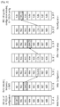
- FIG. 6 shows an example of scheduling DL messages according to an embodiment of the present invention.
- D-CSS NB is configured at DL subframe A.
- the UE may monitor the D-CSS to receive scheduling information for RAR at DL subframe B.
- D-CSS NB is configured at DL subframe A′.
- the UE may monitor the D-CSS to receive scheduling information for RRC message, which corresponds to initial and reconfiguration of UE-specific configuration including M-PDCCH configuration, at DL subframe B′.
- the UE may monitor USS at DL subframe C′.
- RAR/Msg4 corresponding to initial access (before configured with C-RNTI) or paging in RRC_IDLE or initial configuration of UE-specific configuration may be scheduled via D-CSS.
- the UE may expect to receive M-PDCCH scheduling RAR/Msg4 and RRC message from the same NB via CSS configured in that NB.
- CSS is configured in the UE-specific NB with USS, one of the following alternatives may be considered.
- FIG. 7 shows another example of scheduling DL messages according to an embodiment of the present invention.
- D-CSS NB is configured at DL subframe A.
- the UE may monitor the D-CSS to receive scheduling information for RAR at DL subframe B.
- D-CSS NB is configured at DL subframe A′.
- the UE may monitor the D-CSS to receive scheduling information for RRC message at DL subframe B′.
- the UE may monitor CSS/USS at DL subframe C′ in the UE-specific NB.
- CSS is configured at DL subframe E in that UE-specific NB.
- the UE may monitor CSS to receive scheduling information for RRC message at DL subframe F.
- CSS is configured at DL subframe E′ in that UE-specific NB.
- the UE may monitor CSS to receive scheduling information for RRC message at DL subframe F′.
- Option 3 Dedicated resource+CSS/USS in a UE-specific NB
- dedicated resource(s) is configured for channel/data transmission before a UE is configured with UE-specific NB.
- RAR may be transmitted via a dedicated resource and UE-specific configuration may be given by SIB or RAR or Msg4 (or a combination of those).
- Msg4 transmission one of the following alternatives may be considered.
- a UE is configured with UE-specific NB, similar to option 2 described above, CSS in the same NB may be used to schedule RAR/Msg4 and reconfiguration of RRC messages.
- FIG. 8 shows another example of scheduling DL messages according to an embodiment of the present invention.
- SIB for dedicated resource is configured at DL subframe A.
- the SIB may include a list of MPDCCH configurations.
- the UE may receive RAR indicating a temporary C-RNTI at DL subframe B, and the UE may monitor CSS/USS at DL subframe C in the UE-specific NB.
- CSS is configured at DL subframe E in that UE-specific NB.
- the UE may monitor CSS to receive scheduling information for RRC message at DL subframe F.
- CSS is configured at DL subframe E′ in that UE-specific NB.
- the UE may monitor CSS to receive scheduling information for RRC message at DL subframe F′.
- This option is similar to option 3, except that CSS is not defined in a UE-specific NB.
- RAR/paging may be transmitted from the dedicated resource which is configured for initial setup procedure even after the UE is configured with a UE-specific NB.
- RRC message of UE-specific reconfiguration may be scheduled via USS in the UE-specific NB.
- reconfiguration of repetition/CE level changes one of the following alternatives may be considered.
- FIG. 9 shows another example of scheduling DL messages according to an embodiment of the present invention.
- SIB for dedicated resource is configured at DL subframe A.
- the SIB may include a list of MPDCCH configurations.
- the UE may receive RAR indicating a temporary C-RNTI at DL subframe B, and the UE may monitor USS at DL subframe C in the UE-specific NB.
- USS is configured at DL subframe D in that UE-specific NB.
- the UE may monitor USS to receive scheduling information for RRC message at DL subframe E.
- D-CSS + No need of dedicated UE may need to retune to USS resource configuration D-CSS NB if TDM is used for cell broadcast Configuration of D-CSS transmissions such as may be necessary. paging/RAR/Msg4. In CE, overhead of M- PDCCH for cell-broadcast transmission may be inefficient.
- D-CSS + No need of dedicated Configuration of D-CSS CSS/USS in a UE- resource configuration may be necessary.
- specific NB for cell broadcast Configuration of CSS in a transmissions such as UE-specific NB may be paging/RAR/Msg4. necessary. No need of retuning to In CE, overhead of M- monitor CSS.
- PDCCH for cell-broadcast transmission may be inefficient.
- Option 3 Dedicated In CE, overhead of Flexibility in terms of resource + CSS/ M-PDCCH for cell- multiplexing multiple USS in a UE- broadcast transmission cell-broadcast transmissions specific NB may be reduced. may be limited. Reconfiguration of CE Initial configuration of UE- level change may be specific configuration may supported efficiently require considerable via CSS in a UE- specification impact. specific NB.
- Option 4 Dedicated In CE, overhead of Flexibility in terms of resource + USS in a M-PDCCH for cell- multiplexing multiple UE-specific NB broadcast transmission cell-broadcast transmissions can be reduced. may be limited. Initial configuration of UE- specific configuration may require considerable specification impact. Configuration of CE level seems not easily supported by this option.
- At least one of the followings may be required to be configured for configuration of D-CSS.
- USS may configured via RRC message scheduled by D-CSS.
- configuration of D-CSS may be the same as option 1 described above. Further, details of USS/CSS coexistence in a same NB may be addressed separately. Further, when CSS is configured, a default ACK/NACK resource may be configured separately.
- Option 3 dedicated resource for cell broadcast data may be required to be configured. Further, for initial reconfiguration, at least one of the following approaches may be considered.
- option 4 handling of RRC ambiguity may be needed.
- CE level may change where RRC message may not be received by the UE due to mismatch of CE level. For example, if a UE experiences a sudden CE level increase, this issue may arise. In this case, a UE may initiate PRACH again to setup the CE level.
- option 3/4 if NB location of M-PDCCH is changed, there may be the ambiguity issue.
- option 2 may be used where a UE reads D-CSS occasionally. In case the network needs to reconfigure NB location, the network may transmit RRC reconfiguration message via D-CSS.
- Another approach to handle the ambiguity is to transmit M-PDCCH in both NBs with different configuration until the network is assumed that the UE has received the RRC reconfiguration message. From a UE perspective, it applies the subband location change once it received reconfiguration message.
- ACK/NACK resource indicator offset may be reserved to indicate to use a dedicated ACK/NACK resource configured to a UE may be used instead of implicit resource.
- the network may dynamically indicate a fallback of ACK/NACK resource to the known ACK/NACK resource when ambiguity issue arises.
- Another option is to use ACK/NACK resource mapped to CSS which may also be directly indicated by DCI.
- option 2 or option 3 shows an example of resource indication/assignment.
- configuring/assigning NB(s) for each channel the following may be considered.
- a dedicated NB carrying CSS for RAR, paging and Msg4 temporary C-RNTI
- initial configuration of UE-specific configuration such as M-PDCCH configuration may be configured before USS is configured.
- NB used for PDSCH scheduled by DCI via this CSS may be indicated by DCI or semi-statically configured per repetition level used in DCI.
- the same NB may also be used for RAR, paging and Msg4 to minimize retuning to other NBs and service interruption time. The followings may be considered.
- FIG. 10 shows a method for receiving, by a UE, a downlink message according to an embodiment of the present invention. This embodiment may correspond to option 2 described above.
- step S 100 the UE receives scheduling information for a downlink message via a D-CSS in a first narrowband from a network.
- the UE may receive a configuration for the D-CSS from the network.
- the configuration may include at least one of a configuration of the first narrowband or a search space configuration.
- the UE receives the downlink message in the second narrowband from the network.
- the downlink message corresponds to one of a random access response for an initial access, a contention resolution message for the initial access, or a paging message.
- the downlink message corresponds to a RRC message for an initial configuration of a UE-specific configuration.
- the UE-specific configuration may include a configuration of an M-PDCCH, and the UE-specific configuration may configure a third narrowband for the M-PDCCH.
- the UE may further receive scheduling information for a reconfiguration of the UE-specific configuration via a CSS in the third narrowband from the network after the third narrowband is configured.
- the CSS and a USS may be configured in the third narrowband via TDM.
- a repetition level for the CSS may be higher than a repetition level for the USS.
- Both the CSS and the USS may be monitored in each starting subframe for the M-PDCCH.
- the CSS and the USS may have different starting subframe sets from each other.
- FIG. 11 shows a wireless communication system to implement an embodiment of the present invention.
- An eNB 800 may include a processor 810 , a memory 820 and a transceiver 830 .
- the processor 810 may be configured to implement proposed functions, procedures and/or methods described in this description. Layers of the radio interface protocol may be implemented in the processor 810 .
- the memory 820 is operatively coupled with the processor 810 and stores a variety of information to operate the processor 810 .
- the transceiver 830 is operatively coupled with the processor 810 , and transmits and/or receives a radio signal.
- a MTC UE 900 may include a processor 910 , a memory 920 and a transceiver 930 .
- the processor 910 may be configured to implement proposed functions, procedures and/or methods described in this description. Layers of the radio interface protocol may be implemented in the processor 910 .
- the memory 920 is operatively coupled with the processor 910 and stores a variety of information to operate the processor 910 .
- the transceiver 930 is operatively coupled with the processor 910 , and transmits and/or receives a radio signal.
- the processors 810 , 910 may include application-specific integrated circuit (ASIC), other chipset, logic circuit and/or data processing device.
- the memories 820 , 920 may include read-only memory (ROM), random access memory (RAM), flash memory, memory card, storage medium and/or other storage device.
- the transceivers 830 , 930 may include baseband circuitry to process radio frequency signals.
- the techniques described herein can be implemented with modules (e.g., procedures, functions, and so on) that perform the functions described herein.
- the modules can be stored in memories 820 , 920 and executed by processors 810 , 910 .
- the memories 820 , 920 can be implemented within the processors 810 , 910 or external to the processors 810 , 910 in which case those can be communicatively coupled to the processors 810 , 910 via various means as is known in the art.
Abstract
Description
-
- M-PDCCH may indicate the narrow-band where RAR PDSCH is scheduled.
- A dedicated narrow-band may be configured either by SIB or predefined, where RAR occasion is configured or implicitly determined based on PRACH configuration.
-
Center 6 PRBs may always be used for RAR transmission where RAR occasion may be determined based on RAR occasion configuration or based on PRACH configuration.
-
- CSS may be defined as a set of search space where non C-RNTI based RNTIs (such as P-RNTI, RA-RNTI, transmit power control RNTI (TPC-RNTI), etc.) may be read as well. Further, CSS and USS may also have different set of blind detection candidates in terms of repetition levels and/or aggregation levels. On the other hand, USS may be defined a set of search space where only C-RNTI (and also semi-persistent scheduling (SPS) C-RNTI, temporary C-RNTI) is monitored.
- CSS may be only differentiated from USS in terms of repetition level and/or aggregation level. In that sense, USS may also carry non C-RNTI based transmission for cell-common data. In other words, only CSS may be configured where two different sets of {repetition level, aggregation level} may be configured.
-
- Alt 1: A UE may always monitor both CSS and USS in each starting subframe for M-PDCCH. In this case, if high repetition level is assumed for CSS, a UE may always have to search high repetition level. To allow reconfiguration CE level change or common scheduling over different repetition levels, repetition level monitored for CSS may be higher than USS.
- Alt 2: CSS and USS may have different starting subframe sets. If this is used, the set of starting subframe for CSS may be more restricted compared to USS. Thus, it may restrict the possible occasion of M-PDCCH scheduling via CSS. For example, if enhanced PHICH (EPHICH) is used which is scheduled via CSS, this may restrict the occasion of EPHICH transmission.
-
- Alt 1: Dedicated resource may be used for initial Msg4 (based on temporary C-RNTI) and M-PDCCH may schedule after initial Msg4.
- Alt 2: M-PDCCH in USS may always schedule Msg4 assuming that temporary C-RNTI is equal to C-RNTI (this requires that M-PDCCH configuration is done before Msg4).
- Alt 3: Mini-CSS or dedicated control resource/region may be used for Msg4.
-
- Alt 1: A UE may monitor all repetition/CE levels such that reconfiguration of repetition/CE level of M-PDCCH is not required. This approach may be inefficient in terms of UE-power and complexity. Particularly for a UE with small repetition/CE level, this approach can be inefficient.
- Alt 2: Two different M-PDCCH set may be configured. Each M-PDCCH set may have different set of aggregation level(s) and/or repetition level(s) and individual starting subframe set.
| TABLE 1 | ||
| Benefits | Drawbacks | |
| Option 1: D-CSS + | No need of dedicated | UE may need to retune to |
| USS | resource configuration | D-CSS NB if TDM is used |
| for cell broadcast | Configuration of D-CSS | |
| transmissions such as | may be necessary. | |
| paging/RAR/Msg4. | In CE, overhead of M- | |
| PDCCH for cell-broadcast | ||
| transmission may be | ||
| inefficient. | ||
| Option 2: D-CSS + | No need of dedicated | Configuration of D-CSS |
| CSS/USS in a UE- | resource configuration | may be necessary. |
| specific NB | for cell broadcast | Configuration of CSS in a |
| transmissions such as | UE-specific NB may be | |
| paging/RAR/Msg4. | necessary. | |
| No need of retuning to | In CE, overhead of M- | |
| monitor CSS. | PDCCH for cell-broadcast | |
| transmission may be | ||
| inefficient. | ||
| Option 3: Dedicated | In CE, overhead of | Flexibility in terms of |
| resource + CSS/ | M-PDCCH for cell- | multiplexing multiple |
| USS in a UE- | broadcast transmission | cell-broadcast transmissions |
| specific NB | may be reduced. | may be limited. |
| Reconfiguration of CE | Initial configuration of UE- | |
| level change may be | specific configuration may | |
| supported efficiently | require considerable | |
| via CSS in a UE- | specification impact. | |
| specific NB. | ||
| Option 4: Dedicated | In CE, overhead of | Flexibility in terms of |
| resource + USS in a | M-PDCCH for cell- | multiplexing multiple |
| UE-specific NB | broadcast transmission | cell-broadcast transmissions |
| can be reduced. | may be limited. | |
| Initial configuration of UE- | ||
| specific configuration may | ||
| require considerable | ||
| specification impact. | ||
| Configuration of CE level | ||
| seems not easily supported | ||
| by this option. | ||
-
- NB of D-CSS: If dedicated, the first NB (virtually the first) may be used for D-CSS. Or, the next NB to SIB-1 NB may also be used for D-CSS.
- Search space configuration: For enhanced coverage and normal coverage, two sets of blind decoding candidate and/or search space may be needed. For normal coverage, enhanced PDCCH (EPDCCH) configuration for D-CSS may be necessary with a default demodulation reference signal (DM-RS) scrambling ID. For normal coverage, a set of aggregation levels, e.g. 8 or 16, may be configured or prefixed. For CE, a set of aggregation levels and/or a set of repetition levels that a UE shall monitor for CE mode may be configured or prefixed. One simple approach of repetition levels may be to fix to monitor all repetition levels where only one aggregation level which is determined by the number of PRBs configured for D-CSS is assumed. For example, if 6 PRBs is configured for D-CSS, 24 aggregation levels may be assumed. On the other hand, if 4 PRBs is configured for D-CSS, 16 aggregation levels may be assumed. In terms of PRBs for D-CSS, a default value may be 6 PRBs, though optionally the number of PRBs may be configured. In case of indication of 6 PRBs, instead of utilizing current mechanism of resource allocation, NB+{0, 1, 2} may be indicated, where 0 means 2 PRBs (starting from the lowest PRB), 1 means 4 PRBs (starting from the lowest PRB), and 2
means 6 PRBs. Additionally, 1 more state may be used to refer 2 PRBs starting from the lowest or highest PRB within a NB. - Default PUCCH offset: To support, e.g. ACK/NACK transmission, a default resource offset may be configured.
-
- SIB itself may contain the list of EPDCCH configurations. The EPDCCH configuration may be determined by C-RNTI % M, where M is the number of EPDCH configurations contained in SIB.
- SIB itself may contain scheduling information of PDSCH where actual configuration of list of EPDCCH configuration is transmitted. For CE support, the number of repetition in addition to starting subframe may be necessary. Also, separate configuration of this type of resource for normal coverage and CE may be further considered.
- RAR itself may contain the EPDCCH configuration which will be used once contention resolution is completed.
- RAR may include only occasion, transport block size (TBS), repetition number of PDSCH where EPDCCH configuration is transmitted.
- Msg4 itself may contain the EPDCCH configuration which will be used once contention resolution is completed.
- Msg4 may include only occasion, TBS, repetition number of PDSCH where EPDCCH configuration is transmitted.
- A set of dedicated resource may be configured which contains EPDCCH configurations only. For example, the set of dedicated resource may be K subframe after Msg4 transmission (initial Msg4). K may be prefixed or configured by the network. The repetition number used for EPDCCH configuration may be the maximum or prefixed or configured by the network per CE level used by PRACH. In other words, the number of repetition may be used for EPDCCH configuration after Msg4 can be derived from the CE level used by PRACH and/or higher layer configuration.
-
- SIB1: A dedicated NB may carry SIB1 which may be hopped if frequency hopping is enabled.
- PRACH resource configuration: At most one separate NB may be allocated per CE level. If the network supports 3 CE levels with normal coverage, total four NBs may be used for PRACH resources.
- RAR resource configuration: If RAR is scheduled with the associated M-PDCCH, in normal coverage, one NB for M-PDCCH for RAR may be configured. PDSCH may be scheduled in a different NB via DCI. In CE, one NB for PDSCH may be semi-statically configured per CE level used by PRACH. If RAR is scheduled without the associated MPDCCH, at most one NB may be allocated per CE level used by PRACH.
- Paging resource configuration for RRC_IDLE UEs: Depending on paging occasion, one or multiple NBs may be configured by the network. If paging is scheduled with the associated M-PDCCH, in normal coverage, one NB for M-PDCCH for paging may be configured. PDSCH may be scheduled in a different NB via DCI. In CE, one NB for PDSCH may be semi-statically configured per CE level used by PRACH. Otherwise, if multiple NBs are configured, NB may be determined by P-RNTI.
- Msg4 (temporary C-RNTI): If Msg4 is scheduled with the associated M-PDCCH, in normal coverage, one NB for M-PDCCH for Msg4 may be configured. PDSCH may be scheduled in a different NB via DCI. In CE, one NB for PDSCH may be semi-statically configured per CE level used by PRACH. If Msg4 is scheduled without the associated MPDCCH, at most one NB may be allocated per CE level used by PRACH.
-
- RAR: If PRACH is triggered by PDCCH order and RAR is scheduled with the associated M-PDCCH, NB for M-PDCCH may be the same as the NB of USS for the given UE. The same mechanism to determine a NB of PDSCH scheduled by USS may be used for PDSCH NB of RAR. Otherwise, the same resource as initial PRACH transmission may be monitored.
- Paging resource for RRC_CONNECTED UEs: If paging is scheduled with the associated M-PDCCH, the same NB as UE-specific NB may be used for paging as well. The same mechanism to determine a NB of PDSCH scheduled by USS may be used for PDSCH NB of paging. Otherwise, the same resource as initial PRACH transmission may be monitored.
- Msg4: If Msg4 is scheduled with C-RNTI and with the associated M-PDCCH, NB for M-PDCCH may be the same as the NB of USS for the given UE. The same mechanism to determine a NB of PDSCH scheduled by USS may be used for PDSCH NB of Msg4. Otherwise, the same resource as initial PRACH transmission may be monitored.
- RRC reconfiguration message: RRC reconfiguration message may be scheduled with the associated M-PDCCH. The NB of M-PDCCH may be same as the NB of USS, though it may use non-UE-specific SS.
- Multiple CSS NBs may be configured
- Different CSS NB may be monitored per purpose (e.g. different NB between paging and RAR)
- Same NB may be used for CSS and USS when a UE is connected.
Claims (2)
Priority Applications (1)
| Application Number | Priority Date | Filing Date | Title |
|---|---|---|---|
| US15/568,678 US10536895B2 (en) | 2015-05-13 | 2016-05-13 | Method and apparatus for performing initial access procedure for low cost user equipment in wireless communication system |
Applications Claiming Priority (3)
| Application Number | Priority Date | Filing Date | Title |
|---|---|---|---|
| US201562161214P | 2015-05-13 | 2015-05-13 | |
| US15/568,678 US10536895B2 (en) | 2015-05-13 | 2016-05-13 | Method and apparatus for performing initial access procedure for low cost user equipment in wireless communication system |
| PCT/KR2016/005099 WO2016182391A1 (en) | 2015-05-13 | 2016-05-13 | Method and apparatus for performing initial access procedure for low cost user equipment in wireless communication system |
Publications (2)
| Publication Number | Publication Date |
|---|---|
| US20180192354A1 US20180192354A1 (en) | 2018-07-05 |
| US10536895B2 true US10536895B2 (en) | 2020-01-14 |
Family
ID=57248235
Family Applications (1)
| Application Number | Title | Priority Date | Filing Date |
|---|---|---|---|
| US15/568,678 Active 2036-05-17 US10536895B2 (en) | 2015-05-13 | 2016-05-13 | Method and apparatus for performing initial access procedure for low cost user equipment in wireless communication system |
Country Status (2)
| Country | Link |
|---|---|
| US (1) | US10536895B2 (en) |
| WO (1) | WO2016182391A1 (en) |
Families Citing this family (22)
| Publication number | Priority date | Publication date | Assignee | Title |
|---|---|---|---|---|
| CN105099639B (en) * | 2015-05-15 | 2018-12-18 | 上海华为技术有限公司 | A kind of method, apparatus and communication node of control channel transmission |
| WO2016183768A1 (en) * | 2015-05-18 | 2016-11-24 | Mediatek Singapore Pte. Ltd. | Method and apparatus of enhanced paging |
| EP3332592B1 (en) * | 2015-08-06 | 2023-01-25 | Samsung Electronics Co., Ltd. | Method and apparatus for performing inter-carrier d2d communication |
| CN107852292B (en) * | 2015-08-12 | 2021-06-08 | 苹果公司 | Configuration of non-UE specific search spaces for M-PDCCH |
| US11496872B2 (en) | 2015-11-06 | 2022-11-08 | Qualcomm Incorporated | Search spaces and grants in eMTC |
| US10419192B2 (en) * | 2016-09-30 | 2019-09-17 | Motorola Mobility Llc | Method and apparatus for reporting channel state information |
| US11197251B2 (en) * | 2016-11-04 | 2021-12-07 | Qualcomm Incorporated | Techniques and apparatuses for synchronization, scheduling, bandwidth allocation, and reference signal transmission in a 5th generation network |
| CN108235435A (en) * | 2016-12-15 | 2018-06-29 | 华为技术有限公司 | A kind of resource indicating method and device |
| CN108260209B (en) * | 2016-12-28 | 2020-08-11 | 上海朗帛通信技术有限公司 | Method and device for UE (user equipment) and base station for random access |
| CN112073167B (en) * | 2017-01-06 | 2023-09-08 | 展讯通信(上海)有限公司 | Transmission method, receiving method, base station and user equipment of synchronous signal block |
| US11171820B2 (en) * | 2017-03-23 | 2021-11-09 | Convida Wireless, Llc | Terminal device, infrastructure equipment and methods |
| GB2560770A (en) | 2017-03-24 | 2018-09-26 | Nec Corp | Communication system |
| CN108809558B (en) * | 2017-04-28 | 2021-07-20 | 维沃移动通信有限公司 | Transmission method of synchronization signal block, network equipment and user equipment |
| US10897753B2 (en) * | 2017-05-04 | 2021-01-19 | Sharp Kabushiki Kaisha | Systems and methods for supporting multiple allocations in UL/DL grant for a 5G NR UE and gNB |
| ES2948850T3 (en) * | 2017-07-27 | 2023-09-20 | Ntt Docomo Inc | User terminal and radio communication method |
| MX2020002578A (en) * | 2017-09-11 | 2020-07-20 | Ntt Docomo Inc | User equipment and wireless communication method. |
| US11026215B2 (en) * | 2017-09-15 | 2021-06-01 | Apple Inc. | UE specific search space and a common search space in a wide coverage enhancement |
| KR20210040433A (en) | 2018-08-09 | 2021-04-13 | 지티이 코포레이션 | Pre-configured dedicated resource for idle mode transmission |
| WO2020097775A1 (en) * | 2018-11-12 | 2020-05-22 | Nokia Shanghai Bell Co., Ltd. | Communications with preconfigured uplink resources |
| CN111278149B (en) * | 2019-01-30 | 2022-02-08 | 维沃移动通信有限公司 | Information sending method, information detection method, terminal equipment and network equipment |
| US11265932B2 (en) * | 2019-01-30 | 2022-03-01 | Qualcomm Incorporated | Narrowband selection for measurement reporting in random access |
| CN113709894B (en) * | 2020-05-22 | 2024-01-26 | 大唐移动通信设备有限公司 | Search space configuration method and device |
Citations (5)
| Publication number | Priority date | Publication date | Assignee | Title |
|---|---|---|---|---|
| US20130083753A1 (en) * | 2011-09-30 | 2013-04-04 | Interdigital Patent Holdings, Inc. | Device communication using a reduced channel bandwidth |
| WO2013129883A1 (en) | 2012-02-29 | 2013-09-06 | 엘지전자 주식회사 | Method and apparatus for control information search in wireless communication system |
| US20140185540A1 (en) * | 2013-01-03 | 2014-07-03 | Qualcomm Incorporated | Enb pdcch implementation to avoid ambiguous dci information |
| US20140307560A1 (en) | 2011-11-01 | 2014-10-16 | Lg Electronics Inc. | Method and wireless device for monitoring control channel |
| US20160212664A1 (en) * | 2015-01-16 | 2016-07-21 | Sharp Kabushiki Kaisha | Wireless Terminals, Base Stations, Communication Systems, Communication Methods, and Integrated Circuits |
-
2016
- 2016-05-13 WO PCT/KR2016/005099 patent/WO2016182391A1/en active Application Filing
- 2016-05-13 US US15/568,678 patent/US10536895B2/en active Active
Patent Citations (5)
| Publication number | Priority date | Publication date | Assignee | Title |
|---|---|---|---|---|
| US20130083753A1 (en) * | 2011-09-30 | 2013-04-04 | Interdigital Patent Holdings, Inc. | Device communication using a reduced channel bandwidth |
| US20140307560A1 (en) | 2011-11-01 | 2014-10-16 | Lg Electronics Inc. | Method and wireless device for monitoring control channel |
| WO2013129883A1 (en) | 2012-02-29 | 2013-09-06 | 엘지전자 주식회사 | Method and apparatus for control information search in wireless communication system |
| US20140185540A1 (en) * | 2013-01-03 | 2014-07-03 | Qualcomm Incorporated | Enb pdcch implementation to avoid ambiguous dci information |
| US20160212664A1 (en) * | 2015-01-16 | 2016-07-21 | Sharp Kabushiki Kaisha | Wireless Terminals, Base Stations, Communication Systems, Communication Methods, and Integrated Circuits |
Non-Patent Citations (3)
| Title |
|---|
| Ericsson, "EPDCCH initialization and reconfiguration for MTC", R1-151213, 3GPP TSG RAN WG1 Meeting #80bis, Belgrade, Serbia, Apr. 20-24, 2015, 7 pgs. |
| NTT DOCOMO et al., "WF on UE-specific EPDCCH set initialization", R1-152346, 3GPP TSG RAN WG1 #80bis, Belgrade, Serbia, Apr. 20-24, 2015, 3 pgs. |
| NTT DOCOMO, "EPDCCH configuration for Rel-13 low complexity MTC", R1-152050, 3GPP TSG RAN WG1 Meeting #80bis, Belgrade, Serbia, Apr. 20-24, 2015, 5 pgs. |
Also Published As
| Publication number | Publication date |
|---|---|
| WO2016182391A1 (en) | 2016-11-17 |
| US20180192354A1 (en) | 2018-07-05 |
Similar Documents
| Publication | Publication Date | Title |
|---|---|---|
| US10536895B2 (en) | Method and apparatus for performing initial access procedure for low cost user equipment in wireless communication system | |
| US11411705B2 (en) | Method and apparatus for handling starting subframe of control channel for MTC UE in wireless communication system | |
| US10945195B2 (en) | Method and apparatus for configuring bandwidth including direct current subcarrier for low cost user equipment in wireless communication system | |
| US11706068B2 (en) | Method and apparatus for performing initial access procedure for low cost user equipment in wireless communication system | |
| US10615842B2 (en) | Method and apparatus for configuring frequency hopping pattern for MTC UE in wireless communication system | |
| US10673671B2 (en) | Method and apparatus for performing cell search in wireless communication system | |
| US11026112B2 (en) | Method and apparatus for performing measurement in an extension carrier | |
| US10868658B2 (en) | Method and apparatus for handling various IoT network access in wireless communication system | |
| US10587383B2 (en) | Method and apparatus for designing downlink control information in wireless communication system | |
| US10554249B2 (en) | Method and apparatus for handling frequency retuning for machine-type communication user equipment in wireless communication system | |
| US10326568B2 (en) | Method and apparatus for supporting frequency hopping for low cost user equipment in wireless communication system | |
| US10257807B2 (en) | Method and apparatus for supporting variable transport block size without associated downlink control information in wireless communication system | |
| US11330582B2 (en) | Method and apparatus for defining basic resource unit for NB-IOT user equipment in wireless communication system | |
| US10389489B2 (en) | Method and apparatus for configuring timing relationship between HARQ-ACK and PUSCH for MTC UE in wireless communication system |
Legal Events
| Date | Code | Title | Description |
|---|---|---|---|
| FEPP | Fee payment procedure |
Free format text: ENTITY STATUS SET TO UNDISCOUNTED (ORIGINAL EVENT CODE: BIG.); ENTITY STATUS OF PATENT OWNER: LARGE ENTITY |
|
| AS | Assignment |
Owner name: LG ELECTRONICS INC., KOREA, REPUBLIC OF Free format text: ASSIGNMENT OF ASSIGNORS INTEREST;ASSIGNORS:YI, YUNJUNG;YOU, HYANGSUN;SIGNING DATES FROM 20170712 TO 20170717;REEL/FRAME:043936/0843 |
|
| STPP | Information on status: patent application and granting procedure in general |
Free format text: RESPONSE TO NON-FINAL OFFICE ACTION ENTERED AND FORWARDED TO EXAMINER |
|
| STPP | Information on status: patent application and granting procedure in general |
Free format text: FINAL REJECTION MAILED |
|
| STPP | Information on status: patent application and granting procedure in general |
Free format text: DOCKETED NEW CASE - READY FOR EXAMINATION |
|
| STPP | Information on status: patent application and granting procedure in general |
Free format text: NOTICE OF ALLOWANCE MAILED -- APPLICATION RECEIVED IN OFFICE OF PUBLICATIONS |
|
| STPP | Information on status: patent application and granting procedure in general |
Free format text: AWAITING TC RESP., ISSUE FEE NOT PAID |
|
| STPP | Information on status: patent application and granting procedure in general |
Free format text: NOTICE OF ALLOWANCE MAILED -- APPLICATION RECEIVED IN OFFICE OF PUBLICATIONS |
|
| STPP | Information on status: patent application and granting procedure in general |
Free format text: PUBLICATIONS -- ISSUE FEE PAYMENT VERIFIED |
|
| STCF | Information on status: patent grant |
Free format text: PATENTED CASE |
|
| MAFP | Maintenance fee payment |
Free format text: PAYMENT OF MAINTENANCE FEE, 4TH YEAR, LARGE ENTITY (ORIGINAL EVENT CODE: M1551); ENTITY STATUS OF PATENT OWNER: LARGE ENTITY Year of fee payment: 4 |