EP3748874B1 - Unterwassernetzwerkvorrichtung - Google Patents
Unterwassernetzwerkvorrichtung Download PDFInfo
- Publication number
- EP3748874B1 EP3748874B1 EP18931525.2A EP18931525A EP3748874B1 EP 3748874 B1 EP3748874 B1 EP 3748874B1 EP 18931525 A EP18931525 A EP 18931525A EP 3748874 B1 EP3748874 B1 EP 3748874B1
- Authority
- EP
- European Patent Office
- Prior art keywords
- cpl
- primary
- cpls
- output
- tertiary
- Prior art date
- Legal status (The legal status is an assumption and is not a legal conclusion. Google has not performed a legal analysis and makes no representation as to the accuracy of the status listed.)
- Active
Links
Images







Classifications
-
- H—ELECTRICITY
- H04—ELECTRIC COMMUNICATION TECHNIQUE
- H04B—TRANSMISSION
- H04B10/00—Transmission systems employing electromagnetic waves other than radio-waves, e.g. infrared, visible or ultraviolet light, or employing corpuscular radiation, e.g. quantum communication
- H04B10/29—Repeaters
- H04B10/291—Repeaters in which processing or amplification is carried out without conversion of the main signal from optical form
-
- H—ELECTRICITY
- H01—ELECTRIC ELEMENTS
- H01S—DEVICES USING THE PROCESS OF LIGHT AMPLIFICATION BY STIMULATED EMISSION OF RADIATION [LASER] TO AMPLIFY OR GENERATE LIGHT; DEVICES USING STIMULATED EMISSION OF ELECTROMAGNETIC RADIATION IN WAVE RANGES OTHER THAN OPTICAL
- H01S3/00—Lasers, i.e. devices using stimulated emission of electromagnetic radiation in the infrared, visible or ultraviolet wave range
- H01S3/05—Construction or shape of optical resonators; Accommodation of active medium therein; Shape of active medium
- H01S3/06—Construction or shape of active medium
- H01S3/063—Waveguide lasers, i.e. whereby the dimensions of the waveguide are of the order of the light wavelength
- H01S3/067—Fibre lasers
- H01S3/06708—Constructional details of the fibre, e.g. compositions, cross-section, shape or tapering
- H01S3/06716—Fibre compositions or doping with active elements
-
- H—ELECTRICITY
- H01—ELECTRIC ELEMENTS
- H01S—DEVICES USING THE PROCESS OF LIGHT AMPLIFICATION BY STIMULATED EMISSION OF RADIATION [LASER] TO AMPLIFY OR GENERATE LIGHT; DEVICES USING STIMULATED EMISSION OF ELECTROMAGNETIC RADIATION IN WAVE RANGES OTHER THAN OPTICAL
- H01S3/00—Lasers, i.e. devices using stimulated emission of electromagnetic radiation in the infrared, visible or ultraviolet wave range
- H01S3/05—Construction or shape of optical resonators; Accommodation of active medium therein; Shape of active medium
- H01S3/06—Construction or shape of active medium
- H01S3/063—Waveguide lasers, i.e. whereby the dimensions of the waveguide are of the order of the light wavelength
- H01S3/067—Fibre lasers
- H01S3/06708—Constructional details of the fibre, e.g. compositions, cross-section, shape or tapering
- H01S3/06729—Peculiar transverse fibre profile
- H01S3/06737—Fibre having multiple non-coaxial cores, e.g. multiple active cores or separate cores for pump and gain
-
- H—ELECTRICITY
- H01—ELECTRIC ELEMENTS
- H01S—DEVICES USING THE PROCESS OF LIGHT AMPLIFICATION BY STIMULATED EMISSION OF RADIATION [LASER] TO AMPLIFY OR GENERATE LIGHT; DEVICES USING STIMULATED EMISSION OF ELECTROMAGNETIC RADIATION IN WAVE RANGES OTHER THAN OPTICAL
- H01S3/00—Lasers, i.e. devices using stimulated emission of electromagnetic radiation in the infrared, visible or ultraviolet wave range
- H01S3/05—Construction or shape of optical resonators; Accommodation of active medium therein; Shape of active medium
- H01S3/06—Construction or shape of active medium
- H01S3/063—Waveguide lasers, i.e. whereby the dimensions of the waveguide are of the order of the light wavelength
- H01S3/067—Fibre lasers
- H01S3/06754—Fibre amplifiers
-
- H—ELECTRICITY
- H01—ELECTRIC ELEMENTS
- H01S—DEVICES USING THE PROCESS OF LIGHT AMPLIFICATION BY STIMULATED EMISSION OF RADIATION [LASER] TO AMPLIFY OR GENERATE LIGHT; DEVICES USING STIMULATED EMISSION OF ELECTROMAGNETIC RADIATION IN WAVE RANGES OTHER THAN OPTICAL
- H01S3/00—Lasers, i.e. devices using stimulated emission of electromagnetic radiation in the infrared, visible or ultraviolet wave range
- H01S3/09—Processes or apparatus for excitation, e.g. pumping
- H01S3/091—Processes or apparatus for excitation, e.g. pumping using optical pumping
- H01S3/094—Processes or apparatus for excitation, e.g. pumping using optical pumping by coherent light
- H01S3/094003—Processes or apparatus for excitation, e.g. pumping using optical pumping by coherent light the pumped medium being a fibre
- H01S3/094011—Processes or apparatus for excitation, e.g. pumping using optical pumping by coherent light the pumped medium being a fibre with bidirectional pumping, i.e. with injection of the pump light from both two ends of the fibre
-
- H—ELECTRICITY
- H01—ELECTRIC ELEMENTS
- H01S—DEVICES USING THE PROCESS OF LIGHT AMPLIFICATION BY STIMULATED EMISSION OF RADIATION [LASER] TO AMPLIFY OR GENERATE LIGHT; DEVICES USING STIMULATED EMISSION OF ELECTROMAGNETIC RADIATION IN WAVE RANGES OTHER THAN OPTICAL
- H01S3/00—Lasers, i.e. devices using stimulated emission of electromagnetic radiation in the infrared, visible or ultraviolet wave range
- H01S3/09—Processes or apparatus for excitation, e.g. pumping
- H01S3/091—Processes or apparatus for excitation, e.g. pumping using optical pumping
- H01S3/094—Processes or apparatus for excitation, e.g. pumping using optical pumping by coherent light
- H01S3/094049—Guiding of the pump light
- H01S3/094053—Fibre coupled pump, e.g. delivering pump light using a fibre or a fibre bundle
-
- H—ELECTRICITY
- H01—ELECTRIC ELEMENTS
- H01S—DEVICES USING THE PROCESS OF LIGHT AMPLIFICATION BY STIMULATED EMISSION OF RADIATION [LASER] TO AMPLIFY OR GENERATE LIGHT; DEVICES USING STIMULATED EMISSION OF ELECTROMAGNETIC RADIATION IN WAVE RANGES OTHER THAN OPTICAL
- H01S3/00—Lasers, i.e. devices using stimulated emission of electromagnetic radiation in the infrared, visible or ultraviolet wave range
- H01S3/09—Processes or apparatus for excitation, e.g. pumping
- H01S3/091—Processes or apparatus for excitation, e.g. pumping using optical pumping
- H01S3/094—Processes or apparatus for excitation, e.g. pumping using optical pumping by coherent light
- H01S3/094061—Shared pump, i.e. pump light of a single pump source is used to pump plural gain media in parallel
-
- H—ELECTRICITY
- H01—ELECTRIC ELEMENTS
- H01S—DEVICES USING THE PROCESS OF LIGHT AMPLIFICATION BY STIMULATED EMISSION OF RADIATION [LASER] TO AMPLIFY OR GENERATE LIGHT; DEVICES USING STIMULATED EMISSION OF ELECTROMAGNETIC RADIATION IN WAVE RANGES OTHER THAN OPTICAL
- H01S3/00—Lasers, i.e. devices using stimulated emission of electromagnetic radiation in the infrared, visible or ultraviolet wave range
- H01S3/09—Processes or apparatus for excitation, e.g. pumping
- H01S3/091—Processes or apparatus for excitation, e.g. pumping using optical pumping
- H01S3/094—Processes or apparatus for excitation, e.g. pumping using optical pumping by coherent light
- H01S3/09408—Pump redundancy
-
- H—ELECTRICITY
- H04—ELECTRIC COMMUNICATION TECHNIQUE
- H04B—TRANSMISSION
- H04B10/00—Transmission systems employing electromagnetic waves other than radio-waves, e.g. infrared, visible or ultraviolet light, or employing corpuscular radiation, e.g. quantum communication
- H04B10/29—Repeaters
-
- H—ELECTRICITY
- H01—ELECTRIC ELEMENTS
- H01S—DEVICES USING THE PROCESS OF LIGHT AMPLIFICATION BY STIMULATED EMISSION OF RADIATION [LASER] TO AMPLIFY OR GENERATE LIGHT; DEVICES USING STIMULATED EMISSION OF ELECTROMAGNETIC RADIATION IN WAVE RANGES OTHER THAN OPTICAL
- H01S3/00—Lasers, i.e. devices using stimulated emission of electromagnetic radiation in the infrared, visible or ultraviolet wave range
- H01S3/14—Lasers, i.e. devices using stimulated emission of electromagnetic radiation in the infrared, visible or ultraviolet wave range characterised by the material used as the active medium
- H01S3/16—Solid materials
- H01S3/1601—Solid materials characterised by an active (lasing) ion
- H01S3/1603—Solid materials characterised by an active (lasing) ion rare earth
- H01S3/1608—Solid materials characterised by an active (lasing) ion rare earth erbium
-
- H—ELECTRICITY
- H01—ELECTRIC ELEMENTS
- H01S—DEVICES USING THE PROCESS OF LIGHT AMPLIFICATION BY STIMULATED EMISSION OF RADIATION [LASER] TO AMPLIFY OR GENERATE LIGHT; DEVICES USING STIMULATED EMISSION OF ELECTROMAGNETIC RADIATION IN WAVE RANGES OTHER THAN OPTICAL
- H01S3/00—Lasers, i.e. devices using stimulated emission of electromagnetic radiation in the infrared, visible or ultraviolet wave range
- H01S3/23—Arrangements of two or more lasers not provided for in groups H01S3/02 - H01S3/22, e.g. tandem arrangements of separate active media
- H01S3/2383—Parallel arrangements
-
- H—ELECTRICITY
- H04—ELECTRIC COMMUNICATION TECHNIQUE
- H04B—TRANSMISSION
- H04B10/00—Transmission systems employing electromagnetic waves other than radio-waves, e.g. infrared, visible or ultraviolet light, or employing corpuscular radiation, e.g. quantum communication
- H04B10/29—Repeaters
- H04B10/291—Repeaters in which processing or amplification is carried out without conversion of the main signal from optical form
- H04B10/2912—Repeaters in which processing or amplification is carried out without conversion of the main signal from optical form characterised by the medium used for amplification or processing
-
- H—ELECTRICITY
- H04—ELECTRIC COMMUNICATION TECHNIQUE
- H04B—TRANSMISSION
- H04B10/00—Transmission systems employing electromagnetic waves other than radio-waves, e.g. infrared, visible or ultraviolet light, or employing corpuscular radiation, e.g. quantum communication
- H04B10/29—Repeaters
- H04B10/291—Repeaters in which processing or amplification is carried out without conversion of the main signal from optical form
- H04B10/293—Signal power control
Definitions
- the present invention relates to the field of submarine optical cable communications, and in particular, to a submarine network device.
- a long distance submarine fiber optical cable communication system (generally a link over 500 km) needs to be equipped with a submarine optical repeater so as to realize the amplification of the optical signal transmitted.
- the currently mature submarine optical repeaters are based on erbium doped fiber amplifier (EDFA) technology.
- EDFA erbium doped fiber amplifier
- the gain medium of EDFA is erbium-doped fiber, and during the normal working of an EDFA, a pump laser is required for providing excitation energy to the erbium doped fiber.
- the rest pump lasers that work normally can still provide a part of the energy to the two lines of erbium doped fiber, so that the two lines of EDFA modules can still maintain a certain amplification function.
- the number of the pump lasers is twice as many as the number of EDFA modules. Because each fiber pair corresponds to 2 EDFA modules, each time a fiber pair is added, the number of the pump lasers needs to be multiplied, which may cause a high cost, a high power consumption and a high heat consumption.
- the embodiments of the present invention provide a submarine network device, which lowers the cost, the power consumption and the heat consumption of the submarine network device.
- a submarine network device which includes a fiber set, a pump laser set, an EDFA set, a primary fiber coupler (CPL) set and a secondary CPL set
- the primary CPL set includes N primary CPLs
- the secondary CPL set includes N secondary CPLs, with N being an integer greater than or equal to 3
- the fiber set is configured to connect the pump laser set, the primary CPL set, the secondary CPL set and the EDFA set
- an input port of each primary CPL in the primary CPL set is at least connected with a pump laser
- an output port of each secondary CPL in the secondary CPL set is at least connected with an EDFA
- each primary CPL in the primary CPL set is adjacent to the other two primary CPLs in the primary CPL set
- each secondary CPL in the secondary CPL set is adjacent to the other two secondary CPLs in the secondary CPL set
- output ports of each primary CPL in the primary CPL set are respectively connected with two different secondary C
- Each pump laser in the pump laser set is configured to emit pumping laser
- each primary CPL in the primary CPL set is configured for couple the received pumping laser and output two lines of primary pumping laser.
- the two lines of primary pumping laser are respectively output to two different secondary CPLs
- each secondary CPL in the secondary CPL set is configured to couple the received primary pumping laser and output at least one line of secondary pumping laser to at least one EDFA.
- the pumping laser energy of each line of EDFA is jointly provided by at least two pump lasers. Even if a part of the pump laser corresponding to each line of EDFA fails to work, the EDFA module can still maintain a certain amplification function. On this basis, because the input port of each primary CPL is connected with at least one pump laser, the output port of each secondary CPL is connected with at least one EDFA, and the number of the pump lasers does not need to be maintained as twice of that of the EDFA module. Therefore, the cost, the power consumption and the heat consumption of the submarine network device may be lowered.
- each EDFA in the EDFA set corresponds to one optical fiber
- the output port of each secondary CPL in the secondary CPL set is connected with two EDFAs.
- the two optical fibers corresponding to the two EDFAs connected with the output port of each secondary CPL form a fiber pair.
- one optical fiber corresponding to one of the EDFAs connected with the output port of each secondary CPL and one optical fiber corresponding to one of the EDFAs connected with the output port of one secondary CPL adjacent to each secondary CPL form a fiber pair.
- a fiber pair refers to two optical fibers connected with the receiving port and the sending port of a line transmission equipment (LTE).
- LTE line transmission equipment
- the two optical fibers form a communication link with one line for receiving and the other line for sending, and different fiber pairs are isolated from each other.
- each primary CPL in the primary CPL set is connected with one pump laser
- each line of primary pumping laser output by each primary CPL includes 50% of the energy respectively emitted by one pump laser connected with the input port of each primary CPL
- each line of secondary pumping laser output by each secondary CPL in the secondary CPL set includes 25% of the energy respectively emitted by two pump lasers connected with the input ports of two primary CPLs
- each secondary CPL is connected with two primary CPLs.
- each primary CPL in the primary CPL set is connected with four pump lasers
- each line of primary pumping laser output by each primary CPL includes 50% of the energy respectively emitted by four pump lasers connected with the input port of each primary CPL
- each line of secondary pumping laser output by each secondary CPL in the secondary CPL set includes 25% of the energy respectively emitted by eight pump lasers connected with the input ports of two primary CPLs
- each secondary CPL is connected with two primary CPLs.
- each primary CPL is connected with one or four pump lasers, thereby improving the flexibility of the solution.
- the pump laser set, the EDFA set, the primary CPL set and the secondary CPL set are separately disposed in different planes.
- different types of components in the submarine network device are separately disposed on different planes, so that there is a larger space for wiring between different types of components.
- each pump laser in the pump laser set, each EDFA in the EDFA set, each primary CPL in the primary CPL set and each secondary CPL in the secondary CPL set are arranged annually.
- each component in the submarine network device is arranged annually, a complete closed loop may be formed, and it has a structural symmetry. Moreover, unlimited expansion is supported on this basis.
- a submarine network device which includes a fiber set, a pump laser set, an EDFA set, a primary fiber coupler (CPL) set, a secondary CPL set and a tertiary CPL set, wherein the primary CPL set includes N primary CPLs, the secondary CPL set includes N secondary CPLs, and the tertiary CPL set includes N tertiary CPLs, with N being an integer greater than or equal to 5, and the fiber set is configured to connect the pump laser set, the primary CPL set, the secondary CPL set, the tertiary CPL set and the EDFA set, an input port of each primary CPL in the primary CPL set is at least connected with a pump laser, an output port of each tertiary CPL in the tertiary CPL set is at least connected with an EDFA, each primary CPL in the primary CPL set is adjacent to the other two primary CPLs in the primary CPL set, each secondary fiber coupler (CPL) set, a secondary CPL set and
- Each pump laser in the pump laser set is configured to emit pumping laser
- each primary CPL in the primary CPL set is configured for couple the received pumping laser and output two lines of primary pumping laser, and the two lines of primary pumping laser are respectively output to the two different secondary CPLs connected with the output port of each primary CPL
- each secondary CPL in the secondary CPL set is configured to couple the received primary pumping laser and output two lines of secondary pumping laser to two different tertiary CPLs
- each tertiary CPL in the tertiary CPL set is configured to couple the received secondary pumping laser and output at least one line of tertiary pumping laser to at least one EDFA.
- the pumping laser energy of each line of EDFA is jointly provided by at least four pump lasers corresponding thereto. Even if a part of the pump laser corresponding to each line of EDFA fails, the EDFA module can still maintain a certain amplification function.
- the number of the pump lasers is not always more than that of EDFA modules. Therefore, the number of the pump lasers used is small, and the cost, and the power consumption and the heat consumption of the submarine network device are lowered.
- each EDFA in the EDFA set corresponds to one optical fiber
- output ports of each tertiary CPL in the tertiary CPL set are connected with two EDFAs.
- the two optical fibers corresponding to the two EDFAs connected with the output port of each tertiary CPL form a fiber pair.
- one optical fiber corresponding to one of the EDFAs connected with the output port of each tertiary CPL and one optical fiber corresponding to one of the EDFAs connected with the output port of a tertiary CPL adjacent to each tertiary CPL form a fiber pair.
- each primary CPL in the primary CPL set is connected with two pump lasers
- each line of primary pumping laser output by each primary CPL includes 50% of the energy respectively emitted by the two pump lasers connected with the input port of each primary CPL
- each line of secondary pumping laser output by each secondary CPL in the secondary CPL set includes 25% of the energy respectively emitted by the four pump lasers connected with the input ports of two primary CPLs
- each secondary CPL is connected with two primary CPLs
- each line of tertiary pumping laser output by each tertiary CPL in the tertiary CPL set includes 12.5% of the energy respectively emitted by eight pump lasers connected with the input ports of four primary CPLs
- each tertiary CPL is connected with two secondary CPLs
- the two secondary CPLs are connected with four primary CPLs.
- the pumping laser energy of each line of EDFA is jointly provided by eight pump lasers corresponding thereto, and each pump laser contributes 12.5% of the energy.
- each pump laser contributes 12.5% of the energy.
- the number of the pump lasers is the same as that of the EDFAs, thus the number of the pump lasers used is small, the cost is low, the overall power consumption is small, and the overall heat consumption is small.
- each primary CPL in the primary CPL set is connected with one pump laser
- each line of primary pumping laser output by each primary CPL includes 50% of the energy respectively emitted by one pump laser connected with the input port of each primary CPL
- each line of secondary pumping laser output by each secondary CPL in the secondary CPL set includes 25% of the energy respectively emitted by two pump lasers connected with the input ports of two primary CPLs
- each secondary CPL is connected with two primary CPLs
- each line of tertiary pumping laser output by each tertiary CPL in the tertiary CPL set includes 12.5% of the energy respectively emitted by four pump lasers connected with the input ports of four primary CPLs
- each tertiary CPL is connected with two secondary CPLs
- the two secondary CPLs are connected with four primary CPLs.
- each primary CPL in the primary CPL set is connected with four pump lasers
- each line of primary pumping laser output by each primary CPL includes 50% of the energy respectively emitted by four pump lasers connected with the input port of each primary CPL
- each line of secondary pumping laser output by each secondary CPL in the secondary CPL set includes 25% of the energy respectively emitted by the eight pump lasers connected with the input ports of two primary CPLs
- each secondary CPL is connected with two primary CPLs
- each line of tertiary pumping laser output by each tertiary CPL in the tertiary CPL set includes 12.5% of the energy respectively emitted by sixteen pump lasers connected with the input ports of four primary CPLs
- each tertiary CPL is connected with two secondary CPLs
- the two secondary CPLs are connected with four primary CPLs.
- each primary CPL is connected with one or four pump lasers, thereby improving the flexibility of the solution.
- different types of components in the submarine network device are separately disposed on different planes, so that there is a larger space for wiring between different types of components.
- each pump laser in the pump laser set, each EDFA in the EDFA set, each primary CPL in the primary CPL set , each secondary CPL in the secondary CPL set and each tertiary CPL in the tertiary CPL set are arranged annually.
- each component in the submarine network device is arranged annually, a complete closed loop may be formed, and it has a structural symmetry. Moreover, unlimited expansion is supported on this basis.
- a submarine network device which includes a pump laser set, an EDFA set, a primary fiber coupler (CPL) set and a secondary CPL set, wherein the primary CPL set at least includes three CPL primary CPLs, the secondary CPL set at least includes three secondary CPLs, and an input port of each primary CPL in the primary CPL set is at least connected with a pump laser, an output port of each secondary CPL in the secondary CPL set is connected with at least one EDFA in the EDFA set, output ports of at least one primary CPL in the primary CPL set are respectively connected with two different secondary CPLs that are spaced by a secondary CPL, and input ports of at least one secondary CPL in the secondary CPL set are respectively connected with two different primary CPLs that are spaced by a primary CPL.
- CPL primary fiber coupler
- Each pump laser in the pump laser set is configured to emit pumping laser
- at least one primary CPL in the primary CPL set is configured to couple the received pumping laser and output two lines of primary pumping laser, the two lines of primary pumping laser being respectively output to the two different secondary CPLs
- at least one secondary CPL in the secondary CPL set is configured to couple the received primary pumping laser and output at least one line of secondary pumping laser to the at least one EDFA.
- the pumping laser energy of each line of EDFA is jointly provided by at least two pump lasers. Even if a part of the pump laser corresponding to each line of EDFA fails, the EDFA module can still maintain a certain amplification function. On this basis, because the input port of each primary CPL is connected with at least one pump laser, the output port of each secondary CPL is connected with at least one EDFA, and the number of the pump lasers does not need to be maintained as twice of that of the EDFA module, thus the cost, the power consumption and the heat consumption of the submarine network device may be lowered.
- each EDFA in the EDFA set corresponds to one optical fiber
- the output port of each secondary CPL in the secondary CPL set is connected with two EDFAs.
- the two optical fibers corresponding to the two EDFAs connected with the output port of each secondary CPL form a fiber pair.
- one optical fiber corresponding to one of the EDFAs connected with the output port of each secondary CPL and one optical fiber corresponding to one of the EDFAs connected with the output port of one secondary CPL adjacent to each secondary CPL form a fiber pair.
- the embodiments of the invention provide a submarine network device, thereby lowering the cost, the power consumption and the heat consumption of the submarine network device.
- the invention may be applied to the field of submarine fiber optical cable communications.
- the submarine network device in the invention may specifically be a submarine optical repeater.
- a long distance submarine fiber optical cable communication system (generally a link over 500 km) needs to be equipped with a submarine optical repeater to realize the amplification of an optical signal transmitted.
- the submarine optical repeater needs to operate underwater for a long period of time, and it is required to guarantee a design lifetime of 25 years. Because a construction craft is required in the maintenance of an underwater device of the submarine cable system and underwater maintenance has the features of high difficulty, long cycle and high cost, etc., underwater optical repeater needs to have high reliability so as to lower the risk of failure and maintenance.
- the submarine optical repeater in the invention is based on EDFA technology.
- the gain medium of EDFA is erbium-doped fiber.
- a pump laser is required to provide excitation energy to the erbium-doped fiber.
- the pumping laser emitted by the pump laser and a signal light are coupled into the same fiber and fed into an erbium-doped fiber via a wavelength division multiplexer.
- the pump laser belongs to active optical apparatus, and the failure rate thereof is high relative to other inactive optical apparatus.
- the failure of the pump laser will cause the optical repeater unable to work normally, thus a pump redundant design is often required to improve the overall reliability of the optical repeater.
- the existing pump redundant solution mainly includes a single fiber 2 ⁇ 1 architecture, a single fiber pair 2 ⁇ 2 architecture and a single fiber pair 4 ⁇ 2 architecture.
- FIG. 2 shows the pump redundant design solution of single fiber 2 ⁇ 1 architecture (2 pump laser ⁇ 1 optical fiber).
- the pumping laser output by the two pump lasers is input into the erbium-doped fiber on one optical fiber, that is, two pump lasers jointly support one line of EDFA module.
- the pump laser fails, a half of the pump power can be input into the erbium-doped fiber, so that the EDFA module can still maintain a certain amplification function.
- the system reliability is low, when the two pump lasers supporting the same fiber fail at the same time, the EDFA module on the fiber will be unable to work, and thus system service interruption will be caused. Additionally, the number of the pump lasers is twice that of the EDFA modules, thus the cost is high, and the power consumption and the heat consumption are large.
- FIG. 3 shows a pump redundant design solution of a single fiber pair 2 ⁇ 2 architecture (2 pump lasers ⁇ 2 optical fibers), wherein two pump lasers jointly support a pair (two lines) of EDFA modules.
- the two lines of pumping laser output by the two pump lasers are coupled by the fiber coupler, the light power thereof is redistributed, so that each pump laser respectively provides a half of the pumping energy to each of the two lines of erbium-doped fiber.
- the other pump laser can still provide energy to the two lines of erbium-doped fiber, so that the two lines of EDFA modules can still maintain a certain amplification function.
- FIG. 4 shows another pump redundant design solution of single fiber pair 2 ⁇ 2 architecture (2 pump lasers ⁇ 2 optical fibers), wherein the pumping laser output by each pump laser is split by a fiber splitter into two lines of sub-pumping laser. Then, the sub-pumping laser from one pump laser and the sub-pumping laser from the other pump laser are coupled by a fiber coupler together to provide pumping energy for a line of erbium-doped fiber. When one pump laser fails, the other pump laser can still provide energy to the two lines of erbium-doped fiber, so that the two lines of EDFA modules can still maintain a certain amplification function.
- FIG. 5 shows another pump redundant design solution of a single fiber pair 2 ⁇ 2 architecture (2 pump lasers ⁇ 2 optical fibers).
- the first pumping laser is divided into a first sub-pumping laser and a second sub-pumping laser that are respectively input into the erbium-doped fiber in the two optical fibers.
- the second pumping laser is divided into a third sub-pumping laser and fourth sub-pumping laser that are respectively input into the erbium-doped fiber in the two optical fibers.
- the other pump laser can still provide energy to the two lines of erbium-doped fiber, so that the two lines of EDFA modules can still maintain a certain amplification function.
- the invention provides a novel pump redundant design solution, by which pump sharing between any fiber pair in a multi-fiber pair application scene can be realized.
- each line of EDFA may simultaneously have the pumping light input from 4 pump lasers, and 4 ⁇ 4 pump redundant may be realized.
- FIG. 6 is a three-dimensional structure diagram of a submarine optical repeater according to one embodiment of the invention, wherein, the apparatus the submarine optical repeater includes: a fiber, a pump laser, an EDFA, a primary CPL and a secondary CPL.
- the invention is mainly applied to a multi-fiber pair scene, generally, for distinguishing from the prior-art solution, at least a 3-fiber pair (six optical fibers) application scene, the number of the above pump lasers, primary CPLs and secondary CPLs is no less than 3, and the number of the above EDFAs should correspond to that of the fiber pairs, that is, each optical fiber should correspondingly have one EDFA, thus the number of EDFAs is no less than 6.
- the above primary CPL and secondary CPL may be CPLs of the same structure, and it is only distinguished from the functions in this solution.
- the primary CPL and the secondary CPL in the invention may be a CPL that includes 2 input ports and 2 output ports and has a port loss of 3 dB.
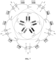
- FIG. 7 is an unfolded plan view of the above FIG. 6 .
- the pump laser, the EDFA, the primary CPL and the secondary CPL are separately disposed in different planes.
- each pump laser, each EDFA, each primary CPL and each secondary CPL are arranged annually to form a closed structure.
- the input port of each primary CPL is at least connected with a pump laser (for example, as shown in FIG. 6 or FIG. 7 , the input port of each primary CPL may be connected with two pump lasers), and the output port of each secondary CPL is connected with two EDFAs.
- Each primary CPL in the primary CPL set is adjacent to the other 2 primary CPLs in the primary CPL set, and each secondary CPL in the secondary CPL set is adjacent to the other 2 secondary CPLs in the secondary CPL set.
- the output port of the primary CPL is cross-connected with the input port of the secondary CPL via a fiber, the two different the secondary CPLs connected with each primary CPL are spaced by a secondary CPL, and the two different primary CPLs connected with each secondary CPL are spaced by a primary CPL.
- each primary CPL has a secondary CPL arranged symmetrically thereto, that is, the primary CPL and the secondary CPL may be on the same axis, and the axis is respectively vertical to the plane on which each primary CPL and each secondary CPL exists.
- the pump laser is configured to emit pumping laser.
- the primary CPL is configured to couple the received pumping laser and outputting two lines of primary pumping laser, and the two lines of primary pumping laser are respectively output to two different secondary CPLs. Because the output port of the primary CPL is cross-connected with the input port of the secondary CPL via a fiber, the two secondary CPLs are spaced by another secondary CPL.
- the secondary CPL is configured to couple the received primary pumping laser and output two lines of secondary pumping laser to two different EDFAs.
- each of the above apparatus is connected via a fiber.
- the EDFA includes an input port, an output port and a pump power input terminal, wherein signal light is input from the input port of the EDFA via a fiber, the secondary pumping laser output by the secondary CPL is input into the EDFA from the pump power input terminal, and the optical signal processed by the EDFA is output from the output port of the EDFA via the fiber.
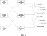
- the arbitrary three primary CPLs are respectively a first primary CPL, a second primary CPL and a third primary CPL
- the three secondary CPLs arranged symmetrically thereto are respectively a first secondary CPL, a second secondary CPL and a third secondary CPL, wherein the second primary CPL is respectively adjacent to the first primary CPL and the third primary CPL, and the second secondary CPL is respectively adjacent to the first secondary CPL and the third secondary CPL.
- the output port of the first primary CPL is connected with the input port of the second secondary CPL
- the output port of the second primary CPL is connected with the input port of the first secondary CPL
- the output port of the second primary CPL is connected with the input port of the third secondary CPL
- the output port of the third primary CPL is connected with the input port of the second secondary CPL.
- the output port of the first secondary CPL is connected with the pump power input terminal of the first EDFA
- the output port of the second secondary CPL is connected with the pump power input terminal of the second EDFA
- the output port of the second secondary CPL is connected with the pump power input terminal of the third EDFA
- the output port of the third secondary CPL is connected with the pump power input terminal of the fourth EDFA.
- the submarine optical repeater does not necessarily has the cylinder structure shown in FIG. 5 , and there may be other external structures packaging each of the above internal apparatus, for example, it may be a cuboid structure, which is not limited here.
- FIG. 9 is a side exploded view of the above FIG. 6 , and it corresponds to the structure of a submarine optical repeater in a 5-fiber pair application scene according to an embodiment of the invention, which includes: 10 pump lasers (P01 to P10), 5 primary CPLs (CPL1-1 to CPL1-5), 5 secondary CPLs (CPL2-1 to CPL2-5) and 10 EDFA modules (A01 to A10).
- the input port of CPL1-1 is connected with P01 and P02
- the input port of CPL1-2 of CPL1-2 is connected with P03 and P04
- the input port of CPL1-3 is connected with P05 and P06
- the input port of CPL1-4 is connected with P07 and P08
- the input port of CPL1-5 is connected with P09 and P10.
- the connection mode between the primary CPL and the secondary CPL is specifically as follows: the output port of CPL1-1 is respectively connected to the input port of CPL2-2 and the input port of CPL2-5, the output port of CPL1-2 is respectively connected to the input port of CPL2-1 and the input port of CPL2-3, the output port of CPL1-3 is respectively connected to the input port of CPL2-2 and the input port of CPL2-4, the output port of CPL1-4 is respectively connected to the input port of CPL2-3 and the input port of CPL2-5, and the output port of CPL1-5 is respectively connected to the input port of CPL2-1 and the input port of CPL2-4.
- each secondary CPL is connected with 2 EDFAs. Specifically, the output port of CPL2-1 is connected with A01 and A10, the output port of CPL2-2 is connected with A02 and A03, the output port of CPL2-3 is connected with A04 and A05, the output port of CPL2-4 is connected with A06 and A07, and the output port of CPL2-5 is connected with A08 and A09.
- each EDFA corresponds to one optical fiber
- the fiber is connected with the input port and the output port of the EDFA.
- 2 different secondary CPLs are connected with two optical fibers corresponding to the 2 EDFAs to form a fiber pair.
- the fibers corresponding to A01 and A02 form a fiber pair FP1
- the fibers corresponding to A03 and A04 form a fiber pair FP2
- the fibers corresponding to A05 and A06 form a fiber pair FP3
- the fibers corresponding to A07 and A08 form a fiber pair FP4
- the fibers corresponding to A09 and A10 form a fiber pair FP5.
- each line of primary pumping laser includes 50% of the energy of each of the group of (2) pump lasers.
- the pumping light of P01 and P02 is input to CPL1-1, and then CPL1-1 respectively outputs 50% of the energy of each of P01 and P02 to CPL2-2 and CPL2-5. That is, CPL1-1 receives 100% of the energy of P01 and 100% of the energy of P02, CPL2-2 receives 50% of the energy of P01 and 50% of the energy of P02, and CPL2-5 also receives 50% of the energy of P01 and 50% of the energy of P02.
- the primary pumping laser output by 2 different primary CPLs is coupled by the secondary CPL, the secondary CPL outputs 2 lines of secondary pumping laser.
- Each line of secondary pumping laser provides energy to 1 EDFA, and each line of secondary pumping laser includes 25% of the energy of each of the 4 pump lasers.
- CPL2-1 receives 2 lines of primary pumping laser output by CPL1-2 and CPL1-5. That is, CPL2-1 receives 50% of the energy of each of P03, P04, P09 and P10.
- CPL2-1 outputs 2 lines of secondary pumping laser respectively to A01 and A10, and each line of secondary pumping laser includes 25% of the energy of each of P03, P04, P09 and P10.
- the two lines of primary pumping laser output by each primary CPL and the two lines of secondary pumping laser output by each secondary CPL are both coupled in a ratio of 1:1.
- the ratio of the two lines of pumping laser output may also be adjusted according to different requirements, which is not limited here. For example, the pumping light of P01 and P02 is input to CPL1-1, then CPL1-1 outputs 30% of the energy of P01 and 70% of the energy of P02 to CPL2-2, and CPL1-1 outputs 70% of the energy of P01 and 30% of the energy of P02 to CPL2-5.
- the pumping laser energy of each line of EDFA is jointly provided by four pump lasers corresponding thereto, and each pump laser contributes 25% of the energy.
- each pump laser contributes 25% of the energy.
- the number of the pump lasers is the same as that of the EDFAs, thus the number of the pump lasers used is small, the cost is low, the overall power consumption is small, and the overall heat consumption is small. Additionally, it may be judged which group of pump lasers operates abnormally by detecting the variation of the output power of EDFA, which may be helpful to the maintenance of the system.
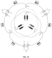
- FIG. 10 corresponds to a structure of a submarine optical repeater in a 3-fiber pair application scene according to an embodiment of the invention.
- the submarine optical repeater includes: 6 pump lasers (P01 to P06), 3 primary CPLs (CPL 1-1 to CPL1-3), 3 the secondary CPLs (CPL2-1 to CPL2-3) and 6 EDFA modules (A01 to A06).
- connection mode between the primary CPL and the secondary CPL is specifically as follows: the output port of CPL1-1 is respectively connected to the input port of CPL2-2 and the input port of CPL2-3, the output port of CPL1-2 is respectively connected to the input port of CPL2-1 and the input port of CPL2-3, and the output port of CPL1-3 is respectively connected to the input port of CPL2-1 and the input port of CPL2-2.
- each secondary CPL is connected with 2 EDFAs. Specifically, the output port of CPL2-1 is connected with A01 and A06, the output port of CPL2-2 is connected with A02 and A03, and the output port of CPL2-3 is connected with A04 and A05.
- each EDFA corresponds to one optical fiber
- the fiber is connected with the input port and the output port of the EDFA
- 2 different secondary CPLs are connected with two optical fibers corresponding to the 2 EDFAs to form a fiber pairs.
- the fibers corresponding to A01 and A02 form a fiber pair FP1
- the fibers corresponding to A03 and A04 form a fiber pair FP2
- the fibers corresponding to A05 and A06 form a fiber pair FP3.
- each line of primary pumping laser includes 50% of the energy of each of the group of (2) pump lasers.
- the pumping light of P01 and P02 is input to CPL1-1, and then the CPL1 -1 respectively outputs 50% of the energy of each of P01 and P02 to CPL2-2 and CPL2-3. That is, CPL1-1 receives 100% of the energy of P01 and 100% of the energy of P02, CPL2-2 receives 50% of the energy of P01 and 50% of the energy of P02, and CPL2-3 also receives 50% of the energy of P01 and 50% of the energy of P02.
- the primary pumping laser output by 2 different primary CPLs is coupled by the secondary CPL, the secondary CPL outputs 2 lines of secondary pumping laser, each line of secondary pumping laser provides energy to 1 EDFA, and each line of secondary pumping laser includes 25% of the energy of each of the 4 pump lasers.
- CPL2-1 receives 2 lines of primary pumping laser output by CPL1 -2 and CPL1-3, that is, CPL2-1 receives 50% of the energy of each of P03, P04, P05 and P06, CPL2-1 respectively outputs 2 lines of secondary pumping laser to A01 and A06, and each line of secondary pumping laser includes 25% of the energy of each of P03, P04, P05 and P06.
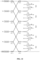
- FIG. 11 corresponds to a structure of a submarine optical repeater in an 8-fiber pair application scene according to an embodiment of the invention.
- the submarine optical repeater includes: 16 pump lasers (P01 to P16), 8 primary CPLs (CPL1-1 to CPL1-8), 8 secondary CPLs (CPL2-1 to CPL2-8) and 16 EDFA modules (A01 toA16).
- the input port of CPL1-1 is connected with P01 and P02
- the input port of CPL1-2 of CPL1-2 is connected with P03 and P04
- the input port of CPL1-3 is connected with P05 and P06
- the input port of CPL1-4 is connected with P07 and P08
- the input port of CPL1-5 is connected with P09 and P10
- the input port of CPL1-6 is connected with P11 and P12
- the input port of CPL1-7 is connected with P13 and P14
- the input port of CPL1-8 is connected with P15 and P16.
- the connection mode between the primary CPL and the secondary CPL is specifically as follows: the output port of CPL1-1 is respectively connected to the input port of CPL2-2 and the input port of CPL2-8, the output port of CPL1-2 is respectively connected to the input port of CPL2-1 and the input port of CPL2-3, the output port of CPL1-3 is respectively connected to the input port of CPL2-2 and the input port of CPL2-4, the output port of CPL1-4 is respectively connected to the input port of CPL2-3 and the input port of CPL2-5, the output port of CPL1-5 is respectively connected to the input port of CPL2-4 and the input port of CPL2-6, the output port of CPL1-6 is respectively connected to the input port of CPL2-5 and the input port of CPL2-7, the output port of CPL1-7 is respectively connected to the input port of CPL2-6 and the input port of CPL2-8, and the output port of CPL1-8 is respectively connected to the input port of CPL2-7 and the input port of CPL2-1.
- each secondary CPL is connected with 2 EDFAs. Specifically, the output port of CPL2-1 is connected with A01 and A16, the output port of CPL2-2 is connected with A02 and A03, the output port of CPL2-3 is connected with A04 and A05, the output port of CPL2-4 is connected with A06 and A07, the output port of CPL2-5 is connected with A08 and A09, the output port of CPL2-6 is connected with A10 and A11, the output port of CPL2-7 is connected with A12 and A13, and the output port of CPL2-8 is connected with A14 and A15.
- each EDFA corresponds to one optical fiber, and the fiber is connected with the input port and the output port of the EDFA, 2 different secondary CPLs are connected with two optical fibers corresponding to the 2 EDFAs to form a fiber pairs.
- each line of primary pumping laser includes 50% of the energy of each of the group of (2) pump lasers.
- the pumping light of P01 and P02 is input to CPL1-1, and then CPL1-1 respectively outputs 50% of the energy of each of P01 and P02 to CPL2-2 and CPL2-8. That is, CPL1-1 receives 100% of the energy of P01 and 100% of the energy of P02, CPL2-2 receives 50% of the energy of P01 and 50% of the energy of P02, and CPL2-8 also receives 50% of the energy of P01 and 50% of the energy of P02.
- the primary pumping laser output by 2 different primary CPLs is coupled by the secondary CPL, the secondary CPL outputs 2 lines of secondary pumping laser, each line of secondary pumping laser provides energy to 1 EDFA, and each line of secondary pumping laser includes 25% of the energy of each of the 4 pump lasers.
- CPL2-1 receives 2 lines of primary pumping laser output by CPL1 -2 and CPL1-8, that is, CPL2-1 receives 50% of the energy of each of P03, P04, P15 and P16, CPL2-1 respectively outputs 2 lines of secondary pumping laser to A01 and A16, and each line of secondary pumping laser includes 25% of the energy of each of P03, P04, P15 and P16.
- the two lines of primary pumping laser output by each primary CPL and the two lines of secondary pumping laser output by each secondary CPL are both coupled in a ratio of 1:1.
- the ratio of the two lines of pumping laser output may also be adjusted according to different requirements, which is not limited here. For example, the pumping light of P01 and P02 is input to CPL1-1, then CPL1-1 outputs 30% of the energy of P01 and 70% of the energy of P02 to CPL2-2, and CPL1-1 outputs 70% of the energy of P01 and 30% of the energy of P02 to CPL2-5.
- FIG. 9 to FIG. 11 all describe the scenes in which 2 different secondary CPLs are connected with two optical fibers corresponding to the 2 EDFAs to form a fiber pairs, and additionally, this solution may also be a scene in which the same secondary CPL is connected with two optical fibers corresponding to the 2 EDFAs to form a fiber pairs.
- the structure of such a submarine optical repeater will be introduced below still by an example of 5-fiber pair application scene.
- the submarine optical repeater includes: 10 pump lasers (P01 to P10), 5 primary CPLs (CPL1-1 to CPL1-5), 5 secondary CPLs (CPL2-1 to CPL2-5) and 10 EDFA modules (A01 to A10).
- the input port of CPL1-1 is connected with P01 and P02
- the input port of CPL1-2 of CPL1-2 is connected with P03 and P04
- the input port of CPL1-3 is connected with P05 and P06
- the input port of CPL1-4 is connected with P07 and P08
- the input port of CPL1-5 is connected with P09 and P10.
- the connection mode between the primary CPL and the secondary CPL is specifically as follows: the output port of CPL1-1 is respectively connected to the input port of CPL2-2 and the input port of CPL2-5, the output port of CPL1-2 is respectively connected to the input port of CPL2-1 and the input port of CPL2-3, the output port of CPL1-3 is respectively connected to the input port of CPL2-2 and the input port of CPL2-4, the output port of CPL1-4 is respectively connected to the input port of CPL2-3 and the input port of CPL2-5, and the output port of CPL1-5 is respectively connected to the input port of CPL2-1 and the input port of CPL2-4.
- each secondary CPL is connected with 2 EDFAs.
- the output port of CPL2-1 is connected with A01 and A02
- the output port of CPL2-2 is connected with A03 and A04
- the output port of CPL2-3 is connected with A05 and A06
- the output port of CPL2-4 is connected with A07 and A08
- the output port of CPL2-5 is connected with A09 and A10; wherein the fibers corresponding to A01 and A02 form a fiber pair FP1, the fibers corresponding to A03 and A04 form a fiber pair FP2, the fibers corresponding to A05 and A06 form a fiber pair FP3, the fibers corresponding to A07 and A08 form a fiber pair FP4, and the fibers corresponding to A09 and A10 form a fiber pair FP5.
- the fibers corresponding to two EDFAs connected with each secondary CPL form a fiber pairs, which is different from the solutions of the embodiments shown in FIG. 9 to FIG. 11 .
- each primary CPL is connected with two pump lasers. Additionally, the input port of each primary CPL may also be connected with other number of pump lasers, which will be described in detail below.
- FIG. 13 also shows a structure of a submarine optical repeater in a 5-fiber pair application scene according to an embodiment of the invention.
- the submarine optical repeater includes: 5 pump lasers (P01 to P05), 5 primary CPLs (CPL1-1 to CPL1-5), 5 secondary CPLs (CPL2-1 to CPL2-5) and 10 EDFA modules (A01 to A10).
- This embodiment differs from the embodiment of FIG. 9 in that the input port of each primary CPL is connected with one pump laser. Specifically, the input port of CPL1-1 is connected with P01, the input port of CPL1-2 is connected with P02, the input port of CPL1-3 is connected with P03, the input port of CPL1-4 is connected with P04, and the input port of CPL1-5 is connected with P05.
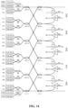
- FIG. 14 also shows a structure of a submarine optical repeater in a 5-fiber pair application scene according to an embodiment of the invention.
- the submarine optical repeater includes: 20 pump lasers (P01 to P20), 5 primary CPLs (CPL 1-1 to CPL1-5), 5 secondary CPLs (CPL2-1 to CPL2-5), 10 EDFA modules (A01 to A10) and 10 polarization beam combiners (PBCs).
- Each primary CPL may receive the energy provided by 4 pump lasers.
- every 2 pump lasers form a group, the output port of each group of pump lasers is connected to the input port of 1 PBC, and the input port of each primary CPL is connected with 2 different PBCs, wherein the PBC may combine two beams of polarized light orthogonal in the polarization direction into one beam.
- the PBC may combine the pumping light output by two pump lasers P01 and P02 into one beam and output it to CPL1-1, while the other PBC may combine the pumping light output by two pump lasers P03 and P04 into one beam and similarly output it to CPL1-1.
- the CPL in the submarine optical repeater described in the above embodiments is divided into a primary CPL and a secondary CPL. Additionally, in this solution, a tertiary CPL may further be added on this basis, which will be described in detail below.
- FIG. 15 shows a structure of a submarine optical repeater in a 10-fiber pair application scene according to an embodiment of the invention.
- the submarine optical repeater includes: 20 pump lasers (P01 to P20), 10 primary CPLs (CPL1-1 to CPL1-10), 10 secondary CPLs (CPL2-1 to CPL2-10), 10 tertiary CPLs (CPL3-1 to CPL3-10) and 20 EDFA modules (A01 to A20).
- the pump laser, the EDFA, the primary CPL, the secondary CPL and the tertiary CPL are separately disposed in different planes. Moreover, each pump laser, each EDFA, each primary CPL, each secondary CPL and each tertiary CPL are arranged annually to form a closed structure.
- the input port of each primary CPL is at least connected with a pump laser (for example, as shown in FIG. 15 , the input port of each primary CPL may be connected with two pump lasers), and the output port of each tertiary CPL is connected with two EDFAs.
- Each primary CPL in the primary CPL set is adjacent to the other 2 primary CPLs in the primary CPL set, each secondary CPL in the secondary CPL set is adjacent to the other 2 secondary CPLs in the secondary CPL set, and each tertiary CPL in the tertiary CPL set is adjacent to the other 2 tertiary CPLs in the tertiary CPL set.
- the output port of the primary CPL is cross-connected with the input port of the secondary CPL via a fiber, and the two secondary CPLs connected with each primary CPL are spaced by the other 2 secondary CPLs. For example, as shown in FIG.
- the output port of CPL1-1 is connected with CPL2-2 and CPL2-9, while CPL2-2 and CPL2-9 are spaced by CPL2-1 and CPL2-10.
- the output port of the secondary CPL is similarly cross-connected with the input port of the tertiary CPL via a fiber, and the two tertiary CPLs connected with each secondary CPL are spaced by another tertiary CPL.
- the output port of CPL2-1 is connected with CPL3-2 and CPL3-10, while CPL3-2 and CPL3-10 are spaced by one CPL3-1.
- the pump laser is configured to emit pumping laser.
- the primary CPL is configured to couple the received pumping laser and output two lines of primary pumping laser, and the two lines of primary pumping laser output are respectively output to two different secondary CPLs.
- the secondary CPL is configured to couple the received primary pumping laser and output two lines of secondary pumping laser to two different tertiary CPLs.
- the tertiary CPL is configured to couple the received secondary pumping laser and output two lines of tertiary pumping laser to two different EDFAs.
- the input port of CPL1-1 is connected with P01 and P02
- the input port of CPL1-2 of CPL1-2 is connected with P03 and P04
- the input port of CPL1-3 is connected with P05 and P06
- the input port of CPL1-4 is connected with P07 and P08
- the input port of CPL1-5 is connected with P09 and P10
- the input port of CPL1-6 is connected with P11 and P12
- the input port of CPL1-7 is connected with P13 and P14
- the input port of CPL1-8 is connected with P15 and P16
- the input port of CPL1-9 is connected with P17
- the input port of CPL1-10 is connected with P19 and P20.
- the connection mode between the primary CPL and the secondary CPL is specifically as follows: the output port of CPL1-1 is respectively connected to the input port of CPL2-2 and the input port of CPL2-9, the output port of CPL1-2 is respectively connected to the input port of CPL2-3 and the input port of CPL2-10, the output port of CPL1-3 is respectively connected to the input port of CPL2-1 and the input port of CPL2-4, the output port of CPL1-4 is respectively connected to the input port of CPL2-2 and the input port of CPL2-5, the output port of CPL1-5 is respectively connected to the input port of CPL2-3 and the input port of CPL2-6, the output port of CPL1-6 is respectively connected to the input port of CPL2-4 and the input port of CPL2-7, the output port of CPL1-7 is respectively connected to the input port of CPL2-5 and the input port of CPL2-8, the output port of CPL1-8 is respectively connected to the input port of CPL2-6 and the input port of CPL2-9, the output port of CPL1
- the connection mode between the secondary CPL and the tertiary CPL is specifically as follows: the output port of CPL2-1 is respectively connected to the input port of CPL3-2 and the input port of CPL3-10, the output port of CPL2-2 is respectively connected to the input port of CPL3-1 and the input port of CPL3-3, the output port of CPL2-3 is respectively connected to the input port of CPL3-2 and the input port of CPL3-4, the output port of CPL2-4 is respectively connected to the input port of CPL3-3 and the input port of CPL3-5, the output port of CPL2-5 is respectively connected to the input port of CPL3-4 and the input port of CPL3-6, the output port of CPL2-6 is respectively connected to the input port of CPL3-5 and the input port of CPL3-7, the output port of CPL2-7 is respectively connected to the input port of CPL3-6 and the input port of CPL3-8, the output port of CPL2-8 is respectively connected to the input port of CPL3-7 and the input port of CPL3-9, the
- each tertiary CPL is connected with 2 EDFAs.
- the output port of CPL3-1 is connected with A01 and A20
- the output port of CPL3-2 is connected with A02 and A03
- the output port of CPL3-3 is connected with A04 and A05
- the output port of CPL3-4 is connected with A06 and A07
- the output port of CPL3-5 is connected with A08 and A09
- the output port of CPL3-6 is connected with A10 and A11
- the output port of CPL3-7 is connected with A12 and A13
- the output port of CPL3-8 is connected with A14 and A15
- the output port of CPL3-9 is connected with A16 and A17
- the output port of CPL3-10 is connected with A18 and A19.
- each EDFA corresponds to one optical fiber
- the fiber is connected with the input port and the output port of the EDFA
- 2 different tertiary CPLs are connected with two optical fibers corresponding to the 2 EDFAs to form a fiber pairs.
- the fibers corresponding to A01 and A02 form a fiber pair FP1
- the fibers corresponding to A03 and A04 form a fiber pair FP2
- the fibers corresponding to A05 and A06 form a fiber pair FP3
- the fibers corresponding to A07 and A08 form a fiber pair FP4
- the fibers corresponding to A09 and A10 form a fiber pair FP5
- the fibers corresponding to A11 and A12 form a fiber pair FP6
- the fibers corresponding to A13 and A14 form a fiber pair FP7
- the fibers corresponding to A15 and A16 form a fiber pair FP8
- the fibers corresponding to A17 and A18 form a fiber pair FP9
- the fibers corresponding to A19 and A20 form a fiber pair FP10.
- each line of primary pumping laser includes 50% of the energy of each of the group of (2) pump lasers.
- the pumping light of P01 and P02 is input to CPL1-1, and then CPL1-1 respectively outputs 50% of the energy of each of P01 and P02 to CPL2-2 and CPL2-9. That is, CPL1-1 receives 100% of the energy of P01 and 100% of the energy of P02, CPL2-2 receives 50% of the energy of P01 and 50% of the energy of P02, and CPL2-9 also receives 50% of the energy of P01 and 50% of the energy of P02.
- the primary pumping laser output by 2 different primary CPLs is coupled by the secondary CPL, the secondary CPL outputs 2 lines of secondary pumping laser, and each line of secondary pumping laser includes 25% of the energy of each of the 4 pump lasers.
- CPL2-1 receives 2 lines of primary pumping laser output by CPL1-3 and CPL1-10, that is, CPL2-1 receives 50% of the energy of each of P05, P06, P19 and P20
- CPL2-1 respectively outputs 2 lines of secondary pumping laser to CPL3-2 and CPL3-10
- each line of secondary pumping laser includes 25% of the energy of each of P05, P06, P19 and P20.
- the secondary pumping laser output by 2 different secondary CPLs is coupled by a tertiary CPL, and the tertiary CPL outputs 2 lines of tertiary pumping laser, each line of tertiary pumping laser includes 12.5% of the energy of each of the 8 pump lasers.
- CPL3-1 receives 2 lines of secondary pumping laser output by CPL2-2 and CPL2-10
- CPL2-2 receives 2 lines of primary pumping laser output by CPL1-1 and CPL1-4
- CPL2-10 receives 2 lines of primary pumping laser output by CPL1-2 and CPL1-9
- CPL1-1 is connected with P01 and P02
- CPL1-4 is connected with P07 and P08
- CPL1-2 is connected with P03 and P04
- CPL1-9 is connected with P17 and P18.
- CPL3-1 outputs two lines of tertiary pumping laser to A01 and A20, wherein each line of tertiary pumping laser includes 12.5% of the energy of each of the 8 pump lasers of P01, P02, P03, P04, P07, P08, P17 and P18.
- the ratio of the two lines of pumping laser output by each level of CPL may also be adjusted according to different requirements, which is not limited here.
- the pumping light of P01 and P02 is input to CPL1-1, then CPL1-1 outputs 30% of the energy of P01 and 70% of the energy of P02 to CPL2-2, and the CPL1-1 outputs 70% of the energy of P01 and 30% of the energy of P02 to CPL2-9.
- the same tertiary CPL may also be connected with two optical fibers corresponding to the 2 EDFAs to form a fiber pairs.
- the input port of each primary CPL may also be connected with other number of pump lasers.
- the input port of each primary CPL is connected with 1 or 4 pump lasers, which is not limited here.
- the pumping laser energy of each line of EDFA is jointly provided by 8 pump lasers corresponding thereto, and each pump laser contributes 12.5% of the energy.
- each pump laser contributes 12.5% of the energy.
- the number of the pump lasers is the same as that of the EDFAs, thus the number of the pump lasers used is small, the cost is low, the overall power consumption is small, and the overall heat consumption is small. Additionally, it may be judged which group of pump lasers operates abnormally by detecting the variation of the output power of EDFA, which may be helpful to the maintenance of the system.
Landscapes
- Physics & Mathematics (AREA)
- Electromagnetism (AREA)
- Engineering & Computer Science (AREA)
- Plasma & Fusion (AREA)
- Optics & Photonics (AREA)
- Computer Networks & Wireless Communication (AREA)
- Signal Processing (AREA)
- Optical Communication System (AREA)
- Lasers (AREA)
Claims (15)
- Unterseenetzwerkvorrichtung, umfassend einen Fasersatz, einen Pumpenlasersatz (P01, ..., P10), einen Satz aus erbiumdotiertem Faserverstärker, nachfolgend hierin EDFA, (A01, ..., A10), dadurch gekennzeichnet, dass sie einen Satz aus primärem Faserkoppler, nachfolgend hierin CPL (CPL1-1, ..., CPL1-5) und einen sekundären CPL-Satz (CPL2-1, ..., CPL2-5) umfasst, wobei der primäre CPL-Satz N primäre CPLs umfasst, der sekundäre CPL-Satz N sekundäre CPLs umfasst, wobei N eine ganze Zahl größer als oder gleich 3 ist, der Fasersatz dazu ausgestaltet ist, den Pumpenlasersatz, den primären CPL-Satz, den sekundären CPL-Satz und den EDFA-Satz zu verbinden und ein Eingangsanschluss jedes primären CPL in dem primären CPL-Satz zumindest mit einem Pumpenlaser verbunden ist, ein Ausgangsanschluss jedes sekundären CPL in dem sekundären CPL-Satz zumindest mit einem EDFA verbunden ist, jeder primäre CPL in dem primären CPL-Satz benachbart zu den anderen zwei primären CPLs in dem primären CPL-Satz ist, jeder sekundäre CPL in dem sekundären CPL-Satz benachbart zu den anderen zwei sekundären CPLs in dem sekundären CPL-Satz ist, Ausgangsanschlüsse jedes primären CPL in dem primären CPL-Satz jeweils mit zwei verschiedenen sekundären CPLs verbunden sind, die durch einen sekundären CPL beabstandet sind, und Eingangsanschlüsse jedes sekundären CPL in dem sekundären CPL-Satz jeweils mit zwei verschiedenen primären CPLs verbunden sind, die durch einen primären CPL beabstandet sind,
jeder Pumpenlaser in dem Pumpenlasersatz dazu ausgestaltet ist, Pumpenlaser zu emittieren, jeder primäre CPL in dem primären CPL-Satz dazu ausgestaltet ist, den empfangenen Pumpenlaser zu koppeln und zwei Linien von primärem Pumpenlaser auszugeben, wobei die zwei Linien von primärem Pumpenlaser jeweils an die zwei verschiedenen sekundären CPLs ausgegeben werden, und jeder sekundäre CPL in dem sekundären CPL-Satz dazu ausgestaltet ist, den empfangenen primären Pumpenlaser zu koppeln und zumindest eine Linie von sekundärem Pumpenlaser an den zumindest einen EDFA auszugeben. - Unterseenetzwerkvorrichtung nach Anspruch 1, dadurch gekennzeichnet, dass jeder EDFA in dem EDFA-Satz einer optischen Faser entspricht und der Ausgangsanschluss jedes sekundären CPL in dem sekundären CPL-Satz mit zwei EDFAs verbunden ist.
- Unterseenetzwerkvorrichtung nach Anspruch 2, dadurch gekennzeichnet, dass die zwei optischen Fasern, die den zwei EDFAs entsprechen, die mit dem Ausgangsanschluss jedes sekundären CPL verbunden sind, ein Faserpaar bilden.
- Unterseenetzwerkvorrichtung nach Anspruch 2, dadurch gekennzeichnet, dass eine optische Faser, die einem der EDFAs entspricht, der mit dem Ausgangsanschluss jedes sekundären CPL verbunden ist, und eine optische Faser, die einem der EDFAs entspricht, der mit dem Ausgangsanschluss eines sekundären CPL benachbart zu dem jeden sekundären CPL verbunden ist, ein Faserpaar bilden.
- Unterseenetzwerkvorrichtung nach einem der Ansprüche 1 bis 4, dadurch gekennzeichnet, dass der Eingangsanschluss jedes primären CPL in dem primären CPL-Satz mit zwei Pumpenlasern verbunden ist, jede Linie an primärem Pumpenlaser ausgegeben durch jeden primären CPL 50 % der Energie umfasst, die jeweils durch die zwei Pumpenlaser emittiert wird, die mit dem Eingangsanschluss jedes primären CPL verbunden sind, jede Linie von sekundärem Pumpenlaser ausgegeben durch jeden sekundären CPL in dem sekundären CPL-Satz 25 % der Energie umfasst, die jeweils durch die vier Pumpenlaser emittiert wird, die mit den Eingangsanschlüssen von zwei primären CPLs verbunden sind, und jeder sekundäre CPL mit den zwei primären CPLs verbunden ist.
- Unterseenetzwerkvorrichtung nach einem der Ansprüche 1 bis 4, dadurch gekennzeichnet, dass der Eingangsanschluss jedes primären CPL in dem primären CPL-Satz mit einem Pumpenlaser verbunden ist, jede Linie an primärem Pumpenlaser ausgegeben durch jeden primären CPL 50 % der Energie umfasst, die jeweils durch einen Pumpenlaser emittiert wird, der mit dem Eingangsanschluss jedes primären CPL verbunden ist, jede Linie von sekundärem Pumpenlaser ausgegeben durch jeden sekundären CPL in dem sekundären CPL-Satz 25 % der Energie umfasst, die jeweils durch zwei Pumpenlaser emittiert wird, die mit den Eingangsanschlüssen von zwei primären CPLs verbunden sind, und jeder sekundäre CPL mit den zwei primären CPLs verbunden ist.
- Unterseenetzwerkvorrichtung nach einem der Ansprüche 1 bis 4, dadurch gekennzeichnet, dass der Eingangsanschluss jedes primären CPL in dem primären CPL-Satz mit vier Pumpenlasern verbunden ist, jede Linie an primärem Pumpenlaser ausgegeben durch jeden primären CPL 50 % der Energie umfasst, die jeweils durch die vier Pumpenlaser emittiert wird, die mit dem Eingangsanschluss jedes primären CPL verbunden sind, jede Linie von sekundärem Pumpenlaser ausgegeben durch jeden sekundären CPL in dem sekundären CPL-Satz 25 % der Energie umfasst, die jeweils durch acht Pumpenlaser emittiert wird, die mit den Eingangsanschlüssen von zwei primären CPLs verbunden sind, und jeder sekundäre CPL mit den zwei primären CPLs verbunden ist.
- Unterseenetzwerkvorrichtung nach einem der Ansprüche 1 bis 4, dadurch gekennzeichnet, dass der Pumpenlasersatz, der EDFA-Satz, der primäre CPL-Satz und der sekundäre CPL-Satz separat in verschiedenen Ebenen vorgesehen sind.
- Unterseenetzwerkvorrichtung nach einem der Ansprüche 1 bis 4, dadurch gekennzeichnet, dass jeder Pumpenlaser in dem Pumpenlasersatz, jeder EDFA in dem EDFA-Satz, jeder primäre CPL in dem primären CPL-Satz und jeder sekundäre CPL in dem sekundären CPL-Satz ringförmig angeordnet sind.
- Unterseenetzwerkvorrichtung nach Anspruch 1, wobei der primäre CPL-Satz zumindest drei primäre CPLs umfasst, der sekundäre CPL-Satz zumindest drei sekundäre CPLs umfasst und ein Eingangsanschluss jedes primären CPL in dem primären CPL-Satz zumindest mit einem Pumpenlaser verbunden ist, ein Ausgangsanschluss jedes sekundären CPL in dem sekundären CPL-Satz mit zumindest einem EDFA in dem EDFA-Satz verbunden ist, Ausgangsanschlüsse von zumindest einem primären CPL in dem primären CPL-Satz jeweils mit zwei verschiedenen sekundären CPLs verbunden sind, die durch einen sekundären CPL beabstandet sind, und Eingangsanschlüsse von zumindest einem sekundären CPL in dem sekundären CPL-Satz jeweils mit zwei verschiedenen primären CPLs verbunden sind, die durch einen primären CPL beabstandet sind,
jeder Pumpenlaser in dem Pumpenlasersatz dazu ausgestaltet ist, Pumpenlaser zu emittieren, zumindest ein primärer CPL in dem primären CPL-Satz dazu ausgestaltet ist, den empfangenen Pumpenlaser zu koppeln und zwei Linien von primärem Pumpenlaser auszugeben, wobei die zwei Linien von primärem Pumpenlaser jeweils an die zwei verschiedenen sekundären CPLs ausgegeben werden, und zumindest ein sekundärer CPL in dem sekundären CPL-Satz dazu ausgestaltet ist, den empfangenen primären Pumpenlaser zu koppeln und zumindest eine Linie von sekundärem Pumpenlaser an den zumindest einen EDFA auszugeben. - Unterseenetzwerkvorrichtung, umfassend einen Fasersatz, einen Pumpenlasersatz (P01, ..., P20), einen Satz aus erbiumdotiertem Faserverstärker, nachfolgend hierin EDFA, dadurch gekennzeichnet, dass sie einen Satz aus primärem Faserkoppler, nachfolgend hierin CPL (CPL1-1, ..., CPL1-10), einen sekundären CPL-Satz (CPL2-1, ..., CPL2-10) und einen tertiären CPL-Satz (CPL3-1, ..., CPL3-10) umfasst, wobei der primäre CPL-Satz N primäre CPLs umfasst, der sekundäre CPL-Satz N sekundäre CPLs umfasst und der tertiäre CPL-Satz N tertiäre CPLs umfasst, wobei N eine ganze Zahl größer als oder gleich 5 ist, der Fasersatz dazu ausgestaltet ist, den Pumpenlasersatz, den primären CPL-Satz, den sekundären CPL-Satz, den tertiären CPL-Satz und den EDFA-Satz zu verbinden und ein Eingangsanschluss jedes primären CPL in dem primären CPL-Satz zumindest mit einem Pumpenlaser verbunden ist, ein Ausgangsanschluss jedes tertiären CPL in dem tertiären CPL-Satz zumindest mit einem EDFA verbunden ist, wobei jeder primäre CPL in dem primären CPL-Satz benachbart zu den anderen zwei primären CPLs in dem primären CPL-Satz ist, jeder sekundäre CPL in dem sekundären CPL-Satz benachbart zu den anderen zwei sekundären CPLs in dem sekundären CPL-Satz ist und jeder tertiäre CPL in dem tertiären CPL-Satz benachbart zu den anderen zwei tertiären CPLs in dem tertiären CPL-Satz ist, und Ausgangsanschlüsse jedes primären CPL in dem primären CPL-Satz jeweils mit zwei verschiedenen sekundären CPLs verbunden sind, wobei die zwei verschiedenen sekundären CPLs, die mit dem Ausgangsanschluss jedes primären CPL verbunden sind, durch zwei sekundäre CPLs beabstandet sind, und Eingangsanschlüsse jedes sekundären CPL in dem sekundären CPL-Satz jeweils mit zwei verschiedenen primären CPLs verbunden sind, die durch zwei primäre CPLs beabstandet sind, Ausgangsanschlüsse jedes sekundären CPL in dem sekundären CPL-Satz jeweils mit zwei verschiedenen tertiären CPLs verbunden sind, die durch einen tertiären CPL beabstandet sind, und Eingangsanschlüsse jedes tertiären CPL in dem tertiären CPL-Satz mit zwei verschiedenen sekundären CPLs verbunden sind, wobei die zwei verschiedenen sekundären CPLs, die mit dem Eingangsanschluss jedes tertiären CPL verbunden sind, durch einen primären CPL beabstandet sind;
jeder Pumpenlaser in dem Pumpenlasersatz dazu ausgestaltet ist, Pumpenlaser zu emittieren, jeder primäre CPL in dem primären CPL-Satz dazu ausgestaltet ist, den empfangenen Pumpenlaser zu koppeln und zwei Linien von primärem Pumpenlaser auszugeben, wobei die zwei Linien von primärem Pumpenlaser jeweils an die zwei verschiedenen sekundären CPLs ausgegeben werden, die mit dem Ausgangsanschluss jedes primären CPL verbunden sind, und jeder sekundäre CPL in dem sekundären CPL-Satz dazu ausgestaltet ist, den empfangenen primären Pumpenlaser zu koppeln und zwei Linien von sekundärem Pumpenlaser an die zwei verschiedenen tertiären CPLs auszugeben, und jeder tertiäre CPL in dem tertiären CPL-Satz dazu ausgestaltet ist, den empfangenen sekundären Pumpenlaser zu koppeln und zumindest eine Linie von tertiärem Pumpenlaser an den zumindest einen EDFA auszugeben. - Unterseenetzwerkvorrichtung nach Anspruch 11, dadurch gekennzeichnet, dass jeder EDFA in dem EDFA-Satz einer optischen Faser entspricht und der Ausgangsanschluss jedes tertiären CPL in dem tertiären CPL-Satz mit zwei EDFAs verbunden ist.
- Unterseenetzwerkvorrichtung nach Anspruch 12, dadurch gekennzeichnet, dass die zwei optischen Fasern, die den zwei EDFAs entsprechen, die mit dem Ausgangsanschluss jedes tertiären CPL verbunden sind, ein Faserpaar bilden.
- Unterseenetzwerkvorrichtung nach Anspruch 12, dadurch gekennzeichnet, dass eine optische Faser, die einem der EDFAs entspricht, der mit dem Ausgangsanschluss jedes tertiären CPL verbunden ist, und eine optische Faser, die einem der EDFAs entspricht, der mit dem Ausgangsanschluss eines tertiären CPL benachbart zu jedem tertiären CPL verbunden ist, ein Faserpaar bilden.
- Unterseenetzwerkvorrichtung nach einem der Ansprüche 11 bis 14, dadurch gekennzeichnet, dass der Eingangsanschluss jedes primären CPL in dem primären CPL-Satz mit zwei Pumpenlasern verbunden ist, jede Linie an primärem Pumpenlaser ausgegeben durch jeden primären CPL 50 % der Energie umfasst, die jeweils durch zwei Pumpenlaser emittiert wird, die mit dem Eingangsanschluss jedes primären CPL verbunden sind, jede Linie von sekundärem Pumpenlaser ausgegeben durch jeden sekundären CPL in dem sekundären CPL-Satz 25 % der Energie umfasst, die jeweils durch vier Pumpenlaser emittiert wird, die mit den Eingangsanschlüssen von zwei primären CPLs verbunden sind, jeder sekundäre CPL mit den zwei primären CPLs verbunden ist und jede Linie von tertiärem Pumpenlaser ausgegeben durch jeden tertiären CPL in dem tertiären CPL-Satz 12,5 % der Energie umfasst, die jeweils durch acht Pumpenlaser emittiert wird, die mit den Eingangsanschlüssen von vier primären CPLs verbunden sind, und jeder tertiäre CPL mit zwei sekundären CPLs verbunden ist und die zwei sekundären CPLs mit den vier primären CPLs verbunden sind.
Applications Claiming Priority (1)
| Application Number | Priority Date | Filing Date | Title |
|---|---|---|---|
| PCT/CN2018/102511 WO2020041931A1 (zh) | 2018-08-27 | 2018-08-27 | 一种海底网络设备 |
Publications (3)
| Publication Number | Publication Date |
|---|---|
| EP3748874A1 EP3748874A1 (de) | 2020-12-09 |
| EP3748874A4 EP3748874A4 (de) | 2021-07-07 |
| EP3748874B1 true EP3748874B1 (de) | 2024-10-23 |
Family
ID=69643440
Family Applications (1)
| Application Number | Title | Priority Date | Filing Date |
|---|---|---|---|
| EP18931525.2A Active EP3748874B1 (de) | 2018-08-27 | 2018-08-27 | Unterwassernetzwerkvorrichtung |
Country Status (5)
| Country | Link |
|---|---|
| US (1) | US11955764B2 (de) |
| EP (1) | EP3748874B1 (de) |
| JP (1) | JP7119110B2 (de) |
| CN (1) | CN111344965B (de) |
| WO (1) | WO2020041931A1 (de) |
Families Citing this family (2)
| Publication number | Priority date | Publication date | Assignee | Title |
|---|---|---|---|---|
| US11637417B2 (en) * | 2018-09-06 | 2023-04-25 | City University Of Hong Kong | System and method for analyzing survivability of an infrastructure link |
| US12424812B2 (en) * | 2019-01-30 | 2025-09-23 | Nec Corporation | Optical amplification device and optical amplification method |
Family Cites Families (23)
| Publication number | Priority date | Publication date | Assignee | Title |
|---|---|---|---|---|
| US5173957A (en) * | 1991-09-12 | 1992-12-22 | At&T Bell Laboratories | Pump redundancy for optical amplifiers |
| US6236777B1 (en) * | 1997-05-13 | 2001-05-22 | Pirelli Cavi E Sistemi S.P.A. | Reliability of an optical communication system and of an optical amplifying system, and a method suitable to this aim |
| CN2381070Y (zh) * | 1999-07-11 | 2000-05-31 | 深圳市华为技术有限公司 | 级联掺铒光纤放大的泵浦光源接入装置 |
| US6618195B2 (en) | 2001-04-20 | 2003-09-09 | Dorsal Networks Inc. | Pump assembly employing coupled radiation sources for multiple fibers |
| JP4632585B2 (ja) | 2001-07-16 | 2011-02-16 | 富士通株式会社 | 光伝送システム |
| US7120362B2 (en) * | 2001-10-03 | 2006-10-10 | Bo Pedersen | High power repeaters for Raman amplified, wave division multiplexed optical communication systems |
| WO2003030203A1 (en) * | 2001-10-03 | 2003-04-10 | Corvis Corporation | Repeater housing for undersea optical communication system |
| KR100810859B1 (ko) * | 2001-12-28 | 2008-03-06 | 엘지노텔 주식회사 | 엘밴드 광신호의 효율적 광증폭 이득향상 장치 |
| CN100512057C (zh) * | 2002-08-20 | 2009-07-08 | 华为海洋网络有限公司 | 将来自单一泵浦装置的泵浦能量共享到位于不同光纤对中的光纤的设备 |
| US20040070819A1 (en) * | 2002-10-11 | 2004-04-15 | Nortel Networks Limited | Broadband tunable optical amplifier |
| US7031051B2 (en) * | 2002-10-31 | 2006-04-18 | Finisar Corporation | Dual fiber optic amplifier with shared pump source |
| US20040207912A1 (en) * | 2003-04-17 | 2004-10-21 | Nagel Jonathan A. | Method and apparatus for distributing pump energy to an optical amplifier array in an asymmetric manner |
| US20050226622A1 (en) * | 2004-04-06 | 2005-10-13 | Kddi Submarine Cable Systems Inc. | Underwater repeater employing rare earth element doped fiber amplifier, Raman assist and optical pump source sparing |
| CN101729151B (zh) * | 2008-10-10 | 2012-02-01 | 华为海洋网络有限公司 | 一种光传输方法、装置和系统 |
| CN101740993B (zh) * | 2008-11-25 | 2011-10-05 | 华为海洋网络有限公司 | 泵浦冗余保护的系统和方法 |
| US8111454B2 (en) * | 2009-02-13 | 2012-02-07 | Xtera Communications, Inc. | Optical communication using shared optical pumps |
| CN101997612A (zh) | 2009-08-10 | 2011-03-30 | 华为技术有限公司 | 光放大装置及光中继器 |
| EP3136623A4 (de) | 2014-05-14 | 2017-04-26 | Huawei Marine Networks Co., Limited | Optischer repeater und glasfaserkommunikationssystem |
| US10225018B2 (en) * | 2015-03-26 | 2019-03-05 | Rwth Aachen | WDM comb source based optical link with improved optical amplification |
| EP3358761B1 (de) * | 2015-09-29 | 2024-03-20 | Nec Corporation | Optisches relais und steuerungsverfahren für optisches relais |
| US10135221B2 (en) * | 2016-09-06 | 2018-11-20 | Tyco Electronics Subsea Communications Llc | Spatial division multiplexed optical communication systems and amplifiers for the same |
| JP2020031073A (ja) | 2016-11-28 | 2020-02-27 | 日本電気株式会社 | 光通信装置および光増幅用の励起光を供給する装置 |
| EP3767760B1 (de) | 2018-03-13 | 2024-08-21 | NEC Corporation | Optisches relais, verfahren zu dessen herstellung und relaisverfahren für optische signale |
-
2018
- 2018-08-27 WO PCT/CN2018/102511 patent/WO2020041931A1/zh not_active Ceased
- 2018-08-27 US US16/980,478 patent/US11955764B2/en active Active
- 2018-08-27 JP JP2020549010A patent/JP7119110B2/ja active Active
- 2018-08-27 CN CN201880058980.7A patent/CN111344965B/zh active Active
- 2018-08-27 EP EP18931525.2A patent/EP3748874B1/de active Active
Also Published As
| Publication number | Publication date |
|---|---|
| JP7119110B2 (ja) | 2022-08-16 |
| US11955764B2 (en) | 2024-04-09 |
| CN111344965A (zh) | 2020-06-26 |
| JP2021524169A (ja) | 2021-09-09 |
| WO2020041931A1 (zh) | 2020-03-05 |
| EP3748874A4 (de) | 2021-07-07 |
| CN111344965B (zh) | 2022-12-20 |
| US20210028591A1 (en) | 2021-01-28 |
| EP3748874A1 (de) | 2020-12-09 |
Similar Documents
| Publication | Publication Date | Title |
|---|---|---|
| EP0532230B1 (de) | Optische Verstärker mit Pumpredundanz | |
| EP0908034B1 (de) | Optische übertragungssysteme mit optischen verstärkern und wellenlängenmultiplexierung | |
| US5452124A (en) | Unidirectional amplification for bi-directional transmission using wavelength-division multiplexing | |
| JPH04326334A (ja) | 光子相互接続スイッチ | |
| EP3748874B1 (de) | Unterwassernetzwerkvorrichtung | |
| US20240120703A1 (en) | Light amplification device and light amplification method | |
| US20210112320A1 (en) | Transmission system, transmission device, and transmission method | |
| Izumi et al. | Demonstration of spatial-and wavelength-channel routing with polarity management using spatial cross-connects based on hermetically sealed 19-CF core selective switch modules and cladding-pumped 19-CF EDFA modules | |
| EP1535411B1 (de) | Verfahren und vorrichtung zur gemeinsamen benutzung von pumpenergie aus einer einzigen pumpenanordnung für in verschiedenen faserpaaren angeordnete optische fasern | |
| WO1995015625A1 (en) | Bidirectional optical amplifier | |
| US6236777B1 (en) | Reliability of an optical communication system and of an optical amplifying system, and a method suitable to this aim | |
| US12592536B2 (en) | Method and apparatus for controlling optical fiber amplifier, system, transmission node and storage medium | |
| US20060140633A1 (en) | Systems and methods for optical pump redundancy | |
| US11362753B2 (en) | Optical node device | |
| EP4167501A1 (de) | Selbstheilende unterwasserverbindungen | |
| Salsi | Challenges of few mode amplifiers | |
| US20220337018A1 (en) | Parallel o-band amplifier | |
| US20240055823A1 (en) | Light supply apparatus | |
| Sakaguchi et al. | Progress of space division multiplexing technology for future optical networks | |
| US20250141551A1 (en) | Bi-directional optical components for multi-core amplified transmission | |
| EP4614838A1 (de) | Bidirektionaler loopback-verstärker für optische messanwendungen | |
| WO2026052045A1 (zh) | 光放大器模块及光放大系统 | |
| Kitayama et al. | Coherent radio-over-few-mode-fiber | |
| Jinno et al. | Spatial channel network (SCN): implementation and feasibility demonstrations of modular spatial cross-connects using three types of packaged 19-core-fiber-based optical switches | |
| US6594413B2 (en) | Optical switching device |
Legal Events
| Date | Code | Title | Description |
|---|---|---|---|
| STAA | Information on the status of an ep patent application or granted ep patent |
Free format text: STATUS: THE INTERNATIONAL PUBLICATION HAS BEEN MADE |
|
| PUAI | Public reference made under article 153(3) epc to a published international application that has entered the european phase |
Free format text: ORIGINAL CODE: 0009012 |
|
| STAA | Information on the status of an ep patent application or granted ep patent |
Free format text: STATUS: REQUEST FOR EXAMINATION WAS MADE |
|
| 17P | Request for examination filed |
Effective date: 20200902 |
|
| AK | Designated contracting states |
Kind code of ref document: A1 Designated state(s): AL AT BE BG CH CY CZ DE DK EE ES FI FR GB GR HR HU IE IS IT LI LT LU LV MC MK MT NL NO PL PT RO RS SE SI SK SM TR |
|
| AX | Request for extension of the european patent |
Extension state: BA ME |
|
| RAP1 | Party data changed (applicant data changed or rights of an application transferred) |
Owner name: HMN TECHNOLOGIES CO., LIMITED |
|
| A4 | Supplementary search report drawn up and despatched |
Effective date: 20210607 |
|
| RIC1 | Information provided on ipc code assigned before grant |
Ipc: H04B 10/29 20130101AFI20210531BHEP Ipc: H01S 3/067 20060101ALI20210531BHEP Ipc: H04B 10/291 20130101ALI20210531BHEP Ipc: H04B 10/293 20130101ALI20210531BHEP |
|
| DAV | Request for validation of the european patent (deleted) | ||
| DAX | Request for extension of the european patent (deleted) | ||
| RIC1 | Information provided on ipc code assigned before grant |
Ipc: H01S 3/094 20060101ALI20231213BHEP Ipc: H01S 3/16 20060101ALI20231213BHEP Ipc: H01S 3/23 20060101ALI20231213BHEP Ipc: H04B 10/293 20130101ALI20231213BHEP Ipc: H04B 10/291 20130101ALI20231213BHEP Ipc: H01S 3/067 20060101ALI20231213BHEP Ipc: H04B 10/29 20130101AFI20231213BHEP |
|
| GRAP | Despatch of communication of intention to grant a patent |
Free format text: ORIGINAL CODE: EPIDOSNIGR1 |
|
| STAA | Information on the status of an ep patent application or granted ep patent |
Free format text: STATUS: GRANT OF PATENT IS INTENDED |
|
| INTG | Intention to grant announced |
Effective date: 20240125 |
|
| GRAS | Grant fee paid |
Free format text: ORIGINAL CODE: EPIDOSNIGR3 |
|
| GRAJ | Information related to disapproval of communication of intention to grant by the applicant or resumption of examination proceedings by the epo deleted |
Free format text: ORIGINAL CODE: EPIDOSDIGR1 |
|
| GRAL | Information related to payment of fee for publishing/printing deleted |
Free format text: ORIGINAL CODE: EPIDOSDIGR3 |
|
| STAA | Information on the status of an ep patent application or granted ep patent |
Free format text: STATUS: REQUEST FOR EXAMINATION WAS MADE |
|
| GRAP | Despatch of communication of intention to grant a patent |
Free format text: ORIGINAL CODE: EPIDOSNIGR1 |
|
| STAA | Information on the status of an ep patent application or granted ep patent |
Free format text: STATUS: GRANT OF PATENT IS INTENDED |
|
| INTC | Intention to grant announced (deleted) | ||
| INTG | Intention to grant announced |
Effective date: 20240529 |
|
| GRAA | (expected) grant |
Free format text: ORIGINAL CODE: 0009210 |
|
| STAA | Information on the status of an ep patent application or granted ep patent |
Free format text: STATUS: THE PATENT HAS BEEN GRANTED |
|
| AK | Designated contracting states |
Kind code of ref document: B1 Designated state(s): AL AT BE BG CH CY CZ DE DK EE ES FI FR GB GR HR HU IE IS IT LI LT LU LV MC MK MT NL NO PL PT RO RS SE SI SK SM TR |
|
| REG | Reference to a national code |
Ref country code: GB Ref legal event code: FG4D |
|
| REG | Reference to a national code |
Ref country code: CH Ref legal event code: EP |
|
| REG | Reference to a national code |
Ref country code: DE Ref legal event code: R096 Ref document number: 602018075870 Country of ref document: DE |
|
| REG | Reference to a national code |
Ref country code: IE Ref legal event code: FG4D |
|
| P01 | Opt-out of the competence of the unified patent court (upc) registered |
Free format text: CASE NUMBER: APP_58535/2024 Effective date: 20241025 |
|
| REG | Reference to a national code |
Ref country code: LT Ref legal event code: MG9D |
|
| REG | Reference to a national code |
Ref country code: NL Ref legal event code: MP Effective date: 20241023 |
|
| REG | Reference to a national code |
Ref country code: AT Ref legal event code: MK05 Ref document number: 1735700 Country of ref document: AT Kind code of ref document: T Effective date: 20241023 |
|
| PG25 | Lapsed in a contracting state [announced via postgrant information from national office to epo] |
Ref country code: NL Free format text: LAPSE BECAUSE OF FAILURE TO SUBMIT A TRANSLATION OF THE DESCRIPTION OR TO PAY THE FEE WITHIN THE PRESCRIBED TIME-LIMIT Effective date: 20241023 |
|
| PG25 | Lapsed in a contracting state [announced via postgrant information from national office to epo] |
Ref country code: NL Free format text: LAPSE BECAUSE OF FAILURE TO SUBMIT A TRANSLATION OF THE DESCRIPTION OR TO PAY THE FEE WITHIN THE PRESCRIBED TIME-LIMIT Effective date: 20241023 |
|
| PG25 | Lapsed in a contracting state [announced via postgrant information from national office to epo] |
Ref country code: IS Free format text: LAPSE BECAUSE OF FAILURE TO SUBMIT A TRANSLATION OF THE DESCRIPTION OR TO PAY THE FEE WITHIN THE PRESCRIBED TIME-LIMIT Effective date: 20250223 Ref country code: PT Free format text: LAPSE BECAUSE OF FAILURE TO SUBMIT A TRANSLATION OF THE DESCRIPTION OR TO PAY THE FEE WITHIN THE PRESCRIBED TIME-LIMIT Effective date: 20250224 Ref country code: HR Free format text: LAPSE BECAUSE OF FAILURE TO SUBMIT A TRANSLATION OF THE DESCRIPTION OR TO PAY THE FEE WITHIN THE PRESCRIBED TIME-LIMIT Effective date: 20241023 |
|
| PG25 | Lapsed in a contracting state [announced via postgrant information from national office to epo] |
Ref country code: FI Free format text: LAPSE BECAUSE OF FAILURE TO SUBMIT A TRANSLATION OF THE DESCRIPTION OR TO PAY THE FEE WITHIN THE PRESCRIBED TIME-LIMIT Effective date: 20241023 |
|
| PG25 | Lapsed in a contracting state [announced via postgrant information from national office to epo] |
Ref country code: BG Free format text: LAPSE BECAUSE OF FAILURE TO SUBMIT A TRANSLATION OF THE DESCRIPTION OR TO PAY THE FEE WITHIN THE PRESCRIBED TIME-LIMIT Effective date: 20241023 |
|
| PG25 | Lapsed in a contracting state [announced via postgrant information from national office to epo] |
Ref country code: ES Free format text: LAPSE BECAUSE OF FAILURE TO SUBMIT A TRANSLATION OF THE DESCRIPTION OR TO PAY THE FEE WITHIN THE PRESCRIBED TIME-LIMIT Effective date: 20241023 |
|
| PG25 | Lapsed in a contracting state [announced via postgrant information from national office to epo] |
Ref country code: NO Free format text: LAPSE BECAUSE OF FAILURE TO SUBMIT A TRANSLATION OF THE DESCRIPTION OR TO PAY THE FEE WITHIN THE PRESCRIBED TIME-LIMIT Effective date: 20250123 |
|
| PG25 | Lapsed in a contracting state [announced via postgrant information from national office to epo] |
Ref country code: LV Free format text: LAPSE BECAUSE OF FAILURE TO SUBMIT A TRANSLATION OF THE DESCRIPTION OR TO PAY THE FEE WITHIN THE PRESCRIBED TIME-LIMIT Effective date: 20241023 Ref country code: AT Free format text: LAPSE BECAUSE OF FAILURE TO SUBMIT A TRANSLATION OF THE DESCRIPTION OR TO PAY THE FEE WITHIN THE PRESCRIBED TIME-LIMIT Effective date: 20241023 Ref country code: GR Free format text: LAPSE BECAUSE OF FAILURE TO SUBMIT A TRANSLATION OF THE DESCRIPTION OR TO PAY THE FEE WITHIN THE PRESCRIBED TIME-LIMIT Effective date: 20250124 |
|
| PG25 | Lapsed in a contracting state [announced via postgrant information from national office to epo] |
Ref country code: PL Free format text: LAPSE BECAUSE OF FAILURE TO SUBMIT A TRANSLATION OF THE DESCRIPTION OR TO PAY THE FEE WITHIN THE PRESCRIBED TIME-LIMIT Effective date: 20241023 |
|
| PG25 | Lapsed in a contracting state [announced via postgrant information from national office to epo] |
Ref country code: RS Free format text: LAPSE BECAUSE OF FAILURE TO SUBMIT A TRANSLATION OF THE DESCRIPTION OR TO PAY THE FEE WITHIN THE PRESCRIBED TIME-LIMIT Effective date: 20250123 |
|
| PG25 | Lapsed in a contracting state [announced via postgrant information from national office to epo] |
Ref country code: SM Free format text: LAPSE BECAUSE OF FAILURE TO SUBMIT A TRANSLATION OF THE DESCRIPTION OR TO PAY THE FEE WITHIN THE PRESCRIBED TIME-LIMIT Effective date: 20241023 |
|
| PG25 | Lapsed in a contracting state [announced via postgrant information from national office to epo] |
Ref country code: DK Free format text: LAPSE BECAUSE OF FAILURE TO SUBMIT A TRANSLATION OF THE DESCRIPTION OR TO PAY THE FEE WITHIN THE PRESCRIBED TIME-LIMIT Effective date: 20241023 |
|
| PG25 | Lapsed in a contracting state [announced via postgrant information from national office to epo] |
Ref country code: EE Free format text: LAPSE BECAUSE OF FAILURE TO SUBMIT A TRANSLATION OF THE DESCRIPTION OR TO PAY THE FEE WITHIN THE PRESCRIBED TIME-LIMIT Effective date: 20241023 |
|
| PG25 | Lapsed in a contracting state [announced via postgrant information from national office to epo] |
Ref country code: RO Free format text: LAPSE BECAUSE OF FAILURE TO SUBMIT A TRANSLATION OF THE DESCRIPTION OR TO PAY THE FEE WITHIN THE PRESCRIBED TIME-LIMIT Effective date: 20241023 |
|
| REG | Reference to a national code |
Ref country code: DE Ref legal event code: R097 Ref document number: 602018075870 Country of ref document: DE |
|
| PG25 | Lapsed in a contracting state [announced via postgrant information from national office to epo] |
Ref country code: SK Free format text: LAPSE BECAUSE OF FAILURE TO SUBMIT A TRANSLATION OF THE DESCRIPTION OR TO PAY THE FEE WITHIN THE PRESCRIBED TIME-LIMIT Effective date: 20241023 |
|
| PG25 | Lapsed in a contracting state [announced via postgrant information from national office to epo] |
Ref country code: CZ Free format text: LAPSE BECAUSE OF FAILURE TO SUBMIT A TRANSLATION OF THE DESCRIPTION OR TO PAY THE FEE WITHIN THE PRESCRIBED TIME-LIMIT Effective date: 20241023 |
|
| PG25 | Lapsed in a contracting state [announced via postgrant information from national office to epo] |
Ref country code: IT Free format text: LAPSE BECAUSE OF FAILURE TO SUBMIT A TRANSLATION OF THE DESCRIPTION OR TO PAY THE FEE WITHIN THE PRESCRIBED TIME-LIMIT Effective date: 20241023 |
|
| PLBE | No opposition filed within time limit |
Free format text: ORIGINAL CODE: 0009261 |
|
| STAA | Information on the status of an ep patent application or granted ep patent |
Free format text: STATUS: NO OPPOSITION FILED WITHIN TIME LIMIT |
|
| PG25 | Lapsed in a contracting state [announced via postgrant information from national office to epo] |
Ref country code: SE Free format text: LAPSE BECAUSE OF FAILURE TO SUBMIT A TRANSLATION OF THE DESCRIPTION OR TO PAY THE FEE WITHIN THE PRESCRIBED TIME-LIMIT Effective date: 20241023 |
|
| 26N | No opposition filed |
Effective date: 20250724 |
|
| PGFP | Annual fee paid to national office [announced via postgrant information from national office to epo] |
Ref country code: DE Payment date: 20250702 Year of fee payment: 8 |
|
| PGFP | Annual fee paid to national office [announced via postgrant information from national office to epo] |
Ref country code: GB Payment date: 20250703 Year of fee payment: 8 |
|
| PGFP | Annual fee paid to national office [announced via postgrant information from national office to epo] |
Ref country code: FR Payment date: 20250703 Year of fee payment: 8 |
|
| REG | Reference to a national code |
Ref country code: CH Ref legal event code: H13 Free format text: ST27 STATUS EVENT CODE: U-0-0-H10-H13 (AS PROVIDED BY THE NATIONAL OFFICE) Effective date: 20260324 |
|
| PG25 | Lapsed in a contracting state [announced via postgrant information from national office to epo] |
Ref country code: MC Free format text: LAPSE BECAUSE OF FAILURE TO SUBMIT A TRANSLATION OF THE DESCRIPTION OR TO PAY THE FEE WITHIN THE PRESCRIBED TIME-LIMIT Effective date: 20241023 |
|
| PG25 | Lapsed in a contracting state [announced via postgrant information from national office to epo] |
Ref country code: LU Free format text: LAPSE BECAUSE OF NON-PAYMENT OF DUE FEES Effective date: 20250827 |
|
| PG25 | Lapsed in a contracting state [announced via postgrant information from national office to epo] |
Ref country code: CH Free format text: LAPSE BECAUSE OF NON-PAYMENT OF DUE FEES Effective date: 20250831 |