EP3748418A1 - Gittertreiberschaltung, ansteuerungsverfahren und autostereoskopische 3d-anzeige - Google Patents
Gittertreiberschaltung, ansteuerungsverfahren und autostereoskopische 3d-anzeige Download PDFInfo
- Publication number
- EP3748418A1 EP3748418A1 EP18863814.2A EP18863814A EP3748418A1 EP 3748418 A1 EP3748418 A1 EP 3748418A1 EP 18863814 A EP18863814 A EP 18863814A EP 3748418 A1 EP3748418 A1 EP 3748418A1
- Authority
- EP
- European Patent Office
- Prior art keywords
- grating
- viewing distance
- driving signals
- grating driving
- driving
- Prior art date
- Legal status (The legal status is an assumption and is not a legal conclusion. Google has not performed a legal analysis and makes no representation as to the accuracy of the status listed.)
- Granted
Links
Images



Classifications
-
- G—PHYSICS
- G02—OPTICS
- G02F—OPTICAL DEVICES OR ARRANGEMENTS FOR THE CONTROL OF LIGHT BY MODIFICATION OF THE OPTICAL PROPERTIES OF THE MEDIA OF THE ELEMENTS INVOLVED THEREIN; NON-LINEAR OPTICS; FREQUENCY-CHANGING OF LIGHT; OPTICAL LOGIC ELEMENTS; OPTICAL ANALOGUE/DIGITAL CONVERTERS
- G02F1/00—Devices or arrangements for the control of the intensity, colour, phase, polarisation or direction of light arriving from an independent light source, e.g. switching, gating or modulating; Non-linear optics
- G02F1/29—Devices or arrangements for the control of the intensity, colour, phase, polarisation or direction of light arriving from an independent light source, e.g. switching, gating or modulating; Non-linear optics for the control of the position or the direction of light beams, i.e. deflection
- G02F1/292—Devices or arrangements for the control of the intensity, colour, phase, polarisation or direction of light arriving from an independent light source, e.g. switching, gating or modulating; Non-linear optics for the control of the position or the direction of light beams, i.e. deflection by controlled diffraction or phased-array beam steering
-
- G—PHYSICS
- G02—OPTICS
- G02B—OPTICAL ELEMENTS, SYSTEMS OR APPARATUS
- G02B30/00—Optical systems or apparatus for producing three-dimensional [3D] effects, e.g. stereoscopic images
- G02B30/20—Optical systems or apparatus for producing three-dimensional [3D] effects, e.g. stereoscopic images by providing first and second parallax images to an observer's left and right eyes
- G02B30/26—Optical systems or apparatus for producing three-dimensional [3D] effects, e.g. stereoscopic images by providing first and second parallax images to an observer's left and right eyes of the autostereoscopic type
- G02B30/30—Optical systems or apparatus for producing three-dimensional [3D] effects, e.g. stereoscopic images by providing first and second parallax images to an observer's left and right eyes of the autostereoscopic type involving parallax barriers
- G02B30/31—Optical systems or apparatus for producing three-dimensional [3D] effects, e.g. stereoscopic images by providing first and second parallax images to an observer's left and right eyes of the autostereoscopic type involving parallax barriers involving active parallax barriers
-
- G—PHYSICS
- G02—OPTICS
- G02B—OPTICAL ELEMENTS, SYSTEMS OR APPARATUS
- G02B30/00—Optical systems or apparatus for producing three-dimensional [3D] effects, e.g. stereoscopic images
- G02B30/40—Optical systems or apparatus for producing three-dimensional [3D] effects, e.g. stereoscopic images giving the observer of a single two-dimensional [2D] image a perception of depth
-
- G—PHYSICS
- G06—COMPUTING OR CALCULATING; COUNTING
- G06F—ELECTRIC DIGITAL DATA PROCESSING
- G06F3/00—Input arrangements for transferring data to be processed into a form capable of being handled by the computer; Output arrangements for transferring data from processing unit to output unit, e.g. interface arrangements
- G06F3/01—Input arrangements or combined input and output arrangements for interaction between user and computer
- G06F3/011—Arrangements for interaction with the human body, e.g. for user immersion in virtual reality
- G06F3/013—Eye tracking input arrangements
-
- H—ELECTRICITY
- H04—ELECTRIC COMMUNICATION TECHNIQUE
- H04N—PICTORIAL COMMUNICATION, e.g. TELEVISION
- H04N13/00—Stereoscopic video systems; Multi-view video systems; Details thereof
- H04N13/30—Image reproducers
- H04N13/302—Image reproducers for viewing without the aid of special glasses, i.e. using autostereoscopic displays
- H04N13/31—Image reproducers for viewing without the aid of special glasses, i.e. using autostereoscopic displays using parallax barriers
-
- H—ELECTRICITY
- H04—ELECTRIC COMMUNICATION TECHNIQUE
- H04N—PICTORIAL COMMUNICATION, e.g. TELEVISION
- H04N13/00—Stereoscopic video systems; Multi-view video systems; Details thereof
- H04N13/30—Image reproducers
- H04N13/366—Image reproducers using viewer tracking
- H04N13/376—Image reproducers using viewer tracking for tracking left-right translational head movements, i.e. lateral movements
-
- G—PHYSICS
- G02—OPTICS
- G02B—OPTICAL ELEMENTS, SYSTEMS OR APPARATUS
- G02B27/00—Optical systems or apparatus not provided for by any of the groups G02B1/00 - G02B26/00, G02B30/00
- G02B27/0093—Optical systems or apparatus not provided for by any of the groups G02B1/00 - G02B26/00, G02B30/00 with means for monitoring data relating to the user, e.g. head-tracking, eye-tracking
Definitions
- the present invention relates to the field of display technology, and more particularly to a grating driving circuit, a driving method and a naked-eye 3D display.
- stereoscopic display technology has become an astonishing technical field.
- users need to view stereoscopic images with the aid of an external auxiliary tool, such as polarizing glasses, complementary colour glasses, LCD glasses, which is subject to great limitations and is not convenient for users.
- a stereoscopic display technology which is a naked-eye 3D (three-dimensional) display technology.
- Naked-eye 3D display technology is developed on the basis of binocular disparity, and mainly comprises the grating stereoscopic display technology. Because a grating has a light dispersing effect, it has an effect of separating images when being applied to a display. In recent years, naked-eye 3D display technology has developed rapidly. Grating naked-eye 3D technology is now an important direction of naked-eye 3D technology due to its simple manufacturing process and better 3D effect.
- a liquid crystal grating there is an optimal viewing distance, and there is a liquid crystal grating period corresponding to the optimal viewing distance. At the optimal viewing distance, a left eye and a right eye may see a corresponding left eye view and a corresponding right eye view respectively with less crosstalk and an optimum 3D effect.
- the grating driving circuit comprises a grating comprising a plurality of grating elements having respective on/off states controlled by grating driving signals; a viewpoint tracker configured to determine a viewing distance S of a viewer; a plurality of grating control electrodes configured to control the on/off states of corresponding grating elements in the grating according to the grating driving signals; a grating driving signal generator configured to generate a plurality of sets of grating driving signal, wherein a set of grating driving signal corresponds to a viewing distance and comprising a plurality of grating driving signals; and a grating driving controller configured to determine a set of grating driving signals that corresponds to the viewing distance, and configured to form grating periods corresponding to the viewing distance, wherein an individual grating period includes a plurality of grating control electrodes that correspond to the plurality of grating driving signals in a one-to-one relationship
- the grating driving controller may further comprise a plurality of switch units configured to connect the set of grating driving signals that corresponds to the viewing distance and disconnect other sets of grating driving signals.
- the grating may comprise two substrates that are oppositely disposed and an liquid crystal layer or electrochromic material layer located between the two substrates.
- the viewpoint tracker may also be configured to determine a position of the viewer in a left-right direction
- the grating driving controller may also be configured to determine a position of the grating according to the position of the viewer in the left-right direction.
- each grating period comprises a grating opening portion and a grating blocking portion, which are equal in size.
- the grating driving controller may also be configured to determine the level of each grating driving signal in the set of grating driving signals.
- a grating driving method comprising: determining a viewing distance S of a viewer; determining a set of grating driving signals that corresponds to the viewing distance, the set of grating driving signals comprising a plurality of grating driving signals; forming grating periods corresponding to the viewing distance, wherein an individual grating period comprises a plurality of grating control electrodes that correspond to the plurality of grating driving signals in a one-to-one relationship; and driving the plurality of grating control electrodes in individual grating periods by the plurality of grating driving signals to control on/off states of grating elements in the grating that correspond to the grating control electrodes according to respective grating driving signals, so as to form a grating used for a naked-eye 3D display.
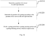
- the step of forming grating periods corresponding to the viewing distance may further comprise: determining a position of the viewer in a left-right direction, and determining a position of the grating according to the position of the viewer in the left-right direction.
- the step of forming grating periods corresponding to the viewing distance may further comprise: dividing the grating period into a grating opening portion and a grating blocking portion, which are equal in size.
- the grating driving method may further comprise determining the level of each grating driving signal in the set of grating driving signals before driving the plurality of grating control electrodes in each grating period by the plurality of grating driving signals.
- the naked-eye 3D display may comprise a 2D display screen and any grating driving circuit as stated above.
- the inventor realizes that the current naked-eye 3D display technology may achieve a good 3D effect at an optimal viewing distance, but when a viewer deviates from the optimal viewing distance, that is, when human eyes move in the front-rear direction relative to a screen, the left eye and the right eye may not obtain a corresponding view independently at a place deviating from the optimal viewing distance, crosstalk significantly increases and the 3D effect gets worse because it is impossible to adjust the grating period in a current grating driving mode.
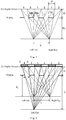
- Fig. 1 schematically shows the 3D display principle of the naked-eye 3D display.
- the naked-eye 3D display comprises a 2D display screen and a grating.
- the grating herein may be a liquid crystal grating or a grating made of an electrochromic material.
- the 2D display screen can show Views 1 and Views 2 which are spaced alternately, and there are subtle nuances between adjacent View 1 and View 2.
- the grating comprises a grating opening portion W w and a grating blocking portion W b . Through the grating opening portion W w , the left eye can see View 1, but not View 2, whereas the right eye can see View 2, but not View 1.
- the view seen by the left eye and the view seen by the right eye are blended in brain so as to form a stereoscopic image therein.
- the sum of the grating opening portion W w and the grating blocking portion W b constitutes a grating period C 0 .
- H is the grating placement height, i.e., the distance between the grating and the 2D display screen. In comparison with the 2D display screen, the grating is placed closer to human eyes.
- S 0 is the optimal viewing distance
- L is an interpupillary distance of human eyes
- P is a pixel or sub-pixel width of the 2D display screen.
- the left eye and right eye can see View 1 and View 2 respectively, but one eye cannot see the view seen by the other eye.
- a best 3D display effect can be achieved.
- Fig. 2 schematically shows an optical path map formed when a viewing distance deviates from an optimal viewing distance S 0 according to an embodiment of the present disclosure.
- a viewer moves away from a screen at the optimal viewing distance S 0 .
- the left eye can see an area CD of the 2D display screen through the grating opening portion AB, and the area CD is the left-eye View 1.
- the left eye can see an area EF of the 2D display screen through the grating opening portion AB. It may be found that the area ED belongs to View 1, and the area DF belongs to View 2.
- the front-rear movement range is labelled as ⁇ S, and human eyes can still see a 3D image within the range from S 0 - ⁇ S to S 0 + ⁇ S.
- ⁇ S Theoretically speaking, crosstalk will occur when eyes deviate from the optimal viewing distance S 0 , but human eyes may not observe the crosstalk within that range and the 3D effect can still be deemed as satisfactory. Therefore, the range from S 0 - ⁇ S to S 0 + ⁇ S may be regarded as the optimal viewing distance.
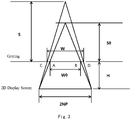
- Fig. 3 shows a schematic view of a naked-eye 3D grating with an adjustable viewing distance according to an embodiment of the present disclosure.
- the horizontal resolution of the 2D display screen is 2N
- the 3D display uses two views, namely View 1 and View 2 as stated above, then it may be known that the total number of grating periods is N.
- the total grating width is W 0 .
- the total grating width is W.
- the grating placement height H may be set according to the optimal viewing distance S 0 .
- a target viewing distance may be predetermined when designing and manufacturing displays.
- a target viewing distance of a desktop display can range from 65cm to 90cm, and a target viewing distance of a TV may be determined according to the size of the TV and the size of the room where the TV is going to be placed.
- the optimal viewing distance S 0 may be set according to the target viewing distance, and then the grating placement height H may be set according to the optimal viewing distance S 0 .
- each grating period is formed by a plurality of grating driving electrodes
- each grating period calculated according to each viewing distance may comprise an integral number of electrodes, so as to ensure an optimal 3D effect in the grating period.
- the grating period C 0 corresponding to the optimal viewing distance S 0 is determined in advance according to actual technical conditions and technical requirements, and may realize an optimal 3D effect, the grating period C 0 will comprise an integral number of electrodes.
- ⁇ C is a width of an integral number of electrodes, namely a width of at least one electrode.
- ⁇ C is a width of one electrode so as to guarantee the uniformity of grating driving electrodes.
- the above is related to the calculation of the grating period based on the viewing distance.
- grating driving electrode and “electrode” may be used interchangeably.
- the present disclosure provides a grating driving circuit and method, which allow that the viewing distance of the naked-eye 3D grating is adjustable. That is to say, even though human eyes move in the front-rear direction relative to a screen, they may still see a corresponding left-eye view and a corresponding right-eye view respectively with less crosstalk and an optimal 3D effect.
- the grating driving circuit and method as described above may determine, according to the distance between the viewer and the grating, a set of driving signals corresponding to the distance and form a grating period corresponding to the distance. In this way, naked-eye 3D display with adjustable viewing distances may be realized.
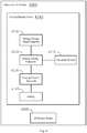
- Fig. 4 schematically shows a structural block diagram of a naked-eye 3D display 4000 according to an embodiment of the present disclosure.
- the naked-eye 3D display 4000 may comprise a grating driving circuit 4100 and a 2D display screen 4200.
- the grating driving circuit 4100 may comprise a grating driving signal generator 4110, a grating driving controller 4120, a plurality of grating control electrodes 4130, a grating 4140 and a viewpoint tracker 4150.
- the grating 4140 may comprise a plurality of grating elements, each having an on/off state controlled by a grating driving signal.
- the viewpoint tracker 4150 may be configured to determine a viewing distance S of a viewer.
- Each of the plurality of grating control electrodes 4130 may be configured to control the on/off state of a grating element in the grating 4140 that corresponds to the grating control electrode 4130 according to a grating driving signal, so as to decide whether the grating element transmits light or blocks light, that is, whether the grating element belongs to a grating opening portion or a grating blocking portion.
- the grating driving signal generator 4110 may be configured to generate a plurality of sets of grating driving signals with each set corresponding to a viewing distance and including a plurality of grating driving signals.
- the grating driving controller 4120 may be configured to determine a set of grating driving signals that corresponds to the viewing distance, and configured to form a grating period corresponding to the viewing distance, each grating period including a plurality of grating control electrodes that correspond to the plurality of grating driving signals in a one-to-one relationship.
- the grating driving controller 4120 may also comprise a plurality of switch units configured to connect the set of grating driving signals that corresponds to the viewing distance and disconnect other sets of grating driving signals.
- the grating 4140 may comprise two substrates that are oppositely disposed and an liquid crystal layer or electrochromic material layer located between the two substrates.
- the grating 4140 may comprise a liquid crystal grating or an electrochromic material grating.
- the present disclosure is not limited to a liquid crystal grating or an electrochromic material grating, but may be applied to any grating capable of controlling the on/off states of its grating elements via grating driving signals.
- the viewpoint tracker 4150 may also be configured to determine a position of the viewer in a left-right direction, and the grating driving controller 4120 may also be configured to determine a position of the grating according to the position of the viewer in the left-right direction.
- the viewpoint tracker 4150 may comprise a camera, an eye tracker or an infrared rangefinder, and any other device capable of determining the distance or position of the viewer.
- each grating period comprises a grating opening portion and a grating blocking portion, which may be equal in size.
- the grating driving controller 4120 may also be configured to determine levels of grating driving signals in the set of grating driving signals. Thus, there may be formed the grating opening portion and the grating blocking portion for each grating period.
- the grating driving circuit is provided with a series of grating driving signals that are divided into a plurality of sets with each set corresponding to a specific viewing distance.
- the viewpoint tracker records the viewing distance and activates a certain set of grating driving signals corresponding to the viewing distance so as to generate the grating period corresponding to the viewing distance.
- the grating period corresponds to the viewing distance in a one-to-one relationship. In doing so, it is possible to track human eyes moving in a front-rear direction, such that the viewing distance is adjustable, 3D crosstalk may be significantly reduced and a 3D effect may be greatly improved.
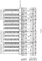
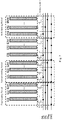
- Figs. 5 to 8 respectively show a structural schematic view of a naked-eye 3D grating driving circuit with an adjustable viewing distance according to some embodiments of the present disclosure.
- the grating driving circuit is designed to comprise a number A of adjusting distances, wherein A is an integer and greater than or equal to 2.
- A is an integer and greater than or equal to 2.
- these adjustable distances are viewing distances under an ideal condition with no crosstalk at all.
- a 3D effect may also be achieved within a front-rear movement range ⁇ S around individual adjustable distances. However, it could be seen from the optical path map that there may be very small crosstalk in that range.
- the grating driving signals may be divided into A sets with each set of grating driving signals corresponding to a specific viewing distance.
- a first set of grating driving signals comprises M grating driving signals
- a second set of grating driving signals comprises M+1 grating driving signals
- a third set of grating driving signals comprises M+2 grating driving signals
- the last set of grating driving signals comprises M+A-1 grating driving signals
- the middle set of grating driving signals comprises M grating driving signals and the difference between two adjacent sets of grating driving signals is one grating driving signal, there will be required to provide AM grating driving signals in total.
- the first set of grating driving signals comprises M ⁇ A ⁇ 1 2 grating driving signals
- the last set of grating driving signals comprises M + A ⁇ 1 2 grating driving signals.
- the viewpoint tracker determines and records the viewing distance. Then the number M of grating control electrodes in a grating period corresponding to the viewing distance and the number M of grating driving signals corresponding to the viewing distance may be determined according to the viewing distance, and in turn the sets of grating driving signals corresponding to the viewing distance may be determined. In doing so, the grating driving circuit may activate the set of grating driving signals that corresponds to the viewing distance, so as to generate and form a grating period corresponding to the viewing distance. In some embodiments, the set of grating driving signals that corresponds to the viewing distance may be retrieved from a pre-stored lookup table according to the viewing distance.
- each grating period comprises M electrodes, each electrode has a width of W e , and the total number of grating periods is N.
- the electrodes in the first grating period are numbered as E 11 , E 12 ,..., E 1M ; the electrodes in the second grating period are numbered as E 21 , E 22 ,..., E 2M ; and by analogy, the electrodes in the N-th grating period are numbered as E N1 , E N2 ,..., E NM .
- the grating driving circuit is also provided with 2M+1 grating driving signals that are divided into two sets, wherein the first set comprises the grating driving signals DS 1 to DS M , and the second set comprises the grating driving signals DS M+1 and DS 2M+1 .
- the electrodes in the grating are connected with the grating driving signals DS 1 to DS M by a switch unit 1.
- the first electrode in each grating period namely electrodes E 11 , E 21 , E 31 ,..., E N1
- the second electrode in each grating period namely electrodes E 12 , E 22 , E 32 ,..., E N2
- the last electrode in each grating period namely electrodes, E 1M , E 2M , E 3M ,..., E NM , is connected with the driving signal DS M by the switch unit 1.
- the grating period changes, assuming that a grating period is enlarged by adding one electrode to each grating period. At this point, the number of electrodes in each grating period is changed to M+1, each electrode still has a width of W e , and the total number of grating periods is still N.
- the electrodes in the first grating period are numbered as E 11 , E 12 ,..., E 1M , E 1(M+1) ; the electrodes in the second grating period are numbered as E 21 , E 22 ,..., E 2M , E 2(M+1) ; and by analogy, the electrodes in the N-th grating period are numbered as E N1 , E N2 ,..., E NM , E N(M+1) .
- the electrodes within the grating are connected with grating driving signals by the switch unit, such as the switch transistor. As shown in Fig.
- the first electrode in each grating period namely electrodes E 11 , E 21 , E 31 ,..., E N1
- the second electrode in each grating period namely electrodes E 12 , E 22 , E 32 ,..., E N2
- the last electrode in each grating period namely electrodes, E 1(M+1) , E 2(M+1) , E 3(M+1) ,..., E N(M+1)
- the switch unit 2 is connected with the driving signal DS 2M+1 by the switch unit 2.
- the grating driving circuit may be simplified as shown in Fig. 7 , and the grating period comprises M electrodes and corresponds to the grating driving signals DS 1 to DS M .
- the grating driving circuit may be simplified as shown in Fig. 8 , and the grating period comprises M+1 electrodes and corresponds to the grating driving signals DS M+1 to DS 2M+1 .
- circuit structures shown in Figs. 5 to 8 utilizes two sets of grating driving signals, it is also possible, in other embodiments, to use more than two sets of grating driving signals, each set of grating driving signals corresponds to a viewing distance, and decision on which set of grating driving signals is transmitted to the electrodes in the grating is made through switch units.
- human eyes can still move in a front-rear direction within a range ⁇ S around the optimal viewing distance S 0 .
- human eyes can still see a 3D image, and a 3D effect may still meet the requirement to some extent.
- the difference between the two distances S 1 and S 2 is less than ⁇ S, it is possible to realize the naked-eye 3D display with continuously adjustable distances.
- a certain actual distance is between the distances S 1 and S 2 , one can decide which grating period and which set of grating driving signals are to be used according to which one of the distances S 1 and S 2 is closer to the actual distance.
- Fig. 9 shows an optical path map formed when eyes move in a left-right direction at an optimal viewing distance S 0 according to an embodiment of the present disclosure.
- the left eye when the left eye is at the left-eye position 1, the left eye can see P1, P3, namely the left-eye View 1, rather than the right-eye View 2, through the grating opening F 0 G 0 .
- the right eye can see P2, P4, namely the right-eye View 2, rather than the left-eye View 1, through the grating opening.
- the view seen by the left eye and the view seen by the right eye may be blended by a brain, thereby forming a stereoscopic image in the brain.
- the grating opening may be adjusted to F 1 G 1 , and the left eye can see P1, namely the left-eye View 1. It may be seen that when human eyes move, the position of the grating opening may be adjusted in real time to ensure that position on the 2D display screen seen by human eyes remains unchanged, thereby guaranteeing the 3D effect. It may be understood that, as shown in Fig.
- the adjustment amount L2 of the position of the grating opening may be determined according to the left-right human eye movement distance L1, the viewing distance S and the grating placement height H.
- the adjustment amount is a width of an integral number of grating control electrodes.
- the electrodes in the first grating period would be E 12 , E 13 ,..., B 1M , E 21 ; the electrodes in the second grating period would be E 22 ,..., E 2M , E 31 ; and by analogy, the electrodes in the N-th grating period would be E N2 ,..., E NM , E N(M+1) .
- Fig. 10 illustrates a schematic flow chart showing a grating driving method according to an embodiment of the present disclosure.
- the grating driving method may comprise the steps of:
- the grating driving method may also comprise the step of S1040, in which levels of the plurality of grating driving signals in the set of grating driving signals are determined before driving the plurality of grating control electrodes in each grating period by these grating driving signals.
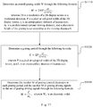
- Fig.11 illustrates a schematic flow chart showing a method for determining a set of grating driving signals corresponding to a viewing distance S according to an embodiment of the present disclosure.
- the method for determining a set of grating driving signals corresponding to a viewing distance comprises the steps of:
- Fig. 12 illustrates a schematic flow chart showing a method for forming grating periods corresponding to a viewing distance according to an embodiment of the present disclosure. As shown in Fig. 12 , the method for forming grating periods corresponding to a viewing distance may further comprise the steps of:
- one or more devices may be embodied in the same hardware project.
Landscapes
- Physics & Mathematics (AREA)
- Engineering & Computer Science (AREA)
- General Physics & Mathematics (AREA)
- Optics & Photonics (AREA)
- Nonlinear Science (AREA)
- General Engineering & Computer Science (AREA)
- Theoretical Computer Science (AREA)
- Multimedia (AREA)
- Signal Processing (AREA)
- Human Computer Interaction (AREA)
- Testing, Inspecting, Measuring Of Stereoscopic Televisions And Televisions (AREA)
- Liquid Crystal (AREA)
Applications Claiming Priority (2)
| Application Number | Priority Date | Filing Date | Title |
|---|---|---|---|
| CN201810089682.6A CN110095871B (zh) | 2018-01-30 | 2018-01-30 | 光栅驱动电路、驱动方法以及裸眼3d显示器 |
| PCT/CN2018/104548 WO2019148842A1 (zh) | 2018-01-30 | 2018-09-07 | 光栅驱动电路、驱动方法以及裸眼3d显示器 |
Publications (3)
| Publication Number | Publication Date |
|---|---|
| EP3748418A1 true EP3748418A1 (de) | 2020-12-09 |
| EP3748418A4 EP3748418A4 (de) | 2021-09-01 |
| EP3748418B1 EP3748418B1 (de) | 2024-11-20 |
Family
ID=67442295
Family Applications (1)
| Application Number | Title | Priority Date | Filing Date |
|---|---|---|---|
| EP18863814.2A Active EP3748418B1 (de) | 2018-01-30 | 2018-09-07 | Gittertreiberschaltung, ansteuerungsverfahren und autostereoskopische 3d-anzeige |
Country Status (4)
| Country | Link |
|---|---|
| US (1) | US10955684B2 (de) |
| EP (1) | EP3748418B1 (de) |
| CN (1) | CN110095871B (de) |
| WO (1) | WO2019148842A1 (de) |
Families Citing this family (12)
| Publication number | Priority date | Publication date | Assignee | Title |
|---|---|---|---|---|
| CN110703443A (zh) * | 2019-10-22 | 2020-01-17 | 华北科技学院 | 一种vr显示方法及vr观看装置 |
| CN112748585B (zh) * | 2019-10-30 | 2022-07-19 | 驻景(广州)科技有限公司 | 一种小间距视区导引式三维显示系统和方法 |
| CN112929635A (zh) * | 2019-12-05 | 2021-06-08 | 北京芯海视界三维科技有限公司 | 裸眼3d显示屏的显示控制方法、多视点裸眼3d显示器 |
| US12007587B2 (en) | 2020-11-18 | 2024-06-11 | Boe Technology Group Co., Ltd. | Grating, grating driving method and 3D display device |
| JP2022106593A (ja) * | 2021-01-07 | 2022-07-20 | 公立大学法人大阪 | 3次元表示装置 |
| TWI800959B (zh) * | 2021-10-22 | 2023-05-01 | 宏碁股份有限公司 | 眼球追蹤方法及眼球追蹤裝置 |
| US12313860B2 (en) * | 2021-11-23 | 2025-05-27 | Boe Technology Group Co., Ltd. | Device and method for eliminating stray light of Fresnel lens, and optical apparatus |
| AU2022202221B1 (en) * | 2022-01-21 | 2022-08-04 | Metrix Group Pty Ltd | Animated Perforated Images |
| CN116540455B (zh) | 2022-01-26 | 2026-04-17 | 合肥京东方光电科技有限公司 | 一种光栅调节装置、3d显示装置 |
| CN114584754B (zh) * | 2022-02-28 | 2023-12-26 | 广东未来科技有限公司 | 3d显示方法及相关装置 |
| CN114488373B (zh) * | 2022-02-28 | 2024-01-12 | 合肥京东方光电科技有限公司 | 一种光栅调节装置、3d显示装置及其控制方法 |
| CN119916605A (zh) * | 2023-10-31 | 2025-05-02 | 京东方科技集团股份有限公司 | 光栅驱动模块及相关设备、光栅调节方法及光栅测试方法 |
Family Cites Families (14)
| Publication number | Priority date | Publication date | Assignee | Title |
|---|---|---|---|---|
| CN102096228B (zh) * | 2010-12-17 | 2012-07-04 | 湖南创图视维科技有限公司 | 一种显示系统和显示方法 |
| KR20120134023A (ko) * | 2011-05-31 | 2012-12-11 | 소니 주식회사 | 표시 장치, 배리어 장치, 배리어 구동 회로 및 배리어 장치 구동 방법 |
| CN102629009B (zh) * | 2011-10-25 | 2016-02-03 | 京东方科技集团股份有限公司 | 裸眼三维图像显示方法及装置 |
| CN102572483B (zh) * | 2011-12-02 | 2014-08-13 | 深圳超多维光电子有限公司 | 跟踪式裸眼立体显示控制方法、装置及显示设备、系统 |
| CN102650742A (zh) * | 2012-05-16 | 2012-08-29 | 天马微电子股份有限公司 | 自由立体显示装置及方法 |
| CN102710956B (zh) * | 2012-06-04 | 2014-12-31 | 天马微电子股份有限公司 | 一种裸眼立体追踪显示方法及装置 |
| US9563096B2 (en) * | 2014-12-17 | 2017-02-07 | Shenzhen Magic Eye Technology Co., Ltd. | 3D display apparatus and dynamic grating |
| CN104597681B (zh) * | 2014-12-30 | 2017-12-01 | 深圳市魔眼科技有限公司 | 一种电子光栅及全息显示装置 |
| CN105100783B (zh) * | 2015-08-19 | 2018-03-23 | 京东方科技集团股份有限公司 | 3d显示装置及3d显示方法 |
| CN105445948B (zh) * | 2016-01-04 | 2018-02-16 | 京东方科技集团股份有限公司 | 一种裸眼3d显示装置及显示方法 |
| CN105954956B (zh) * | 2016-05-26 | 2019-02-15 | 京东方科技集团股份有限公司 | 3d显示面板及其控制方法 |
| CN106526878B (zh) * | 2016-12-08 | 2019-04-05 | 南京大学 | 多维度自由立体显示装置 |
| CN106918956B (zh) * | 2017-05-12 | 2019-01-22 | 京东方科技集团股份有限公司 | 一种液晶光栅、3d显示装置及其驱动方法 |
| CN107229131A (zh) * | 2017-06-12 | 2017-10-03 | 深圳市华星光电技术有限公司 | 用于驱动裸眼3d液晶棱镜的系统和方法 |
-
2018
- 2018-01-30 CN CN201810089682.6A patent/CN110095871B/zh active Active
- 2018-09-07 EP EP18863814.2A patent/EP3748418B1/de active Active
- 2018-09-07 WO PCT/CN2018/104548 patent/WO2019148842A1/zh not_active Ceased
- 2018-09-07 US US16/339,063 patent/US10955684B2/en active Active
Also Published As
| Publication number | Publication date |
|---|---|
| CN110095871A (zh) | 2019-08-06 |
| CN110095871B (zh) | 2020-12-08 |
| EP3748418B1 (de) | 2024-11-20 |
| US20200183182A1 (en) | 2020-06-11 |
| US10955684B2 (en) | 2021-03-23 |
| EP3748418A4 (de) | 2021-09-01 |
| WO2019148842A1 (zh) | 2019-08-08 |
Similar Documents
| Publication | Publication Date | Title |
|---|---|---|
| EP3748418B1 (de) | Gittertreiberschaltung, ansteuerungsverfahren und autostereoskopische 3d-anzeige | |
| DE102011057187B4 (de) | Stereoskopische Bildanzeigevorrichtung und Verfahren zum Einstellen eines stereoskopischen Bildes derselben | |
| US7825999B2 (en) | Autostereoscopic display | |
| EP2815577B1 (de) | Autostereoskopische anzeigevorrichtung und ansteuerverfahren | |
| EP1750459B1 (de) | Hochauflösende autostereoskopische Anzeigevorrichtung | |
| US7092003B1 (en) | 3-D imaging arrangements | |
| KR100728204B1 (ko) | 2차원 영상과 3차원 영상 겸용 디스플레이 장치 | |
| CN103873844B (zh) | 多视点自动立体显示器及控制其最佳观看距离的方法 | |
| US11483546B2 (en) | Auto-stereoscopic display device with a striped backlight and two lenticular lens arrays | |
| KR101380517B1 (ko) | 멀티 뷰 무안경 입체 영상 표시장치와 그 최적 시청 거리 제어 방법 | |
| US20130076724A1 (en) | Stereoscopic Image Display Device and Driving Method for the Same | |
| EP2811746A1 (de) | Glasfreie 3d-bildanzeigevorrichtung zur glättung des sichtfeldes und minimierung von dynamischem übersprechen | |
| TWI482999B (zh) | 立體顯示裝置 | |
| US10200682B2 (en) | Active grating, three-dimensional display device and three-dimensional display method | |
| US20130057575A1 (en) | Stereoscopic Image Display Device And Method For Driving The Same | |
| KR100878130B1 (ko) | 이용자 제어를 가진 자동입체 이미지 디스플레이 장치 및 방법 | |
| KR102197536B1 (ko) | 이동 플리커가 감소된 입체영상 표시장치 | |
| KR102420041B1 (ko) | 디스플레이 장치 및 그 제어방법 | |
| Kakeya et al. | Time-division quadruplexing parallax barrier with subpixel-based slit control | |
| CN102917231A (zh) | 立体显示设备及驱动方法 | |
| US20130293446A1 (en) | Method and apparatus for stereoscopic image display | |
| US20080169997A1 (en) | Multi-dimensional image selectable display device | |
| Watanabe et al. | A full-HD super-multiview display based on adaptive time-division multiplexing parallax barrier | |
| KR101908511B1 (ko) | 입체 영상 표시 장치 및 이의 구동 방법 | |
| KR101951297B1 (ko) | 영상표시장치 |
Legal Events
| Date | Code | Title | Description |
|---|---|---|---|
| STAA | Information on the status of an ep patent application or granted ep patent |
Free format text: STATUS: UNKNOWN |
|
| STAA | Information on the status of an ep patent application or granted ep patent |
Free format text: STATUS: THE INTERNATIONAL PUBLICATION HAS BEEN MADE |
|
| PUAI | Public reference made under article 153(3) epc to a published international application that has entered the european phase |
Free format text: ORIGINAL CODE: 0009012 |
|
| STAA | Information on the status of an ep patent application or granted ep patent |
Free format text: STATUS: REQUEST FOR EXAMINATION WAS MADE |
|
| 17P | Request for examination filed |
Effective date: 20190412 |
|
| AK | Designated contracting states |
Kind code of ref document: A1 Designated state(s): AL AT BE BG CH CY CZ DE DK EE ES FI FR GB GR HR HU IE IS IT LI LT LU LV MC MK MT NL NO PL PT RO RS SE SI SK SM TR |
|
| AX | Request for extension of the european patent |
Extension state: BA ME |
|
| DAV | Request for validation of the european patent (deleted) | ||
| DAX | Request for extension of the european patent (deleted) | ||
| RIN1 | Information on inventor provided before grant (corrected) |
Inventor name: YANG, MING Inventor name: CHEN, XIAOCHUAN Inventor name: ZHAO, WENQING Inventor name: CHEN, CHEN-YU Inventor name: ZHU, JINYE |
|
| REG | Reference to a national code |
Ref country code: DE Ref legal event code: R079 Free format text: PREVIOUS MAIN CLASS: G02B0027220000 Ipc: G02B0030310000 Ref document number: 602018076826 Country of ref document: DE |
|
| A4 | Supplementary search report drawn up and despatched |
Effective date: 20210804 |
|
| RIC1 | Information provided on ipc code assigned before grant |
Ipc: G02B 30/31 20200101AFI20210729BHEP Ipc: G02B 27/00 20060101ALI20210729BHEP Ipc: G02F 1/29 20060101ALI20210729BHEP Ipc: G02B 27/01 20060101ALI20210729BHEP Ipc: G06F 3/01 20060101ALI20210729BHEP Ipc: G02B 30/27 20200101ALI20210729BHEP |
|
| STAA | Information on the status of an ep patent application or granted ep patent |
Free format text: STATUS: EXAMINATION IS IN PROGRESS |
|
| 17Q | First examination report despatched |
Effective date: 20230227 |
|
| REG | Reference to a national code |
Ref country code: DE Ref legal event code: R079 Free format text: PREVIOUS MAIN CLASS: G02B0030310000 Ipc: H04N0013310000 Ref document number: 602018076826 Country of ref document: DE |
|
| GRAP | Despatch of communication of intention to grant a patent |
Free format text: ORIGINAL CODE: EPIDOSNIGR1 |
|
| STAA | Information on the status of an ep patent application or granted ep patent |
Free format text: STATUS: GRANT OF PATENT IS INTENDED |
|
| RIC1 | Information provided on ipc code assigned before grant |
Ipc: G02F 1/29 20060101ALI20240601BHEP Ipc: G02B 27/00 20060101ALI20240601BHEP Ipc: G02B 30/31 20200101ALI20240601BHEP Ipc: H04N 13/376 20180101ALI20240601BHEP Ipc: H04N 13/31 20180101AFI20240601BHEP |
|
| INTG | Intention to grant announced |
Effective date: 20240625 |
|
| GRAS | Grant fee paid |
Free format text: ORIGINAL CODE: EPIDOSNIGR3 |
|
| GRAA | (expected) grant |
Free format text: ORIGINAL CODE: 0009210 |
|
| STAA | Information on the status of an ep patent application or granted ep patent |
Free format text: STATUS: THE PATENT HAS BEEN GRANTED |
|
| AK | Designated contracting states |
Kind code of ref document: B1 Designated state(s): AL AT BE BG CH CY CZ DE DK EE ES FI FR GB GR HR HU IE IS IT LI LT LU LV MC MK MT NL NO PL PT RO RS SE SI SK SM TR |
|
| REG | Reference to a national code |
Ref country code: GB Ref legal event code: FG4D |
|
| REG | Reference to a national code |
Ref country code: CH Ref legal event code: EP |
|
| REG | Reference to a national code |
Ref country code: DE Ref legal event code: R096 Ref document number: 602018076826 Country of ref document: DE |
|
| REG | Reference to a national code |
Ref country code: IE Ref legal event code: FG4D |
|
| REG | Reference to a national code |
Ref country code: LT Ref legal event code: MG9D |
|
| REG | Reference to a national code |
Ref country code: NL Ref legal event code: MP Effective date: 20241120 |
|
| PG25 | Lapsed in a contracting state [announced via postgrant information from national office to epo] |
Ref country code: HR Free format text: LAPSE BECAUSE OF FAILURE TO SUBMIT A TRANSLATION OF THE DESCRIPTION OR TO PAY THE FEE WITHIN THE PRESCRIBED TIME-LIMIT Effective date: 20241120 Ref country code: PT Free format text: LAPSE BECAUSE OF FAILURE TO SUBMIT A TRANSLATION OF THE DESCRIPTION OR TO PAY THE FEE WITHIN THE PRESCRIBED TIME-LIMIT Effective date: 20250320 Ref country code: IS Free format text: LAPSE BECAUSE OF FAILURE TO SUBMIT A TRANSLATION OF THE DESCRIPTION OR TO PAY THE FEE WITHIN THE PRESCRIBED TIME-LIMIT Effective date: 20250320 |
|
| PG25 | Lapsed in a contracting state [announced via postgrant information from national office to epo] |
Ref country code: NL Free format text: LAPSE BECAUSE OF FAILURE TO SUBMIT A TRANSLATION OF THE DESCRIPTION OR TO PAY THE FEE WITHIN THE PRESCRIBED TIME-LIMIT Effective date: 20241120 Ref country code: FI Free format text: LAPSE BECAUSE OF FAILURE TO SUBMIT A TRANSLATION OF THE DESCRIPTION OR TO PAY THE FEE WITHIN THE PRESCRIBED TIME-LIMIT Effective date: 20241120 |
|
| REG | Reference to a national code |
Ref country code: AT Ref legal event code: MK05 Ref document number: 1744609 Country of ref document: AT Kind code of ref document: T Effective date: 20241120 |
|
| PG25 | Lapsed in a contracting state [announced via postgrant information from national office to epo] |
Ref country code: BG Free format text: LAPSE BECAUSE OF FAILURE TO SUBMIT A TRANSLATION OF THE DESCRIPTION OR TO PAY THE FEE WITHIN THE PRESCRIBED TIME-LIMIT Effective date: 20241120 |
|
| PG25 | Lapsed in a contracting state [announced via postgrant information from national office to epo] |
Ref country code: ES Free format text: LAPSE BECAUSE OF FAILURE TO SUBMIT A TRANSLATION OF THE DESCRIPTION OR TO PAY THE FEE WITHIN THE PRESCRIBED TIME-LIMIT Effective date: 20241120 |
|
| PG25 | Lapsed in a contracting state [announced via postgrant information from national office to epo] |
Ref country code: NO Free format text: LAPSE BECAUSE OF FAILURE TO SUBMIT A TRANSLATION OF THE DESCRIPTION OR TO PAY THE FEE WITHIN THE PRESCRIBED TIME-LIMIT Effective date: 20250220 |
|
| PG25 | Lapsed in a contracting state [announced via postgrant information from national office to epo] |
Ref country code: LV Free format text: LAPSE BECAUSE OF FAILURE TO SUBMIT A TRANSLATION OF THE DESCRIPTION OR TO PAY THE FEE WITHIN THE PRESCRIBED TIME-LIMIT Effective date: 20241120 Ref country code: GR Free format text: LAPSE BECAUSE OF FAILURE TO SUBMIT A TRANSLATION OF THE DESCRIPTION OR TO PAY THE FEE WITHIN THE PRESCRIBED TIME-LIMIT Effective date: 20250221 Ref country code: AT Free format text: LAPSE BECAUSE OF FAILURE TO SUBMIT A TRANSLATION OF THE DESCRIPTION OR TO PAY THE FEE WITHIN THE PRESCRIBED TIME-LIMIT Effective date: 20241120 |
|
| PG25 | Lapsed in a contracting state [announced via postgrant information from national office to epo] |
Ref country code: PL Free format text: LAPSE BECAUSE OF FAILURE TO SUBMIT A TRANSLATION OF THE DESCRIPTION OR TO PAY THE FEE WITHIN THE PRESCRIBED TIME-LIMIT Effective date: 20241120 |
|
| PG25 | Lapsed in a contracting state [announced via postgrant information from national office to epo] |
Ref country code: RS Free format text: LAPSE BECAUSE OF FAILURE TO SUBMIT A TRANSLATION OF THE DESCRIPTION OR TO PAY THE FEE WITHIN THE PRESCRIBED TIME-LIMIT Effective date: 20250220 |
|
| PG25 | Lapsed in a contracting state [announced via postgrant information from national office to epo] |
Ref country code: SM Free format text: LAPSE BECAUSE OF FAILURE TO SUBMIT A TRANSLATION OF THE DESCRIPTION OR TO PAY THE FEE WITHIN THE PRESCRIBED TIME-LIMIT Effective date: 20241120 |
|
| PG25 | Lapsed in a contracting state [announced via postgrant information from national office to epo] |
Ref country code: DK Free format text: LAPSE BECAUSE OF FAILURE TO SUBMIT A TRANSLATION OF THE DESCRIPTION OR TO PAY THE FEE WITHIN THE PRESCRIBED TIME-LIMIT Effective date: 20241120 |
|
| PG25 | Lapsed in a contracting state [announced via postgrant information from national office to epo] |
Ref country code: EE Free format text: LAPSE BECAUSE OF FAILURE TO SUBMIT A TRANSLATION OF THE DESCRIPTION OR TO PAY THE FEE WITHIN THE PRESCRIBED TIME-LIMIT Effective date: 20241120 |
|
| PG25 | Lapsed in a contracting state [announced via postgrant information from national office to epo] |
Ref country code: RO Free format text: LAPSE BECAUSE OF FAILURE TO SUBMIT A TRANSLATION OF THE DESCRIPTION OR TO PAY THE FEE WITHIN THE PRESCRIBED TIME-LIMIT Effective date: 20241120 |
|
| PG25 | Lapsed in a contracting state [announced via postgrant information from national office to epo] |
Ref country code: SK Free format text: LAPSE BECAUSE OF FAILURE TO SUBMIT A TRANSLATION OF THE DESCRIPTION OR TO PAY THE FEE WITHIN THE PRESCRIBED TIME-LIMIT Effective date: 20241120 |
|
| PG25 | Lapsed in a contracting state [announced via postgrant information from national office to epo] |
Ref country code: CZ Free format text: LAPSE BECAUSE OF FAILURE TO SUBMIT A TRANSLATION OF THE DESCRIPTION OR TO PAY THE FEE WITHIN THE PRESCRIBED TIME-LIMIT Effective date: 20241120 |
|
| PG25 | Lapsed in a contracting state [announced via postgrant information from national office to epo] |
Ref country code: IT Free format text: LAPSE BECAUSE OF FAILURE TO SUBMIT A TRANSLATION OF THE DESCRIPTION OR TO PAY THE FEE WITHIN THE PRESCRIBED TIME-LIMIT Effective date: 20241120 |
|
| REG | Reference to a national code |
Ref country code: DE Ref legal event code: R097 Ref document number: 602018076826 Country of ref document: DE |
|
| PG25 | Lapsed in a contracting state [announced via postgrant information from national office to epo] |
Ref country code: SE Free format text: LAPSE BECAUSE OF FAILURE TO SUBMIT A TRANSLATION OF THE DESCRIPTION OR TO PAY THE FEE WITHIN THE PRESCRIBED TIME-LIMIT Effective date: 20241120 |
|
| PLBE | No opposition filed within time limit |
Free format text: ORIGINAL CODE: 0009261 |
|
| STAA | Information on the status of an ep patent application or granted ep patent |
Free format text: STATUS: NO OPPOSITION FILED WITHIN TIME LIMIT |
|
| PGFP | Annual fee paid to national office [announced via postgrant information from national office to epo] |
Ref country code: DE Payment date: 20250919 Year of fee payment: 8 |
|
| 26N | No opposition filed |
Effective date: 20250821 |
|
| REG | Reference to a national code |
Ref country code: CH Ref legal event code: H13 Free format text: ST27 STATUS EVENT CODE: U-0-0-H10-H13 (AS PROVIDED BY THE NATIONAL OFFICE) Effective date: 20260425 |