EP3748397B1 - Procédé et dispositif de détection résolue localement des émissions sonores, en particulier des émissions ultrasonores - Google Patents
Procédé et dispositif de détection résolue localement des émissions sonores, en particulier des émissions ultrasonores Download PDFInfo
- Publication number
- EP3748397B1 EP3748397B1 EP19215886.3A EP19215886A EP3748397B1 EP 3748397 B1 EP3748397 B1 EP 3748397B1 EP 19215886 A EP19215886 A EP 19215886A EP 3748397 B1 EP3748397 B1 EP 3748397B1
- Authority
- EP
- European Patent Office
- Prior art keywords
- sound
- array
- intensity map
- spatial area
- measurements
- Prior art date
- Legal status (The legal status is an assumption and is not a legal conclusion. Google has not performed a legal analysis and makes no representation as to the accuracy of the status listed.)
- Active
Links
Images

Classifications
-
- G—PHYSICS
- G01—MEASURING; TESTING
- G01S—RADIO DIRECTION-FINDING; RADIO NAVIGATION; DETERMINING DISTANCE OR VELOCITY BY USE OF RADIO WAVES; LOCATING OR PRESENCE-DETECTING BY USE OF THE REFLECTION OR RERADIATION OF RADIO WAVES; ANALOGOUS ARRANGEMENTS USING OTHER WAVES
- G01S15/00—Systems using the reflection or reradiation of acoustic waves, e.g. sonar systems
- G01S15/88—Sonar systems specially adapted for specific applications
- G01S15/89—Sonar systems specially adapted for specific applications for mapping or imaging
-
- G—PHYSICS
- G01—MEASURING; TESTING
- G01N—INVESTIGATING OR ANALYSING MATERIALS BY DETERMINING THEIR CHEMICAL OR PHYSICAL PROPERTIES
- G01N29/00—Investigating or analysing materials by the use of ultrasonic, sonic or infrasonic waves; Visualisation of the interior of objects by transmitting ultrasonic or sonic waves through the object
- G01N29/04—Analysing solids
- G01N29/043—Analysing solids in the interior, e.g. by shear waves
-
- G—PHYSICS
- G01—MEASURING; TESTING
- G01N—INVESTIGATING OR ANALYSING MATERIALS BY DETERMINING THEIR CHEMICAL OR PHYSICAL PROPERTIES
- G01N29/00—Investigating or analysing materials by the use of ultrasonic, sonic or infrasonic waves; Visualisation of the interior of objects by transmitting ultrasonic or sonic waves through the object
- G01N29/04—Analysing solids
- G01N29/06—Visualisation of the interior, e.g. acoustic microscopy
- G01N29/0654—Imaging
-
- G—PHYSICS
- G01—MEASURING; TESTING
- G01N—INVESTIGATING OR ANALYSING MATERIALS BY DETERMINING THEIR CHEMICAL OR PHYSICAL PROPERTIES
- G01N29/00—Investigating or analysing materials by the use of ultrasonic, sonic or infrasonic waves; Visualisation of the interior of objects by transmitting ultrasonic or sonic waves through the object
- G01N29/14—Investigating or analysing materials by the use of ultrasonic, sonic or infrasonic waves; Visualisation of the interior of objects by transmitting ultrasonic or sonic waves through the object using acoustic emission techniques
-
- G—PHYSICS
- G01—MEASURING; TESTING
- G01N—INVESTIGATING OR ANALYSING MATERIALS BY DETERMINING THEIR CHEMICAL OR PHYSICAL PROPERTIES
- G01N29/00—Investigating or analysing materials by the use of ultrasonic, sonic or infrasonic waves; Visualisation of the interior of objects by transmitting ultrasonic or sonic waves through the object
- G01N29/22—Details, e.g. general constructional or apparatus details
- G01N29/32—Arrangements for suppressing undesired influences, e.g. temperature or pressure variations, compensating for signal noise
-
- G—PHYSICS
- G01—MEASURING; TESTING
- G01N—INVESTIGATING OR ANALYSING MATERIALS BY DETERMINING THEIR CHEMICAL OR PHYSICAL PROPERTIES
- G01N29/00—Investigating or analysing materials by the use of ultrasonic, sonic or infrasonic waves; Visualisation of the interior of objects by transmitting ultrasonic or sonic waves through the object
- G01N29/36—Detecting the response signal, e.g. electronic circuits specially adapted therefor
- G01N29/42—Detecting the response signal, e.g. electronic circuits specially adapted therefor by frequency filtering or by tuning to resonant frequency
-
- G—PHYSICS
- G01—MEASURING; TESTING
- G01S—RADIO DIRECTION-FINDING; RADIO NAVIGATION; DETERMINING DISTANCE OR VELOCITY BY USE OF RADIO WAVES; LOCATING OR PRESENCE-DETECTING BY USE OF THE REFLECTION OR RERADIATION OF RADIO WAVES; ANALOGOUS ARRANGEMENTS USING OTHER WAVES
- G01S3/00—Direction-finders for determining the direction from which infrasonic, sonic, ultrasonic or electromagnetic waves, or particle emission, not having a directional significance, are being received
- G01S3/80—Direction-finders for determining the direction from which infrasonic, sonic, ultrasonic or electromagnetic waves, or particle emission, not having a directional significance, are being received using ultrasonic, sonic or infrasonic waves
- G01S3/802—Systems for determining direction or deviation from predetermined direction
- G01S3/808—Systems for determining direction or deviation from predetermined direction using transducers spaced apart and measuring phase or time difference between signals therefrom, i.e. path-difference systems
-
- G—PHYSICS
- G01—MEASURING; TESTING
- G01N—INVESTIGATING OR ANALYSING MATERIALS BY DETERMINING THEIR CHEMICAL OR PHYSICAL PROPERTIES
- G01N2291/00—Indexing codes associated with group G01N29/00
- G01N2291/10—Number of transducers
- G01N2291/106—Number of transducers one or more transducer arrays
-
- G—PHYSICS
- G01—MEASURING; TESTING
- G01S—RADIO DIRECTION-FINDING; RADIO NAVIGATION; DETERMINING DISTANCE OR VELOCITY BY USE OF RADIO WAVES; LOCATING OR PRESENCE-DETECTING BY USE OF THE REFLECTION OR RERADIATION OF RADIO WAVES; ANALOGOUS ARRANGEMENTS USING OTHER WAVES
- G01S15/00—Systems using the reflection or reradiation of acoustic waves, e.g. sonar systems
- G01S15/88—Sonar systems specially adapted for specific applications
- G01S15/89—Sonar systems specially adapted for specific applications for mapping or imaging
- G01S15/8906—Short-range imaging systems; Acoustic microscope systems using pulse-echo techniques
- G01S15/8934—Short-range imaging systems; Acoustic microscope systems using pulse-echo techniques using a dynamic transducer configuration
- G01S15/8936—Short-range imaging systems; Acoustic microscope systems using pulse-echo techniques using a dynamic transducer configuration using transducers mounted for mechanical movement in three dimensions
-
- G—PHYSICS
- G01—MEASURING; TESTING
- G01S—RADIO DIRECTION-FINDING; RADIO NAVIGATION; DETERMINING DISTANCE OR VELOCITY BY USE OF RADIO WAVES; LOCATING OR PRESENCE-DETECTING BY USE OF THE REFLECTION OR RERADIATION OF RADIO WAVES; ANALOGOUS ARRANGEMENTS USING OTHER WAVES
- G01S7/00—Details of systems according to groups G01S13/00, G01S15/00, G01S17/00
- G01S7/52—Details of systems according to groups G01S13/00, G01S15/00, G01S17/00 of systems according to group G01S15/00
- G01S7/52017—Details of systems according to groups G01S13/00, G01S15/00, G01S17/00 of systems according to group G01S15/00 particularly adapted to short-range imaging
- G01S7/52046—Techniques for image enhancement involving transmitter or receiver
- G01S7/52047—Techniques for image enhancement involving transmitter or receiver for elimination of side lobes or of grating lobes; for increasing resolving power
Definitions
- the present invention relates to a method and an arrangement for the spatially resolved detection of sound emissions from a spatial area, in particular for contactless workpiece testing or process monitoring, in which sound signals emanating from the spatial area, in particular ultrasonic signals, are received with an array of several sound sensors, in particular ultrasonic sensors, and the received ultrasonic signals are evaluated in order to create a spatially resolved sound intensity map of the spatial area.
- Locating, detecting and evaluating the intensity of sound sources offers advantages in many technical areas. For example, sound signals can be used to identify faults in processes or detect defects in workpieces.
- a spatially resolved sound intensity map is usually generated from the received signals, which is displayed superimposed on an image of the scene recorded with a camera.
- the WO97/32277A1 discloses an ultrasound imaging system intended to generate a three-dimensional representation of an imaging area. It comprises an ultrasound transducer with a one-dimensional image data array and a tracking array at both ends of the image data array, which extends perpendicular to the longitudinal axis of the image data array. The image data array is rotated about its longitudinal axis for imaging and images are recorded at different angles of rotation. A three-dimensional representation of the imaging area is reconstructed.
- the US 6 423 004 B1 discloses a method in which bright areas from image data sets of the same imaging area taken one after the other at different angles are combined to form a combined image. This reduces the speckle noise in the image.
- the object of the present invention is to provide a method and an arrangement for the spatially resolved detection of sound emissions from a spatial area, which enable the generation of a sound intensity map also on the basis of ultrasound signals with a smaller number and/or strength of artifacts.
- sound signals emanating from the spatial area are received in a first measurement with an array of several sound sensors, in particular ultrasonic sensors, in which the sound sensors are located at first positions relative to the spatial area.
- one or more further measurements are carried out with the array of sound sensors, in which the sound sensors are arranged at further positions relative to the spatial area, one or more of which do not correspond to the first positions.
- the array of sound sensors is therefore moved between the individual measurements so that it has a different position and/or orientation relative to the spatial area in each respective measurement.
- the Movement of the array can be achieved by translation in one or more spatial directions or by rotation or tilting of the array. A combination of two or all three of these movements is also possible.
- the sound or ultrasound signals received during the first and one or more further measurements are then evaluated together - preferably using a beamforming technique - in order to generate a spatially resolved sound intensity map of the spatial area.
- this sound intensity map therefore includes not only the positions and sound signals from one but from all measurements carried out.
- the measurements are preferably carried out in such a way that one or more of the further positions that do not correspond to the first positions are selected so that they lie within a convex hull that is spanned by the first positions.
- at least one or more of the further positions, seen from the spatial area each have a distance to at least two first positions that is less than the mutual distance between these first positions.
- the ultrasonic wavelength ⁇ at a frequency of 500 kHz in air is only about 0.7 mm. It is therefore not possible to set up a regular array of ultrasonic sensors in such a way that the individual sensors are placed half a wavelength apart. To do this, the ultrasonic sensors would have to be so small that they can no longer absorb sufficient acoustic power.
- ultrasonic sensors or ultrasonic transducers are preferably used as sound sensors or sound transducers.
- the method can also be carried out in other sound ranges outside of ultrasound with appropriate sound transducers for these ranges.
- the array of sound sensors is continuously moved spatially during the measurements, so that the individual measurements are taken during this movement.
- the movement can be carried out as desired, e.g. uniformly, periodically or irregularly.
- the movement can be carried out manually or with the help of a controlled actuator.
- a relative position and/or orientation change of the array of sound sensors between the individual measurements is recorded, e.g. with a tracking technology in order to be able to determine the individual positions of the sound sensors during the respective measurements.
- an inertial sensor system, optical position tracking or reference sound or ultrasound transmitter can be used.
- Knowledge of the positions of the sound receivers during the respective measurements is also important for Use of one or more actuators is required for the movement.
- the respective position is usually already known via the control of the actuator.
- the array of sound sensors preferably uses so-called air-ultrasonic transducers, which can also emit ultrasonic signals. These transducers are specially designed for emitting and receiving ultrasound in or from air.
- An array can consist of any number of sound sensors or transducers, e.g. 32 or 64 sensors, which can also be of different types. The sensors used cover a frequency range from 5 kHz to 1 MHz, preferably from 20 kHz to 1 MHz.
- the arrangement of the sound sensors in the array can be statistically distributed or follow a specific pattern, e.g. spiral, regular, etc.
- the diameter or dimensions of the array depend on the choice of measurement frequency and are typically in the range from 2 cm to 200 cm.
- the sound signals received from the room area can be generated independently by a monitored process or scene.
- sound or ultrasound can also be actively emitted into the room area in order to record reflected or transmitted sound or ultrasound signals using the proposed method.
- the method can also include the generation of sound if the array has sound transducers for generating and emitting sound.
- Piezoelectric sensors can be used for this purpose, for example. Air-ultrasonic sensors that serve as both receivers and transmitters.
- sound or ultrasound can be emitted into the spatial area using the array and the reflected sound signals can be detected using the array in accordance with the present method in order to generate a sound intensity map.
- Active radiation of sound or ultrasound can also be carried out using a separate sound source or a separate array of sound sources, with the sound source or the array of sound sources being moved relative to the spatial area between measurements in an advantageous embodiment.
- the proposed arrangement for spatially resolved detection of sound emissions from a spatial area which is designed to carry out the proposed method, accordingly has an array of several sound sensors, in particular ultrasonic sensors, with which sound signals, in particular ultrasonic signals, emanating from the spatial area can be received, a digitization device for converting the received sound signals into digital measurement data and an imaging unit for generating the sound intensity map.
- the imaging unit generates this spatially resolved sound intensity map from the digital measurement data of several measurements at different positions and/or orientations of the array relative to the spatial area, for example using a beamforming technique.
- the arrangement also includes an evaluation unit for evaluating information from the sound intensity map that is relevant for the respective application. This information can be marked in the sound intensity map or displayed or output separately.
- the arrangement also has an actuator system for the controlled movement of the array of sound sensors.
- the sound intensity map is evaluated to determine whether it is still ambiguous. On the basis of this evaluation, one or more further positions or orientations of the array are then determined for further or additional measurements in order to obtain a clear or at least more reliable result.
- an intermediate evaluation is carried out after the first and one or more further measurements in each case, in which a preliminary sound intensity map is created by jointly evaluating all measurements carried out so far, one or more next positions for the next measurement(s) are determined by evaluating this sound intensity map, which further reduces artifacts, and the control for carrying out the next measurement(s) is carried out accordingly. This evaluation and determination of further positions is carried out automatically.
- This information about the additional positions or orientations is then used to carry out one or more additional measurements following the measurements already carried out and to include them in the joint evaluation to generate a new sound intensity map (updated with the additional measurements).
- the information is passed on to the active movement unit (actuator(s) or actuators) for the array, which then carries out this movement. If the array is guided manually by a user, the proposed procedure preferably guided by a visual display and/or acoustic signals to carry out the movement to the further positions or corresponding changes in orientation.
- the way in which the received sound signals are converted into digital signals is influenced depending on the evaluation of the sound intensity map.
- the aim is to focus image generation and evaluation on relevant data in order to map them as well as possible and to make the recording process as cost-effective as possible.
- the evaluation unit can use a Fourier analysis to determine that the received signals are concentrated in certain frequency ranges in which a particularly large amount of energy is received. It then instructs the digitization unit to switch to direct recording of the Fourier coefficients in the relevant range, i.e. to cut out a small area of the spectrum using narrowband filters and only record this.
- This pre-processing allows imaging on a significantly reduced amount of data, which leads to a significant acceleration of the generation of the sound intensity map, in particular beamforming.
- this active excitation can also be influenced on the basis of the evaluation.
- the evaluation unit can decide how the excitation signal must be designed in order to depict certain effects as well as possible.
- the evaluation unit can use the feedback to the digitization unit or control the digitization unit appropriately to control the digitization of the sound signals to match the excitation signal.
- narrowband excitation can be useful for imaging small defects in a workpiece that show strong responses at certain typical frequencies (e.g. due to resonance effects).
- the evaluation unit could then initiate a gradual tuning of the frequency of the excitation signal and record the signals in a narrowband manner to match.
- the excitation frequency can be optimized by a piece-wide search until the resonant response from the spatial area, e.g. of a test object present there, is maximized in its amplitude.
- the resonance frequency found in this way provides information about the nature of the defect (e.g. the effective size).
- One application is the LDR method (LDR: local defect resonance).
- the proposed method and the associated arrangement can be used for all applications in which sound emissions from a spatial area must be recorded with spatial resolution. Examples of this are non-destructive material testing or process monitoring. For example, some technical systems, such as welding and machining machines, emit acoustic signals in the Ultrasonic range, which are specific to the process and can be used to control and monitor the process. The method and arrangement can also be used to locate leaks. This is of course not an exhaustive list.
- the proposed method and the associated arrangement use a movement of an array of sound sensors for different measurements of the sound emission from a spatial area of interest in order to obtain a large number of measurement positions and thus reduce reconstruction artifacts when creating a sound intensity map.
- this is exemplified using ultrasound signals.
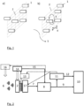
- Fig. 1A shows a simplified schematic representation of an exemplary array 2 of ultrasonic sensors 1.
- the individual ultrasonic sensors 1 can be arranged anywhere within the array 2 or can follow a specific pattern. In the proposed method, this array 2 is moved at least between the individual measurements in order to obtain measurements in different positions and/or orientations of the array 2 relative to the spatial area to be recorded.
- Figure 1B shows, by way of example, different such movements with arrows, in particular a rotation 3, a translation 4 or any movement 5.
- the movement of the array 2 means that most or all of the ultrasonic sensors 1 are in different positions relative to the spatial area to be recorded during the different measurements.
- the movement creates a so-called synthetic aperture, which expands the static aperture and thus provides more information during data acquisition.
- the measurement signals and positions of all measurements are used to generate a sound intensity map with reduced reconstruction artifacts.
- Figure 2 shows a schematic representation of an example of the proposed arrangement for carrying out the method.
- the scene or the spatial area to be observed is indicated by three sound sources 6.
- the arrangement has an array 2 of (air) ultrasound sensors that convert an incoming acoustic sound field from the scene to be observed into electrical measurement signals. These measurement signals are converted into digital measurement signals in a digitization device 17, for example by means of A/D conversion as with conventional ultrasound or by Fourier sampling or other known techniques.
- the digital measurement signals 7 are fed to an imaging device 8, which converts multi-channel electrical measurement signals from the sensor array 2 into a sound intensity map 9. This can be done, for example, using a beamforming method.
- a sound intensity map is understood to be the spatially resolved representation of the strength of the emitted ultrasound.
- the sound intensity map 9 is then displayed in a user-readable form, for example superimposed on a video image of the scene to be observed, by a display unit 10.
- the proposed arrangement preferably also comprises an evaluation unit 11, which extracts information from the sound intensity map 9 that is relevant for the application. In the case of non-destructive testing, this can be, for example, the type, size, depth, etc. of detected defects.
- the evaluation can be carried out, for example, using an image processing algorithm. This information is preferably supplied to the display unit 10 as meta information 12 and is also displayed by it.
- the evaluation unit 10 also provides relevant information about the quality/reliability of the evaluation result and can use this to deduce how future or subsequent measurements should be designed in order to further improve the quality/reliability.
- the evaluation unit determines whether the scene should be viewed from a different position or direction in order to increase the quality or reliability. If necessary, it passes this information on to an actuator 13, which is used for the targeted movement of the sensor array 2.
- the actuator 13 then moves the sensor array 2 according to this specification in order to carry out further measurements at the desired positions or orientations and to include them in the final sound intensity map. This actuator 13 is able to move the sensor array 2 mechanically, i.e. to bring about comprehensible changes in its position (translation) or orientation (rotation/tilting).
- the sensor array 2 is moved manually by the user. Such a movement can also be generated by the natural shaking of the user who is holding the sensor array 2.
- a motion sensor 14 records the current position and location of the sensor array 2 and passes this information on to the imaging device 8. This combines the sequential images from the different viewing angles of the scene to be examined to create the desired sound intensity map 9. For this purpose, the position and/or orientation of the sensor array 2 must be known for each individual measurement. This can be done by the motion sensor 14, for example with the help of inertial sensors, optical tracking (cameras/markers), reference ultrasound transmitters or other techniques. A single viewing angle generally leads to ambiguous results when creating the sound intensity map. Only the combination of several viewing angles makes it possible to clearly resolve the existing defects or sound sources in the scene to be observed. The motion sensor system 14 therefore supplies the position data 15 to the imaging device 8.
- a system 16 for active excitation is also optionally shown.
- This can be an air ultrasound array, a shaker or other devices that can potentially also be controlled by the evaluation unit 11 for recording planning.
- the active excitation can also be carried out by the sensor array 2 itself if it is suitably designed.
- a delay-and-sum method is used as the beamforming algorithm.
- point sources are considered to simplify the description, which emit the acoustic signals s i (t) and are located at the spatial position ( x s,i , y s,i , z s,i ) .
- a i represents the received amplitude (which includes the sound attenuation between source and receiver)
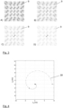
- FIG 4 shows the spiral trajectory 18 along which the array is moved during the measurements.
- the position of the array at frames 0, 1, 11 and 25 is highlighted in the figure.
- the Figures 3A to 3D show the beamforming result at the beginning and after 1, 11 and 25 movement steps.
- the occurrence of artifacts due to spatial subsampling in the first frame ( Figure 3A ) is clearly visible, as is its reduction in the following frames.
- the individual frames are averaged during the evaluation.
- the actual sound sources in the center of the frame are particularly visible in the last frame ( Figure 3D ) clearly visible.
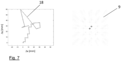
- a suitable evaluation function can, for example, sum up the energy in the previous beamforming intermediate result (provisional sound intensity map) along radial lines and, if necessary, exclude already recognized image areas with relevant information.
- Figure 6 shows an example of how a measure of the artefact strength in different directions can be obtained by summing along radial lines. If the movement is now carried out in such a way that it always occurs along the direction with the strongest artefacts (arrow in the right part of the figure), an automatically selected trajectory 18 results, as shown in Figure 7 for the first 100 frames. In the right part of the Figure 7 The corresponding beamforming result and thus the final sound intensity map when applying this procedure with the optimized trajectory is shown.
- a flexible hardware platform is preferably used that allows the digitization strategy to be adapted to the prior knowledge of the signals to be acquired. This consideration is based on the Fact that signals in these applications typically have certain structures.
- processes are more common that emit considerable signal energy within a narrow ultrasound bandwidth and little to no energy outside of this. These include primarily resonant processes, where the resonance frequency and bandwidth are typical for the size and shape of the phenomenon being observed.
- resonant processes where the resonance frequency and bandwidth are typical for the size and shape of the phenomenon being observed.
- local defect resonance where the relationship between resonance and defect size is derived analytically.
- Narrowband tunable filters are used here, which can be set to individual center frequencies at which signal components are to be expected.
- the complex Fourier coefficients at these frequency support points can thus be measured directly, for example with simple I/Q receiver circuits.
- active excitation can now be used, preferably by suitable control using the evaluation unit, in which sound energy (ultrasound) is coupled into the medium to be examined in the spatial area in a narrow frequency range and the receiver is configured so that it carries out the measurement at the same frequency.
- the selected frequency can now be changed, with the transmitter and receiver moving synchronously in frequency.
- This technique allows resonant phenomena to be measured with very high quality.
- the narrowband excitation and measurement suppresses a significant portion of the unwanted signal components, such as measurement noise. In this way, the amount of data to be recorded for each measurement can be kept small (through direct measurement in the frequency domain), which enables real-time processing.
- the frequency domain representation of the delay-and-sum beamformer can be used directly for this purpose.
- a further embodiment of the digitization device 17 allows flexible decisions, which of the analog channels of the sensor array 2 are selected for digitization (in the sense of a multi-channel switch). This allows the effective array arrangement with which the scene is observed to be changed by switching during the measurement process.
Landscapes
- Physics & Mathematics (AREA)
- General Physics & Mathematics (AREA)
- Immunology (AREA)
- Pathology (AREA)
- Analytical Chemistry (AREA)
- Biochemistry (AREA)
- General Health & Medical Sciences (AREA)
- Life Sciences & Earth Sciences (AREA)
- Health & Medical Sciences (AREA)
- Chemical & Material Sciences (AREA)
- Acoustics & Sound (AREA)
- Engineering & Computer Science (AREA)
- Radar, Positioning & Navigation (AREA)
- Remote Sensing (AREA)
- Computer Networks & Wireless Communication (AREA)
- Measurement Of Velocity Or Position Using Acoustic Or Ultrasonic Waves (AREA)
- Investigating Or Analyzing Materials By The Use Of Ultrasonic Waves (AREA)
Claims (15)
- Procédé pour la détection spatialement résolue des émissions sonores dans une zone spatiale, notamment pour l'essai sans contact de pièces ou la surveillance de processus, comportant un réseau (2) de plusieurs capteurs sonores (1), notamment des capteurs à ultrasons, dans lequel- des signaux sonores émanant de la zone spatiale sont reçus d'une première mesure avec le réseau (2), dans lequel les capteurs sonores (1) sont situés à des premières positions par rapport à la zone spatiale,- une ou plusieurs autres mesures sont effectuées avec le réseau (2) de capteurs sonores (1), dans lequel les capteurs sonores (1) sont disposés à d'autres positions par rapport à la zone spatiale, dont au moins une ne correspond pas aux premières positions, et- les signaux sonores reçus lors de la première mesure et une ou plusieurs autres mesures sont évalués ensemble pour créer une carte d'intensité sonore résolue spatialement (9),caractérisé en ce que
la carte d'intensité sonore est évaluée pour déterminer si elle est encore ambiguë, dans lequel sur la base de cette évaluation une ou plusieurs autres positions ou orientations du son sont déterminées, pour obtenir un résultat plus clair ou au moins plus fiable. - Procédé selon la revendication 1,
caractérisé en ce
qu'une ou plusieurs des autres positions qui ne correspondent pas aux premières positions, peuvent être choisies de sorte à ce qu'elles se trouvent à l'intérieur d'une coque convexe, qui s'étend sur les premières positions. - Procédé selon la revendication 1 ou 2,
caractérisé en ce que
le réseau (2) de capteurs sonores (1) est déplacé pendant la détection, dans lequel la ou les autres mesures ont lieu pendant le mouvement. - Procédé selon la revendication 3,
caractérisé en ce que
le mouvement est effectué manuellement par un utilisateur et un changement de position relative et/ou d'orientation du réseau (2) est détecté par des capteurs sonores (1) entre la première mesure et la ou les autres mesures. - Procédé selon la revendication 3,
caractérisé en ce que
le déplacement s'effectue avec un actionneur (13) et un changement de position relative et/ou d'orientation du réseau (2) de capteurs sonores (1) est enregistré entre la première mesure et la ou les autres mesures. - Procédé selon la revendication 5,
caractérisé en ce quesur la base de l'évaluation de la carte d'intensité sonore (9) les positions supplémentaires et/ou les orientations du réseau (2) de capteurs sonores (1) sont déterminées pour une ou plusieurs mesures supplémentaires, par l'intermédiaire desquelles les artefacts encore présents dans la carte d'intensité sonore (9) sont davantage réduits,l'actionneur (13) pour déplacer le réseau (2) est commandé vers ou dans les positions et/ou orientations supplémentaires et la ou les mesures complémentaires sont effectuées, dans lequel la carte d'intensité sonore (9) est mise à jour en évaluant les signaux sonores reçus lors de la ou des mesures supplémentaires. - Procédé selon la revendication 4,
caractérisé en cequ'à partir de l'évaluation de la carte d'intensité sonore (9), des positions et/ou orientations supplémentaires du réseau (2) de capteurs sonores (1) sont déterminées pour une ou plusieurs mesures supplémentaires, par l'intermédiaire desquelles les artefacts encore présents dans la carte d'intensité sonore (9) sont davantage réduits,l'utilisateur est guidé visuellement et/ou acoustiquement pour déplacer le réseau (2) vers ou dans les positions et/ou orientations supplémentaires, dans lequel la carte d'intensité sonore (9) est mise à jour en évaluant les signaux sonores reçus lors de la ou des mesures supplémentaires. - Procédé selon une des revendications 1 à 7,
caractérisé en ce que
sur la base d'une évaluation de la carte d'intensité sonore (9) ou des signaux sonores reçus un prétraitement des signaux sonores reçus est commandé de telle sorte que seules les plages de fréquences pertinentes pour la détection des émissions sonores de la zone spatiale soient traitées. - Procédé selon une des revendications 1 à 8,
caractérisé en ce que
pour générer les émissions sonores hors de la zone spatiale du son actif, notamment des ultrasons, sont irradiés dans la zone spatiale, dans lequel sur la base d'une évaluation de la carte d'intensité sonore (9) au besoin une adaptation des propriétés, notamment en fréquence et/ou bande passante de fréquence du son irradié activement est effectuée, afin de mieux détecter certains effets, et après l'adaptation, une ou plusieurs mesures supplémentaires sont effectuées afin de mettre à jour la carte d'intensité sonore (9) avec les mesure supplémentaires. - Procédé selon la revendication 9,
caractérisé en ce
qu'un dispositif de numérisation (17) employé pour convertir les signaux sonores reçus en données de mesure numériques est commandé de sorte appropriée pour convertir les signaux sonores reçus en fonction des propriétés, en particulier de la fréquence et/ou de la bande passante de fréquence du son irradié activement. - Procédé selon une des revendications 1 à 10,
caractérisé en ce que
pour générer les émissions sonores hors de la zone spatiale du son actif, notamment des ultrasons, est irradié avec une source sonore ou un réseau de sources sonores dans la zone spatiale, dans lequel la source sonore ou le réseau de sources sonores est déplacé par rapport à la zone spatiale entre les mesures. - Procédé selon une des revendications 1 à 11,
caractérisé en ce que
des transducteurs à ultrasons aériens sont utilisés comme capteurs sonores (1), qui peuvent également émettre des signaux ultrasonores. - Agencement pour la détection spatialement résolue d'émissions d'ultrasons provenant d'une zone spatiale en utilisant le procédé selon une ou plusieurs des revendications précédentes, qui présente- un réseau (2) de plusieurs capteurs sonores (1), notamment des capteurs à ultrasons, avec lesquels des signaux sonores, en particulier des signaux ultrasoniques, provenant de la zone spatiale peuvent être reçus,- un dispositif de numérisation (17) pour convertir des signaux sonores reçus en données de mesure numériques,- un dispositif d'imagerie (8), qui à partir des données de mesure numériques peut générer plusieurs mesures de position et/ou orientations du réseau (2) différentes par rapport à une carte d'intensité sonore (9) résolue spatialement de la zone spatiale,- une unité d'évaluation (11) pour évaluer des informations pertinentes provenant de la carte d'intensité sonore (9) et- un système d'actionneur (13) pour le mouvement contrôlé du réseau (2) à partir de plusieurs capteurs sonores (1),caractérisé en ce quel'unité d'évaluation (11) est conçue de telle sorte que, sur la base d'une évaluation de la carte d'intensité sonore (9), si celle-ci est encore ambiguë, elle détermine des positions et/ou orientations supplémentaires du réseau (2) de capteurs sonores (1) pour une ou plusieurs mesures supplémentaires, par l'intermédiaire desquelles les artefacts encore présents dans la carte d'intensité sonore (9) sont davantage réduits,commande l'actionneur (13) pour déplacer le réseau (2) vers ou dans les positions et/ou orientations supplémentaires et le réseau pour effectuer la ou les mesures supplémentaires, dans lequel la carte d'intensité sonore (9) est mise à jour en évaluant les signaux sonores reçus pendant une ou plusieurs mesures supplémentaires.
- Agencement selon la revendication 13,
caractérisé en ce que
l'unité d'évaluation (11) est conçue de manière à commander, sur la base d'une évaluation de la carte d'intensité sonore (9) ou des signaux sonores reçus, le dispositif de numérisation (17) en vue du prétraitement des signaux sonores reçus de telle sorte que seules les plages de fréquences pertinentes pour la détection des émissions sonores de la zone spatiale soient traitées. - Agencement selon une des revendications 13 ou 14,
caractérisé en ce
qu'il comporte un système de capteurs de mouvement (14) avec lequel un changement de position relative et/ou d'orientation du réseau (2) peut être détecté à partir des capteurs sonores (1) entre des mesures à différentes positions et/ou orientations du réseau (2) par rapport à la zone spatiale.
Applications Claiming Priority (1)
| Application Number | Priority Date | Filing Date | Title |
|---|---|---|---|
| DE102019114756 | 2019-06-03 |
Publications (2)
| Publication Number | Publication Date |
|---|---|
| EP3748397A1 EP3748397A1 (fr) | 2020-12-09 |
| EP3748397B1 true EP3748397B1 (fr) | 2024-08-07 |
Family
ID=68916308
Family Applications (1)
| Application Number | Title | Priority Date | Filing Date |
|---|---|---|---|
| EP19215886.3A Active EP3748397B1 (fr) | 2019-06-03 | 2019-12-13 | Procédé et dispositif de détection résolue localement des émissions sonores, en particulier des émissions ultrasonores |
Country Status (1)
| Country | Link |
|---|---|
| EP (1) | EP3748397B1 (fr) |
Families Citing this family (3)
| Publication number | Priority date | Publication date | Assignee | Title |
|---|---|---|---|---|
| CN113030671B (zh) * | 2021-04-23 | 2022-06-07 | 应急管理部沈阳消防研究所 | 一种电气设备局部放电故障现场检测与定位装置及方法 |
| CN116331298B (zh) * | 2021-12-23 | 2026-01-09 | 比亚迪股份有限公司 | 检测站台屏蔽门与车门之间间隙异物的方法和监控系统 |
| CN114913660B (zh) * | 2022-04-27 | 2024-03-29 | 应急管理部沈阳消防研究所 | 预制舱式电化学储能系统火灾监测、预警及定位装置 |
Family Cites Families (3)
| Publication number | Priority date | Publication date | Assignee | Title |
|---|---|---|---|---|
| EP0883860B1 (fr) * | 1996-02-29 | 2006-08-23 | Acuson Corporation | Systeme, procede et tansducteur d'alignement d'images ultrasonores multiples |
| US6423004B1 (en) * | 2000-05-30 | 2002-07-23 | Ge Medical Systems Global Technology Company, Llc | Real-time ultrasound spatial compounding using multiple angles of view |
| DE102014218364A1 (de) * | 2014-09-12 | 2016-03-17 | Robert Bosch Gmbh | Handmessgerät und Verfahren zu dessen Betrieb |
-
2019
- 2019-12-13 EP EP19215886.3A patent/EP3748397B1/fr active Active
Also Published As
| Publication number | Publication date |
|---|---|
| EP3748397A1 (fr) | 2020-12-09 |
Similar Documents
| Publication | Publication Date | Title |
|---|---|---|
| EP1979739B1 (fr) | Procede d'examen non destructif d'une eprouvette dont au moins une region est constituee d'un materiau acoustiquement anisotrope | |
| EP1943508B1 (fr) | Procede pour examiner un corps d'essai de maniere non destructrice au moyen d'ultrasons | |
| DE10262408B3 (de) | Blockschalten bei Ultraschallabbildung | |
| DE60222476T2 (de) | Ultraschallwandler | |
| DE19843219B4 (de) | Verfahren und Einrichtung zur Ultraschall-Bündelformung mit räumlich codierten Sendungen | |
| EP3748397B1 (fr) | Procédé et dispositif de détection résolue localement des émissions sonores, en particulier des émissions ultrasonores | |
| DE102009047317A1 (de) | Verfahren und Vorrichtung zur Ultraschallprüfung | |
| DE3104014A1 (de) | "ultraschall-abtaster" | |
| DE10050232A1 (de) | Hochauflösender Ultraschalltomograph | |
| WO2009053153A1 (fr) | Procédé et dispositif pour le contrôle non destructif du matériau d'un objet à l'aide d'ondes ultrasonores | |
| DE60215406T2 (de) | Verfahren und Vorrichtung zur Ultraschallabbildung | |
| DE102016100367A1 (de) | Spärliche Verfolgung in Schallstrahlintensitätsimpuls-Bildgebung | |
| EP2898322B1 (fr) | Procédé et dispositif d'amélioration d'une analyse saft en cas de densité de mesures locale irrégulière | |
| EP2992321B1 (fr) | Procédé et dispositif pour l'evaluation des defauts par saft (synthetic aperture focussing technique) | |
| EP2120045A1 (fr) | Dispositif et procédé destinés à la production d'une image à ultrasons par un reseau en phase | |
| EP2032978A1 (fr) | Appareil de contrôle ultrasonore muni de têtes de contrôle à réseau | |
| DE102012112121B4 (de) | Verfahren und Vorrichtung zur zerstörungsfreien Prüfung eines rotationssymmetrischen Werkstücks, welches Abschnitte verschiedener Durchmesser aufweist | |
| EP1943509B1 (fr) | Procede et dispositif pour examiner une piece a usiner tridimensionnelle, aux ultrasons, par imagerie | |
| DE102013004924B4 (de) | Bildgebungssystem und -verfahren | |
| DE10248747B4 (de) | Breitstrahlabbildung | |
| DE112020002488T5 (de) | Muskelbildgebungssystem | |
| DE102012112120B4 (de) | Verfahren und Vorrichtung zur oberflächennahen zerstörungsfreien Prüfung eines rotationssymmetrischen Werkstücks mit abschnittsweise wechselndem Durchmesser mittels Ultraschall | |
| DE102013107816A1 (de) | Ultraschallvorrichtung und Verfahren zum Betreiben einer Ultraschallvorrichtung | |
| DE102012109257B4 (de) | Verfahren und Vorrichtung zur Erzeugung eines Ultraschallbildes | |
| DE4416829A1 (de) | Verfahren und Einrichtung zur Erstellung eines Ultraschall-Tomogramms für einen Querschnitt eines Prüfkörpers |
Legal Events
| Date | Code | Title | Description |
|---|---|---|---|
| PUAI | Public reference made under article 153(3) epc to a published international application that has entered the european phase |
Free format text: ORIGINAL CODE: 0009012 |
|
| STAA | Information on the status of an ep patent application or granted ep patent |
Free format text: STATUS: THE APPLICATION HAS BEEN PUBLISHED |
|
| AK | Designated contracting states |
Kind code of ref document: A1 Designated state(s): AL AT BE BG CH CY CZ DE DK EE ES FI FR GB GR HR HU IE IS IT LI LT LU LV MC MK MT NL NO PL PT RO RS SE SI SK SM TR |
|
| AX | Request for extension of the european patent |
Extension state: BA ME |
|
| STAA | Information on the status of an ep patent application or granted ep patent |
Free format text: STATUS: REQUEST FOR EXAMINATION WAS MADE |
|
| 17P | Request for examination filed |
Effective date: 20210604 |
|
| RBV | Designated contracting states (corrected) |
Designated state(s): AL AT BE BG CH CY CZ DE DK EE ES FI FR GB GR HR HU IE IS IT LI LT LU LV MC MK MT NL NO PL PT RO RS SE SI SK SM TR |
|
| RAP3 | Party data changed (applicant data changed or rights of an application transferred) |
Owner name: TECHNISCHE UNIVERSITAET ILMENAU Owner name: FRAUNHOFER-GESELLSCHAFT ZUR FOERDERUNG DER ANGEWANDTEN FORSCHUNG E.V. |
|
| STAA | Information on the status of an ep patent application or granted ep patent |
Free format text: STATUS: EXAMINATION IS IN PROGRESS |
|
| 17Q | First examination report despatched |
Effective date: 20220830 |
|
| GRAP | Despatch of communication of intention to grant a patent |
Free format text: ORIGINAL CODE: EPIDOSNIGR1 |
|
| STAA | Information on the status of an ep patent application or granted ep patent |
Free format text: STATUS: GRANT OF PATENT IS INTENDED |
|
| RIC1 | Information provided on ipc code assigned before grant |
Ipc: G01S 15/89 20060101ALN20240215BHEP Ipc: G01S 3/808 20060101ALI20240215BHEP Ipc: G01N 29/42 20060101ALI20240215BHEP Ipc: G01N 29/32 20060101ALI20240215BHEP Ipc: G01N 29/14 20060101ALI20240215BHEP Ipc: G01N 29/06 20060101ALI20240215BHEP Ipc: G01N 29/04 20060101ALI20240215BHEP Ipc: G01S 7/52 20060101AFI20240215BHEP |
|
| RIC1 | Information provided on ipc code assigned before grant |
Ipc: G01S 15/89 20060101ALN20240216BHEP Ipc: G01S 3/808 20060101ALI20240216BHEP Ipc: G01N 29/42 20060101ALI20240216BHEP Ipc: G01N 29/32 20060101ALI20240216BHEP Ipc: G01N 29/14 20060101ALI20240216BHEP Ipc: G01N 29/06 20060101ALI20240216BHEP Ipc: G01N 29/04 20060101ALI20240216BHEP Ipc: G01S 7/52 20060101AFI20240216BHEP |
|
| INTG | Intention to grant announced |
Effective date: 20240306 |
|
| GRAS | Grant fee paid |
Free format text: ORIGINAL CODE: EPIDOSNIGR3 |
|
| GRAA | (expected) grant |
Free format text: ORIGINAL CODE: 0009210 |
|
| STAA | Information on the status of an ep patent application or granted ep patent |
Free format text: STATUS: THE PATENT HAS BEEN GRANTED |
|
| P01 | Opt-out of the competence of the unified patent court (upc) registered |
Free format text: CASE NUMBER: APP_35821/2024 Effective date: 20240614 |
|
| REG | Reference to a national code |
Ref country code: DE Ref legal event code: R081 Ref document number: 502019011827 Country of ref document: DE Owner name: TECHNISCHE UNIVERSITAET ILMENAU, KOERPERSCHAFT, DE Free format text: FORMER OWNER: ANMELDERANGABEN UNKLAR / UNVOLLSTAENDIG, 80297 MUENCHEN, DE Ref country code: DE Ref legal event code: R081 Ref document number: 502019011827 Country of ref document: DE Owner name: FRAUNHOFER-GESELLSCHAFT ZUR FOERDERUNG DER ANG, DE Free format text: FORMER OWNER: ANMELDERANGABEN UNKLAR / UNVOLLSTAENDIG, 80297 MUENCHEN, DE |
|
| AK | Designated contracting states |
Kind code of ref document: B1 Designated state(s): AL AT BE BG CH CY CZ DE DK EE ES FI FR GB GR HR HU IE IS IT LI LT LU LV MC MK MT NL NO PL PT RO RS SE SI SK SM TR |
|
| REG | Reference to a national code |
Ref country code: GB Ref legal event code: FG4D Free format text: NOT ENGLISH |
|
| REG | Reference to a national code |
Ref country code: CH Ref legal event code: EP |
|
| REG | Reference to a national code |
Ref country code: DE Ref legal event code: R081 Ref document number: 502019011827 Country of ref document: DE Owner name: TECHNISCHE UNIVERSITAET ILMENAU, KOERPERSCHAFT, DE Free format text: FORMER OWNERS: FRAUNHOFER-GESELLSCHAFT ZUR FOERDERUNG DER ANGEWANDTEN FORSCHUNG E.V., 80686 MUENCHEN, DE; TECHNISCHE UNIVERSITAET ILMENAU, KOERPERSCHAFT DES OEFFENTLICHEN RECHTS, 98693 ILMENAU, DE Ref country code: DE Ref legal event code: R081 Ref document number: 502019011827 Country of ref document: DE Owner name: FRAUNHOFER-GESELLSCHAFT ZUR FOERDERUNG DER ANG, DE Free format text: FORMER OWNERS: FRAUNHOFER-GESELLSCHAFT ZUR FOERDERUNG DER ANGEWANDTEN FORSCHUNG E.V., 80686 MUENCHEN, DE; TECHNISCHE UNIVERSITAET ILMENAU, KOERPERSCHAFT DES OEFFENTLICHEN RECHTS, 98693 ILMENAU, DE |
|
| REG | Reference to a national code |
Ref country code: IE Ref legal event code: FG4D Free format text: LANGUAGE OF EP DOCUMENT: GERMAN |
|
| REG | Reference to a national code |
Ref country code: DE Ref legal event code: R096 Ref document number: 502019011827 Country of ref document: DE |
|
| REG | Reference to a national code |
Ref country code: LT Ref legal event code: MG9D |
|
| REG | Reference to a national code |
Ref country code: NL Ref legal event code: MP Effective date: 20240807 |
|
| PGFP | Annual fee paid to national office [announced via postgrant information from national office to epo] |
Ref country code: DE Payment date: 20241216 Year of fee payment: 6 |
|
| PG25 | Lapsed in a contracting state [announced via postgrant information from national office to epo] |
Ref country code: NO Free format text: LAPSE BECAUSE OF FAILURE TO SUBMIT A TRANSLATION OF THE DESCRIPTION OR TO PAY THE FEE WITHIN THE PRESCRIBED TIME-LIMIT Effective date: 20241107 |
|
| PG25 | Lapsed in a contracting state [announced via postgrant information from national office to epo] |
Ref country code: NL Free format text: LAPSE BECAUSE OF FAILURE TO SUBMIT A TRANSLATION OF THE DESCRIPTION OR TO PAY THE FEE WITHIN THE PRESCRIBED TIME-LIMIT Effective date: 20240807 Ref country code: PT Free format text: LAPSE BECAUSE OF FAILURE TO SUBMIT A TRANSLATION OF THE DESCRIPTION OR TO PAY THE FEE WITHIN THE PRESCRIBED TIME-LIMIT Effective date: 20241209 Ref country code: GR Free format text: LAPSE BECAUSE OF FAILURE TO SUBMIT A TRANSLATION OF THE DESCRIPTION OR TO PAY THE FEE WITHIN THE PRESCRIBED TIME-LIMIT Effective date: 20241108 Ref country code: FI Free format text: LAPSE BECAUSE OF FAILURE TO SUBMIT A TRANSLATION OF THE DESCRIPTION OR TO PAY THE FEE WITHIN THE PRESCRIBED TIME-LIMIT Effective date: 20240807 Ref country code: PL Free format text: LAPSE BECAUSE OF FAILURE TO SUBMIT A TRANSLATION OF THE DESCRIPTION OR TO PAY THE FEE WITHIN THE PRESCRIBED TIME-LIMIT Effective date: 20240807 |
|
| PG25 | Lapsed in a contracting state [announced via postgrant information from national office to epo] |
Ref country code: BG Free format text: LAPSE BECAUSE OF FAILURE TO SUBMIT A TRANSLATION OF THE DESCRIPTION OR TO PAY THE FEE WITHIN THE PRESCRIBED TIME-LIMIT Effective date: 20240807 |
|
| PG25 | Lapsed in a contracting state [announced via postgrant information from national office to epo] |
Ref country code: LV Free format text: LAPSE BECAUSE OF FAILURE TO SUBMIT A TRANSLATION OF THE DESCRIPTION OR TO PAY THE FEE WITHIN THE PRESCRIBED TIME-LIMIT Effective date: 20240807 |
|
| PG25 | Lapsed in a contracting state [announced via postgrant information from national office to epo] |
Ref country code: IS Free format text: LAPSE BECAUSE OF FAILURE TO SUBMIT A TRANSLATION OF THE DESCRIPTION OR TO PAY THE FEE WITHIN THE PRESCRIBED TIME-LIMIT Effective date: 20241207 |
|
| PG25 | Lapsed in a contracting state [announced via postgrant information from national office to epo] |
Ref country code: HR Free format text: LAPSE BECAUSE OF FAILURE TO SUBMIT A TRANSLATION OF THE DESCRIPTION OR TO PAY THE FEE WITHIN THE PRESCRIBED TIME-LIMIT Effective date: 20240807 |
|
| PG25 | Lapsed in a contracting state [announced via postgrant information from national office to epo] |
Ref country code: RS Free format text: LAPSE BECAUSE OF FAILURE TO SUBMIT A TRANSLATION OF THE DESCRIPTION OR TO PAY THE FEE WITHIN THE PRESCRIBED TIME-LIMIT Effective date: 20241107 Ref country code: ES Free format text: LAPSE BECAUSE OF FAILURE TO SUBMIT A TRANSLATION OF THE DESCRIPTION OR TO PAY THE FEE WITHIN THE PRESCRIBED TIME-LIMIT Effective date: 20240807 |
|
| PG25 | Lapsed in a contracting state [announced via postgrant information from national office to epo] |
Ref country code: RS Free format text: LAPSE BECAUSE OF FAILURE TO SUBMIT A TRANSLATION OF THE DESCRIPTION OR TO PAY THE FEE WITHIN THE PRESCRIBED TIME-LIMIT Effective date: 20241107 Ref country code: PT Free format text: LAPSE BECAUSE OF FAILURE TO SUBMIT A TRANSLATION OF THE DESCRIPTION OR TO PAY THE FEE WITHIN THE PRESCRIBED TIME-LIMIT Effective date: 20241209 Ref country code: PL Free format text: LAPSE BECAUSE OF FAILURE TO SUBMIT A TRANSLATION OF THE DESCRIPTION OR TO PAY THE FEE WITHIN THE PRESCRIBED TIME-LIMIT Effective date: 20240807 Ref country code: NO Free format text: LAPSE BECAUSE OF FAILURE TO SUBMIT A TRANSLATION OF THE DESCRIPTION OR TO PAY THE FEE WITHIN THE PRESCRIBED TIME-LIMIT Effective date: 20241107 Ref country code: NL Free format text: LAPSE BECAUSE OF FAILURE TO SUBMIT A TRANSLATION OF THE DESCRIPTION OR TO PAY THE FEE WITHIN THE PRESCRIBED TIME-LIMIT Effective date: 20240807 Ref country code: LV Free format text: LAPSE BECAUSE OF FAILURE TO SUBMIT A TRANSLATION OF THE DESCRIPTION OR TO PAY THE FEE WITHIN THE PRESCRIBED TIME-LIMIT Effective date: 20240807 Ref country code: IS Free format text: LAPSE BECAUSE OF FAILURE TO SUBMIT A TRANSLATION OF THE DESCRIPTION OR TO PAY THE FEE WITHIN THE PRESCRIBED TIME-LIMIT Effective date: 20241207 Ref country code: HR Free format text: LAPSE BECAUSE OF FAILURE TO SUBMIT A TRANSLATION OF THE DESCRIPTION OR TO PAY THE FEE WITHIN THE PRESCRIBED TIME-LIMIT Effective date: 20240807 Ref country code: GR Free format text: LAPSE BECAUSE OF FAILURE TO SUBMIT A TRANSLATION OF THE DESCRIPTION OR TO PAY THE FEE WITHIN THE PRESCRIBED TIME-LIMIT Effective date: 20241108 Ref country code: FI Free format text: LAPSE BECAUSE OF FAILURE TO SUBMIT A TRANSLATION OF THE DESCRIPTION OR TO PAY THE FEE WITHIN THE PRESCRIBED TIME-LIMIT Effective date: 20240807 Ref country code: ES Free format text: LAPSE BECAUSE OF FAILURE TO SUBMIT A TRANSLATION OF THE DESCRIPTION OR TO PAY THE FEE WITHIN THE PRESCRIBED TIME-LIMIT Effective date: 20240807 Ref country code: BG Free format text: LAPSE BECAUSE OF FAILURE TO SUBMIT A TRANSLATION OF THE DESCRIPTION OR TO PAY THE FEE WITHIN THE PRESCRIBED TIME-LIMIT Effective date: 20240807 |
|
| PG25 | Lapsed in a contracting state [announced via postgrant information from national office to epo] |
Ref country code: DK Free format text: LAPSE BECAUSE OF FAILURE TO SUBMIT A TRANSLATION OF THE DESCRIPTION OR TO PAY THE FEE WITHIN THE PRESCRIBED TIME-LIMIT Effective date: 20240807 Ref country code: RO Free format text: LAPSE BECAUSE OF FAILURE TO SUBMIT A TRANSLATION OF THE DESCRIPTION OR TO PAY THE FEE WITHIN THE PRESCRIBED TIME-LIMIT Effective date: 20240807 Ref country code: SM Free format text: LAPSE BECAUSE OF FAILURE TO SUBMIT A TRANSLATION OF THE DESCRIPTION OR TO PAY THE FEE WITHIN THE PRESCRIBED TIME-LIMIT Effective date: 20240807 |
|
| PG25 | Lapsed in a contracting state [announced via postgrant information from national office to epo] |
Ref country code: EE Free format text: LAPSE BECAUSE OF FAILURE TO SUBMIT A TRANSLATION OF THE DESCRIPTION OR TO PAY THE FEE WITHIN THE PRESCRIBED TIME-LIMIT Effective date: 20240807 |
|
| PGFP | Annual fee paid to national office [announced via postgrant information from national office to epo] |
Ref country code: CH Payment date: 20250101 Year of fee payment: 6 |
|
| PG25 | Lapsed in a contracting state [announced via postgrant information from national office to epo] |
Ref country code: CZ Free format text: LAPSE BECAUSE OF FAILURE TO SUBMIT A TRANSLATION OF THE DESCRIPTION OR TO PAY THE FEE WITHIN THE PRESCRIBED TIME-LIMIT Effective date: 20240807 |
|
| PG25 | Lapsed in a contracting state [announced via postgrant information from national office to epo] |
Ref country code: SK Free format text: LAPSE BECAUSE OF FAILURE TO SUBMIT A TRANSLATION OF THE DESCRIPTION OR TO PAY THE FEE WITHIN THE PRESCRIBED TIME-LIMIT Effective date: 20240807 |
|
| REG | Reference to a national code |
Ref country code: DE Ref legal event code: R097 Ref document number: 502019011827 Country of ref document: DE |
|
| PLBE | No opposition filed within time limit |
Free format text: ORIGINAL CODE: 0009261 |
|
| STAA | Information on the status of an ep patent application or granted ep patent |
Free format text: STATUS: NO OPPOSITION FILED WITHIN TIME LIMIT |
|
| PG25 | Lapsed in a contracting state [announced via postgrant information from national office to epo] |
Ref country code: MC Free format text: LAPSE BECAUSE OF FAILURE TO SUBMIT A TRANSLATION OF THE DESCRIPTION OR TO PAY THE FEE WITHIN THE PRESCRIBED TIME-LIMIT Effective date: 20240807 |
|
| 26N | No opposition filed |
Effective date: 20250508 |
|
| PG25 | Lapsed in a contracting state [announced via postgrant information from national office to epo] |
Ref country code: LU Free format text: LAPSE BECAUSE OF NON-PAYMENT OF DUE FEES Effective date: 20241213 |
|
| GBPC | Gb: european patent ceased through non-payment of renewal fee |
Effective date: 20241213 |
|
| PG25 | Lapsed in a contracting state [announced via postgrant information from national office to epo] |
Ref country code: SE Free format text: LAPSE BECAUSE OF FAILURE TO SUBMIT A TRANSLATION OF THE DESCRIPTION OR TO PAY THE FEE WITHIN THE PRESCRIBED TIME-LIMIT Effective date: 20240807 |
|
| REG | Reference to a national code |
Ref country code: BE Ref legal event code: MM Effective date: 20241231 |
|
| PG25 | Lapsed in a contracting state [announced via postgrant information from national office to epo] |
Ref country code: GB Free format text: LAPSE BECAUSE OF NON-PAYMENT OF DUE FEES Effective date: 20241213 Ref country code: BE Free format text: LAPSE BECAUSE OF NON-PAYMENT OF DUE FEES Effective date: 20241231 |
|
| PG25 | Lapsed in a contracting state [announced via postgrant information from national office to epo] |
Ref country code: IE Free format text: LAPSE BECAUSE OF NON-PAYMENT OF DUE FEES Effective date: 20241213 |
|
| REG | Reference to a national code |
Ref country code: CH Ref legal event code: U11 Free format text: ST27 STATUS EVENT CODE: U-0-0-U10-U11 (AS PROVIDED BY THE NATIONAL OFFICE) Effective date: 20260101 |
|
| PGFP | Annual fee paid to national office [announced via postgrant information from national office to epo] |
Ref country code: AT Payment date: 20251215 Year of fee payment: 7 |
|
| PGFP | Annual fee paid to national office [announced via postgrant information from national office to epo] |
Ref country code: FR Payment date: 20251218 Year of fee payment: 7 |
|
| PG25 | Lapsed in a contracting state [announced via postgrant information from national office to epo] |
Ref country code: IT Free format text: LAPSE BECAUSE OF FAILURE TO SUBMIT A TRANSLATION OF THE DESCRIPTION OR TO PAY THE FEE WITHIN THE PRESCRIBED TIME-LIMIT Effective date: 20240807 |