EP3748272B1 - Hybridrohrbündelverdampfer - Google Patents
Hybridrohrbündelverdampfer Download PDFInfo
- Publication number
- EP3748272B1 EP3748272B1 EP20175901.6A EP20175901A EP3748272B1 EP 3748272 B1 EP3748272 B1 EP 3748272B1 EP 20175901 A EP20175901 A EP 20175901A EP 3748272 B1 EP3748272 B1 EP 3748272B1
- Authority
- EP
- European Patent Office
- Prior art keywords
- shell
- evaporator
- tubes
- tube bundle
- refrigerant fluid
- Prior art date
- Legal status (The legal status is an assumption and is not a legal conclusion. Google has not performed a legal analysis and makes no representation as to the accuracy of the status listed.)
- Active
Links
- 239000012530 fluid Substances 0.000 claims description 78
- 239000003507 refrigerant Substances 0.000 claims description 52
- 238000005192 partition Methods 0.000 claims description 18
- 239000007788 liquid Substances 0.000 claims description 13
- 238000005057 refrigeration Methods 0.000 claims description 8
- 230000000630 rising effect Effects 0.000 claims description 5
- 230000006835 compression Effects 0.000 claims description 4
- 238000007906 compression Methods 0.000 claims description 4
- 238000009826 distribution Methods 0.000 description 25
- 239000007792 gaseous phase Substances 0.000 description 14
- 238000000034 method Methods 0.000 description 13
- 230000008569 process Effects 0.000 description 13
- 230000037361 pathway Effects 0.000 description 9
- 230000005484 gravity Effects 0.000 description 5
- 239000007791 liquid phase Substances 0.000 description 5
- 239000011552 falling film Substances 0.000 description 3
- 238000001816 cooling Methods 0.000 description 2
- 238000003698 laser cutting Methods 0.000 description 2
- 239000003595 mist Substances 0.000 description 2
- 230000003287 optical effect Effects 0.000 description 2
- 230000000750 progressive effect Effects 0.000 description 2
- 238000006424 Flood reaction Methods 0.000 description 1
- 230000015572 biosynthetic process Effects 0.000 description 1
- 238000010276 construction Methods 0.000 description 1
- 238000010924 continuous production Methods 0.000 description 1
- 230000001419 dependent effect Effects 0.000 description 1
- 230000000694 effects Effects 0.000 description 1
- 230000003993 interaction Effects 0.000 description 1
- 238000012986 modification Methods 0.000 description 1
- 230000004048 modification Effects 0.000 description 1
- 239000012071 phase Substances 0.000 description 1
- 239000002244 precipitate Substances 0.000 description 1
- 239000007921 spray Substances 0.000 description 1
- 230000003068 static effect Effects 0.000 description 1
- 238000003786 synthesis reaction Methods 0.000 description 1
Images


Classifications
-
- F—MECHANICAL ENGINEERING; LIGHTING; HEATING; WEAPONS; BLASTING
- F28—HEAT EXCHANGE IN GENERAL
- F28D—HEAT-EXCHANGE APPARATUS, NOT PROVIDED FOR IN ANOTHER SUBCLASS, IN WHICH THE HEAT-EXCHANGE MEDIA DO NOT COME INTO DIRECT CONTACT
- F28D7/00—Heat-exchange apparatus having stationary tubular conduit assemblies for both heat-exchange media, the media being in contact with different sides of a conduit wall
- F28D7/16—Heat-exchange apparatus having stationary tubular conduit assemblies for both heat-exchange media, the media being in contact with different sides of a conduit wall the conduits being arranged in parallel spaced relation
- F28D7/163—Heat-exchange apparatus having stationary tubular conduit assemblies for both heat-exchange media, the media being in contact with different sides of a conduit wall the conduits being arranged in parallel spaced relation with conduit assemblies having a particular shape, e.g. square or annular; with assemblies of conduits having different geometrical features; with multiple groups of conduits connected in series or parallel and arranged inside common casing
-
- F—MECHANICAL ENGINEERING; LIGHTING; HEATING; WEAPONS; BLASTING
- F25—REFRIGERATION OR COOLING; COMBINED HEATING AND REFRIGERATION SYSTEMS; HEAT PUMP SYSTEMS; MANUFACTURE OR STORAGE OF ICE; LIQUEFACTION SOLIDIFICATION OF GASES
- F25B—REFRIGERATION MACHINES, PLANTS OR SYSTEMS; COMBINED HEATING AND REFRIGERATION SYSTEMS; HEAT PUMP SYSTEMS
- F25B39/00—Evaporators; Condensers
- F25B39/02—Evaporators
-
- F—MECHANICAL ENGINEERING; LIGHTING; HEATING; WEAPONS; BLASTING
- F28—HEAT EXCHANGE IN GENERAL
- F28F—DETAILS OF HEAT-EXCHANGE AND HEAT-TRANSFER APPARATUS, OF GENERAL APPLICATION
- F28F25/00—Component parts of trickle coolers
- F28F25/02—Component parts of trickle coolers for distributing, circulating, and accumulating liquid
- F28F25/06—Spray nozzles or spray pipes
-
- F—MECHANICAL ENGINEERING; LIGHTING; HEATING; WEAPONS; BLASTING
- F25—REFRIGERATION OR COOLING; COMBINED HEATING AND REFRIGERATION SYSTEMS; HEAT PUMP SYSTEMS; MANUFACTURE OR STORAGE OF ICE; LIQUEFACTION SOLIDIFICATION OF GASES
- F25B—REFRIGERATION MACHINES, PLANTS OR SYSTEMS; COMBINED HEATING AND REFRIGERATION SYSTEMS; HEAT PUMP SYSTEMS
- F25B2339/00—Details of evaporators; Details of condensers
- F25B2339/02—Details of evaporators
- F25B2339/022—Evaporators constructed from a pair of plates forming a space in which is located a refrigerant carrying coil
-
- F—MECHANICAL ENGINEERING; LIGHTING; HEATING; WEAPONS; BLASTING
- F28—HEAT EXCHANGE IN GENERAL
- F28D—HEAT-EXCHANGE APPARATUS, NOT PROVIDED FOR IN ANOTHER SUBCLASS, IN WHICH THE HEAT-EXCHANGE MEDIA DO NOT COME INTO DIRECT CONTACT
- F28D21/00—Heat-exchange apparatus not covered by any of the groups F28D1/00 - F28D20/00
- F28D2021/0019—Other heat exchangers for particular applications; Heat exchange systems not otherwise provided for
- F28D2021/0068—Other heat exchangers for particular applications; Heat exchange systems not otherwise provided for for refrigerant cycles
- F28D2021/0071—Evaporators
-
- F—MECHANICAL ENGINEERING; LIGHTING; HEATING; WEAPONS; BLASTING
- F28—HEAT EXCHANGE IN GENERAL
- F28F—DETAILS OF HEAT-EXCHANGE AND HEAT-TRANSFER APPARATUS, OF GENERAL APPLICATION
- F28F9/00—Casings; Header boxes; Auxiliary supports for elements; Auxiliary members within casings
- F28F9/22—Arrangements for directing heat-exchange media into successive compartments, e.g. arrangements of guide plates
- F28F2009/222—Particular guide plates, baffles or deflectors, e.g. having particular orientation relative to an elongated casing or conduit
- F28F2009/224—Longitudinal partitions
Definitions
- the present invention refers to an improved hybrid tube bundle evaporator having a low-load and high performance for vapour compression refrigeration circuits.
- tube bundle and shell evaporators for known-type vapour compression refrigeration circuits, constituted substantially by a tube bundle inside a recipient usually having a cylindrical shape with a horizontal axis, usually known as a "shell", and closed at the ends.
- the device is crossed by two fluid currents: a current corresponding to the process fluid, i.e. the fluid that is to be cooled, which flows on the "tube-side", that is, inside the tubes, while the other current corresponds to the service fluid, i.e. the refrigerant fluid used as the vector of the heat exchange and which flows on the "shell-side", i.e. in the space delimited between the inner surface of the shell and the outer surfaces of the tubes; the large outer surfaces of the tubes, generally having a modest diameter and in a large number, enable heat exchange of large quantities of heat.
- the pathway of the tube bundle inside the shell can be straight, with a parallel axis to the longitudinal axis of the evaporator, from an inlet head to the opposite outlet head, or can be straight but with an outward and return pathway over the whole length of the shell, with an inlet and outlet at the same evaporator head; the type depends on the general characteristics of the system and the design choices and expected performances.
- the process that takes place inside an evaporator in a refrigeration circuit is a continuous process, through which the flow of the service refrigerant fluid at a lower temperature subtracts heat from the process fluid flow at a higher temperature, and in turn heats up and changes from the liquid phase to the gaseous phase.
- the flooded type i.e. with the tube bundle completely immersed in the service fluid in the moist phase
- the low-load flooded type in which the service fluid load is reduced coherently with the setting and control of other parameters of the system
- the falling film type in which the tubes are sprinkled by the service refrigerant fluid which falls in cascade
- the spray type where the service refrigerant fluid is sprayed onto the tubes.
- hybrid Another type, known as hybrid, pairs the characteristics of the low-load flooded type with those of the falling film type.
- WO 2011/011421 A2 discloses a horizontal tube bundle evaporator according to the preamble of claim 1.
- the technical task of the present invention is, therefore, to provide a horizontal tube bundle evaporator which obviates the above-described technical drawbacks of the prior art.
- an object of the invention is to realise a tube bundle evaporator of a hybrid type, which unites the characteristics of the low-load flooded type and of the falling film type, thus obviating the drawbacks of both.
- a further aim of the invention is to realise a tube bundle evaporator of a hybrid type which optimises the fluid-dynamics of the service fluid and the heat exchange with the process flow.
- a further aim of the invention is to realise a tube bundle evaporator of a hybrid type from which the service fluid in outlet can be returned to the refrigeration circuit prevalently in the gaseous phase.
- a further aim of the invention is to realise a tube bundle evaporator of a hybrid type which improves the distribution system of the service fluid on the tube bundle.
- a further aim of the invention is to realise a tube bundle evaporator of a hybrid type which optimises the positions of the fittings towards the external devices.
- said conveying circuit comprises a descending portion of circuit delimited by at least one separating primary vertical partition separating a first upper chamber of said evaporator where the second number of tubes is positioned from a second upper lateral chamber of said evaporator where said outlet from the shell is positioned.
- said separating primary vertical partition superiorly separates said first upper chamber and said second upper lateral chamber and extends downwards up to a distance from the free surface of said flooded lower zone for collecting the refrigerant fluid in the liquid state.
- said separating primary vertical partition delimits in cooperation with the free surface of said lower zone a connecting passage between said first upper chamber where said descending portion of circuit extends and said second upper lateral chamber where a rising portion of circuit extends in succession to said descending portion of circuit.
- said second upper lateral chamber contains a third number of tubes of said tube bundle arranged outside said lower zone, said outlet being positioned in said second upper lateral chamber above said third number of tubes.
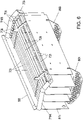
- a horizontal axis hybrid tube bundle evaporator is denoted in its entirety by reference number 1, essentially constituted by a cylindrical shell 2, by two closing heads 3A and 3B, a tube bundle 4 thus identified in its entirety and contained inside the shell 2 where the tubes individually perform an outward and return pathway parallel to the longitudinal horizontal axis and over the whole length of the shell 2, an inlet 5 in a closing head 3A of the process fluid to be cooled and an outlet 6 in a closing head 3A of the cooled process fluid;
- the evaporator 1 further has two inlets 7A and 7B of the service refrigerant fluid in the liquid state in a lower lateral zone of the shell 2, symmetrically arranged in the direction of the longitudinal axis with respect to an outlet 8 of the service refrigerant fluid in the gaseous state positioned in an upper lateral zone of the shell 2, and an optical viewer 9 for controlling the level of the service refrigerant fluid on the lower lateral wall of the shell 2.
- the outlet 8 comprises a through-opening 8A through the thickness of the shell 2, entirely positioned below the upper end of the shell 2 and a fitting tube 8B which prolongs from the through-opening 8A to outside the shell 2 and projects for a terminal portion of the length thereof above the lateral border of the shell 2.
- the fitting tube 8B is angular to connect correctly to the piping of the refrigeration circuit.
- Each inlet 7A, 7B of the service refrigerant fluid in the liquid state comprises a through-opening 7'A, 7'B through the thickness of the shell 2 from which a fitting tube 7"A, 7"B positioned outside the shell 2 but entirely contained inside the lateral border of the shell 2.
- each fitting tube 7"A, 7"B is contained between the horizontal plane tangential to the upper end of the shell 2 and the horizontal plane tangential to the lower end of the shell 2.
- a first number of tubes 41 of the tube bundle 4 is positioned in a lower zone 21 of the evaporator 1 flooded by the service fluid, a second number of tubes 42 is positioned in an upper zone 22 of the evaporator 1 above the first number of tubes 41.
- a distributor 70 of the service refrigerant fluid is positioned in the upper zone 22 of the evaporator 1 above the second number of tubes 42 of the tube bundle 4, and is constituted by two opposite collectors 71A and 71B respectively connected to the inlets 7A and 7B of the refrigerant fluid in the evaporator 1, and mounted with a perpendicular axis to the longitudinal axis of the evaporator 1 and of the tube bundle 4.
- a plurality of straight distribution tubes 72i is perpendicularly connected to both collectors 71A and 71B, by means of respective fittings 73i at the ends thereof, with a longitudinal axis parallel to the axis of the evaporator 1 and the tube bundle 4.
- the tube bundle 4 is supported inside the shell 2 by a plurality of transversal support plates 80i perpendicular to the longitudinal axis of the tubes and the evaporator 1, appropriately perforated for guided and continuous passage of the single tubes and appropriately configured for mounting inside the evaporator 1.
- a further plurality of vertical longitudinal secondary partitions 81i advantageously joint-fixed to the transversal support plates 80i longitudinally divides, into a plurality of sectors, the tubes of the second number of tubes 42 of the tube bundle 4 in the zone 22 of the evaporator 1.
- the transversal support plates 80i further divide the longitudinal sectors into sub-units.
- transversal support plates 80i and the longitudinal partitions 81i have appropriate pluralities of savings and through-openings, respectively 82i and 83i which have the function of equalising the pressure of the refrigerant fluid between these sectors and sub-units inside the evaporator 1.
- a plurality of longitudinal deflecting fins 85i is further fixed on the longitudinal partitions 81i, again with the aim of equalising the flow distribution of the refrigerant fluid by force of gravity on the tubes of the second number of tubes 42.
- a special primary vertical partition 88 longitudinally extended, conjoined at the top thereof to the internal lateral surface of the shell 2 and inferiorly extending downwards up to a suitable distance from the free surface of the flooded lower zone 21 for collecting the refrigerant fluid in the liquid state.
- the primary vertical partition 88 divides the upper zone 22 of the evaporator in which it defines a first upper chamber 23 in which the second number of tubes 42 and the distributor 70 of the service refrigerant fluid are housed, and a second upper lateral chamber 24 of the evaporator 1, towards the side of the shell 2 where the inlets 7A and 7B are located, to which the distributor 70 and the outlet 8 of the refrigerant fluid in the gaseous state are connected.
- a third number of tubes 43 connected via a collector 51 in the head 3A is housed inside the second upper lateral chamber 24 of the evaporator 1.
- the head 3A has the inlet collector 51 connected to the inlet 5 of the process fluid in the evaporator 1, and an outlet collector 61 connected to the outlet 6 of the cooled process fluid; the inlet collector 51 supplies the first number of tubes 41, the third number of tubes 43 and the lower group of tubes of said second number of tubes 42; the outlet collector 61 is supplied by an upper group of tubes of said second number of tubes 42.
- the process fluid to be cooled is introduced into the evaporator 1 through the inlet 5 in the head 3A, and thus in the inlet collector 51 from which it is distributed into the first number of tubes 41, the third number of tubes 43 and the lower group of tubes of the second number of tubes 42.
- the process fluid to be cooled coming from the system circulation and appropriately moved by movement means outside the evaporator, travels through the tubes in a horizontal-axis outward and return pathway inside the evaporator 1 over the whole length of the shell 2.
- the upper group of tubes of the second number of tubes 42 thus returns to the outlet collector 61 in the head 3A, from which the appropriately-cooled process fluid is collected and connected to the outlet 6 from the evaporator 1 and reinjected into the cooling system circulation of which the evaporator is a part.
- the service refrigerant fluid in the liquid state coming from other lines of the cooling system and appropriately moved by movement means outside the evaporator, is injected into the evaporator 1 symmetrically, given equal conditions of temperature and pressure, through the two inlets 7A and 7B positioned in a lower lateral zone of the shell 2 the inside of which corresponds to the second upper lateral chamber 24 of the evaporator 1.
- the two opposite collectors 71A and 71B are respectively connected to the inlets 7A and 7B of the fluid distributor 70 of the service refrigerant fluid, via which collectors and via the successive plurality of fittings 73i derived therefrom, the refrigerant fluid reaches the plurality of distribution tubes 72i from opposite ends.
- the supply of the refrigerant fluid from the collectors 71A and 71B to the opposite ends of the plurality of distribution tubes 72i advantageously guarantees the homogeneity of the temperature and pressure conditions of the refrigerant fluid in each tube and inside each of the tubes of the plurality of distribution tubes 72i.
- the refrigerant fluid locates, in the plurality of distribution tubes 72i, the plurality of lower longitudinal dispensing openings 74i, through which the refrigerant fluid in the liquid state sprinkles the second number of tubes 42 by force of gravity.
- the heat exchange by convection, between the refrigerant flow and the outer walls of the second number of tubes 42 inside which the process fluid flows at a higher temperature causes, among other things, the raising of the temperature of the refrigerant fluid, and a partial passage thereof from the liquid phase to the mixed-gaseous phase ("mist") and to the gaseous phase.
- the refrigerant fluid in its fall by force of gravity from the plurality of lower longitudinal dispensing openings 74i in the plurality of distribution tubes 72i on the second number of tubes 42, is compartmentalised into a plurality of sub-units of a plurality of sectors defined by the plurality of transversal support plates 80i and of the vertical longitudinal partitions 81i.
- the plurality of longitudinal deflecting fins 85i fixed on the longitudinal partitions 81i advantageously facilitates the detachment of the refrigerant fluid that might have accumulated on the longitudinal partitions 81i during the liquid phase and a better and progressive redistribution on the rows of the second number of tubes 42 positioned inferiorly of the longitudinal deflecting fins 85i.
- the plurality of savings and through-openings, respectively 82i and 83i in the transversal support plates 80i and in the longitudinal partitions 81i which are compartmentalised into a plurality of sub-units of a plurality of sectors inside the evaporator 1, advantageously facilitate the uniformity of the distribution of the refrigerant fluid during the progressively gaseous and mixed-gaseous phase in the progressive fall thereof on the rows of the second number of tubes 42.
- the portion of refrigerant fluid still in the liquid phase after having sprayed the second number of tubes 42 by force of gravity, precipitates and is collected in (floods) the lower zone 21 of the evaporator 1, where the first number of tubes 41 of the tube bundle 4 is positioned and where the heat exchange is actuated in a static form by conduction between the refrigerant fluid in the liquid phase and the outer walls of the first number of tubes 41 of the tube bundle 4 which remains completely immersed (flooded) in the fluid.
- the level of the service refrigerant fluid in the flooded lower zone 21 is controlled, which level must be maintained, by an appropriate control and balancing of the functions of the system outside the evaporator 1, at a higher level than the upper horizontal row of the first number of tubes 41 of the tube bundle 4.
- the portion of refrigerant fluid in the gaseous and mixed-gaseous phase, created for the heat exchange realised with interaction of the refrigerant fluid and the second number of tubes 42 in the first upper chamber 23 of the evaporator 1, physically and naturally tending to vertically rise towards the top of the first upper chamber 23, is advantageously aspirated by means of an appropriate depression created by aspirating means outside the evaporator 1 at the outlet 8 from the shell 2, positioned at the upper lateral chamber 24 of the evaporator 1.
- the primary partition 88 in cooperation with the free surface of the collecting flooded lower zone 21, inferiorly delimits a connecting passage between the first upper chamber 23 where a descending portion of circuit extends, and the second upper lateral chamber 24 where a rising portion of circuit extends in succession to a descending portion of circuit of the tortuous pathway of the refrigerant fluid in the gaseous and mixed-gaseous phase.
- the tortuous pathway of the refrigerant fluid in gaseous and mixed-gaseous phase advantageously strikes, in the inversion from descending portion of circuit to rising portion of circuit, the upper horizontal row 44 of tubes of the first number of tubes 41 and thus actuates a heat exchange which tends to reduce the moisture still remaining in the mixed-gaseous phase.
- the third number of tubes 43 is also housed inside the second upper lateral chamber 24 and is arranged at an upper level than the horizontal row of tubes 44, which is further struck by the refrigerant fluid in the gaseous and mixed-gaseous phase in a rising portion of circuit of the tortuous pathway, actuating a further heat exchange which tends to eliminate the moisture still residual in the mixed-gaseous phase (mist).
- the refrigerated service fluid is advantageously thus distanced by the evaporator 1 from the outlet 8 and injected into the circuit of the refrigeration system in prevalently gaseous phase.
- the horizontal evaporator of the invention is characterised in particular by the specific construction of the distributor 70.
- the distributor 70 has a tube distribution system 72i, with the tubes being provided with one or more lower longitudinal openings 74i.
- the lower longitudinal openings 74i preferably extend longitudinally along the lower axial generatrix of the distribution tubes 72i.
- the tubes 72i can be supplied at an end thereof by a single tubular collector or, as has been seen, they can be supplied at both ends by opposite tubular collectors 71, 71B.
- the tubes 72i can have various shapes, dimensions and arrangements.
- the tubes 72i are preferably straight, cylindrical, and are orientated horizontally in the longitudinal direction of the evaporator 1.
- the tubes 72i do not necessarily need to be all positioned at the same height, in particular, to optimise the occupation of the space inside the shell 2, the arrangement of the tubes 72i can be adapted to the internal profile of the shell 2.
- the distribution tubes 72i can be arranged following the internal profile of the shell 2, with the central tubes 72i higher and the lateral tubes 72i gradually lower.
- the distribution tubes 72i can be all of identical transversal dimensions, inside diameter and external diameter in the case of the cylindrical shape.
- the central tubes 72i can have an internal passage section that is greater than the passage section of the lateral tubes 72i and longitudinal openings 74i having a greater area than that of the lateral tubes 72i.
- the distribution tubes 72i can be supported directly by the transversal support plates 80i.
- the transversal support plates 80i can therefore have first support holes of the tube bundle 4 and, above the first holes, second support holes of the distribution tubes 72i.
- the lower longitudinal dispensing openings 74i are preferably fashioned by laser cutting so as to have high dimensional precision.
- the number, shape and dimension of the lower longitudinal dispensing openings 74i can vary.
- the lower longitudinal dispensing openings 74i are straight slots. In an embodiment the lower longitudinal dispensing openings 74i are slots having a constant width.
- the lower longitudinal dispensing openings 74i are slots having a constant length.
- the lower longitudinal dispensing openings 74i are slots having, from the end of the distribution tubes 72i towards the centre of the distribution tubes 72i, a constant width and a progressively increasing length, or a constant length and a progressively increasing width, or a progressively increasing width and length, or an increasing width in the case of a single longitudinal dispensing opening 74i.
- the lower longitudinal dispensing openings 74i are slots having, from the end of the distribution tubes 72i connected to the collector towards the free end of the distribution tubes 72i, a constant width and a progressively increasing length, or a constant length and a progressively increasing width, or a width and a length that are progressively increasing, or an increasing width in the case of a single longitudinal dispensing opening 74i.
- the distribution tubes 71i can project below the lower axial generatrix of the tubular collectors 71A, 71B.
- a hybrid tube bundle evaporator comprising a service refrigerant fluid distributor according to the invention is particularly advantageous for optimising the service fluid distribution on the tube bundle.
Claims (8)
- Rohrbündelverdampfer (1), der sich längs entlang einer horizontalen Achse erstreckt, umfassend einen Mantel (2), ein Rohrbündel (4), das im Mantel untergebracht ist, ein mantelseitiges Kältemittel, ein rohrseitiges Kältemittel, eine untere Zone (21) des Verdampfers (1), die vom Kältemittel im flüssigen Zustand geflutet ist und eine erste Anzahl von Rohren (41) des Rohrbündels (4) enthält, einen Betriebskältemittelverteiler (70), der in einer oberen Zone (22) des Verdampfers (1) positioniert ist, um Kältemittel im flüssigen Zustand durch freien Fall auf eine zweite Anzahl von Rohren (42) des Rohrbündels (4), die außerhalb der unteren Zone (21) über der ersten Anzahl von Rohren (41) positioniert sind, auszugeben, umfassend mindestens einen Auslass (8) von Kältemittel im gasförmigen Zustand, der in einer oberen Seitenzone des Mantels (2) positioniert ist, und einen Förderkreislauf, der im Mantel (2) eingeschlossen ist, um Kältemittel im gasförmigen Zustand hinführend zum mindestens einen oberen Seitenauslass (8) zu befördern, wobei der Förderkreislauf mindestens einen absteigenden Kreislaufabschnitt umfasst, der durch mindestens eine vertikale Haupttrennunterteilung (88) begrenzt ist, die sich längs erstreckt, die an ihrer Oberseite mit der inneren seitlichen Oberfläche des Mantels (2) zusammengefügt ist, trennend eine erste obere Kammer (23) des Verdampfers, in der die zweite Anzahl von Rohren (42) positioniert ist, von einer zweiten oberen Seitenkammer (24) des Verdampfers (1), in der der Auslass (8) aus dem Mantel positioniert ist, dadurch gekennzeichnet, dass die zweite obere Seitenkammer (24) eine dritte Anzahl von Rohren (43) des Rohrbündels (4) enthält, die außerhalb der unteren Zone (21) angeordnet sind, wobei der Auslass (8) in der zweiten oberen Seitenkammer (24) über der dritten Anzahl von Rohren (43) positioniert ist.
- Horizontaler Rohrbündelverdampfer (1) nach einem der vorhergehenden Ansprüche, umfassend mindestens einen Einlass (7A) des Betriebskältemittels im flüssigen Zustand in einer Seitenzone des Mantels (2).
- Horizontaler Rohrbündelverdampfer (1) nach einem der vorhergehenden Ansprüche, wobei der mindestens eine Auslass (8) eine Durchführungsöffnung (8A) durch die Dicke des Mantels (2) umfasst, die vollständig unter dem oberen Ende des Mantels (2) positioniert ist, und ein Rohrformstück (8B), das sich von der Durchführungsöffnung (8A) zur Außenseite des Mantels (2) ausdehnt und um einen Endabschnitt seiner Länge über der Seitenkante des Mantels (2) hervorsteht.
- Horizontaler Rohrbündelverdampfer (1) nach dem vorhergehenden Anspruch, wobei das Rohrformstück (8B) winkelig ist.
- Horizontaler Rohrbündelverdampfer (1) nach einem der Ansprüche 2 bis 4, wobei der mindestens eine Einlass (7A) des Betriebskältemittels im flüssigen Zustand eine Durchführungsöffnung (7'A) durch die Dicke des Mantels (2) umfasst, aus der sich ein Rohrformstück (7"A) ausdehnt, das außerhalb des Mantels (2) positioniert ist, das jedoch vollständig innerhalb der Seitenkante des Mantels (2) enthalten ist.
- Horizontaler Rohrbündelverdampfer (1) nach einem der vorhergehenden Ansprüche, wobei die vertikale Haupttrennunterteilung (88) oberseitig die erste obere Kammer (23) und die zweite obere Seitenkammer (24) trennt und sich nach unten bis zu einem Abstand von der freien Oberfläche der gefluteten unteren Zone (21) erstreckt, um das Kältemittel im flüssigen Zustand zu sammeln.
- Horizontaler Rohrbündelverdampfer (1) nach einem der vorhergehenden Ansprüche, wobei die vertikale Haupttrennunterteilung (88) in Kooperation mit der freien Oberfläche der unteren Zone (21) unterseitig einen Verbindungsdurchgang zwischen der ersten oberen Kammer (23), in der sich der absteigende Kreislaufabschnitt erstreckt, und der zweiten oberen Seitenkammer (24), in der sich in Folge des absteigenden Kreislaufabschnitts ein aufsteigender Kreislaufabschnitt erstreckt, begrenzt.
- Dampfkompressionskältekreislauf, umfassend einen Rohrbündelverdampfer nach einem der vorhergehenden Ansprüche.
Applications Claiming Priority (1)
| Application Number | Priority Date | Filing Date | Title |
|---|---|---|---|
| IT201900008154 | 2019-06-05 |
Publications (2)
| Publication Number | Publication Date |
|---|---|
| EP3748272A1 EP3748272A1 (de) | 2020-12-09 |
| EP3748272B1 true EP3748272B1 (de) | 2022-08-17 |
Family
ID=68073048
Family Applications (1)
| Application Number | Title | Priority Date | Filing Date |
|---|---|---|---|
| EP20175901.6A Active EP3748272B1 (de) | 2019-06-05 | 2020-05-21 | Hybridrohrbündelverdampfer |
Country Status (1)
| Country | Link |
|---|---|
| EP (1) | EP3748272B1 (de) |
Families Citing this family (2)
| Publication number | Priority date | Publication date | Assignee | Title |
|---|---|---|---|---|
| IT202100030026A1 (it) * | 2021-11-26 | 2023-05-26 | Mitsubishi Electric Hydronics & It Cooling Systems S P A | Assieme di evaporatore ibrido migliorato |
| IT202100029945A1 (it) * | 2021-11-26 | 2023-05-26 | Mitsubishi Electric Hydronics & It Cooling Systems S P A | Assieme di evaporatore ibrido migliorato |
Family Cites Families (4)
| Publication number | Priority date | Publication date | Assignee | Title |
|---|---|---|---|---|
| US2384413A (en) * | 1943-11-18 | 1945-09-04 | Worthington Pump & Mach Corp | Cooler or evaporator |
| EP2097687A2 (de) * | 2006-12-21 | 2009-09-09 | Johnson Controls Technology Company | Dünnschichtverdampfer mit haube und flussverteiler |
| JP5226807B2 (ja) * | 2008-01-11 | 2013-07-03 | ジョンソン コントロールズ テクノロジー カンパニー | 蒸気圧縮システム |
| EP2457051A2 (de) * | 2009-07-22 | 2012-05-30 | Johnson Controls Technology Company | Kompakter vedampfer für kühlaggregate |
-
2020
- 2020-05-21 EP EP20175901.6A patent/EP3748272B1/de active Active
Also Published As
| Publication number | Publication date |
|---|---|
| EP3748272A1 (de) | 2020-12-09 |
Similar Documents
| Publication | Publication Date | Title |
|---|---|---|
| EP3748270B1 (de) | Hybridrohrbündelverdampfer | |
| EP3748272B1 (de) | Hybridrohrbündelverdampfer | |
| CN108779968B (zh) | 热交换器 | |
| EP2841868B1 (de) | Wärmetauscher | |
| CN105593625B (zh) | 热交换器 | |
| JP6002316B2 (ja) | 熱交換器 | |
| EP3019809B1 (de) | Wärmetauscher | |
| US20150013951A1 (en) | Heat exchanger | |
| EP3899399B1 (de) | Wärmetauscher | |
| US11029094B2 (en) | Heat exchanger | |
| EP3748271B1 (de) | Hybridrohrbündelverdampfer mit einem kältemittelfluidverteiler mit verbessertem service | |
| US11536497B2 (en) | Evaporator | |
| US11898780B2 (en) | Evaporator | |
| US20180128525A1 (en) | Ultra narrow channel ultra low refrigerant charge evaporative condenser | |
| KR20190006781A (ko) | 증발식 응축기 | |
| EP3899397B1 (de) | Wärmetauscher | |
| CN111854233A (zh) | 一种降膜式蒸发器及采用该降膜式蒸发器的制冷系统 | |
| KR20170096055A (ko) | 블록-인-쉘 열 교환기들에서 2 상 유동들을 이송할 때 액체의 유동을 제어하기 위한 전달 디바이스 | |
| EP3488169A1 (de) | Verdampfungskondensator mit ultraschmalem kanal und extrem niedriger kältemittelfüllung | |
| KR20000043145A (ko) | 공기조화기의 열교환기 |
Legal Events
| Date | Code | Title | Description |
|---|---|---|---|
| PUAI | Public reference made under article 153(3) epc to a published international application that has entered the european phase |
Free format text: ORIGINAL CODE: 0009012 |
|
| STAA | Information on the status of an ep patent application or granted ep patent |
Free format text: STATUS: THE APPLICATION HAS BEEN PUBLISHED |
|
| AK | Designated contracting states |
Kind code of ref document: A1 Designated state(s): AL AT BE BG CH CY CZ DE DK EE ES FI FR GB GR HR HU IE IS IT LI LT LU LV MC MK MT NL NO PL PT RO RS SE SI SK SM TR |
|
| AX | Request for extension of the european patent |
Extension state: BA ME |
|
| STAA | Information on the status of an ep patent application or granted ep patent |
Free format text: STATUS: REQUEST FOR EXAMINATION WAS MADE |
|
| 17P | Request for examination filed |
Effective date: 20210428 |
|
| RBV | Designated contracting states (corrected) |
Designated state(s): AL AT BE BG CH CY CZ DE DK EE ES FI FR GB GR HR HU IE IS IT LI LT LU LV MC MK MT NL NO PL PT RO RS SE SI SK SM TR |
|
| GRAP | Despatch of communication of intention to grant a patent |
Free format text: ORIGINAL CODE: EPIDOSNIGR1 |
|
| STAA | Information on the status of an ep patent application or granted ep patent |
Free format text: STATUS: GRANT OF PATENT IS INTENDED |
|
| INTG | Intention to grant announced |
Effective date: 20220407 |
|
| GRAS | Grant fee paid |
Free format text: ORIGINAL CODE: EPIDOSNIGR3 |
|
| GRAA | (expected) grant |
Free format text: ORIGINAL CODE: 0009210 |
|
| STAA | Information on the status of an ep patent application or granted ep patent |
Free format text: STATUS: THE PATENT HAS BEEN GRANTED |
|
| AK | Designated contracting states |
Kind code of ref document: B1 Designated state(s): AL AT BE BG CH CY CZ DE DK EE ES FI FR GB GR HR HU IE IS IT LI LT LU LV MC MK MT NL NO PL PT RO RS SE SI SK SM TR |
|
| REG | Reference to a national code |
Ref country code: CH Ref legal event code: EP |
|
| REG | Reference to a national code |
Ref country code: DE Ref legal event code: R096 Ref document number: 602020004537 Country of ref document: DE |
|
| REG | Reference to a national code |
Ref country code: IE Ref legal event code: FG4D |
|
| REG | Reference to a national code |
Ref country code: AT Ref legal event code: REF Ref document number: 1512442 Country of ref document: AT Kind code of ref document: T Effective date: 20220915 |
|
| REG | Reference to a national code |
Ref country code: NL Ref legal event code: MP Effective date: 20220817 |
|
| REG | Reference to a national code |
Ref country code: LT Ref legal event code: MG9D |
|
| PG25 | Lapsed in a contracting state [announced via postgrant information from national office to epo] |
Ref country code: SE Free format text: LAPSE BECAUSE OF FAILURE TO SUBMIT A TRANSLATION OF THE DESCRIPTION OR TO PAY THE FEE WITHIN THE PRESCRIBED TIME-LIMIT Effective date: 20220817 Ref country code: RS Free format text: LAPSE BECAUSE OF FAILURE TO SUBMIT A TRANSLATION OF THE DESCRIPTION OR TO PAY THE FEE WITHIN THE PRESCRIBED TIME-LIMIT Effective date: 20220817 Ref country code: PT Free format text: LAPSE BECAUSE OF FAILURE TO SUBMIT A TRANSLATION OF THE DESCRIPTION OR TO PAY THE FEE WITHIN THE PRESCRIBED TIME-LIMIT Effective date: 20221219 Ref country code: NO Free format text: LAPSE BECAUSE OF FAILURE TO SUBMIT A TRANSLATION OF THE DESCRIPTION OR TO PAY THE FEE WITHIN THE PRESCRIBED TIME-LIMIT Effective date: 20221117 Ref country code: NL Free format text: LAPSE BECAUSE OF FAILURE TO SUBMIT A TRANSLATION OF THE DESCRIPTION OR TO PAY THE FEE WITHIN THE PRESCRIBED TIME-LIMIT Effective date: 20220817 Ref country code: LV Free format text: LAPSE BECAUSE OF FAILURE TO SUBMIT A TRANSLATION OF THE DESCRIPTION OR TO PAY THE FEE WITHIN THE PRESCRIBED TIME-LIMIT Effective date: 20220817 Ref country code: LT Free format text: LAPSE BECAUSE OF FAILURE TO SUBMIT A TRANSLATION OF THE DESCRIPTION OR TO PAY THE FEE WITHIN THE PRESCRIBED TIME-LIMIT Effective date: 20220817 Ref country code: FI Free format text: LAPSE BECAUSE OF FAILURE TO SUBMIT A TRANSLATION OF THE DESCRIPTION OR TO PAY THE FEE WITHIN THE PRESCRIBED TIME-LIMIT Effective date: 20220817 |
|
| REG | Reference to a national code |
Ref country code: AT Ref legal event code: MK05 Ref document number: 1512442 Country of ref document: AT Kind code of ref document: T Effective date: 20220817 |
|
| PG25 | Lapsed in a contracting state [announced via postgrant information from national office to epo] |
Ref country code: PL Free format text: LAPSE BECAUSE OF FAILURE TO SUBMIT A TRANSLATION OF THE DESCRIPTION OR TO PAY THE FEE WITHIN THE PRESCRIBED TIME-LIMIT Effective date: 20220817 Ref country code: IS Free format text: LAPSE BECAUSE OF FAILURE TO SUBMIT A TRANSLATION OF THE DESCRIPTION OR TO PAY THE FEE WITHIN THE PRESCRIBED TIME-LIMIT Effective date: 20221217 Ref country code: HR Free format text: LAPSE BECAUSE OF FAILURE TO SUBMIT A TRANSLATION OF THE DESCRIPTION OR TO PAY THE FEE WITHIN THE PRESCRIBED TIME-LIMIT Effective date: 20220817 Ref country code: GR Free format text: LAPSE BECAUSE OF FAILURE TO SUBMIT A TRANSLATION OF THE DESCRIPTION OR TO PAY THE FEE WITHIN THE PRESCRIBED TIME-LIMIT Effective date: 20221118 |
|
| PG25 | Lapsed in a contracting state [announced via postgrant information from national office to epo] |
Ref country code: SM Free format text: LAPSE BECAUSE OF FAILURE TO SUBMIT A TRANSLATION OF THE DESCRIPTION OR TO PAY THE FEE WITHIN THE PRESCRIBED TIME-LIMIT Effective date: 20220817 Ref country code: RO Free format text: LAPSE BECAUSE OF FAILURE TO SUBMIT A TRANSLATION OF THE DESCRIPTION OR TO PAY THE FEE WITHIN THE PRESCRIBED TIME-LIMIT Effective date: 20220817 Ref country code: ES Free format text: LAPSE BECAUSE OF FAILURE TO SUBMIT A TRANSLATION OF THE DESCRIPTION OR TO PAY THE FEE WITHIN THE PRESCRIBED TIME-LIMIT Effective date: 20220817 Ref country code: DK Free format text: LAPSE BECAUSE OF FAILURE TO SUBMIT A TRANSLATION OF THE DESCRIPTION OR TO PAY THE FEE WITHIN THE PRESCRIBED TIME-LIMIT Effective date: 20220817 Ref country code: CZ Free format text: LAPSE BECAUSE OF FAILURE TO SUBMIT A TRANSLATION OF THE DESCRIPTION OR TO PAY THE FEE WITHIN THE PRESCRIBED TIME-LIMIT Effective date: 20220817 Ref country code: AT Free format text: LAPSE BECAUSE OF FAILURE TO SUBMIT A TRANSLATION OF THE DESCRIPTION OR TO PAY THE FEE WITHIN THE PRESCRIBED TIME-LIMIT Effective date: 20220817 |
|
| REG | Reference to a national code |
Ref country code: DE Ref legal event code: R097 Ref document number: 602020004537 Country of ref document: DE |
|
| PG25 | Lapsed in a contracting state [announced via postgrant information from national office to epo] |
Ref country code: SK Free format text: LAPSE BECAUSE OF FAILURE TO SUBMIT A TRANSLATION OF THE DESCRIPTION OR TO PAY THE FEE WITHIN THE PRESCRIBED TIME-LIMIT Effective date: 20220817 Ref country code: EE Free format text: LAPSE BECAUSE OF FAILURE TO SUBMIT A TRANSLATION OF THE DESCRIPTION OR TO PAY THE FEE WITHIN THE PRESCRIBED TIME-LIMIT Effective date: 20220817 |
|
| PLBE | No opposition filed within time limit |
Free format text: ORIGINAL CODE: 0009261 |
|
| STAA | Information on the status of an ep patent application or granted ep patent |
Free format text: STATUS: NO OPPOSITION FILED WITHIN TIME LIMIT |
|
| P01 | Opt-out of the competence of the unified patent court (upc) registered |
Effective date: 20230524 |
|
| PG25 | Lapsed in a contracting state [announced via postgrant information from national office to epo] |
Ref country code: AL Free format text: LAPSE BECAUSE OF FAILURE TO SUBMIT A TRANSLATION OF THE DESCRIPTION OR TO PAY THE FEE WITHIN THE PRESCRIBED TIME-LIMIT Effective date: 20220817 |
|
| 26N | No opposition filed |
Effective date: 20230519 |
|
| PGFP | Annual fee paid to national office [announced via postgrant information from national office to epo] |
Ref country code: FR Payment date: 20230523 Year of fee payment: 4 Ref country code: DE Payment date: 20230530 Year of fee payment: 4 |
|
| PG25 | Lapsed in a contracting state [announced via postgrant information from national office to epo] |
Ref country code: SI Free format text: LAPSE BECAUSE OF FAILURE TO SUBMIT A TRANSLATION OF THE DESCRIPTION OR TO PAY THE FEE WITHIN THE PRESCRIBED TIME-LIMIT Effective date: 20220817 |
|
| REG | Reference to a national code |
Ref country code: CH Ref legal event code: PL |
|
| PG25 | Lapsed in a contracting state [announced via postgrant information from national office to epo] |
Ref country code: MC Free format text: LAPSE BECAUSE OF FAILURE TO SUBMIT A TRANSLATION OF THE DESCRIPTION OR TO PAY THE FEE WITHIN THE PRESCRIBED TIME-LIMIT Effective date: 20220817 |
|
| REG | Reference to a national code |
Ref country code: BE Ref legal event code: MM Effective date: 20230531 |
|
| PG25 | Lapsed in a contracting state [announced via postgrant information from national office to epo] |
Ref country code: MC Free format text: LAPSE BECAUSE OF FAILURE TO SUBMIT A TRANSLATION OF THE DESCRIPTION OR TO PAY THE FEE WITHIN THE PRESCRIBED TIME-LIMIT Effective date: 20220817 Ref country code: LU Free format text: LAPSE BECAUSE OF NON-PAYMENT OF DUE FEES Effective date: 20230521 Ref country code: LI Free format text: LAPSE BECAUSE OF NON-PAYMENT OF DUE FEES Effective date: 20230531 Ref country code: CH Free format text: LAPSE BECAUSE OF NON-PAYMENT OF DUE FEES Effective date: 20230531 |
|
| REG | Reference to a national code |
Ref country code: IE Ref legal event code: MM4A |
|
| PG25 | Lapsed in a contracting state [announced via postgrant information from national office to epo] |
Ref country code: IE Free format text: LAPSE BECAUSE OF NON-PAYMENT OF DUE FEES Effective date: 20230521 |
|
| PG25 | Lapsed in a contracting state [announced via postgrant information from national office to epo] |
Ref country code: IE Free format text: LAPSE BECAUSE OF NON-PAYMENT OF DUE FEES Effective date: 20230521 |