EP3019809B1 - Wärmetauscher - Google Patents
Wärmetauscher Download PDFInfo
- Publication number
- EP3019809B1 EP3019809B1 EP14744727.0A EP14744727A EP3019809B1 EP 3019809 B1 EP3019809 B1 EP 3019809B1 EP 14744727 A EP14744727 A EP 14744727A EP 3019809 B1 EP3019809 B1 EP 3019809B1
- Authority
- EP
- European Patent Office
- Prior art keywords
- heat transfer
- refrigerant
- trough
- transfer tubes
- evaporator
- Prior art date
- Legal status (The legal status is an assumption and is not a legal conclusion. Google has not performed a legal analysis and makes no representation as to the accuracy of the status listed.)
- Active
Links
- 239000003507 refrigerant Substances 0.000 claims description 251
- 238000012546 transfer Methods 0.000 claims description 239
- 238000007906 compression Methods 0.000 claims description 22
- 230000006835 compression Effects 0.000 claims description 21
- 239000007788 liquid Substances 0.000 description 150
- 239000011552 falling film Substances 0.000 description 48
- XLYOFNOQVPJJNP-UHFFFAOYSA-N water Substances O XLYOFNOQVPJJNP-UHFFFAOYSA-N 0.000 description 46
- 239000003921 oil Substances 0.000 description 26
- 230000004048 modification Effects 0.000 description 25
- 238000012986 modification Methods 0.000 description 25
- 238000005057 refrigeration Methods 0.000 description 10
- 239000002184 metal Substances 0.000 description 7
- 229910052751 metal Inorganic materials 0.000 description 7
- 239000010408 film Substances 0.000 description 5
- 239000000463 material Substances 0.000 description 5
- 230000015572 biosynthetic process Effects 0.000 description 4
- 230000004907 flux Effects 0.000 description 4
- 238000000034 method Methods 0.000 description 4
- 239000010726 refrigerant oil Substances 0.000 description 4
- 238000003466 welding Methods 0.000 description 4
- 238000004378 air conditioning Methods 0.000 description 3
- 230000008901 benefit Effects 0.000 description 3
- 238000004891 communication Methods 0.000 description 3
- 239000010725 compressor oil Substances 0.000 description 3
- 230000007423 decrease Effects 0.000 description 3
- 238000001704 evaporation Methods 0.000 description 3
- 239000012530 fluid Substances 0.000 description 3
- 230000005484 gravity Effects 0.000 description 3
- 239000011159 matrix material Substances 0.000 description 3
- 125000006850 spacer group Chemical group 0.000 description 3
- 229910000831 Steel Inorganic materials 0.000 description 2
- 230000009471 action Effects 0.000 description 2
- 239000000498 cooling water Substances 0.000 description 2
- 230000003247 decreasing effect Effects 0.000 description 2
- LYCAIKOWRPUZTN-UHFFFAOYSA-N ethylene glycol Natural products OCCO LYCAIKOWRPUZTN-UHFFFAOYSA-N 0.000 description 2
- 230000008020 evaporation Effects 0.000 description 2
- 238000005461 lubrication Methods 0.000 description 2
- 230000007246 mechanism Effects 0.000 description 2
- 230000009467 reduction Effects 0.000 description 2
- 239000010959 steel Substances 0.000 description 2
- CDOOAUSHHFGWSA-OWOJBTEDSA-N (e)-1,3,3,3-tetrafluoroprop-1-ene Chemical compound F\C=C\C(F)(F)F CDOOAUSHHFGWSA-OWOJBTEDSA-N 0.000 description 1
- FXRLMCRCYDHQFW-UHFFFAOYSA-N 2,3,3,3-tetrafluoropropene Chemical compound FC(=C)C(F)(F)F FXRLMCRCYDHQFW-UHFFFAOYSA-N 0.000 description 1
- UXVMQQNJUSDDNG-UHFFFAOYSA-L Calcium chloride Chemical compound [Cl-].[Cl-].[Ca+2] UXVMQQNJUSDDNG-UHFFFAOYSA-L 0.000 description 1
- 150000001336 alkenes Chemical class 0.000 description 1
- 239000000956 alloy Substances 0.000 description 1
- 229910045601 alloy Inorganic materials 0.000 description 1
- WYTGDNHDOZPMIW-RCBQFDQVSA-N alstonine Natural products C1=CC2=C3C=CC=CC3=NC2=C2N1C[C@H]1[C@H](C)OC=C(C(=O)OC)[C@H]1C2 WYTGDNHDOZPMIW-RCBQFDQVSA-N 0.000 description 1
- 239000012267 brine Substances 0.000 description 1
- 239000001110 calcium chloride Substances 0.000 description 1
- 229910001628 calcium chloride Inorganic materials 0.000 description 1
- 230000008859 change Effects 0.000 description 1
- 230000001419 dependent effect Effects 0.000 description 1
- 230000001627 detrimental effect Effects 0.000 description 1
- 238000011161 development Methods 0.000 description 1
- 238000010586 diagram Methods 0.000 description 1
- 238000007599 discharging Methods 0.000 description 1
- 238000001035 drying Methods 0.000 description 1
- 230000009977 dual effect Effects 0.000 description 1
- -1 ethylene, ethylene Chemical group 0.000 description 1
- 238000002474 experimental method Methods 0.000 description 1
- NBVXSUQYWXRMNV-UHFFFAOYSA-N fluoromethane Chemical compound FC NBVXSUQYWXRMNV-UHFFFAOYSA-N 0.000 description 1
- ZZUFCTLCJUWOSV-UHFFFAOYSA-N furosemide Chemical compound C1=C(Cl)C(S(=O)(=O)N)=CC(C(O)=O)=C1NCC1=CC=CO1 ZZUFCTLCJUWOSV-UHFFFAOYSA-N 0.000 description 1
- 238000010438 heat treatment Methods 0.000 description 1
- 230000001788 irregular Effects 0.000 description 1
- 239000007769 metal material Substances 0.000 description 1
- JRZJOMJEPLMPRA-UHFFFAOYSA-N olefin Natural products CCCCCCCC=C JRZJOMJEPLMPRA-UHFFFAOYSA-N 0.000 description 1
- 230000003134 recirculating effect Effects 0.000 description 1
- 239000011347 resin Substances 0.000 description 1
- 229920005989 resin Polymers 0.000 description 1
- HPALAKNZSZLMCH-UHFFFAOYSA-M sodium;chloride;hydrate Chemical compound O.[Na+].[Cl-] HPALAKNZSZLMCH-UHFFFAOYSA-M 0.000 description 1
- 239000007787 solid Substances 0.000 description 1
- 239000007921 spray Substances 0.000 description 1
- 238000005507 spraying Methods 0.000 description 1
- 239000010409 thin film Substances 0.000 description 1
- 238000009423 ventilation Methods 0.000 description 1
- 238000010792 warming Methods 0.000 description 1
Images


Classifications
-
- F—MECHANICAL ENGINEERING; LIGHTING; HEATING; WEAPONS; BLASTING
- F28—HEAT EXCHANGE IN GENERAL
- F28F—DETAILS OF HEAT-EXCHANGE AND HEAT-TRANSFER APPARATUS, OF GENERAL APPLICATION
- F28F9/00—Casings; Header boxes; Auxiliary supports for elements; Auxiliary members within casings
- F28F9/22—Arrangements for directing heat-exchange media into successive compartments, e.g. arrangements of guide plates
-
- F—MECHANICAL ENGINEERING; LIGHTING; HEATING; WEAPONS; BLASTING
- F25—REFRIGERATION OR COOLING; COMBINED HEATING AND REFRIGERATION SYSTEMS; HEAT PUMP SYSTEMS; MANUFACTURE OR STORAGE OF ICE; LIQUEFACTION SOLIDIFICATION OF GASES
- F25B—REFRIGERATION MACHINES, PLANTS OR SYSTEMS; COMBINED HEATING AND REFRIGERATION SYSTEMS; HEAT PUMP SYSTEMS
- F25B39/00—Evaporators; Condensers
- F25B39/02—Evaporators
-
- F—MECHANICAL ENGINEERING; LIGHTING; HEATING; WEAPONS; BLASTING
- F28—HEAT EXCHANGE IN GENERAL
- F28D—HEAT-EXCHANGE APPARATUS, NOT PROVIDED FOR IN ANOTHER SUBCLASS, IN WHICH THE HEAT-EXCHANGE MEDIA DO NOT COME INTO DIRECT CONTACT
- F28D3/00—Heat-exchange apparatus having stationary conduit assemblies for one heat-exchange medium only, the media being in contact with different sides of the conduit wall, in which the other heat-exchange medium flows in a continuous film, or trickles freely, over the conduits
- F28D3/02—Heat-exchange apparatus having stationary conduit assemblies for one heat-exchange medium only, the media being in contact with different sides of the conduit wall, in which the other heat-exchange medium flows in a continuous film, or trickles freely, over the conduits with tubular conduits
-
- F—MECHANICAL ENGINEERING; LIGHTING; HEATING; WEAPONS; BLASTING
- F28—HEAT EXCHANGE IN GENERAL
- F28D—HEAT-EXCHANGE APPARATUS, NOT PROVIDED FOR IN ANOTHER SUBCLASS, IN WHICH THE HEAT-EXCHANGE MEDIA DO NOT COME INTO DIRECT CONTACT
- F28D3/00—Heat-exchange apparatus having stationary conduit assemblies for one heat-exchange medium only, the media being in contact with different sides of the conduit wall, in which the other heat-exchange medium flows in a continuous film, or trickles freely, over the conduits
- F28D3/04—Distributing arrangements
-
- F—MECHANICAL ENGINEERING; LIGHTING; HEATING; WEAPONS; BLASTING
- F28—HEAT EXCHANGE IN GENERAL
- F28D—HEAT-EXCHANGE APPARATUS, NOT PROVIDED FOR IN ANOTHER SUBCLASS, IN WHICH THE HEAT-EXCHANGE MEDIA DO NOT COME INTO DIRECT CONTACT
- F28D7/00—Heat-exchange apparatus having stationary tubular conduit assemblies for both heat-exchange media, the media being in contact with different sides of a conduit wall
- F28D7/16—Heat-exchange apparatus having stationary tubular conduit assemblies for both heat-exchange media, the media being in contact with different sides of a conduit wall the conduits being arranged in parallel spaced relation
- F28D7/163—Heat-exchange apparatus having stationary tubular conduit assemblies for both heat-exchange media, the media being in contact with different sides of a conduit wall the conduits being arranged in parallel spaced relation with conduit assemblies having a particular shape, e.g. square or annular; with assemblies of conduits having different geometrical features; with multiple groups of conduits connected in series or parallel and arranged inside common casing
-
- F—MECHANICAL ENGINEERING; LIGHTING; HEATING; WEAPONS; BLASTING
- F28—HEAT EXCHANGE IN GENERAL
- F28F—DETAILS OF HEAT-EXCHANGE AND HEAT-TRANSFER APPARATUS, OF GENERAL APPLICATION
- F28F9/00—Casings; Header boxes; Auxiliary supports for elements; Auxiliary members within casings
- F28F9/02—Header boxes; End plates
- F28F9/026—Header boxes; End plates with static flow control means, e.g. with means for uniformly distributing heat exchange media into conduits
- F28F9/027—Header boxes; End plates with static flow control means, e.g. with means for uniformly distributing heat exchange media into conduits in the form of distribution pipes
- F28F9/0275—Header boxes; End plates with static flow control means, e.g. with means for uniformly distributing heat exchange media into conduits in the form of distribution pipes with multiple branch pipes
-
- F—MECHANICAL ENGINEERING; LIGHTING; HEATING; WEAPONS; BLASTING
- F25—REFRIGERATION OR COOLING; COMBINED HEATING AND REFRIGERATION SYSTEMS; HEAT PUMP SYSTEMS; MANUFACTURE OR STORAGE OF ICE; LIQUEFACTION SOLIDIFICATION OF GASES
- F25B—REFRIGERATION MACHINES, PLANTS OR SYSTEMS; COMBINED HEATING AND REFRIGERATION SYSTEMS; HEAT PUMP SYSTEMS
- F25B2339/00—Details of evaporators; Details of condensers
- F25B2339/02—Details of evaporators
- F25B2339/024—Evaporators with refrigerant in a vessel in which is situated a heat exchanger
- F25B2339/0242—Evaporators with refrigerant in a vessel in which is situated a heat exchanger having tubular elements
-
- F—MECHANICAL ENGINEERING; LIGHTING; HEATING; WEAPONS; BLASTING
- F25—REFRIGERATION OR COOLING; COMBINED HEATING AND REFRIGERATION SYSTEMS; HEAT PUMP SYSTEMS; MANUFACTURE OR STORAGE OF ICE; LIQUEFACTION SOLIDIFICATION OF GASES
- F25B—REFRIGERATION MACHINES, PLANTS OR SYSTEMS; COMBINED HEATING AND REFRIGERATION SYSTEMS; HEAT PUMP SYSTEMS
- F25B39/00—Evaporators; Condensers
- F25B39/02—Evaporators
- F25B39/028—Evaporators having distributing means
-
- F—MECHANICAL ENGINEERING; LIGHTING; HEATING; WEAPONS; BLASTING
- F28—HEAT EXCHANGE IN GENERAL
- F28D—HEAT-EXCHANGE APPARATUS, NOT PROVIDED FOR IN ANOTHER SUBCLASS, IN WHICH THE HEAT-EXCHANGE MEDIA DO NOT COME INTO DIRECT CONTACT
- F28D21/00—Heat-exchange apparatus not covered by any of the groups F28D1/00 - F28D20/00
- F28D2021/0019—Other heat exchangers for particular applications; Heat exchange systems not otherwise provided for
- F28D2021/0068—Other heat exchangers for particular applications; Heat exchange systems not otherwise provided for for refrigerant cycles
- F28D2021/0071—Evaporators
-
- F—MECHANICAL ENGINEERING; LIGHTING; HEATING; WEAPONS; BLASTING
- F28—HEAT EXCHANGE IN GENERAL
- F28D—HEAT-EXCHANGE APPARATUS, NOT PROVIDED FOR IN ANOTHER SUBCLASS, IN WHICH THE HEAT-EXCHANGE MEDIA DO NOT COME INTO DIRECT CONTACT
- F28D5/00—Heat-exchange apparatus having stationary conduit assemblies for one heat-exchange medium only, the media being in contact with different sides of the conduit wall, using the cooling effect of natural or forced evaporation
- F28D5/02—Heat-exchange apparatus having stationary conduit assemblies for one heat-exchange medium only, the media being in contact with different sides of the conduit wall, using the cooling effect of natural or forced evaporation in which the evaporating medium flows in a continuous film or trickles freely over the conduits
Definitions
- This invention generally relates to a heat exchanger adapted to be used in a vapor compression system. More specifically, this invention relates to a heat exchanger including a canopy member extending from a position above a refrigerant distribution assembly.
- Vapor compression refrigeration has been the most commonly used method for air-conditioning of large buildings or the like.
- Conventional vapor compression refrigeration systems are typically provided with an evaporator, which is a heat exchanger that allows the refrigerant to evaporate from liquid to vapor while absorbing heat from liquid to be cooled passing through the evaporator.
- evaporator is a heat exchanger that allows the refrigerant to evaporate from liquid to vapor while absorbing heat from liquid to be cooled passing through the evaporator.
- One type of evaporator includes a tube bundle having a plurality of horizontally extending heat transfer tubes through which the liquid to be cooled is circulated, and the tube bundle is housed inside a cylindrical shell.
- There are several known methods for evaporating the refrigerant in this type of evaporator There are several known methods for evaporating the refrigerant in this type of evaporator.
- the shell is filled with liquid refrigerant and the heat transfer tubes are immersed in a pool of the liquid refrigerant so that the liquid refrigerant boils and/or evaporates as vapor.
- liquid refrigerant is deposited onto exterior surfaces of the heat transfer tubes from above so that a layer or a thin film of the liquid refrigerant is formed along the exterior surfaces of the heat transfer tubes. Heat from walls of the heat transfer tubes is transferred via convection and/or conduction through the liquid film to the vapor-liquid interface where part of the liquid refrigerant evaporates, and thus, heat is removed from the water flowing inside of the heat transfer tubes.
- the liquid refrigerant that does not evaporate falls vertically from the heat transfer tube at an upper position toward the heat transfer tube at a lower position by force of gravity.
- a hybrid falling film evaporator in which the liquid refrigerant is deposited on the exterior surfaces of some of the heat transfer tubes in the tube bundle and the other heat transfer tubes in the tube bundle are immersed in the liquid refrigerant that has been collected at the bottom portion of the shell.
- the flooded evaporators exhibit high heat transfer performance
- the flooded evaporators require a considerable amount of refrigerant because the heat transfer tubes are immersed in a pool of the liquid refrigerant.
- refrigerant having a much lower global warming potential (such as R1234ze or R1234yf)
- R1234ze or R1234yf global warming potential
- the main advantage of the falling film evaporators is that the refrigerant charge can be reduced while ensuring good heat transfer performance. Therefore, the falling film evaporators have a significant potential to replace the flooded evaporators in large refrigeration systems.
- U.S. Pat. No. 5,839,294 discloses a hybrid falling film evaporator that has a section that operates in a flooded mode and a section that operates in a falling film mode. More specifically, the evaporator disclosed in this publication includes an outer shell through which passes a plurality of horizontal heat transfer tubes in a tube bundle. A distribution system is provided in overlying relationship with the upper most level of the heat transfer tubes in the tube bundle so that refrigerant which enters into the shell is dispensed onto the top of the tubes. The liquid refrigerant forms a film along an exterior wall of each of the heat transfer tubes where part of the liquid refrigerant evaporates as the vapor refrigerant.
- the evaporator operates with the heat transfer tubes in the lower section of the shell operating in a flooded heat transfer mode, while the heat transfer tubes which are not immersed in liquid refrigerant operate in a falling film heat transfer mode.
- U.S. Pat. No. 7,849,710 discloses a falling film evaporator in which liquid refrigerant collected in a lower portion of an evaporator shell is recirculated. More specifically, the evaporator disclosed in this publication includes the shell having a tube bundle with a plurality of heat transfer tubes extending substantially horizontally in the shell. Liquid refrigerant that enters in the shell is directed from a distributor to the heat transfer tubes. The liquid refrigerant creates a film along an exterior wall of each of the heat transfer tubes where part of the liquid refrigerant evaporates as the vapor refrigerant. The rest of the liquid refrigerant collects in a lower portion of the shell. In this publication, a pump or an ejector is provided to draw the liquid refrigerant collected in the lower portion of the shell to recirculate the liquid refrigerant from the lower portion of the shell to the distributor.
- one object of the present invention is to provide a heat exchanger that can reduce the amount of refrigerant charge while ensuring good performance of the heat exchanger.
- Another object of the present invention is to provide a heat exchanger that accumulates refrigerant oil migrated from a compressor into a refrigeration circuit of a vapor compression system and discharges the refrigerant oil outside of the evaporator.
- Another object of the present invention is to provide a heat exchanger that decreases vapor refrigerant velocity around the free end of a canopy member so that liquid drops do not accompanied gas, and thus, almost all fall downward.
- this object is achieved, hardly any liquid refrigerant will be introduced in the gas refrigerant pipe.
- a heat exchanger according to a first aspect of the present invention is adapted to be used in a vapor compression system, and is in accordance with claim 1. Further optional features are set out in the dependent claims.
- FIGS. 1-25 show examples which are not according to the invention but which are for the purposes of background information to the invention, the invention being described from FIG. 26 onwards:
- the vapor compression system according to the first embodiment is a chiller that may be used in a heating, ventilation and air conditioning (HVAC) system for air-conditioning of large buildings and the like.
- HVAC heating, ventilation and air conditioning
- the vapor compression system of the first embodiment is configured and arranged to remove heat from liquid to be cooled (e.g., water, ethylene, ethylene glycol, calcium chloride brine, etc.) via a vapor-compression refrigeration cycle.
- the vapor compression system includes the following four main components: an evaporator 1, a compressor 2, a condenser 3 and an expansion device 4.
- the evaporator 1 is a heat exchanger that removes heat from the liquid to be cooled (in this example, water) passing through the evaporator 1 to lower the temperature of the water as a circulating refrigerant evaporates in the evaporator 1.
- the refrigerant entering the evaporator 1 is in a two-phase gas/liquid state.
- the liquid refrigerant evaporates as the vapor refrigerant in the evaporator 1 while absorbing heat from the water.
- the low pressure, low temperature vapor refrigerant is discharged from the evaporator 1 and enters the compressor 2 by suction.
- the vapor refrigerant is compressed to the higher pressure, higher temperature vapor.
- the compressor 2 may be any type of conventional compressor, for example, centrifugal compressor, scroll compressor, reciprocating compressor, screw compressor, etc.
- the high temperature, high pressure vapor refrigerant enters the condenser 3, which is another heat exchanger that removes heat from the vapor refrigerant causing it to condense from a gas state to a liquid state.
- the condenser 3 may be an air-cooled type, a water-cooled type, or any suitable type of condenser. The heat raises the temperature of cooling water or air passing through the condenser 3, and the heat is rejected to outside of the system as being carried by the cooling water or air.
- the condensed liquid refrigerant then enters through the expansion device 4 where the refrigerant undergoes an abrupt reduction in pressure.
- the expansion device 4 may be as simple as an orifice plate or as complicated as an electronic modulating thermal expansion valve.
- the abrupt pressure reduction results in partial evaporation of the liquid refrigerant, and thus, the refrigerant entering the evaporator 1 is in a two-phase gas/liquid state.
- refrigerants used in the vapor compression system are hydro fluorocarbon (HFC) based refrigerants, for example, R-410A, R-407C, and R-134a, hydrofluoro olefin (HFO), unsaturated HFC based refrigerant, for example, R-1234ze, and R-1234yf, natural refrigerants, for example, R-717 and R-718, or any other suitable type of refrigerant.
- HFC hydro fluorocarbon
- R-410A, R-407C, and R-134a hydrofluoro olefin
- HFO hydrofluoro olefin
- unsaturated HFC based refrigerant for example, R-1234ze, and R-1234yf
- natural refrigerants for example, R-717 and R-718, or any other suitable type of refrigerant.
- the vapor compression system includes a control unit 5 that is operatively coupled to a drive mechanism of the compressor 2 to control operation of the vapor compression system.
- the vapor compression system may include a plurality of evaporators 1, compressors 2 and/or condensers 3.
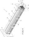
- the evaporator 1 includes a shell 10 having a generally cylindrical shape with a longitudinal center axis C ( FIG. 6 ) extending generally in the horizontal direction.
- the shell 10 includes a connection head member 13 defining an inlet water chamber 13a and an outlet water chamber 13b, and a return head member 14 defining a water chamber 14a.
- the connection head member 13 and the return head member 14 are fixedly coupled to longitudinal ends of a cylindrical body of the shell 10.
- the inlet water chamber 13a and the outlet water chamber 13b are partitioned by a water baffle 13c.
- the connection head member 13 includes a water inlet pipe 15 through which water enters the shell 10 and a water outlet pipe 16 through which the water is discharged from the shell 10.
- the shell 10 further includes a refrigerant inlet pipe 11 and a refrigerant outlet pipe 12.
- the refrigerant inlet pipe 11 is fluidly connected to the expansion device 4 via a supply conduit 6 ( FIG. 7 ) to introduce the two-phase refrigerant into the shell 10.
- the expansion device 4 may be directly coupled at the refrigerant inlet pipe 11.
- the liquid component in the two-phase refrigerant boils and/or evaporates in the evaporator 1 and goes through phase change from liquid to vapor as it absorbs heat from the water passing through the evaporator 1.
- the vapor refrigerant is drawn from the refrigerant outlet pipe 12 to the compressor 2 by suction.
- FIG. 4 is a simplified perspective view illustrating an internal structure accommodated in the shell 10.
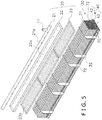
- FIG. 5 is an exploded view of the internal structure shown in FIG. 4 .
- the evaporator 1 basically includes a distributing part 20, a tube bundle 30, and a trough part 40.
- the evaporator 1 preferably further includes a baffle structure 50 as shown in FIG. 7 although illustration of the baffle structure 50 is omitted in FIGS. 4-6 for the sake of brevity.
- the distributing part 20 is configured and arranged to serve as both a gas-liquid separator and a refrigerant distributor. As shown in FIG. 5 , the distributing part 20 includes an inlet pipe part 21, a first tray part 22 and a plurality of second tray parts 23.
- the inlet pipe part 21 extends generally parallel to the longitudinal center axis C of the shell 10.
- the inlet pipe part 21 is fluidly connected to the refrigerant inlet pipe 11 of the shell 10 so that the two-phase refrigerant is introduced into the inlet pipe part 21 via the refrigerant inlet pipe 11.
- the inlet pipe part 21 includes a plurality of openings 21a disposed along the longitudinal length of the inlet pipe part 21 for discharging the two-phase refrigerant.
- the vapor component of the two-phase refrigerant flows upwardly and impinges the baffle structure 50 shown in FIG. 7 , so that liquid droplets entrained in the vapor are captured by the baffle structure 50.
- the liquid droplets captured by the baffle structure 50 are guided along a slanted surface of the baffle structure 50 toward the first tray part 22.
- the baffle structure 50 may be configured as a plate member, a mesh screen, or the like.
- the vapor component flows downwardly along the baffle structure 50 and then changes its direction upwardly toward the outlet pipe 12.
- the vapor refrigerant is discharged toward the compressor 2 via the outlet pipe 12.
- the first tray part 22 extends generally parallel to the longitudinal center axis C of the shell 10. As shown in FIG. 7 , a bottom surface of the first tray part 22 is disposed below the inlet pipe part 21 to receive the liquid refrigerant discharged from the openings 21a of the inlet pipe part 21.
- the inlet pipe part 21 is disposed within the first tray part 22 so that no vertical gap is formed between the bottom surface of the first tray part 22 and the inlet pipe part 21 as shown in FIG. 7 .
- a majority of the inlet pipe part 21 overlaps the first tray part 22 when viewed along a horizontal direction perpendicular to the longitudinal center axis C of the shell 10 as shown in FIG.
- the inlet pipe part 21 and the first tray part 22 may be arranged such that a larger vertical gap is formed between the bottom surface of the first tray part 22 and the inlet pipe part 21.
- the inlet pipe part 21, the first tray part 22 and the baffle structure 50 are preferably coupled together and suspended from above in an upper portion of the shell 10 in a suitable manner.
- the first tray part 22 has a plurality of first discharge apertures 22a from which the liquid refrigerant accumulated therein is discharged downwardly.
- the liquid refrigerant discharged from the first discharge apertures 22a of the first tray part 22 is received by one of the second tray parts 23 disposed below the first tray part 22.
- the distributing part 20 of the first embodiment includes three identical second try parts 23.
- the second tray parts 23 are aligned side-by-side along the longitudinal center axis C of the shell 10. As shown in FIG. 6 , an overall longitudinal length of the three second tray parts 23 is substantially the same as a longitudinal length of the first tray part 22 as shown in FIG. 6 .
- a transverse width of the second tray part 23 is set to be larger than a transverse width of the first tray part 22 so that the second tray part 23 extends over substantially an entire width of the tube bundle 30 as shown in FIG. 7 .
- the second tray parts 23 are arranged so that the liquid refrigerant accumulated in the second tray parts 23 does not communicate between the second tray parts 23. As shown in FIGS. 5 and 7 , each of the second tray parts 23 has a plurality of second discharge apertures 23a from which the liquid refrigerant is discharged downwardly toward the tube bundle 30.
- distributing part 20 is not limited to the ones described herein. Any conventional structure for distributing the liquid refrigerant downwardly onto the tube bundle 30 may be utilized to carry out the present invention.
- a conventional distributing system utilizing spraying nozzles and/or spray tree tubes may be used as the distributing part 20.
- any conventional distributing system that is compatible with a falling film type evaporator can be used as the distributing part 20 to carry out the present invention.
- the tube bundle 30 is disposed below the distributing part 20 so that the liquid refrigerant discharged from the distributing part 20 is supplied onto the tube bundle 30.
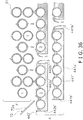
- the tube bundle 30 includes a plurality of heat transfer tubes 31 that extend generally parallel to the longitudinal center axis C of the shell 10 as shown in FIG. 6 .
- the heat transfer tubes 31 are made of materials having high thermal conductivity, such as metal.
- the heat transfer tubes 31 are preferably provided with interior and exterior grooves to further promote heat exchange between the refrigerant and the water flowing inside the heat transfer tubes 31.
- Such heat transfer tubes including the interior and exterior grooves are well known in the art.
- Thermoexel-E tubes by Hitachi Cable Ltd. may be used as the heat transfer tubes 31 of this embodiment. As shown in FIG.
- the heat transfer tubes 31 are supported by a plurality of vertically extending support plates 32, which are fixedly coupled to the shell 10.
- the tube bundle 30 is arranged to form a two-pass system, in which the heat transfer tubes 31 are divided into a supply line group disposed in a lower portion of the tube bundle 30.
- inlet ends of the heat transfer tubes 31 in the supply line group are fluidly connected to the water inlet pipe 15 via the inlet water chamber 13a of the connection head member 13 so that water entering the evaporator 1 is distributed into the heat transfer tubes 31 in the supply line group.
- Outlet ends of the heat transfer tubes 31 in the supply line group and inlet ends of the heat transfer tubes 31 of the return line tubes are fluidly communicated with a water chamber 14a of the return head member 14. Therefore, the water flowing inside the heat transfer tubes 31 in the supply line group is discharged into the water chamber 14a, and redistributed into the heat transfer tubes 31 in the return line group. Outlet ends of the heat transfer tubes 31 in the return line group are fluidly communicated with the water outlet pipe 16 via the outlet water chamber 13b of the connection head member 13. Thus, the water flowing inside the heat transfer tubes 31 in the return line group exits the evaporator 1 through the water outlet pipe 16. In a typical two-pass evaporator, the temperature of the water entering at the water inlet pipe 15 may be about 54 degrees F.
- the evaporator 1 is arranged to form a two-pass system in which the water goes in and out on the same side of the evaporator 1, it will be apparent to those skilled in the art from this disclosure that the other conventional system such as a one-pass or three-pass system may be used.
- the return line group may be disposed below or side-by-side with the supply line group instead of the arrangement illustrated herein.
- FIG. 7 is a simplified transverse cross sectional view of the evaporator 1 taken along a section line 7-7' in FIG. 3 .
- the refrigerant in a two-phase state is supplied through the supply conduit 6 to the inlet pipe part 21 of the distributing part 20 via the inlet pipe 11.
- FIG. 7 the flow of refrigerant in the refrigeration circuit is schematically illustrated, and the inlet pipe 11 is omitted for the sake of brevity.
- the vapor component of the refrigerant supplied to the distributing part 20 is separated from the liquid component in the first tray section 22 of the distributing part 20 and exits the evaporator 1 through the outlet pipe 12.
- the liquid component of the two-phase refrigerant is accumulated in the first tray part 22 and then in the second tray parts 23, and discharged from the discharge apertures 23a of the second tray part 23 downwardly towards the tube bundle 30.
- the tube bundle 30 of the first example includes a falling film region F and an accumulating region A.
- the heat transfer tubes 31 in the falling film region F are configured and arranged to perform falling film evaporation of the liquid refrigerant. More specifically, the heat transfer tubes 31 in the falling film region F are arranged such that the liquid refrigerant discharged from the distributing part 20 forms a layer (or a film) along an exterior wall of each of the heat transfer tubes 31, where the liquid refrigerant evaporates as vapor refrigerant while it absorbs heat from the water flowing inside the heat transfer tubes 31. As shown in FIG.
- the heat transfer tubes 31 in the falling film region F are arranged in a plurality of vertical columns extending parallel to each other when seen in a direction parallel to the longitudinal center axis C of the shell 10 (as shown in FIG. 7 ). Therefore, the refrigerant falls downwardly from one heat transfer tube to another by force of gravity in each of the columns of the heat transfer tubes 31.
- the columns of the heat transfer tubes 31 are disposed with respect to the second discharge openings 23a of the second tray part 23 so that the liquid refrigerant discharged from the second discharge openings 23a is deposited onto an uppermost one of the heat transfer tubes 31 in each of the columns.
- the columns of the heat transfer tubes 31 in the falling film region F are arranged in a staggered pattern as shown in FIG. 7 .
- a vertical pitch between two adjacent ones of the heat transfer tubes 31 in the falling film region F is substantially constant.
- a horizontal pitch between two adjacent ones of the columns of the heat transfer tubes 31 in the falling film region F is substantially constant.
- the liquid refrigerant that did not evaporate in the falling film region F continues falling downwardly by force of gravity into the accumulating region A, where the trough part 40 is provided as shown in FIG. 7 .
- the trough part 40 is configured and arranged to accumulate the liquid refrigerant flowing from above so that the heat transfer tubes 31 in the accumulating region A are at least partially immersed in the liquid refrigerant that is accumulated in the trough part 40.
- a number of rows of the heat transfer tubes 31 in the accumulating region A, to which the trough part 40 is provided, is preferably about 10% to about 20% of a total number of rows of the heat transfer tubes 31 of the tube bundle 30.
- a ratio between the number of rows of the heat transfer tubes 31 in the accumulating region A and the number of the heat transfer tubes 31 in one of the columns in the falling film region F is preferably about 1:9 to about 2:8.
- a number of heat transfer tubes 31 disposed in the accumulating region A is preferably about 10% to about 20% of a total number of the heat transfer tubes in the tube bundle 30. In the example shown in FIG.
- the trough part 40 is provided to two rows of the heat transfer tubes 31 in the accumulating region A, while each of the columns of the heat transfer tubes 31 in the falling film region F includes ten rows (i.e., the total number of rows in the tube bundle 30 is twelve). It will be apparent to those skilled in the art from this disclosure that, when the evaporator has a larger capacity and includes a larger number of heat transfer tubes, the number of columns of the heat transfer tubes in the falling film region F and/or the number of rows of the heat transfer tubes in the accumulating region A also increase.
- the trough part 40 includes a first trough section 41 and a pair of second trough sections 42.
- the first trough section 41 and the second trough sections 42 extend generally parallel to the longitudinal center axis C of the shell 10 over a longitudinal length that is substantially the same as a longitudinal length of the heat transfer tubes 31.
- the first trough section 41 and the second trough sections 42 of the trough part 40 are spaced apart from an interior surface of the shell 10 when viewed along the longitudinal center axis C as seen in FIG. 7 .
- the first trough section 41 and the second trough sections 42 may be made of a variety of materials such as metal, alloy, resin, etc.
- the first trough section 41 and the second trough sections 42 are made of metallic material, such as a steel plate (steel sheet).
- the first trough section 41 and the second trough sections 42 are supported by the support plates 32.
- the support plates 32 include openings (not shown) disposed at positions corresponding to an internal region of the first trough section 41 so that all segments of the trough section 41 are in fluid communication along the longitudinal length of the first trough section 41. Therefore, the liquid refrigerant accumulated in the first trough section 41 fluidly communicates via the openings in the support plates 32 along the longitudinal length of the trough section 41.
- openings are provided in the support plates 32 at positions corresponding to an internal region of each of the second trough sections 42 so that all segments of the second trough section 42 are in fluid communication along the longitudinal length of the second trough section 42. Therefore, the liquid refrigerant accumulated in the trough section 42 fluidly communicates via the openings in the support plates 32 along the longitudinal length of the second trough section 42.
- the first trough section 41 is disposed below the lowermost row of the heat transfer tubes 31 in the accumulating region A while the second trough sections 42 are disposed below the second lowermost row of the heat transfer tubes 31.
- the second lowermost row in of the heat transfer tubes 31 in the accumulating region A is divided into two groups, and each of the second trough sections 42 is respectively disposed below each of the two groups.
- a gap is formed between the second trough sections 42 to allow an overflow of the liquid refrigerant from the second trough sections 42 toward the first trough section 41.
- the heat transfer tubes 31 in the accumulating region A are arranged so that an outermost one of the heat transfer tubes 31 in each row of the accumulating region A is disposed outwardly of an outermost column of the heat transfer tubes 31 in the falling film region F on each side of the tube bundle 30 as shown in FIG. 7 . Since the flow of liquid refrigerant tends to flare outwardly as it progresses toward the lower region of the tube bundle 30 due to vapor flow within the shell 10, it is preferable to provide at least one heat transfer tube in each row of the accumulating region A, which is disposed outwardly of the outermost column of the heat transfer tubes 31 in the falling film region F as shown in FIG. 7 .
- FIG. 8 shows an enlarged cross sectional view of the region X in FIG. 7 schematically illustrating a state in which the evaporator 1 is in use under normal conditions.
- Water flowing inside the heat transfer tubes 31 is not illustrated in FIG. 8 for the sake of brevity.
- the liquid refrigerant forms films along the exterior surfaces of the heat transfer tubes 31 in the falling film region F and part of the liquid refrigerant evaporates as the vapor refrigerant.
- an amount of the liquid refrigerant falling along the heat transfer tubes 31 decreases as it progresses toward the lower region of the tube bundle 30 while the liquid refrigerant evaporates as the vapor refrigerant.
- the trough part 40 is provided in the accumulating region A, which is disposed in the lower region of the tube bundle 30, to accumulate the liquid refrigerant flowing from above and to redistribute the accumulated refrigerant along the longitudinal direction of the shell C. Therefore, all of the heat transfer tubes 31 in the accumulating region A are at least partially immersed in the liquid refrigerant collected in the trough part 40 according to the first embodiment. Thus, formation of dry patch in the lower region of the tube bundle 30 can be prevented, and good heat transfer efficiency of the evaporator 1 can be ensured.
- the heater transfer tubes 31 marked "2" which are disposed immediately below the ones marked "1," do not receive the liquid refrigerant from above.
- the liquid refrigerant is accumulated in the second trough sections 42 as the liquid refrigerant flows along the other heat transfer tubes 31. Therefore, the heat transfer tubes 31 immediately above the second trough sections 42 are at least partially immersed in the liquid refrigerant accumulated in the second trough sections 42.
- the liquid refrigerant accumulated in the trough sections 42 rises up along exposed surfaces of the exterior walls of the heat transfer tubes 31 as indicated by the arrows shown in FIG. 8 due to capillary action. Therefore, the liquid refrigerant accumulated in the second trough sections 42 boils and/or evaporates while absorbing heat from the water passing through the heat transfer tubes 31.
- the second trough sections 42 are designed to allow the liquid refrigerant to overflow from the second trough sections 42 onto the first trough section 41.
- outer edges of the first trough section 41 are disposed outwardly of outer edges of the second trough sections 42 as shown in FIGS. 7 and 8 .
- the heat transfer tubes 31 that are disposed immediately above the first trough section 41 are at least partially immersed in the liquid refrigerant accumulated in the first trough section 41 as shown in FIG. 8 .
- the liquid refrigerant in the trough section 41 rises up along exposed surfaces of the exterior walls of the heat transfer tubes 31 that are at least partially immersed in the accumulated refrigerant due to capillary action. Therefore, the liquid refrigerant accumulated in the first trough section 41 boils and/or evaporates while absorbing heat from the water passing inside the heat transfer tubes 31. Accordingly, heat transfer effectively takes place between the liquid refrigerant and the water flowing inside the heat transfer tubes 31 in the accumulating region A.
- the evaporator 1 preferably includes a guide part 70 arranged to guide scattered refrigerant back toward the heat transfer tubes 31 above the trough part 40.
- the guide part 70 basically includes a pair of lateral side portions 72 extending upwardly and laterally outwardly from the tube bundle 30 at a vertical position at opposite lateral sides of an upper end of the trough part 40.
- the guide part 70 includes at least one lateral side portion 72 extending upwardly and laterally outwardly from the tube bundle 30 at a vertical position at an upper end of the trough part 40, as best seen in FIG. 7 .
- Each lateral side portion 72 is formed of a plurality of separate sections that are welded to vertical plates 32 as best understood from FIGS. 4-6 .
- Each lateral side portion 72 of the guide part 70 includes an inclined section 72a that is inclined between 10 degrees and 45 degrees relative to a horizontal plane P passing through the longitudinal center axis C of the shell 10. More preferably, each inclined section 72a is inclined between 30 degrees and 45 degrees relative to the horizontal plane P. In the illustrated embodiment, each inclined section 72a is inclined about 40 degrees relative to the horizontal plane P. As seen in Figure 7 , the lateral side portions 72 and the inclined sections 72a are identical to each other, except their orientations are mirror images of each other. In the illustrated embodiment, each of the lateral side portions 72 consists only of one of the inclined sections 72a. However, it will be apparent to those skilled in the art from this disclosure that each of the lateral side portions 72 can include an additional section or additional sections if needed and/or desired.
- the second trough section 42 includes a bottom wall portion 42a and a pair of side wall portions 42b extending upwardly from transverse ends of the bottom wall portion 42a.
- the side wall portions 42b have an upwardly tapered profile in the first embodiment, the shape of the second trough section 42 is not limited to this configuration.
- the side wall portions 42b of the second trough section 42 may extend parallel to each other (see, FIG. 11B to 11D ).
- the bottom wall portion 42a and the side wall portions 42b form a recess in which the liquid refrigerant is accumulated so that the heat transfer tubes 31 are at least partially immersed in the liquid refrigerant accumulated in the second trough section 42 when the evaporator 1 is operated under normal conditions. More specifically, the side wall portions 42b of the second trough part 42 partially overlap with the heat transfer tubes 31 disposed directly above the second trough part 42 when viewed along a horizontal direction perpendicular to the longitudinal center axis C of the shell 10.
- FIG. 10 shows the trough section 42 and the heat transfer tubes 31 when viewed along the horizontal direction perpendicular to the longitudinal center axis C of the shell 10.
- An overlapping distance D1 between the side wall portions 42b and the heat transfer tubes 31 disposed immediately above the second trough section 42 as viewed along the horizontal direction perpendicular to the longitudinal center axis C of the shell 10 is set such that the heat transfer tubes 31 are at least partially immersed in the liquid refrigerant accumulated in the second trough section 42.
- the overlapping distance D1 is also set so that the liquid refrigerant reliably overflows from the second trough section 42 when the evaporator 1 runs under normal conditions.
- the overlapping distance D1 is set to be equal to or greater than one-half of a height (outer diameter) D2 of the heat transfer tube 31 (D1/D2 ⁇ 0.5).
- the overlapping distance D1 is set to be equal to or greater than three-quarters of the height (outer diameter) of the heat transfer tube 31 (D1/D2 ⁇ 0.75).
- the second trough section 42 is arranged such that, when the second trough section 42 is filled with the liquid refrigerant to the brim, at least one-half (or, more preferably, at least three-quarters) of the height (outer diameter) of each of the heat transfer tubes 31 are immersed in the liquid refrigerant.
- the overlapping distance D1 may be equal to or greater than the height D2 of the heat transfer tube 31. In such a case, the heat transfer tubes 31 are completely immersed in the liquid refrigerant accumulated in the second trough section 42.
- the overlapping distance D1 is substantially equal to or smaller than the height D2 of the heat transfer tube 31.
- a distance D3 between the bottom wall portion 42a and the heat transfer tubes 31 and a distance D4 between the side wall portion 42b and the heat transfer tube 31 are not limited to any particular distance as long as a sufficient space is formed between the heat transfer tubes 31 and the second trough section 42 to allow the liquid refrigerant flow between the heat transfer tubes 31 and the second trough section 42.
- each of the distance D3 and the distance D4 may be set to about 1 mm to about 4 mm.
- the distance D3 and the distance D4 may be the same or different.
- the first trough section 41 includes the similar structure as the second trough section 42 as described above except that the height of the first trough section 41 may be the same or different from the height of the second trough section. Since the first trough section 41 is disposed below the lowermost row of the heat transfer tubes 31, it is not necessary to overflow the liquid refrigerant from the first trough section 41. Therefore, an overall height of the first trough section 41 may be set to be higher than that of the second trough section 42.
- the overlapping distance D1 between the first trough section 41 and the heat transfer tubes 31 is set to be equal to or greater than one-half (or, more preferably, three-quarters) of the height (outer diameter) D2 of the heat transfer tube 31 as explained above.
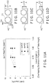
- FIG. 11A is a graph of an overall heat transfer coefficient versus the overlapping distance D1 between a trough section and the heat transfer tube 31 according to the first example.
- the vertical axis indicates the overlapping heat transfer coefficient (kw/m 2 K) and the horizontal axis indicates the overlapping distance D1 as expressed by a proportion of the height D2 of the heat transfer tube 31.
- An experiment was conducted to measure the overall heat transfer coefficient by using three samples shown in FIG. 11B to 11D . In the first sample shown in FIG.
- the overlapping distance D1 between a trough part 40' and the heat transfer tube 31 was equal to the height D2 of the heat transfer tube 31, and thus, the overlapping distance expressed by a proportion of the height of the heat transfer tube 31 was 1.0.
- the overlapping distance D1 between a trough part 40" and the heat transfer tube 31 was equal to three-quarters (0.75) of the height D2 of the heat transfer tube 31.
- the overlapping distance D1 between a trough part 40'" and the heat transfer tube 31 was equal to one-half (0.5) of the height D2 of the heat transfer tube 31.
- a distance D3 between the bottom wall of the trough section and the heat transfer tube 31 and a distance D4 between the side wall of the trough section and the heat transfer tube 31 were about 1 mm.
- the first to third samples were filled with the liquid refrigerant (R-134a) to the brim, and the overall heat transfer coefficient was measured under different heat flux levels (30 kw/m 2 , 20 kw/m 2 , and 15 kw/m 2 ).
- the overall heat transfer coefficient in the second sample with the overlapping distance of 0.75 was substantially the same as the overall heat transfer coefficient of the first sample with the overlapping distance of 1.0 ( FIG. 11B ) under all heat flux levels.
- the overall heat transfer coefficient in the third sample with the overlapping distance of 0.5 was about 80% of the overall heat transfer coefficient as the first sample ( FIG. 11B ) under the higher heat flux level (30 kw/m 2 )
- the overall heat transfer coefficient in the third sample ( FIG. 11D ) was about 90% of the overall heat transfer coefficient of the first sample ( FIG. 11B ) under the lower heat flux level (20 kw/m 2 ).
- the overlapping distance D1 is preferably set to be equal to or greater than one-half (0.5), and more preferably equal to or greater than three-quarters (0.75), of the height of the heat transfer tube 31.
- the liquid refrigerant is accumulated in the trough part 40 in the accumulating region A so that the heat transfer tubes 31 disposed in a lower region of the tube bundle 30 are at least partially immersed in the liquid refrigerant accumulated in the trough part. Therefore, even when the liquid refrigerant is not evenly distributed from above, formation of dry patches in the lower region of the tube bundle 30 can be readily prevented.
- the trough part 40 is disposed adjacent to the heat transfer tubes 31 and spaced apart from the interior surface of the shell 10, the amount of refrigerant charge can be greatly reduced as compared to a conventional hybrid evaporator including a flooded section, which forms a pool of refrigerant at a bottom portion of an evaporator shell, while ensuring good heat transfer performance.
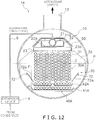
- FIG. 12 is a simplified transverse cross sectional view of an evaporator 1A illustrating a first modified example for an arrangement of a tube bundle 30A and a trough part 40A according to the first example.
- the evaporator 1A is basically the same as the evaporator 1 illustrated in FIGS. 2 to 7 except that the outermost one of the heat transfer tubes 31 in the accumulating region A in each row is vertically aligned with the outermost column of the heat transfer tubes 31 in the falling film region F on each side of the tube bundle 30A as shown in FIG. 12 .
- FIG. 13 is a simplified transverse cross sectional view of an evaporator 1B illustrating a second modified example for an arrangement of a tube bundle 30B and a trough part 40B according to the first example.
- the evaporator 1B is basically the same as the evaporator 1A shown in FIG. 12 except that the heat transfer tubes 31 of the tube bundle 30B in the falling film region F are arranged not in a staggered pattern, but in a matrix as shown in FIG. 13 .
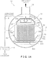
- FIG. 14 is a simplified transverse cross sectional view of an evaporator 1C illustrating a third modified example for an arrangement of a tube bundle 30C and a trough part 40C according to the first example.
- the evaporator 1C is basically the same as the evaporator 1B shown in FIG. 13 except that the trough part 40C includes a single second trough section 42C that extends continuously in the transverse direction. In such a case too, the liquid refrigerant accumulated in the second trough section 42C overflows from both transverse sides of the second trough section 42C towards a first trough section 41C.
- FIG. 15 is a simplified transverse cross sectional view of an evaporator 1D illustrating a fourth modified example for an arrangement of a tube bundle 30D and a trough part 40D according to the first example.
- the trough part 40D includes a plurality of individual trough sections 43 that are disposed respectively below the heat transfer tubes 31 in the accumulating region A.
- FIG. 16 is an enlarged schematic cross sectional view of the heat transfer tubes 31 and the trough sections 43 disposed in region Y in FIG. 15 illustrating a state in which the evaporator 1D is in use.
- the liquid refrigerant accumulated in the trough sections 43 in the uppermost row in the accumulating region A overflows towards the trough sections 43 disposed downwardly as shown in FIG. 16 . Therefore, all of the heat transfer tubes 31 in the accumulating region A are at least partially immersed in the liquid refrigerant accumulated in the trough sections 43. Accordingly, the liquid refrigerant evaporates as the vapor refrigerant as heat transfer takes place between the liquid refrigerant and the water flowing inside the heat transfer tubes 31.
- the shape of the trough section 43 is not limited to the configuration illustrated in FIGS. 15 and 16 .
- a cross section of the trough section 43 may have C-shape, V-shape, U-shape or the like.
- the overlapping distance between the trough section 43 and the heat transfer tube 31 disposed directly above the trough section 43 is preferably set to be equal to or greater than one-half (0.5), and more preferably equal to or greater than three-quarters (0.75), of the height of the heat transfer tube 31 as viewed along the horizontal direction perpendicular to the longitudinal center axis C.
- FIG. 17 is a simplified transverse cross sectional view of an evaporator 1E illustrating a fifth modified example for an arrangement of a tube bundle 30E and a trough part 40E according to the first example.
- the evaporator 1E is basically the same as the evaporator 1D illustrated in FIG. 16 except that the outermost one of the heat transfer tubes 31 in the accumulating region A in each row is vertically aligned with the outermost column of the heat transfer tubes 31 in the falling film region F on each side of the tube bundle 30E as shown in FIG. 17 .
- FIG. 18 is a simplified transverse cross sectional view of an evaporator 1F illustrating a sixth modified example for an arrangement of a tube bundle 30F and a trough part 40F according to the first example.
- the evaporator 1A is basically the same as the evaporator 1 illustrated in FIGS. 2 to 7 except for an arrangement pattern of the heat transfer tubes 31 in the falling film region F. More specifically, in the example shown in FIG. 18 , the heat transfer tubes 31 in the falling film region F are arranged so that a vertical pitch between two adjacent ones of the heat transfer tubes 31 in each column is larger in an upper region of the falling film region F than in a lower region of the falling film region F. Moreover, the heat transfer tubes 31 in the falling film region F are arranged so that a horizontal pitch between two adjacent columns of the heat transfer tubes is larger in a transverse center region of the falling film region F than in an outer region of the falling film region F.
- An amount of vapor flow in the shell 10 tends to be larger in the upper region of the falling film region F than in the lower region of the falling film region F.
- the amount of vapor flow in the shell 10 tends to be larger in the transverse center region of the falling film region F than in the outer region of the falling film region F. Therefore, the vapor velocity in the upper region and the outer region of the falling film region F often become very high.
- the transverse vapor flow causes disruption of the vertical flow of the liquid refrigerant between the heat transfer tubes 31.
- the liquid refrigerant may be carried over by the high velocity vapor flow to the compressor 2, and the entrained liquid refrigerant may damage the compressor 2. Accordingly, in the example shown in FIG.
- the vertical pitch and the horizontal pitch of the heat transfer tubes 31 are adjusted to enlarge cross sectional areas of vapor passages formed between the heat transfer tubes 31 in the upper region and the outer region of the falling film region F. Accordingly, the velocity of the vapor flow in the upper region and the outer region of the falling film region F can be decreased. Therefore, disruption of vertical flow of the liquid refrigerant and occurrence of entrained liquid refrigerant by the vapor flow can be prevented.
- an evaporator 101 in accordance with a second example will now be explained.
- the parts of the second example that are identical to the parts of the first example will be given the same reference numerals as the parts of the first example.
- the descriptions of the parts of the second example that are identical to the parts of the first example may be omitted for the sake of brevity.
- the evaporator 101 according to the second example is basically the same as the evaporator 1 of the first example except that the evaporator 101 of the second example is provided with a refrigerant recirculation system.
- a trough part 140 of the second example is basically the same as the trough part 40 of the first example.
- the refrigerant charge can be set to a prescribed amount with which almost all the liquid refrigerant evaporates in the falling film region F or the accumulating region A.
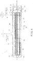
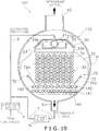
- the refrigerant recirculation system is provided to the evaporator 101 for recirculating the liquid refrigerant, which has overflowed from the trough part 140 and accumulated in a bottom portion of a shell 110.
- the shell 110 includes a bottom outlet pipe 17 in fluid communication with a conduit 7 that is coupled to a pump device 7a as shown in FIG. 19 .
- the pump device 7a is selectively operated so that the liquid refrigerant accumulated in the bottom portion of the shell 110 recirculates back to the distribution part 20 of the evaporator 110 via the conduit 6 and the inlet pipe 11 ( FIG. 1 ).
- the bottom outlet pipe 17 may be placed at any longitudinal position of the shell 110.
- the pump device 7a may be replaced by an ejector device which operates on Bernoulli's principal to draw the liquid refrigerant accumulated in the bottom portion of the shell 110 using the pressurized refrigerant from the condenser 3.
- an ejector device combines the functions of an expansion device and a pump.
- the liquid refrigerant that did not evaporate can be efficiently recirculated and reused for heat transfer, thereby reducing the amount of refrigerant charge.
- the arrangements for a tube bundle 130 and the trough part 140 are not limited to the ones illustrated in FIG. 19 . It will be apparent to those skilled in the art from this disclosure that various changes and modifications can be made herein without departing from the scope of the invention.
- the arrangements of the tube bundle and the trough part shown in FIGS. 12-15 , 17 and 18 can also be used in the evaporator 110 according to the second example.
- an evaporator 201 in accordance with a third example will now be explained.
- the parts of the third example that are identical to the parts of the first or second example will be given the same reference numerals as the parts of the first or second example.
- the descriptions of the parts of the third example that are identical to the parts of the first or second example may be omitted for the sake of brevity.
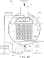
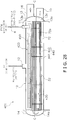
- the evaporator 201 of the third example is similar to the evaporator 101 of the second example in that the evaporator 201 is provided with the refrigerant recirculation system, which recirculates the liquid refrigerant accumulated at the bottom portion of a shell 210 via the bottom outlet pipe 17 and the conduit 7.
- the compressor 2 ( FIG. 1 ) of the vapor compression system utilizes lubrication oil, the oil tends to migrate from the compressor 2 into the refrigeration circuit of the vapor compression system.
- the refrigerant that enters the evaporator 201 contains the compressor oil (refrigerant oil).
- the evaporator 201 of the third example is configured and arranged to accumulate the oil using a trough part 240, and discharge the accumulated oil outside of the evaporator 201 toward the compressor 2.
- the evaporator 201 includes the trough part 240 that is disposed below a part of the lowermost row of the heat transfer tubes 31 in a tube bundle 230.
- the trough part 240 is fluidly connected to a valve device 8a via a bypass conduit 8.
- the valve device 8a is selectively operated when the oil accumulated in the trough part 240 reaches a prescribed level to discharge the oil from the trough part 240 to outside of the evaporator 201.
- the trough part 240 is arranged such that the liquid refrigerant accumulated in the trough part 240 does not overflow from the trough part 240.
- the accumulated liquid refrigerant in the trough part 240 boils and/or evaporates as it absorbs heat from the water flowing inside the heat transfer tubes 31 immersed in the accumulated liquid refrigerant, while the oil remains in the trough part 240.
- the overlapping distance between the trough part 240 of the third embodiment and the heat transfer tube 31 disposed directly above the trough part 240 is preferably set to be equal to or greater than one-half (0.5), and more preferably equal to or greater than three-quarters (0.75), of the height of the heat transfer tube 31 as viewed along the horizontal direction perpendicular to the longitudinal center axis C.
- a region of a tube bundle 230 where the trough part 240 is disposed constitutes the accumulating region A while the rest of the tube bundle 230 constitutes the falling film region F.
- the compressor oil that has been migrated from the compressor 2 to the refrigeration circuit can be accumulated in the trough part 240 and discharged from the evaporator 201, thereby improving heat transfer efficiency in the evaporator 201.
- the arrangements for the tube bundle 230 and the trough part 240 are not limited to the ones illustrated in FIG. 20 . It will be apparent to those skilled in the art from this disclosure that various changes and modifications can be made herein without departing from the scope of the invention. Several modified examples will be explained with reference to FIGS. 21 to 23 .
- FIG. 21 is a simplified transverse cross sectional view of an evaporator 201A illustrating a first modified example for an arrangement of a tube bundle 230A and a trough part 240A according to the third example.
- the trough part 240A may be placed at a center region below the lowermost row of the heat transfer tubes 31, instead of the side region as shown in FIG. 20 .
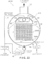
- FIG. 22 is a simplified transverse cross sectional view of an evaporator 201B illustrating a second modified example for an arrangement of a tube bundle 230B and a trough part 240B according to the third example.
- the heat transfer tubes 31 of the tube bundle 230B are arranged not in a staggered pattern, but in a matrix as shown in FIG. 22 .
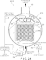
- FIG. 23 is a simplified transverse cross sectional view of an evaporator 201C illustrating a third modified example for an arrangement of a tube bundle 230C and a trough part 240C according to the third example.
- the heat transfer tubes 31 of the tube bundle 230C are arranged in a matrix.
- the trough part 240C is disposed in the center region below the lowermost row of the heat transfer tubes 31.
- the heat transfer tubes 31 of the tube bundle 230 according to the third example may be arranged in a similar manner as the heat transfer tubes 31 of the tube bundle 30F as shown in FIG. 18 .
- the heat transfer tubes 31 of the tube bundle 230 of the third example may be arranged so that a vertical pitch between the heat transfer tubes 31 is larger in an upper region of the tube bundle 230 than in a lower region of the tube bundle 230, and a horizontal pitch between the heat transfer tubes 31 is larger in an outer region of the tube bundle 230 than in a center region of the tube bundle 230.
- an evaporator 301 in accordance with a fourth example will now be explained.
- the parts of the fourth example that are identical to the parts of the first, second or third example will be given the same reference numerals as the parts of the first, second or third example.
- the descriptions of the parts of the fourth example that are identical to the parts of the first, second or third example may be omitted for the sake of brevity.
- the evaporator 301 of the fourth example is basically the same as the evaporator 1 of the first example except that an intermediate tray part 60 is provided in the falling film region F between the heat transfer tubes 31 in the supply line group and the heat transfer tubes 31 in the return line group.
- the intermediate tray part 60 includes a plurality of discharge openings 60a through which the liquid refrigerant is discharged downwardly.
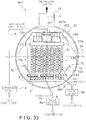
- the evaporator 301 incorporates a two pass system in which the water first flows inside the heat transfer tubes 31 in the supply line group, which is disposed in a lower region of the tube bundle 30, and then is directed to flow inside the heat transfer tubes 31 in the return line group, which is disposed in an upper region of the tube bundle 30. Therefore, the water flowing inside the heat transfer tubes 31 in the supply line group near the inlet water chamber 13a has the highest temperature, and thus, a greater amount of heat transfer is required. For example, as shown in FIG. 25 , the temperature of the water flowing inside the heat transfer tubes 31 near the inlet water chamber 13a is the highest. Therefore, a greater amount of heat transfer is required in the heat transfer tubes 31 near the inlet water chamber 13a.
- the evaporator 301 is forced to perform heat exchange by using limited surface areas of the heat transfer tubes 31 that are not dried up, and the evaporator 301 is held in equilibrium with the pressure at the time.
- more than the rated amount (e.g., twice as much) of the refrigerant charge will be required.
- the intermediate tray part 60 is disposed at a location above the heat transfer tubes 31 which requires a greater amount of heat transfer.
- the liquid refrigerant falling from above is once received by the intermediate tray part 60, and redistributed evenly toward the heat transfer tubes 31, which requires a greater amount of heat transfer. Accordingly, these portions of the heat transfer tubes 31 are readily prevented from drying up, ensuring good heat transfer performance.
- the intermediate tray part 60 is provided only partially with respect to the longitudinal direction of the tube bundle 330 as shown in FIG. 25 , the intermediate tray part 60 or a plurality of intermediate tray parts 60 may be provided to extend substantially the entire longitudinal length of the tube bundle 330.
- the arrangements for the tube bundle 330 and the trough part 40 in the fourth example are not limited to the ones illustrated in FIG. 24 . It will be apparent to those skilled in the art from this disclosure that various changes and modifications can be made herein without departing from the scope of the invention.
- the intermediate tray part 60 can be combined in any of the arrangements shown in FIGS. 12-15 and 17-23 .
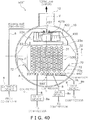
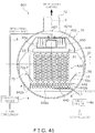
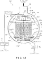
- an evaporator 401 in accordance with a first embodiment will now be explained.
- the parts of the first embodiment that are identical to the parts of previously described examples will be given the same reference numerals as the parts of the previously described examples.
- the descriptions of the parts of the first embodiment that are identical to the parts of the previously described examples may be omitted for the sake of brevity.
- the descriptions and illustrations of the previously described examples also apply to this first embodiment, except as explained and illustrated herein.
- the evaporator 401 in accordance with this first embodiment basically includes the shell 10, a modified distributing part 420, a modified tube bundle 430 (heat transferring unit), a modified trough part 440 and the guide part 70.
- the evaporator 1 preferably further includes a modified baffle structure 450 as best shown in FIG. 31 .
- the modified distributing part 420 is configured and arranged to serve as both a gas-liquid separator and a refrigerant distributor like the preceding embodiments.
- the distributing part 420 includes a modified inlet pipe part 421, a modified first tray part 422 and a plurality of second tray parts 23.
- the inlet pipe part 421 is functionally identical to the inlet pipe portion 21 and extends generally parallel to the longitudinal center axis C of the shell 10.
- the inlet pipe portion 421 in this embodiment has a rectangular cross-sectional configuration.
- the first tray part 422 is functionally identical to the first tray part 22.
- the first tray part 422 has a structure that mates with the inlet pipe part 421 to form part of the rectangular cross-sectional shape of the inlet pipe portion 421.
- the inlet pipe part 421 is fluidly connected to the refrigerant inlet pipe 11 of the shell 10 so that the two-phase refrigerant is introduced into the inlet pipe part 421 via the refrigerant inlet pipe 11.
- the inlet pipe part 421 preferably includes a first (supply) inverted U-shaped member 421a and a second (distribution) inverted U-shaped member 421b that are attached to the first tray part 422.
- the first (supply) inverted U-shaped member 421a is formed of a rigid metal sheet/plate material, which prevents liquid and gas refrigerant from passing therethrough.
- the second (distribution) inverted U-shaped member 421b is preferably formed of a rigid metal mesh (screen) material, which allows refrigerant liquid and gas to pass therethrough.
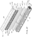
- the first and second inverted U-shaped members 421a and 421b are separate members (even though illustrated together in FIGS. 26-27 ), which are attached to the longitudinal center of the first tray part 422.
- the first tray part 422 includes a pair of longitudinally extending flanges 422a extending upwardly from a bottom surface thereof to form a central longitudinal channel 422b along a direction parallel to the center longitudinal axis C.
- the flanges 422a can be integrally formed with the firs tray part 422, can be separate flanges that are fixed to the first tray part 422 (e.g., by welding), or can be parts of a U-shaped channel that is attached to the bottom surface of the first tray part 422.
- the central longitudinal channel 422b is preferably free of openings.
- the second (distribution) inverted U-shaped member 421b is preferably formed of a rigid metal mesh
- the flanges 422a preferably extend to a predetermined height so that liquid refrigerant disposed in the channel 422b will flow over the flanges 422a upon exceeding the predetermined height.
- the second (distribution) inverted U-shaped member 421b can be formed of solid sheet/plate metal, but with holes formed therein to allow liquid and or gas refrigerant to pass therethrough.
- the holes should be disposed at the predetermined height.
- the first tray part 422 is identical to the first tray part 22. Thus, there are no holes formed within the channel 422b.
- the first and second inverted U-shaped members 421a and 421b are preferably dimensioned/sized to have free ends thereof received in the longitudinal channel to form a rectangular cross-sectional tube structure together with the flanges 422a and the bottom surface of the first tray part 422.
- the first and second inverted U-shaped members 421a and 421b are attached to the flanges or the bottom of the first tray 22 by welding, by fasteners such as nuts/bolts or any other suitable attachment technique. In the illustrated embodiment, welding is used to attach first and second inverted U-shaped members 421a and 421b to the first tray part 422.
- an additional, larger third (distribution) inverted U-shaped member 424 is attached over the second (distribution) inverted U-shaped member 421b in a spaced relationship.
- a plurality of bolts 425 extend upwardly through the second (distribution) inverted U-shaped member 421b and are attached thereto using nuts.
- the nuts act as spacers to mount the third (distribution) inverted U-shaped member 424 above the member 421b.
- the third (distribution) inverted U-shaped member 424 is laterally wider than the second (distribution) inverted U-shaped member 421b and has a height about the same or a little smaller.
- the nuts that act as spacers are relatively thin so that the free ends of the third (distribution) inverted U-shaped member 424 project downwardly below the top edges of the flanges 422a and are disposed above the bottom of the first tray 422, as best seen in FIG. 30 .
- the free ends of the bolts 425 also extend through the third (distribution) inverted U-shaped member 424, and additional nuts are used to fix the third (distribution) inverted U-shaped member 424 to the second (distribution) inverted U-shaped member 421b.
- additional nuts also act as spacers to space the baffle structure 450 upwardly from the third (distribution) inverted U-shaped member 424.
- the third (distribution) inverted U-shaped member 424 impedes the flow of refrigerant vapor therethrough.
- the liquid component of the two-phase refrigerant discharged is received by the first tray part 422.
- the vapor component of the two-phase refrigerant flows upwardly and impinges the baffle structure 450 so that liquid droplets entrained in the vapor are captured by the baffle structure 450 and flow of gaseous refrigerant from the baffle structure 450 directly to the outlet pipe 12 is reduced.
- the baffle structure 450 basically includes a canopy member 452, a first baffle member 454, a second baffle member 456 and a third baffle member 458 that are fixed together by welding or any suitable attachment technique.
- the canopy member 452 is the upper most part of the baffle.
- the third baffle member 458 is immediately under the canopy member 452.
- the second baffle member 456 is immediately below the third baffle member 458.
- the first baffle member 454 is immediately below the second baffle member 456.
- Each of the first, second and third baffle members 454, 456 and 458 are formed as inverted U-shaped members from a metal sheet/plate material.
- the legs of the first, second and third baffle members 454, 456 and 458 have cutouts formed in linearly spaced, alternating manner as best seen in FIG. 31 .
- the third baffle member 458 includes a plurality of longitudinally spaced plate-shaped tab sections 458a that are longitudinally aligned with longitudinally spaced plate-shaped tab sections 454a of the first baffle member 454.
- the second baffle member 456 includes a plurality of longitudinally spaced plate-shaped tab 456b disposed longitudinally in the gaps between the tabs 454a and 458a.
- This arrangement of the tabs 454a, 456b and 458a form a serpentine route (in the gaps) for the flow of gaseous refrigerant, to impinge the flow of gaseous refrigerant, but to allow gaseous refrigerant to flow to some degree through the baffle members 454, 456 and 458.
- the canopy member 452 includes a central portion 480 and a pair of lateral side portions 482.
- the lateral side portions 482 are identical to each other, except that they are mirror images of each other.
- the first, second and third baffle members 454, 456 and 458 are attached to the central portion 480 so that the tabs 454a, 456b and 458a project downwardly from the central portion 480 in the mounted position shown in FIG. 30 .
- the central portion 480 and the first, second and third baffle members 454, 456 and 458 have opening formed therein to receive the bolts 425.
- the nuts used to secure third (distribution) inverted U-shaped member 424 space the baffle structure 450 upwardly by contacting the first baffle member 454.
- the distributing part 420 can also be referred to as a refrigerant distribution assembly.
- the central portion 480 forms an attachment portion of the canopy member 452 attached at an upper end of the refrigerant distribution assembly.
- the central portion 480 is a planar-shaped portion.
- the lateral side portions 482 extend laterally from lateral ends of the central portion. More specifically, the lateral side portions 482 extend laterally outwardly and downwardly from a position above the refrigerant distribution assembly 420, as viewed along the longitudinal center axis C.
- Each lateral side portion 482 includes an inclined section 482a, a vertical section 482b and a flange section 482c.
- Each lateral side portion 482 has a free end formed at a bottom end of the vertical section 482b that is disposed further from a vertical plane V passing through the longitudinal center axis C than the refrigerant distribution assembly 420, as viewed along the longitudinal center axis C, and lower than an upper edge of the outermost lateral end of the refrigerant distribution assembly 420 (an upper edge of the lateral ends of the second trays 23), as viewed along the longitudinal center axis C, as seen in FIG. 30 .
- the refrigerant distribution assembly 420 has a pair of outermost lateral ends, formed at the lateral ends of the second tray parts 23.
- the upper edge of the tray parts 23 form upper edges of the laterally outermost ends of the refrigerant distribution assembly 420.
- the pair of lateral side portions 482 extend laterally outwardly and downwardly from positions above the refrigerant distribution assembly 420 so their free ends are disposed to contact the vertical plates 32 (i.e., to a vertical position corresponding to the bottom of the second trays 23).
- the free ends of the lateral side portions 482 can be spaced upwardly from the vertical plates 32.
- the flange sections 482c extend perpendicularly relative to the inclined sections 482a toward the refrigerant distribution assembly 420, and are approximately equally spaced from the central portion 480 and the vertical sections 482b.
- the liquid droplets captured by the baffle structure 450 are guided toward the first and/or second tray parts 22 and 23.
- the vapor component flows laterally through the first, second and third baffle members 454, 456 and 458, downwardly along the lateral side portions 482 and then changes its direction upwardly toward the outlet pipe 12 at the free ends of the lateral side portions 482.
- the vapor refrigerant is discharged toward the compressor 2 via the outlet pipe 12. Due to the structure of the baffle structure 450 (i.e., the canopy member 452), vapor refrigerant velocity around the free end of the lateral side portions 482 is about 0.7 m/sec as compared to about 1.0 m/s with the baffle member 50 of the preceding embodiments.
- the baffle member 450 e.g. canopy member 452 can improve performance regardless of the structure of the heat transferring unit (tube bundle 430).
- the illustrated heat transferring units (tube bundles) illustrated herein are merely preferable examples.
- the tube bundle 430 is disposed below the distributing part 420 so that the liquid refrigerant discharged from the distributing part 420 is supplied onto the tube bundle 430.
- the tube bundle 430 along with the modified trough part 440 form part of a heat transferring unit the disposed inside of the shell 10 below the refrigerant distribution assembly 420 so that the refrigerant discharged from the refrigerant distribution assembly 420 is supplied to the heat transferring unit.
- the heat transferring unit includes a plurality of heat transfer tubes 31 that extend generally parallel to the longitudinal center axis C of the shell 10.
- the tube bundle 430 is identical to the tube bundle 30, except as explained and illustrated herein.
- the modified trough part 440 requires a slightly different configuration of the lowermost heat transfer tubes 31 in the accumulating region A.
- the trough part 440 is configured and arranged to accumulate the liquid refrigerant flowing from above so that the heat transfer tubes 31 in the accumulating region A are at least partially immersed in the liquid refrigerant that is accumulated in the trough part 440.
- the trough part 440 includes modified first trough sections 441 and modified second trough sections 442.
- the first trough sections 441 and the second trough sections 442 extend generally parallel to the longitudinal center axis C of the shell 10 over a longitudinal length that is substantially the same as a longitudinal length of the heat transfer tubes 31.
- the first trough sections 441 are wider and fewer in number than the second trough sections 442.
- the first trough sections 441 are narrower and more in number than the first trough sections 41.
- the second trough sections 442 are narrower and more in number than the second trough sections 42.
- the number/width configurations of the trough sections 441 and 442 are different than the preceding embodiments (e.g., to house different numbers of the heat transfer tubes 31 as best illustrated in FIG. 29 .
- the trough sections 441 and 442 have different shaped ends than the trough sections 41 and 42.
- each of the trough sections 441 includes a bottom wall portion 441a and a pair of side wall portions 441b.
- each of the trough sections 442 includes a bottom wall portion 442a and a pair of side wall portions 442b.
- the side wall portions 441b and 442b have different heights depending on their location.
- the side wall portions 441b and 442b of the respective trough sections are mirrors images of each other, except for their heights in certain locations.
- the side wall portions 441b and 442b are identical to each other, and thus, will be given the same reference numerals for the sake of convenience.
- the heat transfer tubes 31 in the accumulating region A are arranged in at least two horizontal rows when viewed along the longitudinal center axis C of the shell 10.
- the trough part 440 includes a plurality of trough sections 441 and 442 disposed below the horizontal rows in a number of tiers (e.g., two in this embodiment) corresponding to a number of the horizontal rows of the heat transfer tubes 31 in the accumulating region A as viewed along the longitudinal center axis C.
- Two of the sidewall portions 441b in the first (lower) tier form outermost lateral ends of the first (lower) tier and a remaining number of the side wall portions 441b form inner side wall portions of the first (lower) tier.
- Any inner side wall portions 441b of the first (lower) tier have vertical heights smaller than the two of the side wall portions 441b forming the outermost lateral ends of the first (lower) tier.
- two of the sidewall portions 442b in the second (upper) tier form outermost lateral ends of the second (upper) tier and a remaining number of the side wall portions 442b form inner side wall portions of the second (upper) tier.
- Any inner side wall portions 442b of the second (upper) tier have vertical heights smaller than the two of the side wall portions 442b forming the outermost lateral ends of the second (upper) tier. This arrangement can be best understood from FIGS. 29 and 32-34 .
- two of the side wall portions 441b/442b of the trough sections 441/442 in each tier form outermost lateral ends of the tier and a remaining number of the side wall portions 441b/442b form inner side wall portions of the tier, and any inner side wall portions 441b/442b of each tier have vertical heights smaller than the two of the side wall portions 441b/442b forming the outermost lateral ends of the tier.
- the inner side wall portions 441b/442b of each tier extend vertically upward from the bottom wall portions 441a/442b to positions overlapping at least 50% of the heat transfer tubes 31 in the horizontal row above the tier. In the illustrated embodiment 50% of the heat transfer tubes 31 in the tier are overlapped by the inner side wall portions 441b/442b.
- the outer side wall portions 441b/442b vertically overlap about 100% of the heat transfer tubes in the tier.
- an outermost one of the heat transfer tubes 31 in the accumulating region A is positioned outwardly of an outermost one of the columns of the heat transfer tubes 31 in the falling film region F with respect to a transverse direction when viewed along the longitudinal center axis C of the shell 10.
- the heat transfer tubes 31 in the accumulating region A are arranged in two horizontal rows when viewed along the longitudinal center axis C of the shell 10, and the trough part 441 continuously extends laterally under the heat transfer tubes 31 disposed in the accumulating region A.
- D1 represents an overlapping distance (height) of the inner side wall portions 441b/442b
- D2 represents an overlapping distance (height) of the outermost side wall portions 441b/442b.
- D1/D2 ⁇ 0.5 as mentioned above (e.g. 0.5 in the illustrated embodiment).
- the trough part 440 is fluidly connected to a pair of valve devices 8a via a pair of bypass conduits 8 (e.g. like the third embodiment).
- the valve devices 8a are selectively operated when the oil accumulated in the trough part 440 reaches a prescribed level to discharge the oil from the trough part 440 to outside of the evaporator 401.
- the valve devices 8a and the bypass conduits 8 could be eliminated.
- a single valve device 8a could be coupled to the pair of bypass conduits 8.
- an evaporator 401' is illustrated in accordance with a modification of the first embodiment.
- the evaporator 401' is identical to the evaporator 401, except the evaporator includes a modified trough part 440'.
- the parts of this modification of the first embodiment that are identical to the parts of other embodiments or examples will be given the same reference numerals as the parts of the other embodiments or examples.
- the descriptions of the parts of this modification of the first embodiment that are identical to the parts of the other embodiments or examples may be omitted for the sake of brevity.
- the modified trough part 440' is identical to the trough part 440, except the modified trough part 440' includes modified trough sections 441' and 442'.
- the modified trough sections 441' and 442' are identical to the trough sections 441 and 442, except the dimension D1 is set to overlap 75% of the heat transfer tubes disposed in the tier at inner ends of the trough sections 441' and 442'.
- each of the trough sections 441' includes a bottom wall portion 441a' and a pair of side wall portions 441b'.
- each of the trough sections 442' includes a bottom wall portion 442a' and a pair of side wall portions 442b'.
- the side wall portions 441b' and 442b' have different heights depending on their location.
- the side wall portions 441b' and 442b' of the respective trough sections are mirrors images of each other, except for their heights in certain locations.
- the side wall portions 441b' and 442b' are identical to each other, and thus, will be given the same reference numerals for the sake of convenience.
- this second embodiment is identical to the first embodiment, except this second embodiment includes a modified trough part 540. Therefore, the descriptions and illustrations of the first embodiment also apply to this second embodiment, except as discussed and illustrated herein.
- the parts of the second embodiment that are identical to the parts of other embodiments or examples will be given the same reference numerals as the parts of the other embodiments or examples.
- the descriptions of the parts of the second embodiment that are identical to the parts of the other embodiments or examples may be omitted for the sake of brevity.
- the evaporator 501 in accordance with this second embodiment is identical to the evaporator 401 of the first embodiment, except the evaporator 501 includes a modified trough part 540.
- the modified trough part 540 includes the trough sections 442, but the trough sections 441 from the first embodiment are omitted.
- the heat transfer tubes 31 in the trough sections 441 are also eliminated to form a modified tube bundle 530. Otherwise, the tube bundle 530 (heat transferring unit) is identical to the tube bundle 430.
- the trough part 540 is fluidly connected to three valve devices 8a via three bypass conduits 8.
- the valve devices 8a are selectively operated when the oil accumulated in the trough part 540 reaches a prescribed level to discharge the oil from the trough part 540 to outside of the evaporator 501.
- the valve devices 8a and the bypass conduits 8 could be eliminated.
- a single valve device 8a could be coupled to the three bypass conduits 8.
- this second embodiment is identical to the first embodiment. Therefore, in this second embodiment, the heat transfer tubes 31 in the accumulating region A are arranged in a (single) horizontal row when viewed along the longitudinal center axis C of the shell 10, and the trough part 540 includes a plurality of laterally arranged trough sections 442 disposed below the horizontal row of the heat transfer tubes 31 in the accumulating region A as viewed along the longitudinal center axis C.
- each trough section 442 includes a bottom wall portion 442a and a pair of side wall portions 442b, with two of the side wall portions 442b forming the outermost lateral ends of the trough part 540 and a remaining number of the side wall portions 442b forming inner side wall portions.
- the inner side wall portions 442b have vertical heights smaller than the two of the side wall portions 442b forming the outermost lateral ends of the trough part 540.
- the inner side wall portions 442b extend vertically upward from the bottom wall portions to positions overlapping at least 50% of the heat transfer tubes 31 in the horizontal row.
- an outermost one of the heat transfer tubes 31 in the accumulating region A is positioned outwardly of an outermost one of the columns of the heat transfer tubes 31 in the falling film region F with respect to a transverse direction when viewed along the longitudinal center axis C of the shell 10.
- an evaporator 501' is illustrated in accordance with a modification of the second embodiment.
- the evaporator 501' is identical to the evaporator 501, except the evaporator includes a modified trough part 540'.
- the parts of this modification of the second embodiment that are identical to the parts of other embodiments or examples will be given the same reference numerals as the parts of the other embodiments or examples.
- the descriptions of the parts of this modification of the second embodiment that are identical to the parts of the other embodiments or examples may be omitted for the sake of brevity.
- the modified trough part 540' is identical to the trough part 540, except the modified trough part 540' includes modified trough sections 442' identical to the modified trough sections 442' of the modification of the first embodiment.
- the modified trough sections 442' are identical to the trough sections 442, except the dimension D1 is set to overlap 75% of the heat transfer tubes disposed in the tier.
- This third embodiment is identical to the first embodiment, except this third embodiment includes a modified trough part 640. Therefore, the descriptions and illustrations of the first embodiment also apply to this third embodiment, except as discussed and illustrated herein.
- the parts of the third embodiment that are identical to the parts of other embodiments or examples will be given the same reference numerals as the parts of the other embodiments or examples.
- the descriptions of the parts of the third embodiment that are identical to the parts of the other embodiments or examples may be omitted for the sake of brevity.
- the evaporator 601 in accordance with this third embodiment is identical to the evaporator 401 of the first embodiment, except the evaporator 601 includes a modified trough part 640.
- the modified trough part 640 includes a single trough section 642 in place of the rough sections 441 and 442 of the first embodiment. Due to the configuration of the trough section 642, a modified tube bundle 630 is formed. Otherwise, the tube bundle 630 (heat transferring unit) is identical to the tube bundle 430.
- the trough section 642 is deeper than the trough sections 441 and 442 (about twice as deep) so that two tiers of the refrigerant tubes 31 can be disposed therein.
- the trough part 642 includes a bottom wall 642a and a pair of side walls 642b.
- the side walls 642b preferably overlap 100% of the two tiers of heat transfer tubes 31 disposed therein.
- the trough section 642 is fluidly connected to a valve device 8a via a bypass conduits 8.
- the valve device 8a is selectively operated when the oil accumulated in the trough part 640 reaches a prescribed level to discharge the oil from the trough part 640 to outside of the evaporator 601.
- this third embodiment is identical to the first embodiment.
- an evaporator 701 in accordance with an fourth embodiment will now be explained.
- This fourth embodiment is identical to the first embodiment, except this fourth embodiment includes a modified trough part 740. Therefore, the descriptions and illustrations of the first embodiment also apply to this fourth embodiment, except as discussed and illustrated herein.
- the parts of the fourth embodiment that are identical to the parts of other embodiments or examples will be given the same reference numerals as the parts of the other embodiments or examples.
- the descriptions of the parts of the fourth embodiment that are identical to the parts of the other embodiments or examples may be omitted for the sake of brevity.
- the evaporator 701 in accordance with this fourth embodiment is identical to the evaporator 401 of the first embodiment, except the evaporator 701 includes a modified trough part 740.
- the modified trough part 740 includes the trough sections 442 and the trough sections 441 (of the first embodiment), but also includes an additional single trough section 744 disposed below the trough sections 441.
- the trough section 744 includes a bottom wall 744a and a pair of side walls 744b.
- the side walls 744b have heights corresponding to the inner side walls 441b and 442b.
- the side walls 744b have heights to overlap at least 50% of the heat transfer tubes 31 disposed in the trough section 744.
- the heights overlap 50% of the heat transfer tubes disposed in the additional trough section 744.
- Additional heat transfer tubes 31 are provided in the trough section 744 to form a modified tube bundle 730.
- the tube bundle 730 heat transferring unit is identical to the tube bundle 430.
- valve devices 8a and bypass conduits 8 of the first embodiment are replaced with a single valve device 8a and single bypass conduit connected to the additional trough section 744.
- the valve device 8a is selectively operated when the oil accumulated in the trough part 740 (trough section 744) reaches a prescribed level to discharge the oil from the trough part 740 to outside of the evaporator 701.
- this fourth embodiment is identical to the first embodiment.
- an evaporator 701' is illustrated in accordance with a modification of the fourth embodiment.
- the evaporator 701' is identical to the evaporator 701, except the evaporator includes a modified trough part 740'.
- the parts of this modification of the fourth embodiment that are identical to the parts of other embodiments and examples will be given the same reference numerals as the parts of the other embodiments and examples.
- the descriptions of the parts of this modification of the fourth embodiment that are identical to the parts of the other embodiments or examples may be omitted for the sake of brevity.
- the modified trough part 740' is identical to the trough part 740, except the modified trough part 740' includes modified trough sections 442', 441' (from the modification of the fifth embodiment) and a modified additional trough section 744'.
- the modified trough section 744' is set to overlap 75% of the heat transfer tubes 31 disposed in the tier, but is otherwise identical to the additional trough section 744 of the fourth embodiment.
- the following directional terms “upper”, “lower”, “above”, “downward”, “vertical”, “horizontal”, “below” and “transverse” as well as any other similar directional terms refer to those directions of an evaporator when a longitudinal center axis thereof is oriented substantially horizontally as shown in FIGS. 6 and 7 . Accordingly, these terms, as utilized to describe the present invention should be interpreted relative to an evaporator as used in the normal operating position. Finally, terms of degree such as “substantially”, “about” and “approximately” as used herein mean a reasonable amount of deviation of the modified term such that the end result is not significantly changed.
Landscapes
- Engineering & Computer Science (AREA)
- Physics & Mathematics (AREA)
- Thermal Sciences (AREA)
- Mechanical Engineering (AREA)
- General Engineering & Computer Science (AREA)
- Geometry (AREA)
- Heat-Exchange Devices With Radiators And Conduit Assemblies (AREA)
- Details Of Heat-Exchange And Heat-Transfer (AREA)
Claims (4)
- Wärmetauscher (401, 501, 401', 501', 601, 701, 701'), der dazu ausgebildet ist, in einem Dampfkompressionssystem verwendet zu werden, wobei der Wärmetauscher umfasst:eine Hülle (10) mit einer Längsmittelachse (C), die sich allgemein parallel zu einer horizontalen Ebene erstreckt;eine Kältemittelverteilungsbaugruppe (420), die innerhalb der Hülle angeordnet ist, wobei sich die Kältemittelverteilungsbaugruppe allgemein parallel zur Längsmittelachse der Hülle erstreckt, um ein Kältemittel, das in die Hülle eindringt, aufzunehmen und das Kältemittel auszulassen, wobei die Kältemittelverteilungsbaugruppe (420) ein Paar äußerster lateraler Enden aufweist;eine Wärmeübertragungseinheit (430), die innerhalb der Hülle unter der Kältemittelverteilungsbaugruppe so angeordnet ist, dass das aus der Kältemittelverteilungsbaugruppe ausgelassene Kältemittel der Wärmeübertragungseinheit zugeführt wird, wobei die Wärmeübertragungseinheit eine Vielzahl von Wärmeübertragungsrohren (31) einschließt, die sich allgemein parallel zur Längsachse erstrecken; undein Überdachungselement (452), das innerhalb des Gehäuses angeordnet ist, wobei das Überdachungselement ein Paar lateraler Seitenabschnitte (482) einschließt, die sich entlang der Längsmittelachse gesehen lateral von Positionen über der Kältemittelverteilungsbaugruppe nach außen und nach unten erstrecken,wobei jeder laterale Seitenabschnitt ein freies Ende aufweist, dasentlang der Längsmittelachse gesehen weiter von einer durch die Längsmittelachse verlaufenden vertikalen Ebene als die Kältemittelverteilungsbaugruppe, undentlang der Längsmittelachse gesehen niedriger als eine obere Kante eines der äußersten lateralen Enden der Kältemittelverteilungsbaugruppe angeordnet ist;wobeidas Überdachungselement einen mittleren Abschnitt (480) einschließt, der an einem oberen Ende der Kältemittelverteilungsbaugruppe befestigt ist, wobei sich das Paar lateraler Seitenabschnitte lateral von gegenüberliegenden lateralen Enden des mittleren Abschnitts erstrecken;wobei jeder laterale Seitenabschnitt (482) eine geneigte Sektion (482a) einschließt, die bezogen auf die vertikale Ebene geneigt ist;und dadurch gekennzeichnet, dassjeder laterale Seitenabschnitt weiter eine Flanschsektion (482c) einschließt, die sich von der geneigten Sektion (482a) zur Kältemittelverteilungsbaugruppe (420) hin erstreckt; und wobeidie Kältemittelverteilungsbaugruppe (420) einschließt:einen ersten Schalenteil (422), der innerhalb der Hülle angeordnet ist und sich allgemein parallel zur Längsmittelachse der Hülle erstreckt, um ein Kältemittel, das in die Hülle eindringt, aufzunehmen, wobei der erste Schalenteil eine Vielzahl von ersten Auslasslöchern aufweist;einen zweiten Schalenteil (23), der innerhalb der Hülle unter der ersten Schale angeordnet ist, um das aus den ersten Auslasslöchern ausgelassene Kältemittel aufzunehmen, wobei der zweite Schalenteil eine Vielzahl zweiter Auslasslöcher aufweist, undwobei die freien Enden der lateralen Seitenabschnitte niedriger angeordnet sind als ein oberes Ende des zweiten Schalenteils, und der zweite Schalenteil die äußersten lateralen Enden der Kältemittelverteilungsbaugruppe bildet.
- Wärmetauscher nach Anspruch 1, wobei
die äußersten lateralen Enden der Kältemittelverteilungsbaugruppe entlang der Längsmittelachse gesehen lateral weiter von der vertikalen Ebene angeordnet sind als die Wärmeübertragungsrohre. - Wärmetauscher nach Anspruch 1 oder 2, wobei
jeder der lateralen Seitenabschnitte weiter eine vertikale Sektion einschließt, die sich von der geneigten Sektion desselben nach unten erstreckt, um eines der freien Enden an einem unteren Ende der vertikalen Sektion zu bilden. - Wärmetauscher nach einem der Ansprüche 1-3, wobei
das Überdachungselement einen Befestigungsabschnitt einschließt, der an einem oberen Ende der Kältemittelverteilungsbaugruppe befestigt ist, wobei sich die lateralen Seitenabschnitte lateral von lateralen Enden des Befestigungsabschnitts erstrecken.
Applications Claiming Priority (2)
| Application Number | Priority Date | Filing Date | Title |
|---|---|---|---|
| US13/939,786 US9658003B2 (en) | 2013-07-11 | 2013-07-11 | Heat exchanger |
| PCT/US2014/046217 WO2015006601A1 (en) | 2013-07-11 | 2014-07-10 | Heat exchanger |
Publications (2)
| Publication Number | Publication Date |
|---|---|
| EP3019809A1 EP3019809A1 (de) | 2016-05-18 |
| EP3019809B1 true EP3019809B1 (de) | 2018-09-19 |
Family
ID=51230229
Family Applications (1)
| Application Number | Title | Priority Date | Filing Date |
|---|---|---|---|
| EP14744727.0A Active EP3019809B1 (de) | 2013-07-11 | 2014-07-10 | Wärmetauscher |
Country Status (6)
| Country | Link |
|---|---|
| US (1) | US9658003B2 (de) |
| EP (1) | EP3019809B1 (de) |
| JP (1) | JP6769870B2 (de) |
| CN (1) | CN105745508B (de) |
| ES (1) | ES2691804T3 (de) |
| WO (1) | WO2015006601A1 (de) |
Families Citing this family (16)
| Publication number | Priority date | Publication date | Assignee | Title |
|---|---|---|---|---|
| US8463441B2 (en) | 2002-12-09 | 2013-06-11 | Hudson Technologies, Inc. | Method and apparatus for optimizing refrigeration systems |
| WO2009089488A1 (en) * | 2008-01-11 | 2009-07-16 | Johnson Controls Technology Company | Heat exchanger |
| EP3087335B1 (de) * | 2013-12-24 | 2018-01-10 | Carrier Corporation | Verteiler für einen fallfilmverdampfer |
| US11073314B2 (en) * | 2015-05-27 | 2021-07-27 | Carrier Corporation | Mulitlevel distribution system for evaporator |
| US20170191718A1 (en) * | 2016-01-06 | 2017-07-06 | Johnson Controls Technology Company | Vapor compression system |
| EP3309474A1 (de) * | 2016-10-13 | 2018-04-18 | Gadlab Engineering Oy | Anordnung für absorptionsmittelkühlungseinheit und absorptionsmittelkühlungssystem |
| CN106679467B (zh) * | 2017-02-28 | 2019-04-05 | 郑州大学 | 具有外接管箱的管壳式换热器 |
| US10132537B1 (en) * | 2017-05-22 | 2018-11-20 | Daikin Applied Americas Inc. | Heat exchanger |
| CN109682131B (zh) | 2017-10-18 | 2022-03-08 | 开利公司 | 分配器、降膜式蒸发器及制冷系统 |
| CN110711397B (zh) * | 2019-10-22 | 2022-07-08 | 山东博精化工机械有限公司 | 一种具有再分配装置的降膜蒸发器 |
| CN112762734A (zh) * | 2019-11-06 | 2021-05-07 | 开利公司 | 热交换器和包括该热交换器的热交换系统 |
| CN112944735A (zh) * | 2019-12-10 | 2021-06-11 | 珠海格力电器股份有限公司 | 换热器组件、降膜式换热器和热泵机组 |
| KR102292397B1 (ko) | 2020-02-13 | 2021-08-20 | 엘지전자 주식회사 | 증발기 |
| KR102292395B1 (ko) * | 2020-02-13 | 2021-08-20 | 엘지전자 주식회사 | 증발기 |
| KR102292396B1 (ko) | 2020-02-13 | 2021-08-20 | 엘지전자 주식회사 | 증발기 |
| CN114763947B (zh) * | 2021-01-13 | 2023-05-16 | 约克(无锡)空调冷冻设备有限公司 | 蒸发器 |
Family Cites Families (15)
| Publication number | Priority date | Publication date | Assignee | Title |
|---|---|---|---|---|
| US2012183A (en) | 1934-03-09 | 1935-08-20 | Carrier Engineering Corp | Shell and tube evaporator |
| US3240265A (en) * | 1962-10-03 | 1966-03-15 | American Radiator & Standard | Refrigeration evaporator system of the flooded type |
| US3316727A (en) * | 1964-06-29 | 1967-05-02 | Carrier Corp | Absorption refrigeration systems |
| US3276217A (en) * | 1965-11-09 | 1966-10-04 | Carrier Corp | Maintaining the effectiveness of an additive in absorption refrigeration systems |
| DE1751489A1 (de) * | 1968-06-07 | 1971-07-08 | Aluminium U Metallwarenfabrik | Waermeaustauscher zur Verfluessigung oder Verdampfung von Kaeltemitteln |
| US4158295A (en) * | 1978-01-06 | 1979-06-19 | Carrier Corporation | Spray generators for absorption refrigeration systems |
| US5839294A (en) | 1996-11-19 | 1998-11-24 | Carrier Corporation | Chiller with hybrid falling film evaporator |
| US6167713B1 (en) * | 1999-03-12 | 2001-01-02 | American Standard Inc. | Falling film evaporator having two-phase distribution system |
| US6868695B1 (en) * | 2004-04-13 | 2005-03-22 | American Standard International Inc. | Flow distributor and baffle system for a falling film evaporator |
| EP1809966B1 (de) * | 2004-10-13 | 2011-07-27 | York International Corporation | Fallfilmverdampfer |
| US8561675B2 (en) | 2005-12-29 | 2013-10-22 | Industrial Technology Research Institute | Spray type heat-exchanging unit |
| WO2009089488A1 (en) * | 2008-01-11 | 2009-07-16 | Johnson Controls Technology Company | Heat exchanger |
| CN100595496C (zh) * | 2008-10-07 | 2010-03-24 | 上海环球制冷设备有限公司 | 滴淋降膜式蒸发器装置及使用方法 |
| US20110056664A1 (en) * | 2009-09-08 | 2011-03-10 | Johnson Controls Technology Company | Vapor compression system |
| US20130277020A1 (en) | 2012-04-23 | 2013-10-24 | Aaf-Mcquay Inc. | Heat exchanger |
-
2013
- 2013-07-11 US US13/939,786 patent/US9658003B2/en active Active
-
2014
- 2014-07-10 WO PCT/US2014/046217 patent/WO2015006601A1/en active Application Filing
- 2014-07-10 CN CN201480049834.XA patent/CN105745508B/zh active Active
- 2014-07-10 JP JP2016525787A patent/JP6769870B2/ja active Active
- 2014-07-10 EP EP14744727.0A patent/EP3019809B1/de active Active
- 2014-07-10 ES ES14744727.0T patent/ES2691804T3/es active Active
Non-Patent Citations (1)
| Title |
|---|
| None * |
Also Published As
| Publication number | Publication date |
|---|---|
| JP6769870B2 (ja) | 2020-10-14 |
| US20150013950A1 (en) | 2015-01-15 |
| CN105745508A (zh) | 2016-07-06 |
| ES2691804T3 (es) | 2018-11-28 |
| WO2015006601A1 (en) | 2015-01-15 |
| CN105745508B (zh) | 2018-05-15 |
| US9658003B2 (en) | 2017-05-23 |
| EP3019809A1 (de) | 2016-05-18 |
| JP2016525205A (ja) | 2016-08-22 |
Similar Documents
| Publication | Publication Date | Title |
|---|---|---|
| EP3019809B1 (de) | Wärmetauscher | |
| EP3019806B1 (de) | Wärmetauscher | |
| US10612859B2 (en) | Heat exchanger | |
| EP3036492B1 (de) | Wärmetauscher | |
| EP2841864B1 (de) | Wärmetauscher | |
| EP2841868B1 (de) | Wärmetauscher | |
| EP3427001B1 (de) | Wärmetauscher | |
| JP2016525205A5 (de) | ||
| US11029094B2 (en) | Heat exchanger | |
| US10845125B2 (en) | Heat exchanger |
Legal Events
| Date | Code | Title | Description |
|---|---|---|---|
| PUAI | Public reference made under article 153(3) epc to a published international application that has entered the european phase |
Free format text: ORIGINAL CODE: 0009012 |
|
| 17P | Request for examination filed |
Effective date: 20160111 |
|
| AK | Designated contracting states |
Kind code of ref document: A1 Designated state(s): AL AT BE BG CH CY CZ DE DK EE ES FI FR GB GR HR HU IE IS IT LI LT LU LV MC MK MT NL NO PL PT RO RS SE SI SK SM TR |
|
| AX | Request for extension of the european patent |
Extension state: BA ME |
|
| DAX | Request for extension of the european patent (deleted) | ||
| STAA | Information on the status of an ep patent application or granted ep patent |
Free format text: STATUS: EXAMINATION IS IN PROGRESS |
|
| 17Q | First examination report despatched |
Effective date: 20170428 |
|
| GRAP | Despatch of communication of intention to grant a patent |
Free format text: ORIGINAL CODE: EPIDOSNIGR1 |
|
| STAA | Information on the status of an ep patent application or granted ep patent |
Free format text: STATUS: GRANT OF PATENT IS INTENDED |
|
| INTG | Intention to grant announced |
Effective date: 20180524 |
|
| GRAS | Grant fee paid |
Free format text: ORIGINAL CODE: EPIDOSNIGR3 |
|
| GRAA | (expected) grant |
Free format text: ORIGINAL CODE: 0009210 |
|
| STAA | Information on the status of an ep patent application or granted ep patent |
Free format text: STATUS: THE PATENT HAS BEEN GRANTED |
|
| AK | Designated contracting states |
Kind code of ref document: B1 Designated state(s): AL AT BE BG CH CY CZ DE DK EE ES FI FR GB GR HR HU IE IS IT LI LT LU LV MC MK MT NL NO PL PT RO RS SE SI SK SM TR |
|
| REG | Reference to a national code |
Ref country code: GB Ref legal event code: FG4D |
|
| REG | Reference to a national code |
Ref country code: CH Ref legal event code: EP |
|
| REG | Reference to a national code |
Ref country code: AT Ref legal event code: REF Ref document number: 1043743 Country of ref document: AT Kind code of ref document: T Effective date: 20181015 |
|
| REG | Reference to a national code |
Ref country code: IE Ref legal event code: FG4D |
|
| REG | Reference to a national code |
Ref country code: DE Ref legal event code: R096 Ref document number: 602014032550 Country of ref document: DE |
|
| REG | Reference to a national code |
Ref country code: ES Ref legal event code: FG2A Ref document number: 2691804 Country of ref document: ES Kind code of ref document: T3 Effective date: 20181128 |
|
| REG | Reference to a national code |
Ref country code: NL Ref legal event code: MP Effective date: 20180919 |
|
| PG25 | Lapsed in a contracting state [announced via postgrant information from national office to epo] |
Ref country code: RS Free format text: LAPSE BECAUSE OF FAILURE TO SUBMIT A TRANSLATION OF THE DESCRIPTION OR TO PAY THE FEE WITHIN THE PRESCRIBED TIME-LIMIT Effective date: 20180919 Ref country code: LT Free format text: LAPSE BECAUSE OF FAILURE TO SUBMIT A TRANSLATION OF THE DESCRIPTION OR TO PAY THE FEE WITHIN THE PRESCRIBED TIME-LIMIT Effective date: 20180919 Ref country code: NO Free format text: LAPSE BECAUSE OF FAILURE TO SUBMIT A TRANSLATION OF THE DESCRIPTION OR TO PAY THE FEE WITHIN THE PRESCRIBED TIME-LIMIT Effective date: 20181219 Ref country code: FI Free format text: LAPSE BECAUSE OF FAILURE TO SUBMIT A TRANSLATION OF THE DESCRIPTION OR TO PAY THE FEE WITHIN THE PRESCRIBED TIME-LIMIT Effective date: 20180919 Ref country code: SE Free format text: LAPSE BECAUSE OF FAILURE TO SUBMIT A TRANSLATION OF THE DESCRIPTION OR TO PAY THE FEE WITHIN THE PRESCRIBED TIME-LIMIT Effective date: 20180919 Ref country code: GR Free format text: LAPSE BECAUSE OF FAILURE TO SUBMIT A TRANSLATION OF THE DESCRIPTION OR TO PAY THE FEE WITHIN THE PRESCRIBED TIME-LIMIT Effective date: 20181220 Ref country code: BG Free format text: LAPSE BECAUSE OF FAILURE TO SUBMIT A TRANSLATION OF THE DESCRIPTION OR TO PAY THE FEE WITHIN THE PRESCRIBED TIME-LIMIT Effective date: 20181219 |
|
| REG | Reference to a national code |
Ref country code: LT Ref legal event code: MG4D |
|
| PG25 | Lapsed in a contracting state [announced via postgrant information from national office to epo] |
Ref country code: LV Free format text: LAPSE BECAUSE OF FAILURE TO SUBMIT A TRANSLATION OF THE DESCRIPTION OR TO PAY THE FEE WITHIN THE PRESCRIBED TIME-LIMIT Effective date: 20180919 Ref country code: AL Free format text: LAPSE BECAUSE OF FAILURE TO SUBMIT A TRANSLATION OF THE DESCRIPTION OR TO PAY THE FEE WITHIN THE PRESCRIBED TIME-LIMIT Effective date: 20180919 Ref country code: HR Free format text: LAPSE BECAUSE OF FAILURE TO SUBMIT A TRANSLATION OF THE DESCRIPTION OR TO PAY THE FEE WITHIN THE PRESCRIBED TIME-LIMIT Effective date: 20180919 |
|
| REG | Reference to a national code |
Ref country code: AT Ref legal event code: MK05 Ref document number: 1043743 Country of ref document: AT Kind code of ref document: T Effective date: 20180919 |
|
| PG25 | Lapsed in a contracting state [announced via postgrant information from national office to epo] |
Ref country code: RO Free format text: LAPSE BECAUSE OF FAILURE TO SUBMIT A TRANSLATION OF THE DESCRIPTION OR TO PAY THE FEE WITHIN THE PRESCRIBED TIME-LIMIT Effective date: 20180919 Ref country code: NL Free format text: LAPSE BECAUSE OF FAILURE TO SUBMIT A TRANSLATION OF THE DESCRIPTION OR TO PAY THE FEE WITHIN THE PRESCRIBED TIME-LIMIT Effective date: 20180919 Ref country code: CZ Free format text: LAPSE BECAUSE OF FAILURE TO SUBMIT A TRANSLATION OF THE DESCRIPTION OR TO PAY THE FEE WITHIN THE PRESCRIBED TIME-LIMIT Effective date: 20180919 Ref country code: IS Free format text: LAPSE BECAUSE OF FAILURE TO SUBMIT A TRANSLATION OF THE DESCRIPTION OR TO PAY THE FEE WITHIN THE PRESCRIBED TIME-LIMIT Effective date: 20190119 Ref country code: PL Free format text: LAPSE BECAUSE OF FAILURE TO SUBMIT A TRANSLATION OF THE DESCRIPTION OR TO PAY THE FEE WITHIN THE PRESCRIBED TIME-LIMIT Effective date: 20180919 Ref country code: AT Free format text: LAPSE BECAUSE OF FAILURE TO SUBMIT A TRANSLATION OF THE DESCRIPTION OR TO PAY THE FEE WITHIN THE PRESCRIBED TIME-LIMIT Effective date: 20180919 Ref country code: EE Free format text: LAPSE BECAUSE OF FAILURE TO SUBMIT A TRANSLATION OF THE DESCRIPTION OR TO PAY THE FEE WITHIN THE PRESCRIBED TIME-LIMIT Effective date: 20180919 |
|
| PG25 | Lapsed in a contracting state [announced via postgrant information from national office to epo] |
Ref country code: SK Free format text: LAPSE BECAUSE OF FAILURE TO SUBMIT A TRANSLATION OF THE DESCRIPTION OR TO PAY THE FEE WITHIN THE PRESCRIBED TIME-LIMIT Effective date: 20180919 Ref country code: PT Free format text: LAPSE BECAUSE OF FAILURE TO SUBMIT A TRANSLATION OF THE DESCRIPTION OR TO PAY THE FEE WITHIN THE PRESCRIBED TIME-LIMIT Effective date: 20190119 Ref country code: SM Free format text: LAPSE BECAUSE OF FAILURE TO SUBMIT A TRANSLATION OF THE DESCRIPTION OR TO PAY THE FEE WITHIN THE PRESCRIBED TIME-LIMIT Effective date: 20180919 |
|
| REG | Reference to a national code |
Ref country code: DE Ref legal event code: R097 Ref document number: 602014032550 Country of ref document: DE |
|
| PLBE | No opposition filed within time limit |
Free format text: ORIGINAL CODE: 0009261 |
|
| STAA | Information on the status of an ep patent application or granted ep patent |
Free format text: STATUS: NO OPPOSITION FILED WITHIN TIME LIMIT |
|
| PG25 | Lapsed in a contracting state [announced via postgrant information from national office to epo] |
Ref country code: DK Free format text: LAPSE BECAUSE OF FAILURE TO SUBMIT A TRANSLATION OF THE DESCRIPTION OR TO PAY THE FEE WITHIN THE PRESCRIBED TIME-LIMIT Effective date: 20180919 |
|
| 26N | No opposition filed |
Effective date: 20190620 |
|
| PG25 | Lapsed in a contracting state [announced via postgrant information from national office to epo] |
Ref country code: SI Free format text: LAPSE BECAUSE OF FAILURE TO SUBMIT A TRANSLATION OF THE DESCRIPTION OR TO PAY THE FEE WITHIN THE PRESCRIBED TIME-LIMIT Effective date: 20180919 |
|
| PG25 | Lapsed in a contracting state [announced via postgrant information from national office to epo] |
Ref country code: MC Free format text: LAPSE BECAUSE OF FAILURE TO SUBMIT A TRANSLATION OF THE DESCRIPTION OR TO PAY THE FEE WITHIN THE PRESCRIBED TIME-LIMIT Effective date: 20180919 |
|
| REG | Reference to a national code |
Ref country code: CH Ref legal event code: PL |
|
| PG25 | Lapsed in a contracting state [announced via postgrant information from national office to epo] |
Ref country code: TR Free format text: LAPSE BECAUSE OF FAILURE TO SUBMIT A TRANSLATION OF THE DESCRIPTION OR TO PAY THE FEE WITHIN THE PRESCRIBED TIME-LIMIT Effective date: 20180919 |
|
| REG | Reference to a national code |
Ref country code: BE Ref legal event code: MM Effective date: 20190731 |
|
| PG25 | Lapsed in a contracting state [announced via postgrant information from national office to epo] |
Ref country code: BE Free format text: LAPSE BECAUSE OF NON-PAYMENT OF DUE FEES Effective date: 20190731 Ref country code: LU Free format text: LAPSE BECAUSE OF NON-PAYMENT OF DUE FEES Effective date: 20190710 Ref country code: LI Free format text: LAPSE BECAUSE OF NON-PAYMENT OF DUE FEES Effective date: 20190731 Ref country code: CH Free format text: LAPSE BECAUSE OF NON-PAYMENT OF DUE FEES Effective date: 20190731 |
|
| PG25 | Lapsed in a contracting state [announced via postgrant information from national office to epo] |
Ref country code: IE Free format text: LAPSE BECAUSE OF NON-PAYMENT OF DUE FEES Effective date: 20190710 |
|
| PG25 | Lapsed in a contracting state [announced via postgrant information from national office to epo] |
Ref country code: CY Free format text: LAPSE BECAUSE OF FAILURE TO SUBMIT A TRANSLATION OF THE DESCRIPTION OR TO PAY THE FEE WITHIN THE PRESCRIBED TIME-LIMIT Effective date: 20180919 |
|
| PG25 | Lapsed in a contracting state [announced via postgrant information from national office to epo] |
Ref country code: MT Free format text: LAPSE BECAUSE OF FAILURE TO SUBMIT A TRANSLATION OF THE DESCRIPTION OR TO PAY THE FEE WITHIN THE PRESCRIBED TIME-LIMIT Effective date: 20180919 Ref country code: HU Free format text: LAPSE BECAUSE OF FAILURE TO SUBMIT A TRANSLATION OF THE DESCRIPTION OR TO PAY THE FEE WITHIN THE PRESCRIBED TIME-LIMIT; INVALID AB INITIO Effective date: 20140710 |
|
| REG | Reference to a national code |
Ref country code: DE Ref legal event code: R081 Ref document number: 602014032550 Country of ref document: DE Owner name: DAIKIN INDUSTRIES, LTD., OSAKA-SHI, JP Free format text: FORMER OWNER: DAIKIN APPLIED AMERICAS INC., MINNEAPOLIS, MINN., US |
|
| REG | Reference to a national code |
Ref country code: GB Ref legal event code: 732E Free format text: REGISTERED BETWEEN 20220203 AND 20220209 |
|
| REG | Reference to a national code |
Ref country code: ES Ref legal event code: PC2A Owner name: DAIKIN INDUSTRIES,LTD Effective date: 20220513 |
|
| PG25 | Lapsed in a contracting state [announced via postgrant information from national office to epo] |
Ref country code: MK Free format text: LAPSE BECAUSE OF FAILURE TO SUBMIT A TRANSLATION OF THE DESCRIPTION OR TO PAY THE FEE WITHIN THE PRESCRIBED TIME-LIMIT Effective date: 20180919 |
|
| P01 | Opt-out of the competence of the unified patent court (upc) registered |
Effective date: 20230525 |
|
| PGFP | Annual fee paid to national office [announced via postgrant information from national office to epo] |
Ref country code: IT Payment date: 20230612 Year of fee payment: 10 Ref country code: FR Payment date: 20230608 Year of fee payment: 10 |
|
| PGFP | Annual fee paid to national office [announced via postgrant information from national office to epo] |
Ref country code: GB Payment date: 20230601 Year of fee payment: 10 Ref country code: ES Payment date: 20230801 Year of fee payment: 10 |
|
| PGFP | Annual fee paid to national office [announced via postgrant information from national office to epo] |
Ref country code: DE Payment date: 20230531 Year of fee payment: 10 |