EP3747983A1 - Biokompatibles verbundelement und verfahren zur herstellung eines biokompatiblen verbundelements - Google Patents
Biokompatibles verbundelement und verfahren zur herstellung eines biokompatiblen verbundelements Download PDFInfo
- Publication number
- EP3747983A1 EP3747983A1 EP20178400.6A EP20178400A EP3747983A1 EP 3747983 A1 EP3747983 A1 EP 3747983A1 EP 20178400 A EP20178400 A EP 20178400A EP 3747983 A1 EP3747983 A1 EP 3747983A1
- Authority
- EP
- European Patent Office
- Prior art keywords
- connecting part
- component
- transparent component
- composite element
- bioreactor
- Prior art date
- Legal status (The legal status is an assumption and is not a legal conclusion. Google has not performed a legal analysis and makes no representation as to the accuracy of the status listed.)
- Granted
Links
Images






Classifications
-
- C—CHEMISTRY; METALLURGY
- C12—BIOCHEMISTRY; BEER; SPIRITS; WINE; VINEGAR; MICROBIOLOGY; ENZYMOLOGY; MUTATION OR GENETIC ENGINEERING
- C12M—APPARATUS FOR ENZYMOLOGY OR MICROBIOLOGY; APPARATUS FOR CULTURING MICROORGANISMS FOR PRODUCING BIOMASS, FOR GROWING CELLS OR FOR OBTAINING FERMENTATION OR METABOLIC PRODUCTS, i.e. BIOREACTORS OR FERMENTERS
- C12M23/00—Constructional details, e.g. recesses, hinges
- C12M23/22—Transparent or translucent parts
-
- C—CHEMISTRY; METALLURGY
- C12—BIOCHEMISTRY; BEER; SPIRITS; WINE; VINEGAR; MICROBIOLOGY; ENZYMOLOGY; MUTATION OR GENETIC ENGINEERING
- C12M—APPARATUS FOR ENZYMOLOGY OR MICROBIOLOGY; APPARATUS FOR CULTURING MICROORGANISMS FOR PRODUCING BIOMASS, FOR GROWING CELLS OR FOR OBTAINING FERMENTATION OR METABOLIC PRODUCTS, i.e. BIOREACTORS OR FERMENTERS
- C12M37/00—Means for sterilizing, maintaining sterile conditions or avoiding chemical or biological contamination
- C12M37/04—Seals
-
- B—PERFORMING OPERATIONS; TRANSPORTING
- B32—LAYERED PRODUCTS
- B32B—LAYERED PRODUCTS, i.e. PRODUCTS BUILT-UP OF STRATA OF FLAT OR NON-FLAT, e.g. CELLULAR OR HONEYCOMB, FORM
- B32B1/00—Layered products having a non-planar shape
- B32B1/08—Tubular products
-
- B—PERFORMING OPERATIONS; TRANSPORTING
- B32—LAYERED PRODUCTS
- B32B—LAYERED PRODUCTS, i.e. PRODUCTS BUILT-UP OF STRATA OF FLAT OR NON-FLAT, e.g. CELLULAR OR HONEYCOMB, FORM
- B32B27/00—Layered products comprising a layer of synthetic resin
- B32B27/28—Layered products comprising a layer of synthetic resin comprising synthetic resins not wholly covered by any one of the sub-groups B32B27/30 - B32B27/42
- B32B27/288—Layered products comprising a layer of synthetic resin comprising synthetic resins not wholly covered by any one of the sub-groups B32B27/30 - B32B27/42 comprising polyketones
-
- B—PERFORMING OPERATIONS; TRANSPORTING
- B32—LAYERED PRODUCTS
- B32B—LAYERED PRODUCTS, i.e. PRODUCTS BUILT-UP OF STRATA OF FLAT OR NON-FLAT, e.g. CELLULAR OR HONEYCOMB, FORM
- B32B27/00—Layered products comprising a layer of synthetic resin
- B32B27/32—Layered products comprising a layer of synthetic resin comprising polyolefins
-
- C—CHEMISTRY; METALLURGY
- C08—ORGANIC MACROMOLECULAR COMPOUNDS; THEIR PREPARATION OR CHEMICAL WORKING-UP; COMPOSITIONS BASED THEREON
- C08J—WORKING-UP; GENERAL PROCESSES OF COMPOUNDING; AFTER-TREATMENT NOT COVERED BY SUBCLASSES C08B, C08C, C08F, C08G or C08H
- C08J7/00—Chemical treatment or coating of shaped articles made of macromolecular substances
- C08J7/08—Heat treatment
-
- C—CHEMISTRY; METALLURGY
- C12—BIOCHEMISTRY; BEER; SPIRITS; WINE; VINEGAR; MICROBIOLOGY; ENZYMOLOGY; MUTATION OR GENETIC ENGINEERING
- C12M—APPARATUS FOR ENZYMOLOGY OR MICROBIOLOGY; APPARATUS FOR CULTURING MICROORGANISMS FOR PRODUCING BIOMASS, FOR GROWING CELLS OR FOR OBTAINING FERMENTATION OR METABOLIC PRODUCTS, i.e. BIOREACTORS OR FERMENTERS
- C12M23/00—Constructional details, e.g. recesses, hinges
- C12M23/02—Form or structure of the vessel
-
- C—CHEMISTRY; METALLURGY
- C12—BIOCHEMISTRY; BEER; SPIRITS; WINE; VINEGAR; MICROBIOLOGY; ENZYMOLOGY; MUTATION OR GENETIC ENGINEERING
- C12M—APPARATUS FOR ENZYMOLOGY OR MICROBIOLOGY; APPARATUS FOR CULTURING MICROORGANISMS FOR PRODUCING BIOMASS, FOR GROWING CELLS OR FOR OBTAINING FERMENTATION OR METABOLIC PRODUCTS, i.e. BIOREACTORS OR FERMENTERS
- C12M23/00—Constructional details, e.g. recesses, hinges
- C12M23/02—Form or structure of the vessel
- C12M23/06—Tubular
-
- C—CHEMISTRY; METALLURGY
- C12—BIOCHEMISTRY; BEER; SPIRITS; WINE; VINEGAR; MICROBIOLOGY; ENZYMOLOGY; MUTATION OR GENETIC ENGINEERING
- C12M—APPARATUS FOR ENZYMOLOGY OR MICROBIOLOGY; APPARATUS FOR CULTURING MICROORGANISMS FOR PRODUCING BIOMASS, FOR GROWING CELLS OR FOR OBTAINING FERMENTATION OR METABOLIC PRODUCTS, i.e. BIOREACTORS OR FERMENTERS
- C12M23/00—Constructional details, e.g. recesses, hinges
- C12M23/20—Material Coatings
-
- C—CHEMISTRY; METALLURGY
- C12—BIOCHEMISTRY; BEER; SPIRITS; WINE; VINEGAR; MICROBIOLOGY; ENZYMOLOGY; MUTATION OR GENETIC ENGINEERING
- C12M—APPARATUS FOR ENZYMOLOGY OR MICROBIOLOGY; APPARATUS FOR CULTURING MICROORGANISMS FOR PRODUCING BIOMASS, FOR GROWING CELLS OR FOR OBTAINING FERMENTATION OR METABOLIC PRODUCTS, i.e. BIOREACTORS OR FERMENTERS
- C12M23/00—Constructional details, e.g. recesses, hinges
- C12M23/28—Constructional details, e.g. recesses, hinges disposable or single use
-
- C—CHEMISTRY; METALLURGY
- C12—BIOCHEMISTRY; BEER; SPIRITS; WINE; VINEGAR; MICROBIOLOGY; ENZYMOLOGY; MUTATION OR GENETIC ENGINEERING
- C12M—APPARATUS FOR ENZYMOLOGY OR MICROBIOLOGY; APPARATUS FOR CULTURING MICROORGANISMS FOR PRODUCING BIOMASS, FOR GROWING CELLS OR FOR OBTAINING FERMENTATION OR METABOLIC PRODUCTS, i.e. BIOREACTORS OR FERMENTERS
- C12M23/00—Constructional details, e.g. recesses, hinges
- C12M23/46—Means for fastening
-
- C—CHEMISTRY; METALLURGY
- C12—BIOCHEMISTRY; BEER; SPIRITS; WINE; VINEGAR; MICROBIOLOGY; ENZYMOLOGY; MUTATION OR GENETIC ENGINEERING
- C12M—APPARATUS FOR ENZYMOLOGY OR MICROBIOLOGY; APPARATUS FOR CULTURING MICROORGANISMS FOR PRODUCING BIOMASS, FOR GROWING CELLS OR FOR OBTAINING FERMENTATION OR METABOLIC PRODUCTS, i.e. BIOREACTORS OR FERMENTERS
- C12M23/00—Constructional details, e.g. recesses, hinges
- C12M23/48—Holding appliances; Racks; Supports
-
- C—CHEMISTRY; METALLURGY
- C12—BIOCHEMISTRY; BEER; SPIRITS; WINE; VINEGAR; MICROBIOLOGY; ENZYMOLOGY; MUTATION OR GENETIC ENGINEERING
- C12M—APPARATUS FOR ENZYMOLOGY OR MICROBIOLOGY; APPARATUS FOR CULTURING MICROORGANISMS FOR PRODUCING BIOMASS, FOR GROWING CELLS OR FOR OBTAINING FERMENTATION OR METABOLIC PRODUCTS, i.e. BIOREACTORS OR FERMENTERS
- C12M31/00—Means for providing, directing, scattering or concentrating light
- C12M31/02—Means for providing, directing, scattering or concentrating light located outside the reactor
-
- C—CHEMISTRY; METALLURGY
- C12—BIOCHEMISTRY; BEER; SPIRITS; WINE; VINEGAR; MICROBIOLOGY; ENZYMOLOGY; MUTATION OR GENETIC ENGINEERING
- C12M—APPARATUS FOR ENZYMOLOGY OR MICROBIOLOGY; APPARATUS FOR CULTURING MICROORGANISMS FOR PRODUCING BIOMASS, FOR GROWING CELLS OR FOR OBTAINING FERMENTATION OR METABOLIC PRODUCTS, i.e. BIOREACTORS OR FERMENTERS
- C12M41/00—Means for regulation, monitoring, measurement or control, e.g. flow regulation
-
- C—CHEMISTRY; METALLURGY
- C12—BIOCHEMISTRY; BEER; SPIRITS; WINE; VINEGAR; MICROBIOLOGY; ENZYMOLOGY; MUTATION OR GENETIC ENGINEERING
- C12M—APPARATUS FOR ENZYMOLOGY OR MICROBIOLOGY; APPARATUS FOR CULTURING MICROORGANISMS FOR PRODUCING BIOMASS, FOR GROWING CELLS OR FOR OBTAINING FERMENTATION OR METABOLIC PRODUCTS, i.e. BIOREACTORS OR FERMENTERS
- C12M41/00—Means for regulation, monitoring, measurement or control, e.g. flow regulation
- C12M41/46—Means for regulation, monitoring, measurement or control, e.g. flow regulation of cellular or enzymatic activity or functionality, e.g. cell viability
-
- B—PERFORMING OPERATIONS; TRANSPORTING
- B32—LAYERED PRODUCTS
- B32B—LAYERED PRODUCTS, i.e. PRODUCTS BUILT-UP OF STRATA OF FLAT OR NON-FLAT, e.g. CELLULAR OR HONEYCOMB, FORM
- B32B2307/00—Properties of the layers or laminate
- B32B2307/40—Properties of the layers or laminate having particular optical properties
- B32B2307/412—Transparent
-
- C—CHEMISTRY; METALLURGY
- C08—ORGANIC MACROMOLECULAR COMPOUNDS; THEIR PREPARATION OR CHEMICAL WORKING-UP; COMPOSITIONS BASED THEREON
- C08J—WORKING-UP; GENERAL PROCESSES OF COMPOUNDING; AFTER-TREATMENT NOT COVERED BY SUBCLASSES C08B, C08C, C08F, C08G or C08H
- C08J2323/00—Characterised by the use of homopolymers or copolymers of unsaturated aliphatic hydrocarbons having only one carbon-to-carbon double bond; Derivatives of such polymers
- C08J2323/02—Characterised by the use of homopolymers or copolymers of unsaturated aliphatic hydrocarbons having only one carbon-to-carbon double bond; Derivatives of such polymers not modified by chemical after treatment
- C08J2323/04—Homopolymers or copolymers of ethene
- C08J2323/06—Polyethene
-
- C—CHEMISTRY; METALLURGY
- C08—ORGANIC MACROMOLECULAR COMPOUNDS; THEIR PREPARATION OR CHEMICAL WORKING-UP; COMPOSITIONS BASED THEREON
- C08J—WORKING-UP; GENERAL PROCESSES OF COMPOUNDING; AFTER-TREATMENT NOT COVERED BY SUBCLASSES C08B, C08C, C08F, C08G or C08H
- C08J2371/00—Characterised by the use of polyethers obtained by reactions forming an ether link in the main chain; Derivatives of such polymers
- C08J2371/08—Polyethers derived from hydroxy compounds or from their metallic derivatives
- C08J2371/10—Polyethers derived from hydroxy compounds or from their metallic derivatives from phenols
Definitions
- the invention relates to the spectral process control in production processes in bioreactors.
- Bioreactors are used to cultivate microorganisms, animal and plant cells and thus open up a wide range of applications for biotech production processes. In general, there is a need to further optimize these processes. In the production of biopharmaceuticals in particular, improvements in product yield and thus profit increases are being pushed. Various approaches are available to increase the product yield, reduce the risk of contamination and reduce costs.
- the control of the processes and thus the yield can be optimized by performing a real-time process control of key parameters.
- Spectroscopic methods are particularly suitable for this, in which a measurement from outside the bioreactor is possible because this avoids contamination risks.
- Such connectors can e.g. be designed as a metal-glass composite and form e.g. a so-called Glass-To-Metal-Seal (GTMS).
- GTMS Glass-To-Metal-Seal
- cost savings in biotech production processes can also be achieved by replacing traditional stainless steel bioreactors with single-use bioreactors (also known as disposable reactors or single-use reactors).
- single-use bioreactors also known as disposable reactors or single-use reactors.
- the single-use materials used in particular pre-sterilized plastics, enable significant cost reductions depending on the intended use, not only in terms of purchase but also in operation, in particular by avoiding repeated cleaning and sterilization and the associated cleaning validation.
- the invention is therefore based on the object of being able to provide spectral process control and / or real-time data even in the case of single-use bioreactors.
- One aspect of the task is accordingly to provide an alternative to the use of glass-to-metal connectors, in particular for applications in which glass-to-metal seals (GTMS) are not preferred.
- GTMS glass-to-metal seals
- a biocompatible composite element is provided, in particular for use as a connection piece for bioreactors or other containers, preferably as a connection piece for disposable bioreactors.
- the composite element comprises an outer frame with or made of a polymer material, in particular for connection to a wall of a bioreactor, preferably for inseparable connection to a wall of a disposable bioreactor, and an inner component with or made of a transparent material, e.g. glass, in particular borosicate glass, quartz, Sapphire or glass ceramic.
- the inner component is sterile and accommodated in a hermetically sealed manner in the outer mount and forms a window, in particular in order to enable spectral process control from outside a bioreactor.
- the inner components are in particular inseparable, that is, they are permanently fixed in the outer frame.
- the composite element forms an at least sterile, preferably hermetic, seal between the polymer mount and the inner component.
- Glass-To-Polymer-Seal is particularly useful when the inner component is made of or comprises glass. In particular, these are seals in a material combination with polymers.
- Polymers for the outer frame are particularly polyethylene (PE), polypropylene (PP), polyamide (PA), polyethylene terephthalate (PET), ethylene vinyl alcohol (EVOH), polyether ether ketone (PEEK) , Polyaryletherketone (PAEK), polysulfone (PSU), polyphenylene sulfide (PPS).
- a seal with a minimum sealing effect is understood as sterile tight.
- the sealing effect is determined by a leak rate test with helium according to the A3 vacuum method of DIN EN 1779.
- a composite element according to the invention is subjected to a time-dependent test. It is described as sterile tight if the helium leak rate after 2 minutes has a value of less than 6 ⁇ 10 -4 mbar ⁇ l / s.
- a preferred form of sterile tightness is present when the helium leak rate over a period of 2 minutes has a value of less than 10 -8 mbar ⁇ l / s.
- a seal is referred to as hermetically sealed if it has a helium leak rate of less than 1.69 ⁇ 10 -10 mbar ⁇ l / s.
- the composite element or the glass-to-polymer seal is designed in particular for universal industrial use.
- the composite element or glass-to-polymer seal is particularly suitable for disposable / single-use bioreactors.
- the polymer outer frame enables sterile, tight welding to the outer wall of the bioreactor, for example polyethylene (PE) with polyethylene (PE).
- PE polyethylene
- PE polyethylene
- PE polyethylene
- the polymer material of the outer casing can therefore correspond to the polymer of the bioreactor.
- different materials are also possible.
- the composite element can accordingly be permanently connected to a wall of a bioreactor so that it can no longer be separated from it.
- the composite element according to the invention is biocompatible as described. Linked to this is, in particular, that during cultivation in bioreactors no undesirable germs can adhere to the composite element and / or grow on it.
- the areas of connection between glass and polymer and / or metal and polymer are particularly critical.
- the biocompatibility, i.e. In particular, the suppression of harmful microbial adhesion and / or harmful microbial growth can be achieved in that no edge angles of 90 ° or more are present in the aforementioned material transitions. This of course means the edge angle on the microscopic scale that is decisive for germs, the composite element can of course have elements and / or areas that are arranged perpendicular to the optical element.
- the invention provides that the microscopic edge angle between glass and polymer and / or metal and polymer is less than 90 °. This is e.g. achieved by the fact that during production the polymer wets the glass and / or metal with an edge angle of less than 90 ° or that e.g. arc-shaped recesses are made in the polymer material immediately after a material transition from metal to polymer or from glass to polymer (see also the figures and their description). A wetting angle or an edge angle between the materials of less than 85 ° can also advantageously be provided.
- At least one, preferably the majority, and very particularly preferably all of the edge angles between different materials are smaller than 90 °, preferably smaller than 85 °, on a scale relevant for germ growth. This avoids zones that favor the nucleus and thus detrimental to sterilizability at the transition between different materials (e.g. polymer-glass).
- the contact angle is determined in particular by the polymer-specific adhesion between the macromolecules and the other material.
- the principle of the invention therefore provides that a composite element can be made available that has an outer frame made of or with a polymer material and thus makes it efficient, especially for disposable bioreactors, but on the other hand is surprisingly able to produce a sterile to realize tight and biocompatible connection, whereby the optical functionality for the cultivation in such bioreactors is provided.
- the invention thus generally enables a higher product yield and more efficient process development through improved process control.
- the invention enables sterile and safe applications of spectral in-situ process control.
- Pre-sterilized single-use products are of particular importance here. Sterile cultivation conditions are mandatory, which is why a measurement must not pose a risk of contamination.
- the customary sterilizability requirement is in particular gamma radiation. In biotechnology and especially for the production of biopharmaceuticals, only approved materials are allowed.
- the polymer outer frame of the composite element according to the invention can be designed differently.
- the outer mount of the composite element can be designed to be ring-shaped in such a way that the outer mount completely surrounds the inner component in cross section.
- the cross-section of the inner component can be shaped as desired, in particular round or circular.
- the outer holder can also be tubular and thus have a first (e.g. proximal) and a second (e.g. distal) tube end, in particular such that the outer holder can be connected to the wall of the bioreactor with the first tube end.
- the outer socket preferably has a flange, in particular for connection to the wall of a bioreactor, e.g. a single-use bioreactor.
- a bioreactor e.g. a single-use bioreactor.
- the flange is preferably arranged between the first and the second pipe end, but can also be arranged on the first pipe end.
- the flange can preferably be permanently fixed, inseparably connected to the wall of the bioreactor, e.g. be welded.
- the flange and the outer mount are preferably designed in one piece, monolithically and in particular made from or with the same polymer material.
- the polymer flange can then be welded to the wall of a polymer container, in particular the outer wall of a disposable bioreactor, in a sterile, tight manner.
- the outer mount preferably has a thread, which is designed in particular as an external thread, the thread preferably being arranged on the first pipe end.
- the inner component of the composite element can also be designed differently.
- the inner component is made in one piece, namely in particular as a disk-shaped, transparent component, this transparent component being received in the outer frame in a sterile and / or hermetically sealed manner, preferably permanently fixed or inseparable.
- the transparent component can, for example, be a pane of glass.
- the glass of the transparent component comprises, for example, quartz glass or borosilicate glass or consists of this.
- the transparent component can e.g. can also be designed as a sapphire disk.
- the transparent component preferably has a transmission which is higher than 75%, in particular higher than 90%.
- the transparent component more preferably has a transmission in a spectral range with a wavelength of 190 to 2800 nm which is higher than 75%, preferably higher than 80%, particularly preferably higher than 90%. Even more preferably, the transparent component has a transmission in a spectral range n 190 to 2700 nm which is higher than 75%, particularly preferably higher than 90%.
- the transparent component is also, in particular, configured in one piece, monolithically. If the outer mount is tubular, the transparent component is preferably arranged on the second pipe end or extends essentially to the second pipe end, it being possible for a pipe overhang to be provided.
- the inner component of the composite element is designed in at least two parts, namely with a, in particular disc-shaped, transparent component and, in addition, an in particular ring-shaped or tubular connecting part.
- the connecting part is connected both to the transparent component and to the outer mount.
- the connection between the connecting part and the transparent component is designed to be sterile, preferably hermetically sealed, and can also be designed to be permanently fixed or inseparable.
- the connection between the connecting part and the outer frame is also sterile and tight, preferably hermetically tight and preferably permanently fixed or inseparable.
- the transparent component can again be designed in particular in one piece, monolithically.
- the connecting part is also preferably designed in one piece, monolithically.
- the transparent component is preferably arranged on the second pipe end and the connecting part preferably extends up to the first pipe end.
- the connecting part preferably completely encloses the transparent component in cross section, such that the transparent component is received in the connecting part in a sterile and / or hermetically sealed manner, preferably permanently fixed or inseparable, and the connecting part in turn is sterile and / or hermetically sealed, preferably permanently fixed or inseparable . is inseparable from the outer version.
- the transparent component is in contact exclusively with the connecting part.
- the transparent component is then only indirectly connected to the outer frame.
- the connecting part is preferably made with or made of metal, in particular a stainless steel, for example an austenitic-ferritic duplex steel.
- the connecting part first has a socket surrounding the transparent component, e.g. with or made of glass, in cross-section, in such a way that the transparent component is held in the socket in a sterile tight, preferably hermetically sealed manner, the socket is in turn accommodated in a sterile tight, preferably hermetically sealed, connection part and the connecting part is again sterile tight is preferably hermetically sealed, received in the outer version.
- the connecting part also preferably has a profile to increase the contact surface with the outer mount.
- grooves can be provided in the outer surface of the connecting part.
- a microstructure can in particular also be provided, which can be produced, for example, by laser processing.
- the surface of the connecting part can have a first group of grooves formed by a plurality of grooves running next to one another, which is crossed by a second group of grooves, so that a plurality or multiplicity of projections arise between the grooves (see also Figures 14 and 15 ).
- connection part adjoins the front side of the transparent component and / or is connected with the front side to the transparent component such that both the transparent component and the connection part are each sterile and / or hermetically sealed in the outer mount are received, this recording is preferably designed to be permanently fixed or inseparable.
- the connecting part can be made with or made of a transparent material, in particular the same material as the transparent component, for example glass, sapphire, ceramic or glass ceramic.
- a transparent material in particular the same material as the transparent component, for example glass, sapphire, ceramic or glass ceramic.
- it can Composite element, for example, as a glass / glass / polymer composite, as a sapphire / glass / polymer composite, as a sapphire / sapphire / polymer composite, as a glass / ceramic / polymer composite, as a sapphire / ceramic / polymer composite, as a ceramic / Ceramic / polymer composite, etc. be formed.
- the adjacent surfaces can be designed as coherent surfaces.
- the connecting part can also be made with or made of a non-transparent material, preferably ceramic or metal, in particular oxidizable metal, e.g. Aluminum, the connecting part particularly preferably having an oxide layer on a surface adjoining the transparent component.
- the oxide layer can have a thickness of at least 5 micrometers, preferably at least 10 micrometers.
- the connecting part can be designed in the form of its oxide on the joining surface. Since the connecting part is made with or from an oxidizable metal, the joining area can be adapted to the melting point of the transparent component so that laser welding can be considered.
- the connecting part e.g. made of aluminum (melting point 660 ° C) and an oxide layer of e.g.
- the melting point in this Al2O3 zone increases to 2050 ° C. This allows the joining area to be at the melting point of a transparent component, e.g. made of sapphire and therefore laser-weldable.
- a transparent component e.g. made of sapphire and therefore laser-weldable.
- the composite element in particular in the one-piece design, but also generally, can accommodate compressive stresses.
- the inner component can be accommodated in the outer mount while under compressive stress.
- the composite element is manufactured or can be manufactured as follows: The outer frame is made to expand with respect to the inner component (or, conversely, the inner component is made to contract), then the inner component, in particular the transparent component, is inserted into the outer frame and then the outer frame is made to contract with respect to the inner component (or, conversely, the inner component to expand).
- the outer frame can be made with or made of polyetheretherketone (PEEK).
- a composite element that accommodates compressive stresses can be produced, for example, by initially providing an outer mount and an inner component, the inner component being oversized with respect to the outer mount.
- the outer component (or the outer frame and the inner component) can then be heated, for example to a temperature of at least 100 ° C, preferably at least 150 ° C (for example 200 ° C), so that the outer frame expands (or expands more than the inner component) and the excess of the inner component disappears or preferably decreases.
- the inner component can accordingly continue to be oversized when the inner component is inserted into the outer mount. For example, an oversize of more than 0.01 mm, preferably more than 0.03 mm (e.g. 0.04 mm) can be provided.
- the inner component is already inserted into the outer frame with the generation of compressive stress.
- the compressive stress can increase further.
- the inner component is inserted into the outer frame with or without an oversize, it is advantageous if the inner component is finally received in the outer frame under a compressive stress of at least 50MPa, preferably more than 75MPa, particularly preferably more than 100MPa, if that The composite element is again under normal conditions, in particular room temperature.
- the compressive stress mentioned above is not the same at every point.
- the compressive stress generally decreases towards the outer end (critical end).
- the lowest compressive stress occurring (at the critical end) is still greater than 1 MPa, preferably greater than 5MPa, particularly preferably greater than 10MPa (for example 11 MPa).
- the outer mount is attached from the outside to the inner component, in particular to the connecting part and / or to the transparent component, e.g. by supplying liquid polymer material from the outside to the inner component and then curing it.
- the outer frame can be made with or made of polyethylene (PE).
- PE polyethylene
- the transparent component is received in the connecting part, it can optionally be provided that the transparent component is under compressive stress. This comes into consideration in particular for the case of a metallic connecting part, but also in general.
- a transparent component accommodated in the connecting part under compressive stress can in particular be achieved in that the inner component is manufactured or can be produced as follows: The connecting part is made to expand in relation to the transparent component (or vice versa), then the transparent component is inserted into the connecting part and then the connecting part is brought together again in relation to the transparent component (or vice versa).
- the transparent component is connected at the end to the connecting part, but also generally, it can be provided that the transparent component is connected to the connecting part in a stress-neutral manner. This comes into consideration in particular for the case of a connecting part which is made of or with the same material as the transparent component, but also in general.
- a tension-neutral connection can in particular be achieved in that the inner component is produced or can be produced as follows: The connection part is pressed onto the front of the transparent component and then the connection part is preferably firmly connected to the transparent component, in particular laser-welded.
- the outer frame in step b) and correspondingly in step d), can be subjected to positive or negative thermal expansion, such that a temperature-related thermal expansion difference is achieved between the outer frame and the inner component, in particular in step b) a positive thermal expansion (expansion) and in step d) a negative thermal expansion (contraction) is carried out.
- step bb) and correspondingly in step dd the connecting part (or the connecting part and the transparent component) can be subjected to positive or negative thermal expansion, such that a temperature-related thermal expansion difference is achieved between the connecting part and the transparent component, wherein in particular in step bb) a positive thermal expansion (expansion) and in step dd) a negative thermal expansion (contraction) is performed.
- All process sequences for the production of a biocompatible composite element furthermore preferably include, in particular as a final step, the sterilization, in particular autoclaving, of the composite element comprising the outer frame and the inner component accommodated therein in a sterile and / or hermetically sealed manner.
- the invention also relates to a bioreactor, in particular a disposable bioreactor, for the cultivation of microorganisms or animal or plant cells with one to one Wall of the bioreactor connected as a connecting piece, for example polymer-to-polymer welded, composite element as described above.
- the composite element is, in particular permanently, firmly attached to the wall as a connecting piece, e.g. welded on.
- the composite element or the connection piece can in particular have the features described above.
- the composite element has an outer frame with or made of a polymer material, the outer frame being connected to the wall of the bioreactor, in particular being connected to it in a sterile and / or hermetically tight manner.
- the composite element has an inner component with or made of a transparent material, e.g. Glass or glass ceramic, with the inner component being held in a sterile and / or hermetically tight manner in the outer holder, in particular permanently fixed, and forming a window into the bioreactor, in particular to enable spectral process control from outside the bioreactor.
- the outer socket is preferably tubular with a first and a second tube end and connected to the wall of the bioreactor, e.g. with the first pipe end connected to the wall of the bioreactor.
- the outer mount preferably has a flange and is connected to the wall of the bioreactor with the flange, the flange preferably being arranged between the first and the second pipe end or being arranged on the first pipe end.
- the bioreactor in particular designed as a disposable bioreactor, which is designed in particular to receive fluid media containing biological material, preferably has a plastic, in particular a sterilizable plastic, or consists of a plastic, in particular a sterilizable plastic.
- the bioreactor can preferably be autoclaved together with the composite element connected to it.
- the bioreactor with a composite element connected to a wall of the bioreactor as a connection piece preferably has the features of one of claims 1 to 11 with regard to the composite element.
- the invention also relates to a method for propagating or cultivating biological material, in particular microorganisms or cells, in a bioreactor, in particular a disposable bioreactor, e.g. as described above, with a biocompatible composite element connected to a wall of the bioreactor as a connection piece, in particular as described above and / or according to one of claims 1 to 11, with a spectral process control taking place from outside the bioreactor through the window formed, with in particular a physical , chemical or biological measured variable from outside the bioreactor is recorded through the window formed.
- a preferred method for propagating or cultivating biological material comprises introducing fluid, in particular biological material or a precursor biological material into a bioreactor, as described here, as well as detecting a physical, chemical or biological measured variable using a window formed by a connector as described above.
- the methods for propagation or cultivation disclosed here can advantageously include the production of pharmaceuticals, in particular biopharmaceuticals.
- the bioreactor is preferably sterilized or autoclaved after the connection piece has been connected, in particular inseparably. Measured values can then be recorded from outside the bioreactor.
- a spatially resolved measurement can preferably be carried out in order, for example, to detect metabolic processes in a spatially resolved manner.
- the method for propagating or cultivating biological material can include measuring the radiation intensity and / or the wavelength of the electromagnetic radiation inside the bioreactor, in particular spatially resolved, from outside the bioreactor.
- electromagnetic radiation of a defined wavelength preferably 250 nm
- broadband or selectively at one wavelength in particular at 270 nm
- fluorescently emitted portions of the light can be detected and evaluated with regard to defined metabolic processes within the photobioreactor.
- electromagnetic radiation of a defined wavelength preferably 250 nm
- electromagnetic radiation of a defined wavelength is radiated into the bioreactor from outside the bioreactor for a defined period of time and, after this radiation, broadband or selectively at one wavelength, in particular at 270 nm, a radiation intensity and / or wavelength of the electromagnetic radiation inside the bioreactor is measured from outside.
- photo- or mixotrophic microorganisms modified by mutagenesis in particular also microalgae, yeast and bacteria, can be used.
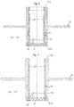
- the composite element (10) shown comprises an outer frame (20) made of a polymer, for example polyetheretherketone (PEEK), and an inner component (30) formed as a one-piece transparent component (32) made of transparent material, for example glass.
- PEEK polyetheretherketone
- This embodiment is a pressure polymerisation which e.g. can be produced as follows: The transparent component (32), in particular glass, is inserted into the polymer outer mount (20) under compressive stress.
- the outer mount (20) designed as a molded polymer part is heated (e.g. PEEK to 200 ° C), the transparent component (32) designed as a disk in this example, with a larger diameter than the inner diameter of the port, is used and cooled.
- PEEK e.g. PEEK to 200 ° C
- the transparent component (32) designed as a disk in this example with a larger diameter than the inner diameter of the port, is used and cooled.
- the polymer outer frame (20) has a flange (22), the flange (22) being arranged on the first (proximal) tube end (20p).
- a flange (22) can, however, also be provided at another point, in particular between the first pipe end (20p) and the second pipe end (20d), as shown in FIG Fig. 5 .
- the composite element (10) shown comprises an outer frame (20) made of a polymer, e.g. polyethylene (PE), and a two-part inner component (30) with a disc-shaped transparent component (32), e.g. made of glass, and a tubular connecting part (34), for example made of metal, e.g. 1.4404.
- the connecting part (34) encloses the transparent component (32).
- This embodiment is a glass / metal / polymer composite that can be produced, for example, as follows:
- the pressure glazing of the transparent component (32) takes place sterile and / or hermetically sealed in the connecting part (34), which in this example is designed as a profiled metal hollow cylinder.
- the connecting part (34) or the resulting inner component (30) is coated with a polymer, for example polyethylene (PE), polypropylene (PP), polyamide (PA), polyethylene terephthalate (PET), ethylene vinyl alcohol (EVOH), polyether ether ketone (PEEK ), Polyaryletherketone (PAEK), polysulfone (PSU), polyphenylene sulfide (PPS), or as multi-material molding with several polymers, encased in a sterile, tight manner to the component dimension, including a flange (22).
- the outer frame (20) can accordingly comprise or consist of one or more of the aforementioned materials, or be made or producible therefrom.
- the polymer outer frame (20) has a flange (22) at the first pipe end (20p).
- a flange (22) can also be provided elsewhere, in particular between the first pipe end (20p) and the second pipe end (20d), as shown in FIGS. 6 and 7 .
- the composite elements shown also have a multi-part (here: three-part) inner component (30), the connecting part (34) being both directly connected to the outer frame (20) and indirectly connected to the transparent component (32).
- the connecting part (34) is connected at the end to a mount (33) surrounding the transparent component (32) in such a way that the transparent component (32) is held in the mount (33) in a sterile, preferably hermetically sealed manner, the mount ( 33) is in turn connected to the connecting part (34) in a sterile, preferably hermetically sealed manner, and the connecting part (34) is in turn received in a sterile and sealed manner, preferably hermetically sealed, in the outer holder (20).
- the composite element (10) shown in turn comprises a polymer outer mount (20) and a two-part inner component (30) with a transparent component (32) and a tubular connecting part (34), in this example the connecting part (34) being a hollow cylinder made of transparent material, esp Glass. In this case, the connecting part (34) also adjoins the transparent component (32) at the end.
- This embodiment is a glass / glass / polymer composite which can be produced, for example, as follows:
- the connecting part (34), in particular designed as a glass cylinder, is ground and polished on the front side, and the transparent component (32 ) ground and polished, namely these components are ground and polished in such a way that coherent surfaces are created.
- the two parts are then connected in such a way that they adhere to one another via intermolecular forces (i.e. the pane is blasted against the glass cylinder).
- the two parts can then be firmly connected, for example by laser welding, in order to produce a permanently sterile-tight connection.
- the resulting inner component (30) is in turn coated with a polymer, e.g. Polyethylene (PE), encased in a sterile, tight manner to the nominal component dimension, including a flange (22).
- PE Polyethylene
- the sheathing creates the polymer outer mount (20), which in this example has a flange (22) on the first (proximal) pipe end (20p).
- a flange (22) can, however, also be formed at another point, in particular between the first pipe end (20p) and the second pipe end (20d), as shown in FIG Fig. 8 .
- Fig. 9 also shows a detailed view of the in Fig. 8 shown connecting element (10).
- the transparent component (32) protrudes from the outer frame (20) so that a protrusion U is formed. Since the wetting angle of the material of the outer mount on the material of the transparent component (20) is less than 90 °, an angle ⁇ of less than 90 ° arises between the outer mount (20) and the transparent component (32).
- the composite element (10) shown comprises a polymer outer mount (20) and a multi-part inner component (30) with a transparent component (32), a mount (33) surrounding the transparent component (32) and a tubular connecting part (34).
- the connecting part (34) is connected at the end to the mount (33) surrounding the transparent component (32) in such a way that the transparent component (32) is received in the mount (33) in a sterile, preferably hermetically sealed manner, the mount ( 33) is in turn connected to the connecting part (34) in a sterile, preferably hermetically sealed manner, and the connecting part (34) is in turn received in a sterile and sealed manner, preferably hermetically sealed, in the outer holder (20).
- the inner component (30) protrudes at least partially from the outer mount (20), in particular with the transparent component (32) and the mount (33).
- the outer frame (20) completely encloses the inner component (30) lengthways.
- the outer mount (20) again has a flange (22) at the first pipe end (20p).
- a flange (22) can, however, also be provided at another point, in particular between the first pipe end (20p) and the second pipe end (20d), as shown in FIG Fig. 10 and Fig. 12 .
- Fig. 11 and Fig. 13 also shows detailed views of the in Fig. 10 or.
- Fig. 12 shown connecting elements (10).
- An angle ⁇ of less than 90 ° is provided between the outer mount (20) and the inner component (30).
- an arcuate recess (23) is made in the outer mount (20). This recess (23) is located in the polymer material at the material transition to the inner component (30).
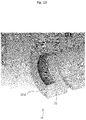
- Figures 14 and 15 show a surface of a connecting part in which a microstructure in the form of numerous projections (36) is introduced.
- FIGS 16, 17 and 18 show a bioreactor wall (40) as part of a bioreactor with a feedthrough (42) located therein, also called port (42), which forms an opening into the interior of the bioreactor, a composite element (10) at least partially in the passage (42) opening formed extends.
- the composite element (10) in this example is designed according to the in Fig. 1 shown composite element (10).
- each composite element (10) described above can extend through the passage (42) shown here.
- a measuring probe (50) is installed in the interior of the composite element (10), which makes it possible to carry out measurements inside the bioreactor, the measurement taking place through the transparent component (32) of the composite element (10).
- a sealing element (44) for example an O-ring
- the composite element (10) is preferably fluid-tight and particularly preferably sterile-tight and / or hermetically tight with respect to the feed-through (42) of the bioreactor wall (40), in particular with a positive and frictional fit .
- the measuring probe (50) in turn establishes a frictional connection to the composite element (10) by means of a friction element (46), preferably an O-ring, the friction element (46) in a cylindrical manner Recess of the composite element is held by an, in particular, essentially annular, pressure element (pressure ring) (48) which exerts a defined adjustable force on the friction element (46) in the axial direction of the composite element (10).
- a friction element preferably an O-ring
- pressure element pressure ring
- the composite element (10) is detachable, but held in a fixed position on the feed-through (42) of the bioreactor wall (40) by means of a union nut (52) designed in particular as a cap nut.
- a union nut (52) designed in particular as a cap nut.
- the union nut (52) is held on the composite element (10) in such a way that it can be rotated but cannot be lost axially with little play.
- FIGS. 20 to 24 show different views of a biocompatible composite element (10) with an outer frame (20) consisting of or comprising a polymer material, for example PE, and a multi-part inner component (30).
- an outer frame (20) consisting of or comprising a polymer material, for example PE, and a multi-part inner component (30).
- the outer mount (20) is tubular and has a flange (22) between the two tube ends (20p, 20d).
- the flange is located closer to the second pipe end (20d) than to the first pipe end (20p), although this can generally be provided for each embodiment.
- the outer mount (20) has a thread (24), although this can generally be provided for every embodiment.
- the inner component (30) which is designed in three parts in this example, comprises a tubular connecting part (34) consisting of or comprising a metal, in particular a stainless austenitic-ferritic duplex steel, eg 1.4462.
- a transparent component (32) for example with or made of sapphire, is received in the connecting part (34).
- the transparent component (32) is, in particular directly, connected to a surrounding socket (33) which is made, for example, with or from glass and which in turn is, in particular, directly connected to the connecting part (34).
- the transparent component (32) is held in the socket (33) in a sterile, preferably hermetically sealed manner
- the socket (33) is in turn connected in a sterile and sealed manner, preferably hermetically sealed, to the connecting part (34) and the connecting part (34) in turn sterile tight, preferably hermetically tight, received in the outer holder (20) in such a way that the transparent component (32) is sterile tight, preferably hermetically tight, connected to the connecting part (34) and the connecting part (34) is again sterile tight, preferably hermetically sealed tight, in the outer casing (20) is recorded.
- the holder (33) can comprise or consist of glass, for example, wherein a compact with or made of glass powder can initially be provided.
- the biocompatible composite element (10) can then be manufactured or manufactured by heating, for example in a continuous furnace, so that a glass-metal composite is created.
Landscapes
- Health & Medical Sciences (AREA)
- Chemical & Material Sciences (AREA)
- Life Sciences & Earth Sciences (AREA)
- Organic Chemistry (AREA)
- Engineering & Computer Science (AREA)
- Wood Science & Technology (AREA)
- Bioinformatics & Cheminformatics (AREA)
- Zoology (AREA)
- General Health & Medical Sciences (AREA)
- Sustainable Development (AREA)
- Microbiology (AREA)
- Biotechnology (AREA)
- Biochemistry (AREA)
- General Engineering & Computer Science (AREA)
- Biomedical Technology (AREA)
- Genetics & Genomics (AREA)
- Clinical Laboratory Science (AREA)
- Molecular Biology (AREA)
- Analytical Chemistry (AREA)
- Mechanical Engineering (AREA)
- Physics & Mathematics (AREA)
- Thermal Sciences (AREA)
- Chemical Kinetics & Catalysis (AREA)
- Medicinal Chemistry (AREA)
- Polymers & Plastics (AREA)
- Immunology (AREA)
- Cell Biology (AREA)
- Apparatus Associated With Microorganisms And Enzymes (AREA)
- Measuring Or Testing Involving Enzymes Or Micro-Organisms (AREA)
- Micro-Organisms Or Cultivation Processes Thereof (AREA)
Abstract
Description
- Die Erfindung betrifft die spektrale Prozesskontrolle bei Produktionsprozessen in Bioreaktoren.
- Bioreaktoren dienen zur Kultivierung von Mikroorganismen, tierischen und pflanzlichen Zellen und eröffnen damit ein breites Anwendungsfeld von Biotech-Produktionsprozessen. Generell besteht ein Bedarf, diese Prozesse weiter zu optimieren. Insbesondere für die Herstellung von Biopharmazeutika werden Verbesserungen der Produktausbeute und damit Gewinnsteigerungen forciert. Zur Erhöhung der Produktausbeute, der Verminderung von Kontaminationsrisiken sowie der Reduktion von Kosten stehen verschiedene Ansätze zur Verfügung.
- Einerseits kann die Steuerung der Prozesse und damit die Ausbeute dadurch optimiert werden, dass eine Echtzeit-Prozesskontrolle von Schlüsselparametern durchgeführt wird. Hierzu eignen sich insbesondere spektroskopische Verfahren bei denen eine Messung von außerhalb des Bioreaktors möglich ist, weil hierdurch Kontaminationsrisiken vermieden werden.
- Bei einem Bioreaktor mit einem Edelstahl-Kulturgefäß können solche Messungen z.B. dadurch ermöglicht werden, dass ein Flansch-Anschlussstück mit Sichtfenster montiert wird, um ein Fenster ins Innere des Bioreaktors zu schaffen. Solche Anschlussstücke können z.B. als Metall-Glas-Verbund ausgebildet sein und bilden z.B. ein sogenanntes Glass-To-Metal-Seal (GTMS).
- Andererseits können Kosteneinsparungen bei Biotech-Produktionsprozessen auch dadurch erzielt werden, dass traditionelle Edelstahl-Bioreaktoren durch Einweg-Bioreaktoren (auch als Disposable-Reaktoren oder Single-Use-Reaktoren bezeichnet) ersetzt werden. Die hierbei eingesetzten Einwegmaterialen, insbesondere vorsterilisierte Kunststoffe, ermöglichen je nach Einsatzzweck deutliche Kostenreduktionen, nicht nur bei der Anschaffung, sondern auch im Betrieb, insbesondere durch Vermeidung wiederholter Reinigung und Sterilisation und der damit verbundenen Reinigungsvalidierung.
- Auch bei Einweg-Reaktoren hängt die Ausbeute maßgeblich von der Ermittlung von Substrat- und Produktkonzentrationen ab. Gleichwohl ist für Single-Use-Anwendungen eine in-situ Prozesskontrolle nach dem Stand der Technik noch nicht hinreichend verfügbar. Der Einsatz von Glass-To-Metal-Seals (GTMS) ist bei Single-Use-Anwendungen nicht hinreichend gegeben.
- Branchenüblich werden deshalb während der Kultivierung Proben gezogen. Der Zeitaufwand ist beträchtlich. Bedingt ist dies durch den Probenzug, mit dem auch ein Kontaminationsrisiko verbunden ist, sowie durch ressourcenintensive Offline-Analytik. Trotz dieser Aufwände bleibt, insbesondere für Single-Use-Applikationen, die Prozesskontrolle durch fehlende Echtzeitdaten beeinträchtigt.
- Der Erfindung liegt demnach die Aufgabe zugrunde, eine spektrale Prozesskontrolle und/oder Echtzeitdaten auch bei Einweg-Bioreaktoren bereitstellen zu können. Ein Aspekt der Aufgabe ist es demnach, eine Alternative zum Einsatz von Glas-Metall-Anschlussstücken bereitzustellen, insbesondere für Applikationen, bei denen Glass-To-Metal-Seals (GTMS) nicht präferiert sind.
- Diese Aufgabe wird durch die Gegenstände der unabhängigen Ansprüche gelöst. Vorteilhafte Weiterbildungen der Erfindung sind in den abhängigen Ansprüchen definiert.
- Erfindungsgemäß wird ein biokompatibles Verbundelement, insbesondere zur Verwendung als Anschlussstück für Bioreaktoren oder andere Behälter, vorzugsweise als Anschlussstück für Einweg-Bioreaktoren bereitgestellt.
- Das Verbundelement umfasst eine Außenfassung mit oder aus einem Polymermaterial, insbesondere zum Anschließen an eine Wandung eines Bioreaktors, vorzugsweise zum untrennbaren Anschließen an eine Wandung eines Einweg-Bioreaktors, und eine Innenkomponente mit oder aus einem transparenten Material, z.B. Glas, insbesondere Borosikicatglas, Quarz, Saphir oder Glaskeramik. Die Innenkomponente ist steril dicht, bevorzugt hermetisch dicht in der Außenfassung aufgenommen und bildet ein Fenster, insbesondere um von außerhalb eines Bioreaktors eine spektrale Prozesskontrolle zu ermöglichen. Die Innenkomponenten ist dabei insbesondere untrennbar, also dauerhaft fest in der Außenfassung aufgenommen.
- Das Verbundelement bildet insbesondere zwischen Polymerfassung und Innenkomponente eine zumindest steril dichte, bevorzugt hermetische Dichtung. Insbesondere wenn die Innenkomponente aus Glas besteht oder Glas umfasst, bietet sich die Bezeichnung Glass-To-Polymer-Seal (GTPS) an. Es handelt sich also insbesondere um Seals in Materialkombination mit Polymeren. Als Polymere für die Außenfassung, insbesondere in Form von Homo-, Co-, oder Terpolymeren, kommen insbesondere Polyethylen (PE), Polypropylen (PP), Polyamid (PA), Polyethylenterephthalat (PET), Ethylenvinyllalkohol (EVOH), Polyeterhetherketon (PEEK), Polyaryletherketon (PAEK), Polysulfon (PSU), Polyphenylensulfid (PPS)in Betracht.
- Als steril dicht wird im Sinne der vorliegenden Erfindung eine Dichtung mit einer Mindestdichtwirkung verstanden. Die Dichtwirkung wird über eine Leckratenprüfung mit Helium nach dem Vakuumverfahren A3 der DIN EN 1779 bestimmt. Dabei wird ein erfindungsgemäßes Verbundelement einem zeitabhängigen Test unterzogen. Als steril dicht wird es bezeichnet, wenn die Heliumleckrate nach 2 Minuten einen Wert von weniger als 6·10-4 mbar·l/s aufweist. Eine bevorzugte Form der sterilen Dichtigkeit liegt vor, wenn die Heliumleckrate über einen Zeitraum von 2 Minuten einen Wert von weniger als 10-8 mbar·l/s aufweist. Vorteilhaft werden diese Leckraten jeweils auch bei einem Test über 4 Minuten erreicht.
- Bevorzugt ist eine sogar hermetische Dichtung. Als hermetisch dicht wird eine Dichtung bezeichnet, welche eine Heliumleckrate von weniger als 1,69·10-10 mbar·l/s aufweist.
- Das Verbundelement bzw. das Glass-To-Polymer-Seal ist insbesondere für eine universelle industrielle Nutzbarkeit ausgelegt. Im Speziellen eignet sich das Verbundelement bzw. Glass-To-Polymer-Seal für Disposable-/Single-Use-Bioreaktoren. Insbesondere für Single-Use-Bioreaktoren ermöglicht die Polymer-Außenfassung das steril dichte Verschweißen mit der Außenwandung des Bioreaktors, z.B. Polyethylen (PE) mit Polyethylen (PE). Das Polymermaterial der Außenfassung kann demnach dem Polymer des Bioreaktors entsprechen. Es sind aber auch verschiedene Materialien möglich. Das Verbundelement kann demnach dauerhaft fest mit einer Wandung eines Bioreaktors verbunden werden, so dass es nicht mehr davon getrennt werden kann.
- Das erfindungsgemäße Verbundelement ist wie beschrieben biokompatibel. Verbunden damit ist insbesondere, dass bei der Kultivierung in Bioreaktoren keine unerwünschten Keime an dem Verbundelement anhaften und/oder an diesem Wachsen können. Kritisch sind insbesondere die Verbindungsbereiche zwischen Glas und Polymer und/oder Metall und Polymer. Die Biokompatibilität, d.h. insbesondere die Unterdrückung der schädlichen Keimanhaftung und/oder des schädlichen Keimwachstums kann dadurch erreicht werden, dass bei den genannten Materialübergängen keine Kantenwinkel von 90° oder mehr vorhanden sind. Damit ist selbstverständlich der Kantenwinkel im für Keime maßgeblichen mikroskopischen Maßstab gemeint, das Verbundelement kann natürlich Elemente und/oder Bereiche aufweisen, die Senkrecht zum optischen Element angeordnet sind. Die Erfindung sieht vielmehr vor, dass der mikroskopische Kantenwinkel zwischen Glas und Polymer und/oder Metall und Polymer weniger als 90° beträgt. Dies wird z.B. dadurch erreicht, dass bei der Herstellung das Polymer das Glas und/oder Metall mit einem Kantenwinkel von weniger als 90° benetzt oder dass z.B. unmittelbar nach einem Materialübergang von Metall auf Polymer bzw. von Glas auf Polymer bogenförmige Ausnehmungen im Polymermaterial eingebracht sind (siehe hierzu auch die Figuren und deren Beschreibung). Vorteilhaft kann auch ein Benetzungswinkel bzw. ein Kantenwinkel zwischen den Materialien von weniger als 85° vorgesehen sein.
- Es ist demnach vorzugsweise vorgesehen, dass zumindest einer, vorzugsweise die Mehrzahl und ganz besonders bevorzugt sämtliche Kantenwinkel auf einem für Keimwachstum maßgeblichen Maßstab zwischen verschiedenen Materialien kleiner als 90°, vorzugsweise kleiner als 85° sind. Dadurch werden keimherdbegünstigende und damit der Sterilisierbarkeit abträgliche Zonen bei Übergängen verschiedener Materialien (z.B. Polymer-Glas) vermieden. Der Kontaktwinkel wird insbesondere von der polymerspezifischen Adhäsion zwischen den Makromolekülen und dem anderen Material bestimmt.
- Das Prinzip der Erfindung sieht es demzufolge vor, dass ein Verbundelement zur Verfügung gestellt werden kann, das eine Außenfassung aus oder mit einem Polymermaterial aufweist und es damit rationell insbesondere für Einweg-Bioreaktoren einsetzbar macht, andererseits aber überraschend dazu in der Lage ist, eine steril dichte und biokompatible Verbindung zu realisieren, wodurch die optische Funktionalität für die Kultivierung in solchen Bioreaktoren bereitgestellt wird.
- Die Erfindung ermöglicht damit allgemein eine höhere Produktausbeute und effizientere Prozessentwicklung durch eine verbesserte Prozesskontrolle. Insbesondere ermöglicht die Erfindung steril und sicher Anwendungen der spektralen in-situ Prozesskontrolle.
- Für die Entwicklung und Steuerung von Biotech-Produktionsprozessen sind sterile Bedingungen und Echtzeit-Messungen (Real-Time-Messungen) von Schlüsselparametern für die Entwicklung und Steuerung von Biotech-Produktionsprozessen entscheidend.
- Vorsterilisierte Single-Use-Produkte sind hierbei von besonderer Bedeutung. Sterile Kultivierungsbedingungen sind obligat, weshalb von einer Messung kein Kontaminationsrisiko ausgehen darf. Für Single-Use-Applikationen ist die branchenübliche Sterilisierbarkeitsanforderung insbesondere Gammastrahlung. In der Biotechnologie und insbesondere für die Herstellung von Biopharmazeutika sind nur zugelassene Materialen erlaubt.
- Um den strengen Anforderungen für die Herstellung von Biopharmazeutika zu genügen, können die Materialien des Verbundelements so ausgewählt sein, dass dieses jeweils den nachfolgenden Standards entsprechen:
- FDA approved materials (ICH Q7A, CFR 211.65(a) - Code of Federal Regulations, USP Class, animal derivative free, bisphenol A free)
- EMA (European Medicines Agency) EU GMP Guide Part II approved materials
- Sectoral chemical resistance - ASTM D 543-06
- Biocompatibility e.g. referred to US Pharmacopeia or tests referred to ISO 10993
- Die Polymer-Außenfassung des erfindungsgemäßen Verbundelements kann unterschiedlich ausgebildet sein.
- Insbesondere kann die Außenfassung des Verbundelements ringförmig ausgebildet, derart, dass die Außenfassung die Innenkomponente im Querschnitt vollständig umschließt. Der Querschnitt der Innenkomponente kann dabei beliebig geformt, insbesondere rund oder kreisförmig sein.
- Die Außenfassung kann außerdem rohrförmig ausgebildet sein und somit ein erstes (z.B. proximales) und ein zweites (z.B. distales) Rohrende aufweisen, insbesondere derart, dass die Außenfassung mit dem ersten Rohrende an die Wandung des Bioreaktors anschließbar ist.
- Außerdem weist die Außenfassung vorzugsweise einen Flansch auf, insbesondere zum Anschließen an die Wandung eines Bioreaktors, z.B. eines Einweg-Bioreaktors. Wenn die Außenfassung rohrförmig ausgebildet ist, ist der Flansch vorzugsweise zwischen dem ersten und dem zweiten Rohrende angeordnet, kann aber auch an dem ersten Rohrende angeordnet sein.. Der Flansch kann mit der Wandung des Bioreaktors vorzugsweise dauerhaft fest, untrennbar verbunden, z.B. verschweißt werden.
- Der Flansch und die Außenfassung sind vorzugsweise einstückig, monolithisch ausgebildet und insbesondere aus oder mit demselben Polymermaterial gebildet. Der Polymer-Flansch kann dann steril dicht mit der Wandung eines Polymerbehälters, insbesondere der Außenwandung eines Einweg-Bioreaktors verschweißt werden.
- Ferner weist die Außenfassung vorzugsweise ein Gewinde auf, welches insbesondere als Außengewinde ausgebildet ist, wobei das Gewinde bevorzugt an dem ersten Rohrende angeordnet ist.
- Auch die Innenkomponente des Verbundelements kann unterschiedlich ausgebildet sein.
- In einer Variante ist die Innenkomponente einteilig ausgebildet, nämlich insbesondere als scheibenförmiges, transparentes Bauteil, wobei dieses transparente Bauteil steril dicht und/oder hermetisch dicht in der Außenfassung aufgenommen ist, vorzugsweise dauerhaft fest bzw. untrennbar. Es kann sich bei dem transparenten Bauteil beispielsweise um eine Glasscheibe handeln. Hierbei umfasst das Glas des transparenten Bauteils beispielsweise Quarzglas oder Borosilikatglas oder besteht aus diesem. Das transparente Bauteil kann aber z.B. auch als Saphirscheibe ausgebildet sein.
- Vorzugsweise weist das transparente Bauteil in einem Spektralbereich mit einer Wellenlänge von 190 bis 5500 nm eine Transmission auf, die höher ist als 75%, insbesondere höher als 90 %.
- Bevorzugter weist das transparente Bauteil in einem Spektralbereich mit einer Wellenlänge von 190 bis 2800 nm eine Transmission auf, die höher ist als 75%, vorzugsweise höher als 80%, besonders bevorzugt höher als 90 %. Nochmals bevorzugter weist das transparente Bauteil in einem Spektralbereich n 190 bis 2700 nm eine Transmission auf, die höher ist als 75%, besonders bevorzugt höher als 90 %.
Das transparente Bauteil ist außerdem insbesondere einstückig, monolithisch ausgebildet. Wenn die Außenfassung rohrförmig ausgebildet ist, ist das transparente Bauteil bevorzugt an dem zweiten Rohrende angeordnet oder erstreckt sich im Wesentlichen bis zum zweiten Rohrende, wobei ein Rohrüberstand vorgesehen sein kann. - In einer anderen Variante ist die Innenkomponente des Verbundelements zumindest zweiteilig ausgebildet, nämlich mit einem, insbesondere scheibenförmigen, transparenten Bauteil und darüber hinaus einem, insbesondere ringförmigen oder rohrförmigen Verbindungsteil.
- Das Verbindungsteil ist dabei sowohl mit dem transparenten Bauteil als auch mit der Außenfassung verbunden. Die Verbindung zwischen dem Verbindungsteil und dem transparenten Bauteil ist steril dicht, vorzugsweise hermetisch dicht ausgebildet und kann auch dauerhaft fest bzw. untrennbar ausgebildet sein. Ebenso ist auch die Verbindung zwischen dem Verbindungsteil und der Außenfassung steril dicht, vorzugsweise hermetisch dicht und bevorzugt dauerhaft fest bzw. untrennbar.
- Wie zuvor beschrieben kann das transparente Bauteil wiederum insbesondere einstückig, monolithisch ausgebildet sein. Ferner ist auch das Verbindungsteil vorzugsweise einstückig, monolithisch ausgebildet. Das transparente Bauteil ist bevorzugt an dem zweiten Rohrende angeordnet und das Verbindungsteil erstreckt sich bevorzugt bis zu dem ersten Rohrende.
- Vorzugsweise umschließt das Verbindungsteil das transparente Bauteil im Querschnitt vollständig, derart, dass das transparente Bauteil steril und/oder hermetisch dicht, vorzugsweise dauerhaft fest bzw. untrennbar in dem Verbindungsteil aufgenommen ist und das Verbindungsteil wiederum steril und/oder hermetisch dicht, vorzugsweise dauerhaft fest bzw. untrennbar in der Außenfassung aufgenommen ist.
- Es kann darüber hinaus vorgesehen sein, dass das transparente Bauteil ausschließlich mit dem Verbindungsteil in Kontakt steht. Das transparente Bauteil ist dann nur mittelbar mit der Außenfassung verbunden.
- Das Verbindungsteil ist vorzugsweise mit oder aus Metall, insbesondere einem nichtrostenden Stahl, beispielsweise einem austenitisch-ferritischen Duplex-Stahl.
- Es kann auch vorgesehen sein, dass das Verbindungsteil zunächst eine das transparente Bauteil umgebende Fassung, z.B. mit oder aus Glas, im Querschnitt umschließt, derart, dass das transparente Bauteil steril dicht, bevorzugt hermetisch dicht, in der Fassung aufgenommen ist, die Fassung wiederum steril dicht, bevorzugt hermetisch dicht, in dem Verbindungsteil aufgenommen ist und das Verbindungsteil wiederum steril dicht, bevorzugt hermetisch dicht, in der Außenfassung aufgenommen ist.
- Das Verbindungsteil weist außerdem bevorzugt ein Profil zur Erhöhung der Kontaktfläche mit der Außenfassung auf. Beispielsweise können Rillen in der äußeren Oberfläche des Verbindungsteils vorgesehen sein. Im Hinblick auf die Materialverbundfestigkeit und/oder Benetzungswinkel kann insbesondere auch eine Mikrostruktur vorgesehen sein, welche z.B. durch Laserbearbeitung erzeugt sein kann. So kann die Oberfläche des Verbindungsteils etwa eine durch mehrere nebeneinander verlaufende Rillen gebildete erste Rillenschar aufweisen, welche von einer zweiten Rillenschar gekreuzt wird, so dass eine Mehrzahl oder Vielzahl von Vorsprüngen zwischen den Rillen entsteht (siehe hierzu auch
Figuren 14 und 15 ). - Es kann außerdem alternativ oder kumulativ vorgesehen sein, dass das Verbindungsteil stirnseitig an das transparente Bauteil angrenzt und/oder stirnseitig mit dem transparenten Bauteil verbunden ist, derart, dass sowohl das transparente Bauteil als auch das Verbindungsteil jeweils steril und/oder hermetisch dicht in der Außenfassung aufgenommen sind, wobei diese Aufnahme jeweils vorzugsweise dauerhaft fest bzw. untrennbar ausgebildet ist.
- Insbesondere bei einer stirnseitigen Verbindung, aber auch sonst, kann das Verbindungsteil mit oder aus einem transparenten Material, insbesondere demselben Material wie das transparente Bauteil, z.B. Glas, Saphir, Keramik oder Glaskeramik, sein. Mit anderen Worten kann das Verbundelement beispielsweise als Glas/Glas/Polymer-Verbund, als Saphir/Glas/Polymer-Verbund, als Saphir/Saphir/Polymer-Verbund, als Glas/Keramik/Polymer-Verbund, als Saphir/Keramik/Polymer-Verbund, als Keramik/Keramik/Polymerverbund, usw. ausgebildet sein. Wie weiter unten noch näher ausgeführt wird, können die aneinandergrenzenden Flächen als kohärente Flächen ausgebildet sein.
- Andererseits kann das Verbindungsteil aber auch mit oder aus einem intransparentem Material sein, vorzugsweise Keramik oder Metall, insbesondere oxidierbares Metall, z.B. Aluminium, wobei besonders bevorzugt das Verbindungsteil an einer an das transparente Bauteil angrenzenden Fläche eine Oxidschicht aufweist. Die Oxidschicht kann eine Dicke von zumindest 5 Mikrometer, vorzugweise zumindest 10 Mikrometer aufweisen. Mit anderen Worten kann das Verbindungsteil an der Fügefläche in Form seines Oxides ausgeführt sein. Indem das Verbindungsteil mit oder aus einem oxidierbaren Metall gefertigt ist, kann der Fügebereich an den Schmelzpunkt des transparenten Bauteils angepasst sein, so dass Laserschweißen in Betracht kommt. Ist das Verbindungsteil z.B. aus Aluminium gefertigt (Schmelzpunkt 660°C) und an der Fügefläche eine Oxidschicht von z.B. bis zu 30 µm ausgebildet, erhöht sich Schmelzpunkt in dieser Al2O3-Zone auf 2050°C. Damit kann der Fügebereich an den Schmelzpunkt eines transparenten Bauteil z.B. aus Saphir angepasst und somit laserschweißbar sein. Für die angegebenen Temperaturwerte wird auf die GESTIS-Stoffdatenbank verwiesen.
- Das Verbundelement, insbesondere bei einteiliger Ausführung, aber auch allgemein, kann Druckspannungen beherbergen. Insbesondere kann die Innenkomponente unter Druckspannung stehend in der Außenfassung aufgenommen sein.
- Dies kann insbesondere dadurch erreicht werden, indem das Verbundelement wie folgt hergestellt oder herstellbar ist: Die Außenfassung wird gegenüber der Innenkomponente zum Ausdehnen gebracht (oder umgekehrt die Innenkomponente zum Zusammenziehen), danach wird die Innenkomponente, insbesondere das transparente Bauteil, in die Außenfassung eingesetzt und danach wird die Außenfassung gegenüber der Innenkomponente zum Zusammenziehen gebracht (oder umgekehrt die Innenkomponente zum Ausdehnen). Insbesondere bei dieser Ausführungsform, aber auch unabhängig hiervon, kann die Außenfassung mit oder aus Polyetheretherketon (PEEK) sein.
- Die Herstellung eines Verbundelements, welches Druckspannungen beherbergt, kann bspw. dadurch erfolgen, dass zunächst eine Außenfassung und eine Innenkomponente bereitgestellt werden, wobei die Innenkomponente gegenüber der Außenfassung ein Übermaß aufweist. Die Außenkomponente (oder die Außenfassung und die Innenkomponente) kann dann erwärmt werden, beispielsweise auf eine Temperatur von mindestens 100°C, vorzugsweise mindestens 150°C (beispielsweise 200°C) erwärmt werden, so dass sich die Außenfassung ausdehnt (oder stärker ausdehnt als die Innenkomponente) und das Übermaß der Innenkomponente verschwindet oder vorzugsweise abnimmt. Die Innenkomponente kann demnach auch weiterhin ein Übermaß aufweisen, wenn die Innenkomponente in die Außenfassung eingefügt wird. Beispielsweise kann hierbei ein Übermaß von mehr als 0,01 mm, vorzugsweise von mehr als 0,03mm (z.B. 0,04mm) vorgesehen sein. Andererseits kann ein zu großes Übermaß nicht mehr praktikabel sein, so dass das Übermaß bevorzugt geringer als 0,2mm, noch bevorzugter geringer als 0,1mm ist. Es kann demnach vorgesehen sein, dass die Innenkomponente bereits unter Erzeugung von Druckspannung in die Außenfassung eingesetzt wird. Hierbei kann eine Entstehung von Druckspannung von mehr als 10MPa, vorzugsweise mehr als 20MPa, besonders bevorzugt mehr als 30MPa vorgesehen sein. Wenn danach die Außenkomponente (bspw. auf 22°C) abkühlt, kann die Druckspannung weiter ansteigen. Beispielsweise kann vorgesehen sein, dass eine Druckspannung von mehr als 50MPa, vorzugsweise mehr als 75MPa, besonders bevorzugt mehr als 100MPa aufgebaut wird.
- Unabhängig davon, ob die Innenkomponente mit oder ohne ein Übermaß in die Außenfassung eingefügt wird, ist es vorteilhaft, wenn schlussendlich die Innenkomponente unter einer Druckspannung von mindestens 50MPa, vorzugsweise mehr als 75MPa, besonders bevorzugt mehr als 100MPa in der Außenfassung aufgenommen ist, wenn das Verbundelement sich wieder unter normalen Bedingungen, insbesondere Raumtemperatur befindet. Mitunter ist die o.g. Druckspannung nicht an jeder Stelle gleich. Insbesondere, wenn die Innenkomponente an einem Rohrende einer rohrförmigen Außenfassung angeordnet ist, nimmt die Druckspannung in der Regel zum äußeren Ende hin ab (kritisches Ende). Vorzugsweise ist aber vorgesehen, dass die geringste auftretende Druckspannung (am kritischen Ende) noch größer als 1 MPa, vorzugsweise größer als 5MPa, besonders bevorzugt größer als 10MPa (beispielsweise 11 MPa) ist.
- Es kann auch vorgesehen sein, insbesondere bei zweiteiliger Ausführung, aber auch allgemein, dass die Innenkomponente spannungsneutral in der Außenfassung aufgenommen ist.
- Dies kann z.B. dadurch erreicht werden, dass das Verbundelement wie folgt hergestellt oder herstellbar ist: Die Außenfassung wird von außen an der Innenkomponente, insbesondere an dem Verbindungsteil und/oder an dem transparenten Bauteil angebracht, z.B. indem flüssiges Polymermaterial von außen an die Innenkomponente zugeführt wird und danach ausgehärtet wird.
- Insbesondere bei dieser Ausführungsform, aber auch unabhängig hiervon, kann die Außenfassung mit oder aus Polyethylen (PE) sein.
- Wenn das transparente Bauteil in dem Verbindungsteil aufgenommen ist, kann optional vorgesehen sein, dass das transparente Bauteil unter Druckspannung steht. Dies kommt insbesondere für den Fall eines metallischen Verbindungsteils in Betracht, aber auch allgemein.
- Ein unter Druckspannung in dem Verbindungsteil aufgenommenes transparentes Bauteil kann insbesondere erreicht werden, indem die Innenkomponente wie folgt hergestellt oder herstellbar ist: Das Verbindungsteil wird gegenüber dem transparenten Bauteil zum Ausdehnen gebracht (oder umgekehrt), danach wird das transparente Bauteil in das Verbindungsteil eingesetzt und dann wird das Verbindungsteil gegenüber dem transparenten Bauteil wieder zum Zusammenziehen gebracht (oder umgekehrt).
- Wenn das transparente Bauteil mit dem Verbindungsteil stirnseitig verbunden ist, aber auch allgemein, kann vorgesehen sein, dass das transparente Bauteil spannungsneutral mit dem Verbindungsteil verbunden ist. Dies kommt insbesondere für den Fall eines Verbindungsteils in Betracht, das aus oder mit dem gleichen Material wie das transparente Bauteil gefertigt ist, aber auch allgemein.
- Ein spannungsneutrale Verbindung kann insbesondere dadurch erreicht werden, indem die Innenkomponente wie folgt hergestellt oder herstellbar ist: Das Verbindungsteil wird stirnseitig an das transparente Bauteil angesprengt und danach wird das Verbindungsteil vorzugsweise mit dem transparenten Bauteil fest verbunden, insbesondere laserverschweißt.
- Die vorstehend beschriebenen Verfahrensabläufe werden nachfolgend nochmals detaillierter beschrieben.
- Ein biokompatibles Verbundelement kann demnach z.B. gemäß folgender Verfahrensschritte, insbesondere in dieser Reihenfolge, hergestellt werden:
- a) Bereitstellen einer Außenfassung mit oder aus einem Polymermaterial, insbesondere Polyetheretherketon (PEEK), und einer Innenkomponente mit oder aus einem transparenten Bauteil, insbesondere mit oder aus Glas, Saphir oder Glaskeramik.
- b) Herbeiführen eines relativen Ausdehnens der Außenfassung gegenüber der Innenkomponente, insbesondere durch Erwärmen der Außenfassung oder vorzugsweise durch gemeinsames Erwärmen der Außenfassung und der Innenkomponente.
- c) Einsetzen der Innenkomponente, insbesondere des transparenten Bauteils, in die gegenüber der Innenkomponente ausgedehnten Außenfassung.
- d) Herbeiführen eines relativen Zusammenziehens der Außenfassung gegenüber der Innenkomponente, insbesondere durch Abkühlen der Außenfassung oder vorzugsweise durch gemeinsames Abkühlen der Außenfassung und der Innenkomponente, so dass die Außenfassung die Innenkomponente hermetisch dicht aufnimmt.
- Mit anderen Worten können in Schritt b) und entsprechend in Schritt d) die Außenfassung (oder die Außenfassung und die Innenkomponente) einer positiven bzw. negativen Wärmeausdehnung unterzogen werden, derart, dass zwischen der Außenfassung und der Innenkomponente eine temperaturbedingte Wärmeausdehnungsdifferenz erzielt wird, wobei insbesondere in Schritt b) eine positive Wärmeausdehnung (Expansion) und in Schritt d) eine negative Wärmeausdehnung (Konktraktion) ausgeführt wird.
- Ein biokompatibles Verbundelement kann ferner z.B. gemäß folgender Verfahrensschritte, insbesondere in dieser Reihenfolge, hergestellt werden:
- a) Bereitstellen einer Innenkomponente und flüssigen Polymermaterials zur Bildung einer Außenfassung.
- b) Zuführen des flüssigen Polymermaterials von außen an die Innenkomponente, insbesondere an das Verbindungsteil und/oder an das transparente Bauteil.
- c) Aushärten des flüssigen Polymermaterials, derart, dass eine die Innenkomponente steril dicht, bevorzugt hermetisch dicht aufnehmende Außenfassung gebildet wird.
- Um in den Schritten a) die Innenkomponente bereitzustellen, können den vorstehend beschriebenen Verfahrensabläufen noch die folgenden Verfahrensschritte, insbesondere in dieser Reihenfolge, vorangehen:
- aa) Bereitstellen eines transparenten Bauteils und eines Verbindungsteils, insbesondere aus Metall.
- bb) Herbeiführen eines relativen Ausdehnens des Verbindungsteils gegenüber dem transparenten Bauteil, insbesondere durch Erwärmen des Verbindungsteils oder vorzugsweise durch gemeinsames Erwärmen des Verbindungsteils und des transparenten Bauteils.
- cc) Einsetzen des transparenten Bauteils in das gegenüber dem transparenten Bauteil ausgedehnte Verbindungsteil.
- dd) Herbeiführen eines relativen Zusammenziehens des Verbindungsteils gegenüber dem transparenten Bauteil, insbesondere durch Abkühlen des Verbindungsteils oder vorzugsweise durch gemeinsames Abkühlen des Verbindungsteils des transparenten Bauteils, so dass sich das Verbindungsteil mit dem transparente Bauteil zu der Innenkomponente insbesondere steril dicht und/oder hermetisch dicht verbindet.
- Mit anderen Worten können in Schritt bb) und entsprechend in Schritt dd) das Verbindungsteil (oder das Verbindungsteil und das transparente Bauteil) einer positiven bzw. negativen Wärmeausdehnung unterzogen werden, derart, dass zwischen dem Verbindungsteil und dem transparenten Bauteil eine temperaturbedingte Wärmeausdehnungsdifferenz erzielt wird, wobei insbesondere in Schritt bb) eine positive Wärmeausdehnung (Expansion) und in Schritt dd) eine negative Wärmeausdehnung (Kontraktion) ausgeführt wird.
- Um in den Schritten a) die Innenkomponente bereitzustellen, können andererseits auch die folgenden Verfahrensschritte, insbesondere in dieser Reihenfolge, vorangehen:
- aa) Bereitstellen eines transparenten Bauteils und eines Verbindungsteils, insbesondere aus demselben Material wie das transparente Bauteil.
- bb) Heranführen und/oder Ansprengen des Verbindungsteils stirnseitig an das transparente Bauteil, so dass sich das Verbindungsteil mit dem transparente Bauteil zu der Innenkomponente insbesondere steril dicht und/oder hermetisch dicht verbindet.
- cc) Vorzugsweise Laserverschweißen der beiden Bauteile, so dass sich das Verbindungsteil mit dem transparente Bauteil zu der Innenkomponente insbesondere steril dicht und/oder hermetisch dicht und fest verbindet.
- Sämtliche Verfahrensabläufen zur Herstellung eines biokompatiblen Verbundelements umfassen ferner vorzugsweise, insbesondere als abschließenden Schritt, das Sterilisieren, insbesondere Autoklavieren, des Verbundelements umfassend die Außenfassung und die darin steril dicht und/oder hermetisch dicht aufgenommene Innenkomponente.
- Die Erfindung betrifft außerdem einen Bioreaktor, insbesondere einen Einweg-Bioreaktor, zur Kultivierung von Mikroorgansimen oder tierischen oder pflanzlichen Zellen mit einem an eine Wandung des Bioreaktors als Anschlussstück angeschlossenen, z.B. Polymer-zu-Polymer verschweißten, Verbundelements wie vorstehend beschrieben.
- An dem Bioreaktor, insbesondere dem Einweg-Bioreaktor, ist an der Wandung als Anschlussstück das Verbundelement insbesondere dauerhaft fest angeschlossen, z.B. angeschweißt. Das Verbundelement bzw. das Anschlussstück kann insbesondere die vorstehend beschriebenen Merkmale aufweisen.
- Insbesondere weist das Verbundelement eine Außenfassung mit oder aus einem Polymermaterial auf, wobei die Außenfassung an der Wandung des Bioreaktors angeschlossen ist, insbesondere damit steril dicht und/oder hermetisch dicht verbunden ist. Ferner weist das Verbundelement eine Innenkomponente mit oder aus einem transparenten Material, z.B. Glas oder Glaskeramik, auf, wobei die Innenkomponente steril dicht und/oder hermetisch dicht in der Außenfassung, insbesondere dauerhaft fest, aufgenommen ist und ein Fenster in den Bioreaktor bildet, insbesondere um von außerhalb des Bioreaktors eine spektrale Prozesskontrolle zu ermöglichen.
- Die Außenfassung ist vorzugsweise rohrförmig mit einem ersten und einem zweiten Rohrende ausgebildet und an der Wandung des Bioreaktors angeschlossen, z.B. mit dem ersten Rohrende an der Wandung des Bioreaktors angeschlossen. Ferner weist die Außenfassung vorzugsweise einen Flansch auf und ist mit dem Flansch an der Wandung des Bioreaktors angeschlossen, wobei der Flansch bevorzugt zwischen dem ersten und dem zweiten Rohrende angeordnet ist oder an dem ersten Rohrende angeordnet ist.
- Der insbesondere als Einweg-Bioreaktor ausgebildete Bioreaktor, welcher insbesondere zur Aufnahme von fluiden Medien, die biologisches Material enthalten, ausgebildet ist, weist vorzugsweise einen Kunststoff, insbesondere einen sterilisierbaren Kunststoff auf oder besteht aus einem Kunststoff, insbesondere einem sterilisierbaren Kunststoff.
- Der Bioreaktor ist vorzugsweise zusammen mit dem daran angeschlossenen Verbundelement autoklavierbar.
- Der Bioreaktor mit einem an eine Wandung des Bioreaktors als Anschlussstück angeschlossenen Verbundelement weist vorzugsweise hinsichtlich des Verbundelements die Merkmale eines der Ansprüche 1 bis 11 auf.
- Schließlich betrifft die Erfindung auch ein Verfahren zur Vermehrung oder Kultivierung biologischen Materials, insbesondere von Mikroorgansimen oder Zellen, in einem Bioreaktor, insbesondere einem Einweg-Bioreaktor, z.B. wie vorstehend beschrieben, mit einem an eine Wandung des Bioreaktors als Anschlussstück angeschlossenen biokompatiblen Verbundelements, insbesondere wie vorstehend beschrieben und/oder nach einem der Ansprüche 1 bis 11, wobei von außerhalb des Bioreaktors durch das gebildete Fenster eine spektrale Prozesskontrolle erfolgt, wobei insbesondere eine physikalische, chemische oder biologische Messgröße von außerhalb des Bioreaktors durch das gebildete Fenster erfasst wird.
- Ein bevorzugtes Verfahren zur Vermehrung oder Kultivierung biologischen Materials umfasst das Einbringen fluiden, insbesondere biologischen Materials oder einer Vorstufe biologischen Materials in einen Bioreaktor, wie dieser hier beschrieben ist, sowie das Erfassen einer physikalischen, chemischen oder biologischen Messgröße unter Verwendung eines Fensters gebildet durch ein Anschlussstück wie vorstehend beschrieben.
- Vorteilhaft können die hier offenbarten Verfahren zur Vermehrung oder Kultivierung die Herstellung von Pharmazeutika, insbesondere von Biopharmazeutika umfassen.
- Bevorzugt wird der Bioreaktor nach dem, insbesondere untrennbaren, Anschließen des Anschlussstücks sterilisiert oder autoklaviert wird. Es kann dann das Erfassen von Messwerten von außerhalb des Bioreaktors erfolgen. Vorzugsweise kann eine ortsaufgelöste Messung erfolgen, um beispielsweise Stoffwechselvorgängen ortsaufgelöst zu erfassen.
- Das Verfahren zur Vermehrung oder Kultivierung biologischen Materials kann umfassen, dass von außerhalb des Bioreaktors die Strahlungsintensität und/oder die Wellenlänge der elektromagnetischen Strahlung im Innern des Bioreaktors, insbesondere ortsaufgelöst, gemessen wird.
- Wenn für einen definierten Zeitraum von außerhalb des Bioreaktors elektromagnetische Strahlung einer definierten Wellenlänge, bevorzugt 250 nm in den Bioreaktor eingestrahlt wird und nach dieser Einstrahlung breitbandig oder selektiv bei einer Wellenlänge, insbesondere bei 270 nm eine Strahlungsintensität und/oder Wellenlänge der elektromagnetischen Strahlung im Innern des Bioreaktors gemessen wird, können hierdurch fluoreszent emittierte Anteile des Lichts detektiert und bezüglich definierter Stoffwechselvorgänge innerhalb des Photobioreaktors ausgewertet werden.
- Demnach kann z.B. vorgesehen sein, dass von außerhalb des Bioreaktors für einen definierten Zeitraum elektromagnetische Strahlung einer definierten Wellenlänge, bevorzugt 250 nm in den Bioreaktor eingestrahlt wird und nach dieser Einstrahlung breitbandig oder selektiv bei einer Wellenlänge, insbesondere bei 270 nm eine Strahlungsintensität und/oder Wellenlänge der elektromagnetischen Strahlung im Innern des Bioreaktors von außerhalb gemessen wird.
- Bei den hier offenbarten Verfahren können durch Mutagenese veränderte photo- oder mixotrophe Mikroorganismen, insbesondere auch Mikroalgen, Hefen und Bakterien verwendet werden.
- Nachfolgend werden einige spezielle, nicht abschließend zu verstehende Ausführungsbeispiele der Erfindung, insbesondere Glass-To-Polymer-Seals (GTPS), Bezug nehmend auf die beigefügten Zeichnungen erläutert. Es zeigen:
-
Fig. 1 : eine Schnittansicht eines Verbundelements gemäß einer ersten Ausführungsform, -
Fig. 2 : eine Schnittansicht eines Verbundelements gemäß einer zweiten Ausführungsform, -
Fig. 3 : eine Schnittansicht eines Verbundelements gemäß einer dritten Ausführungsform, -
Fig. 4 : eine Schnittansicht eines Verbundelements gemäß einer vierten Ausführungsform, -
Fig. 5 : eine Schnittansicht eines Verbundelements gemäß einer fünften Ausführungsform, -
Fig. 6 und 7 : Schnittansichten von Verbundelementen gemäß einer siebten Ausführungsform, -
Fig. 8 und 9 : eine Schnittansicht und eine Detailansicht eines Verbundelements gemäß einer sechsten Ausführungsform, -
Fig. 10 und 11 : eine Schnittansicht und eine Detailansicht eines Verbundelements gemäß einer achten Ausführungsform, -
Fig. 12 und 13 : eine Schnittansicht und eine Detailansicht eines Verbundelements gemäß einer neunten Ausführungsform, -
Fig. 14 und 15 : eine perspektivische Ansicht und eine Aufsicht einer Oberfläche eines Verbindungsteils mit Mikrostruktur, -
Fig. 16 und 17 : perspektivische Ansichten eines an einem Bioreaktor montierten Verbundelements gemäß der ersten Ausführungsform, -
Fig. 18 : eine Schnittansicht eines an einem Bioreaktor montierten Verbundelements gemäß der ersten Ausführungsform, -
Fig. 19 : eine perspektivische Detailansicht eines Verbundelements gemäß der ersten Ausführungsform, -
Fig. 20 : eine Seitenansicht eines Verbundelements gemäß einer zehnten Ausführungsform, -
Fig. 21 : eine Schnittansicht (durch die Ebene A-A inFig. 22 ) des Verbundelements gemäß der zehnten Ausführungsform, -
Fig. 22 : eine Schnittansicht (durch die Ebene B-B ausFig. 20 ) des Verbundelements gemäß der zehnten Ausführungsform, -
Fig. 23, 24 : perspektivische Ansichten des Verbundelements gemäß der zehnten Ausführungsform. - Das in
Fig. 1 undFig. 19 gezeigte Verbundelement (10) umfasst eine Außenfassung (20) aus einem Polymer, z.B. Polyetheretherketon (PEEK), und eine Innenkomponente (30) ausgebildet als einstückiges transparentes Bauteil (32) aus transparenten Material, z.B. Glas. - Bei dieser Ausführungsform handelt es sich um eine Druckeinpolymerisierung, welche z.B. wie folgt hergestellt werden kann: Das transparente Bauteil (32), insbesondere Glas, wird unter Druckspannung in die Polymer-Außenfassung (20) eingefügt.
- Hierfür wird die als Polymerformteil ausgebildete Außenfassung (20) erwärmt (z.B. PEEK auf 200 °C), das in diesem Beispiel als Scheibe ausgebildete transparente Bauteil (32), mit einem größeren Durchmesser aus der Innendurchmesser des Ports eingesetzt, und abgekühlt. Daraus resultiert eine autoklavierbare und steril dichte Druckeinpolymerisierung.
- Die Polymer-Außenfassung (20) weist einen Flansch (22) auf, wobei der Flansch (22) an dem ersten (proximalen) Rohrende (20p) angeordnet ist. Ein Flansch (22) kann jedoch auch an anderer Stelle vorgesehen sein, insbesondere zwischen dem ersten Rohrende (20p) und dem zweiten Rohrende (20d), wie dargestellt in
Fig. 5 . - Das in
Fig. 2 gezeigte Verbundelement (10) umfasst eine Außenfassung (20) aus einem Polymer, z.B. Polyethylen (PE), und eine zweiteilige Innenkomponente (30) mit einem scheibenförmigen transparenten Bauteil (32), z.B. aus Glas, und einem rohrförmigen Verbindungsteil (34), etwa aus Metall, z.B. 1.4404. In diesem Beispiel umschließt das Verbindungsteil (34) das transparente Bauteil (32). - Bei dieser Ausführungsform handelt es sich um einen Glas/Metal/Polymer-Verbund, der z.B. wie folgt herstellbar ist: Die Druckeinglasung des transparenten Bauteils (32) erfolgt steril dicht und/oder hermetisch dicht in dem Verbindungsteil (34), das in diesem Beispiel als profilierter Metallhohlzylinder ausgebildet ist. Das Verbindungsteil (34) bzw. die so entstandene Innenkomponente (30) wird mit einem Polymer, z.B. Polyethylen (PE), Polypropylen (PP), Polyamid (PA), Polyethylenterephthalat (PET), Ethylen-Vinyllalkohol (EVOH), Polyeterhetherketon (PEEK), Polyaryletherketon (PAEK), Polysulfon (PSU), Polyphenylensulfid (PPS),oder als Multimaterial Moulding mit mehreren Polymeren, auf Bauteilsolldimension steril dicht ummantelt, inklusive eines Flanschs (22). Die Außenfassung (20) kann demnach eines oder mehrere der vorstehend genannten Materialien umfassen oder daraus bestehen bzw. daraus hergestellt oder herstellbar sein.
- Die Polymer-Außenfassung (20) weist einen Flansch (22) am ersten Rohrende (20p) auf. Alternativ kann ein Flansch (22) jedoch auch an anderer Stelle vorgesehen sein, insbesondere zwischen dem ersten Rohrende (20p) und dem zweiten Rohrende (20d), wie dargestellt in
Fig. 6 und Fig. 7 . - Die in
Fig. 6 und Fig. 7 gezeigten Verbundelemente weisen außerdem eine mehrteilige (hier: dreiteilige) Innenkomponente (30) auf, wobei das Verbindungsteil (34) sowohl mit der Außenfassung (20) unmittelbar verbunden ist als auch mit dem transparenten Bauteil (32) mittelbar verbunden ist. Das Verbindungsteil (34) ist stirnseitig mit einer das transparente Bauteil (32) umgebenden Fassung (33) verbunden, derart, dass das transparente Bauteil (32) steril dicht, bevorzugt hermetisch dicht, in der Fassung (33) aufgenommen ist, die Fassung (33) wiederum steril dicht, bevorzugt hermetisch dicht, mit dem Verbindungsteil (34) verbunden ist und das Verbindungsteil (34) wiederum steril dicht, bevorzugt hermetisch dicht, in der Außenfassung (20) aufgenommen ist. - Das in
Fig. 3 gezeigte Verbundelement (10) umfasst wiederum eine Polymer-Außenfassung (20) und eine zweiteilige Innenkomponente (30) mit transparentem Bauteil (32) und rohrförmigem Verbindungsteil (34), wobei in diesem Beispiel das Verbindungsteil (34) als Hohlzylinder aus transparentem Material, insb. Glas, ausgebildet ist. Ferner grenzt das Verbindungsteil (34) in diesem Fall stirnseitig an das transparente Bauteil (32) an. - Bei dieser Ausführungsform handelt es sich um einen Glas/Glas/Polymer-Verbund, welcher beispielsweise wie folgt hergestellt werden kann: Das insbesondere als Glaszylinder ausgebildete Verbindungsteil (34) wird stirnseitig geschliffen und poliert, außerdem wird das z.B. als Scheibe ausgebildete transparente Bauteil (32) geschliffen und poliert, und zwar werden diese Bauteile so geschliffen und poliert, dass kohärente Flächen entstehen.
- Danach werden die beiden Teile so verbunden, dass sie über zwischenmolekulare Kräfte aneinanderhaften (d.h. die Scheibe wird an den Glaszylinder angesprengt). Nachfolgend können die beiden Teile fest verbunden werden, beispielsweise durch Laserschweißen, um so eine dauerhaft steril dichte Verbindung herzustellen. Die so entstandene Innenkomponente (30) wird wiederum mit einem Polymer, z.B. Polyethylen (PE), auf Bauteilsolldimension steril dicht ummantelt, inklusive eines Flanschs (22).
- Durch die Ummantelung entsteht die Polymer-Außenfassung (20), welche in diesem Beispiel einen Flansch (22) an dem ersten (proximalen) Rohrende (20p) aufweist. Ein Flansch (22) kann jedoch auch an anderer Stelle gebildet werden, insbesondere zwischen dem ersten Rohrende (20p) und dem zweiten Rohrende (20d), wie dargestellt in
Fig. 8 . -
Fig. 9 zeigt darüber hinaus eine Detailansicht des inFig. 8 gezeigten Verbindungselements (10). Das transparente Bauteil (32) ragt hierbei aus der Außenfassung (20) heraus, so dass ein Überstand U gebildet wird. Da der Benetzungswinkel des Materials der Außenfassung auf dem Material des transparenten Bauteils (20) kleiner als 90° ist, entsteht zwischen er Außenfassung (20) und dem transparenten Bauteil (32) entsprechend ein Winkel α von kleiner als 90°. - Das in
Fig. 4 gezeigte Verbundelement (10) umfasst eine Polymer-Außenfassung (20) und eine mehrteilige Innenkomponente (30) mit transparentem Bauteil (32), einer das transparente Bauteil (32) umgebende Fassung (33) und rohrförmigem Verbindungsteil (34). Das Verbindungsteil (34) ist stirnseitig mit der das transparente Bauteil (32) umgebenden Fassung (33) verbunden, derart, dass das transparente Bauteil (32) steril dicht, bevorzugt hermetisch dicht, in der Fassung (33) aufgenommen ist, die Fassung (33) wiederum steril dicht, bevorzugt hermetisch dicht, mit dem Verbindungsteil (34) verbunden ist und das Verbindungsteil (34) wiederum steril dicht, bevorzugt hermetisch dicht, in der Außenfassung (20) aufgenommen ist. - In diesem Beispiel ragt die Innenkomponente (30) zumindest teilweise aus der Außenfassung (20) heraus, insbesondere mit dem transparenten Bauteil (32) und der Fassung (33). Es kann aber alternativ auch vorgesehen sein, dass die Außenfassung (20) die Innenkomponente (30) der Länge nach vollständig umschließt.
- Die Außenfassung (20) weist in diesem Beispiel wiederum einen Flansch (22) an dem ersten Rohrende (20p) auf. Ein Flansch (22) kann jedoch auch an anderer Stelle vorgesehen sein, insbesondere zwischen dem ersten Rohrende (20p) und dem zweiten Rohrende (20d), wie dargestellt in
Fig. 10 undFig. 12 . -
Fig. 11 undFig. 13 zeigt darüber hinaus Detailansichten der inFig. 10 bzw.Fig. 12 gezeigten Verbindungselemente (10). Zwischen der Außenfassung (20) und der Innenkomponente (30) ist ein Winkel α von kleiner als 90° vorgesehen. Dazu ist in der Außenfassung (20) eine bogenförmige Ausnehmung (23) eingebracht. Diese Ausnehmung (23) befindet sich im Polymermaterial am Materialübergang zur Innenkomponente (30). -
Fig. 14 und 15 zeigen eine Oberfläche eines Verbindungsteils in welchem eine Mikrostruktur in Form zahlreicher Vorsprünge (36) eingebracht ist. Durch eine erste Schar von Rillen (37'), welche von einer zweiten Schar von Rillen (37") gekreuzt wird, entsteht die Mehrzahl von Vorsprüngen (36) zwischen den Rillen. - Die
Fig. 16, 17 und 18 zeigen eine Bioreaktorwand (40) als Teil eines Bioreaktors mit einer darin befindlichen Durchführung (42), auch Port (42) genannt, die eine Öffnung in das Innere des Bioreaktors bildet, wobei sich ein Verbundelement (10) zumindest teilweise in der durch die Durchführung (42) gebildeten Öffnung erstreckt. Das Verbundelement (10) ist in diesem Beispiel ausgebildet gemäß dem inFig. 1 gezeigten Verbundelement (10). Selbstverständlich kann sich aber jedes vorstehend beschriebene Verbundelement (10) durch die hier dargestellte Durchführung (42) erstrecken. - Im Inneren des Verbundelements (10) ist eine Messsonde (50) installiert, die es ermöglicht, Messungen im Inneren des Bioreaktors durchzuführen, wobei die Messung durch das transparente Bauteil (32) des Verbundelements (10) erfolgt. Mittels eines Dichtelements (44), beispielsweise eines O-Rings, ist das Verbundelement (10) vorzugsweise fluiddicht und besonders bevorzugt steril dicht und/oder hermetisch dicht gegenüber der Durchführung (42) der Bioreaktorwand (40), insbesondere form- und reibschlüssig, gehalten. Die Messsonde (50) geht wiederum mittels eines Reibelements (46), vorzugsweise einem O-Ring, eine reibschlüssige Verbindung zu dem Verbundelement (10) ein, wobei das Reibelement (46) in einer zylindrischen Ausnehmung des Verbundelements durch ein, insbesondere im Wesentlichen ringförmiges, Druckelement (Druckring) (48) gehalten ist, welches in axialer Richtung des Verbundelements (10) eine definiert einstellbare Kraft auf das Reibelement (46) ausübt.
- Mittels einer insbesondere als Hutmutter ausgebildeten Überwurfmutter (52) ist das Verbundelement (10) lösbar, jedoch ortsfest an der Durchführung (42) der Bioreaktorwand (40) gehalten. Mittels eines Sicherungsrings bzw. Sprengrings (54) ist die Überwurfmutter (52) drehbar jedoch axial nur mit geringem Spiel unverlierbar an dem Verbundelement (10) gehalten.
- Die
Fig. 20 bis 24 zeigen verschiedene Ansichten eines biokompatiblen Verbundelements (10) mit einer Außenfassung (20) bestehend aus oder umfassend ein Polymermaterial, z.B. PE, sowie einer mehrteiligen Innenkomponente (30). - Die Außenfassung (20) ist rohrförmig ausgebildet und weist zwischen den beiden Rohrenden (20p, 20d) einen Flansch (22) auf. Der Flansch befindet sich in diesem Beispiel näher an dem zweiten Rohrende (20d) als an dem ersten Rohrende (20p), wobei dies generell für jede Ausführungsform vorgesehen sein kann. Am ersten Rohrende (20p) weist die Außenfassung (20) ein Gewinde (24) auf, wobei auch dies generell für jede Ausführungsform vorgesehen sein kann.
- Die Innenkomponente (30), welche in diesem Beispiel dreiteilig ausgebildet ist, umfasst ein rohrförmiges Verbindungsteil (34) bestehend aus oder umfassend ein Metall, insbesondere einen nichtrostenden austenitisch-ferritischen Duplex-Stahl, z.B. 1.4462. Am zweiten Rohrende (20d) ist ein transparentes Bauteil (32), z.B. mit oder aus Saphir, in dem Verbindungsteil (34) aufgenommen. Das transparente Bauteil (32) ist dabei, insbesondere unmittelbar, mit einer umgebenden Fassung (33) verbunden, welche z.B. mit oder aus Glas gefertigt ist und welche ihrerseits, insbesondere unmittelbar, mit dem Verbindungsteil (34) verbunden ist. Hierdurch ist das transparente Bauteil (32) steril dicht, bevorzugt hermetisch dicht, in der Fassung (33) aufgenommen, die Fassung (33) wiederum steril dicht, bevorzugt hermetisch dicht, mit dem Verbindungsteil (34) verbunden und das Verbindungsteil (34) wiederum steril dicht, bevorzugt hermetisch dicht, in der Außenfassung (20) aufgenommen, derart, dass das transparente Bauteil (32) steril dicht, bevorzugt hermetisch dicht mit dem Verbindungsteil (34) verbunden ist und das Verbindungsteil (34) wiederum steril dicht, bevorzugt hermetisch dicht, in der Außenfassung (20) aufgenommen ist. Wie beschrieben kann die Fassung (33) z.B. Glas umfassen oder daraus bestehen, wobei z.B. zunächst ein Pressling mit oder aus Glaspulver vorgesehen sein kann. Das biokompatible Verbundelement (10) kann dann etwa herstellbar oder hergestellt sein durch Erhitzen, beispielsweise in einem Durchlaufofen, so dass ein Glas-Metall-Verbund entsteht.
Claims (18)
- Biokompatibles Verbundelement (10), insbesondere zur Verwendung als Anschlussstück für Bioreaktoren, vorzugsweise Einweg-Bioreaktoren, um ein Fenster in den Bioreaktor zu bilden, umfassend:- eine Außenfassung (20) mit oder aus einem Polymermaterial, insbesondere zum Anschließen an eine Wandung des Bioreaktors, insbesondere zum untrennbaren Anschließen an die Wandung des Einweg-Bioreaktors, und- eine Innenkomponente (30) mit oder aus einem transparenten Material, z.B. Glas, Saphir oder Glaskeramik, wobei die Innenkomponente steril dicht, bevorzugt hermetisch dicht, insbesondere untrennbar in der Außenfassung aufgenommen ist und ein Fenster bildet, insbesondere um von außerhalb des Bioreaktors eine spektrale Prozesskontrolle zu ermöglichen.
- Biokompatibles Verbundelement (10) nach Anspruch 1,- wobei die Außenfassung (20) ringförmig ausgebildet ist, derart, dass die Außenfassung die Innenkomponente im Querschnitt umschließt und/oder- wobei die Außenfassung (20) rohrförmig mit einem ersten und einem zweiten Rohrende (20p, 20d) ausgebildet ist, insbesondere derart, dass die Außenfassung (20) mit dem ersten Rohrende (20p) an die Wandung des Bioreaktors anschließbar ist, und/oder- wobei die Außenfassung einen Flansch (22) aufweist, insbesondere zum Anschließen an die Wandung des Bioreaktors, insbesondere zum untrennbaren Anschließen an die Wandung des Einweg-Bioreaktors, und wobei der Flansch (22) bevorzugt zwischen dem ersten und dem zweiten Rohrende oder an dem ersten Rohrende (20p) angeordnet ist und/oder- wobei die Außenfassung ein Gewinde (24) aufweist, welches insbesondere als Außengewinde ausgebildet ist, wobei das Gewinde (24) bevorzugt an dem ersten Rohrende (20p) angeordnet ist.
- Biokompatibles Verbundelement (10) nach Anspruch 1 oder 2,- wobei die Innenkomponente (30) einteilig ausgebildet ist, nämlich als, insbesondere scheibenförmiges, transparentes Bauteil (32), derart, dass das transparente Bauteil (32) steril dicht, bevorzugt hermetisch dicht, insbesondere untrennbar, in der Außenfassung (20) aufgenommen ist,- wobei das transparente Bauteil (32) bevorzugt an dem zweiten Rohrende (20d) angeordnet ist.
- Biokompatibles Verbundelement (10) nach Anspruch 1 oder 2,- wobei die Innenkomponente (30) zumindest zweiteilig ausgebildet ist, nämlich mit einem, insbesondere scheibenförmigen, transparenten Bauteil (32) und einem, insbesondere rohrförmigen, Verbindungsteil (34),- wobei das Verbindungsteil (34) sowohl mit dem transparenten Bauteil (32) unmittelbar oder mittelbar verbunden ist, insbesondere untrennbar verbunden ist, als auch mit der Außenfassung (20) verbunden ist, insbesondere untrennbar verbunden ist, wobei das Verbindungsteil (34) bevorzugt ein Profil (35) zur Erhöhung der Kontaktfläche mit der Außenfassung (20) aufweist, insbesondere eine Mikrostruktur mit einer Vielzahl von Vorsprüngen (36) aufweist, und- wobei das transparente Bauteil (32) bevorzugt an dem zweiten Rohrende (20d) angeordnet ist und das Verbindungsteil (34) sich bevorzugt bis zu dem ersten Rohrende (20p) erstreckt.
- Biokompatibles Verbundelement nach Anspruch 4,- wobei das Verbindungsteil (34) das transparente Bauteil (32) im Querschnitt umschließt, derart, dass das transparente Bauteil (32) steril dicht, bevorzugt hermetisch dicht in dem Verbindungsteil (34) aufgenommen ist und/oder mit dem Verbindungsteil (34) verbunden ist und das Verbindungsteil (34) wiederum steril dicht, bevorzugt hermetisch dicht in der Außenfassung (20) aufgenommen ist, insbesondere untrennbar aufgenommen ist, und/oder- wobei das Verbindungsteil (34) mit oder aus Metall ist, insbesondere einem nichtrostenden Stahl, beispielsweise einem austenitisch-ferritischen Duplex-Stahl und/oder- wobei das Verbindungsteil (34) eine das transparente Bauteil (32) umgebende Fassung (33), z.B. mit oder aus Glas, im Querschnitt umschließt, derart, dass das transparente Bauteil (32) steril dicht, bevorzugt hermetisch dicht, in der Fassung (33) aufgenommen ist, die Fassung (33) wiederum steril dicht, bevorzugt hermetisch dicht, in dem Verbindungsteil (34) aufgenommen ist und das Verbindungsteil (34) wiederum steril dicht, bevorzugt hermetisch dicht, in der Außenfassung (20) aufgenommen ist.
- Biokompatibles Verbundelement (10) nach Anspruch 4,- wobei das Verbindungsteil (34) stirnseitig an das transparente Bauteil (32) angrenzt und/oder stirnseitig mit dem transparenten Bauteil (32) verbunden ist, derart, dass sowohl das transparente Bauteil (32) als auch das Verbindungsteil (34) jeweils steril dicht, bevorzugt hermetisch dicht in der Außenfassung (20) aufgenommen sind, insbesondere untrennbar aufgenommen sind, und/oder- wobei das Verbindungsteil (34) mit oder aus einem transparenten Material, insbesondere demselben Material wie das transparente Bauteil (32), z.B. Glas, Saphir, Keramik oder Glaskeramik, ist oder- wobei das Verbindungsteil (34) mit oder aus einem intransparenten Material ist, vorzugsweise Keramik oder Metall, insbesondere oxidierbares Metall, z.B. Aluminium, wobei besonders bevorzugt das Verbindungsteil (34) an einer an das transparente Bauteil (32) angrenzenden Fläche eine Oxidschicht aufweist.
- Biokompatibles Verbundelement (10) nach Anspruch 4,- wobei das Verbindungsteil (34) stirnseitig mit dem transparenten Bauteil (32) und/oder einer das transparente Bauteil (32) umgebenden Fassung (33) verbunden ist, derart, dass das transparente Bauteil (32) steril dicht, bevorzugt hermetisch dicht, in der Fassung (33) aufgenommen ist, die Fassung (33) wiederum steril dicht, bevorzugt hermetisch dicht, mit dem Verbindungsteil (34) verbunden ist und das Verbindungsteil (34) wiederum steril dicht, bevorzugt hermetisch dicht, in der Außenfassung (20) aufgenommen ist und/oder derart, dass das transparente Bauteil (32) steril dicht, bevorzugt hermetisch dicht mit dem Verbindungsteil (34) verbunden ist und das Verbindungsteil (34) wiederum steril dicht, bevorzugt hermetisch dicht, in der Außenfassung (20) aufgenommen ist und/oder- wobei die Innenkomponente (30) zumindest teilweise aus der Außenfassung (20) herausragt, insbesondere mit dem transparenten Bauteil (32) und/oder der Fassung (33) aus der Außenfassung (20) herausragt.
- Biokompatibles Verbundelement (10) nach einem der Ansprüche 1 bis 7, bevorzugt nach Anspruch 3,- wobei die Innenkomponente (30) unter Druckspannung stehend in der Außenfassung (20) aufgenommen ist, insbesondere untrennbar aufgenommen ist, und/oder- wobei das Verbundelement (10) hergestellt oder herstellbar ist indem die Außenfassung (20) gegenüber der Innenkomponente (30) zum Ausdehnen gebracht wird, danach die Innenkomponente (30), insbesondere das transparente Bauteil (32), in die Außenfassung (20) eingesetzt wird und danach die Außenfassung (20) gegenüber der Innenkomponente (30) zum Zusammenziehen gebracht wird,- wobei die Außenfassung (20) bevorzugt mit oder aus Polyetheretherketon (PEEK) ist.
- Biokompatibles Verbundelement (10) nach einem der Ansprüche 1 bis 7, bevorzugt nach einem der Ansprüche 4 bis 7,- wobei die Innenkomponente (30) spannungsneutral in der Außenfassung (20) aufgenommen ist, insbesondere untrennbar aufgenommen ist, und/oder- wobei das Verbundelement (10) hergestellt oder herstellbar ist indem die Außenfassung (20) von außen an der Innenkomponente (30), insbesondere an dem Verbindungsteil (34) und/oder an dem transparenten Bauteil (32) angebracht wird, z.B. indem flüssiges Polymermaterial von außen an die Innenkomponente (30) zugeführt wird und danach ausgehärtet wird,- wobei die Außenfassung (20) bevorzugt mit oder aus Polyethylen (PE) ist und wobei das oder ein Material der Außenfassung (20) mit dem oder einem Material der Innenkomponente (30) vorzugsweise einen Benetzungswinkel ausbildet, welcher geringer ist als 90°.
- Biokompatibles Verbundelement (10) nach Anspruch 8 oder 9, bevorzugt nach Anspruch 9 bei Rückbezug auf Anspruch 4 oder 5,- wobei das transparente Bauteil (32) unter Druckspannung stehend in dem Verbindungsteil (34) aufgenommen ist, insbesondere untrennbar aufgenommen ist, und/oder- wobei die Innenkomponente (30) hergestellt oder herstellbar ist indem das Verbindungsteil (34) gegenüber dem transparenten Bauteil (32) zum Ausdehnen gebracht wird, danach das transparenten Bauteil (32) in das Verbindungsteil (34) eingesetzt wird und danach das Verbindungsteil (34) gegenüber dem transparenten Bauteil (32) zum Zusammenziehen gebracht wird.
- Biokompatibles Verbundelement (10) nach Anspruch 8 oder 9, bevorzugt nach Anspruch 9 bei Rückbezug auf Anspruch 4 oder 6,- wobei das transparente Bauteil (32) spannungsneutral mit dem Verbindungsteil (34) verbunden ist, insbesondere untrennbar verbunden ist, und/oder- wobei die Innenkomponente (30) hergestellt oder herstellbar ist indem das Verbindungsteil (34) stirnseitig an das transparente Bauteil (32) herangeführt und/oderangesprengt wird, und danach vorzugsweise das Verbindungsteil (34) mit dem transparenten Bauteil (32) laserverschweißt wird.
- Verfahren zur Herstellung eines biokompatiblen Verbundelements (10), insbesondere nach Anspruch 8, umfassend:- Bereitstellen einer Außenfassung (20) mit oder aus einem Polymermaterial, insbesondere Polyetheretherketon (PEEK), und einer Innenkomponente (30) mit oder aus einem transparenten Bauteil (32), insbesondere mit oder aus Glas, Saphir oder Glaskeramik,- Herbeiführen eines relativen Ausdehnens der Außenfassung (20) gegenüber der Innenkomponente (30), insbesondere durch Erwärmen der Außenfassung oder vorzugsweise durch gemeinsames Erwärmen der Außenfassung und der Innenkomponente,- Einsetzen der Innenkomponente (30), insbesondere des transparenten Bauteils (32), in die gegenüber der Innenkomponente (30) ausgedehnten Außenfassung (20),- Herbeiführen eines relativen Zusammenziehens der Außenfassung (20) gegenüber der Innenkomponente (30), insbesondere durch Abkühlen der Außenfassung oder vorzugsweise durch gemeinsames Abkühlen der Außenfassung und der Innenkomponente, so dass die Außenfassung (20) die Innenkomponente (30) steril dicht, bevorzugt hermetisch dicht aufnimmt.
- Verfahren zur Herstellung eines biokompatiblen Verbundelements (10), insbesondere nach Anspruch 9, umfassend:- Bereitstellen einer Innenkomponente (30) und flüssigen Polymermaterials zur Bildung einer Außenfassung, wobei das Polymermaterial mit dem oder einem Material der Innenkomponente (30) vorzugsweise einen Benetzungswinkel ausbildet, welcher geringer ist als 90°,- Zuführen des flüssigen Polymermaterials von außen an die Innenkomponente (30), insbesondere an das Verbindungsteil (34) und/oder an das transparente Bauteil (32),- Aushärten des flüssigen Polymermaterials, derart, dass eine die Innenkomponente (30) steril dicht, bevorzugt hermetisch dicht aufnehmende Außenfassung (20) gebildet wird.
- Verfahren nach Anspruch 13 zur Herstellung eines biokompatiblen Verbundelements (10), insbesondere nach Anspruch 10, umfassend:- Bereitstellen eines transparenten Bauteils (32) und eines Verbindungsteils (34), insbesondere aus Metall,- Herbeiführen eines relativen Ausdehnens des Verbindungsteils (34) gegenüber dem transparenten Bauteil (32), insbesondere durch Erwärmen des Verbindungsteils oder vorzugsweise durch gemeinsames Erwärmen des Verbindungsteils und des transparenten Bauteils,- Einsetzen des transparenten Bauteils (32) in das gegenüber dem transparenten Bauteil (32) ausgedehnten Verbindungsteil (34),- Herbeiführen eines relativen Zusammenziehens des Verbindungsteils (34) gegenüber dem transparenten Bauteil (32), insbesondere durch Abkühlen des Verbindungsteils oder vorzugsweise durch gemeinsames Abkühlen des Verbindungsteils des transparenten Bauteils, so dass sich das Verbindungsteil (34) mit dem transparente Bauteil (32) zu der Innenkomponente (30) verbindet,- Ausführen der Verfahrensschritte nach Anspruch 13.
- Verfahren nach Anspruch 13 zur Herstellung eines biokompatiblen Verbundelements (10), insbesondere nach Anspruch 11, umfassend:- Bereitstellen eines transparenten Bauteils (32) und eines Verbindungsteils (34), insbesondere aus demselben Material wie das transparente Bauteil (32),- Heranführen und/oder Ansprengen des Verbindungsteils (34) stirnseitig an das transparente Bauteil (32) und vorzugsweise Laserverschweißen des Verbindungsteils (34) mit dem transparenten Bauteil (32), so dass sich das Verbindungsteil (34) mit dem transparente Bauteil (32) zu der Innenkomponente (30) verbindet,- Ausführen der Verfahrensschritte nach Anspruch 13.
- Verfahren nach einem der Ansprüche 12 bis 15 zur Herstellung eines biokompatiblen Verbundelements (10) umfassend:- Sterilisieren, insbesondere Autoklavieren, des Verbundelements (10) umfassend die Außenfassung (20) und die darin steril dicht, bevorzugt hermetisch dicht aufgenommene Innenkomponente (30).
- Bioreaktor, insbesondere Einweg-Bioreaktor, zur Kultivierung von Mikroorgansimen oder Zellen mit einem an eine Wandung des Bioreaktors als Anschlussstück angeschlossenen Verbundelement (10), insbesondere nach einem der Ansprüche 1 bis 11,- wobei das Verbundelement eine Außenfassung (20) mit oder aus einem Polymermaterial umfasst, wobei die Außenfassung (20) an der Wandung des Bioreaktors angeschlossen ist, insbesondere damit steril dicht, bevorzugt hermetisch dicht verbunden ist und- wobei das Verbundelement eine Innenkomponente (30) mit oder aus einem transparenten Material, z.B. Glas, Saphir oder Glaskeramik, umfasst, wobei die Innenkomponente steril dicht, bevorzugt hermetisch dicht in der Außenfassung (20) aufgenommen ist und ein Fenster in den Bioreaktor bildet, insbesondere um von außerhalb des Bioreaktors eine spektrale Prozesskontrolle zu ermöglichen,- wobei vorzugsweise die Außenfassung (20) rohrförmig mit einem ersten und einem zweiten Rohrende (20p, 20d) ausgebildet ist und, insbesondere mit dem ersten Rohrende (20p), an der Wandung des Bioreaktors angeschlossen ist, und/oder wobei die Außenfassung einen Flansch (22) aufweist und mit dem Flansch (22) an der Wandung des Bioreaktors angeschlossen ist, wobei der Flansch (22) bevorzugt zwischen dem ersten und dem zweiten Rohrende (20p, 20d) oder an dem ersten Rohrende (20p) angeordnet ist.
- Verfahren zur Vermehrung oder Kultivierung biologischen Materials in einem Bioreaktor, insbesondere nach Anspruch 17, insbesondere umfassend die Herstellung von Pharmazeutika, insbesondere von Biopharmazeutika, mit einem an eine Wandung des Bioreaktors als Anschlussstück angeschlossenen biokompatiblen Verbundelement (10), insbesondere nach einem der Ansprüche 1 bis 11, wobei von außerhalb des Bioreaktors eine spektrale Prozesskontrolle erfolgt, wobei insbesondere eine physikalischen, chemischen oder biologischen Messgröße von außerhalb des Bioreaktors durch das gebildete Fenster erfasst wird.
Priority Applications (1)
| Application Number | Priority Date | Filing Date | Title |
|---|---|---|---|
| EP22190355.2A EP4116399A1 (de) | 2019-06-05 | 2020-06-05 | Biokompatibles verbundelement und verfahren zur herstellung eines biokompatiblen verbundelements |
Applications Claiming Priority (1)
| Application Number | Priority Date | Filing Date | Title |
|---|---|---|---|
| DE102019115147.3A DE102019115147C5 (de) | 2019-06-05 | 2019-06-05 | Biokompatibles Verbundelement und Verfahren zur Herstellung eines biokompatiblen Verbundelements |
Related Child Applications (1)
| Application Number | Title | Priority Date | Filing Date |
|---|---|---|---|
| EP22190355.2A Division EP4116399A1 (de) | 2019-06-05 | 2020-06-05 | Biokompatibles verbundelement und verfahren zur herstellung eines biokompatiblen verbundelements |
Publications (2)
| Publication Number | Publication Date |
|---|---|
| EP3747983A1 true EP3747983A1 (de) | 2020-12-09 |
| EP3747983B1 EP3747983B1 (de) | 2022-08-17 |
Family
ID=71016355
Family Applications (2)
| Application Number | Title | Priority Date | Filing Date |
|---|---|---|---|
| EP20178400.6A Active EP3747983B1 (de) | 2019-06-05 | 2020-06-05 | Biokompatibles verbundelement und verfahren zur herstellung eines biokompatiblen verbundelements |
| EP22190355.2A Pending EP4116399A1 (de) | 2019-06-05 | 2020-06-05 | Biokompatibles verbundelement und verfahren zur herstellung eines biokompatiblen verbundelements |
Family Applications After (1)
| Application Number | Title | Priority Date | Filing Date |
|---|---|---|---|
| EP22190355.2A Pending EP4116399A1 (de) | 2019-06-05 | 2020-06-05 | Biokompatibles verbundelement und verfahren zur herstellung eines biokompatiblen verbundelements |
Country Status (5)
| Country | Link |
|---|---|
| US (1) | US20200399575A1 (de) |
| EP (2) | EP3747983B1 (de) |
| JP (2) | JP7737786B2 (de) |
| CN (1) | CN112048424A (de) |
| DE (1) | DE102019115147C5 (de) |
Families Citing this family (4)
| Publication number | Priority date | Publication date | Assignee | Title |
|---|---|---|---|---|
| CN114015549A (zh) * | 2021-10-01 | 2022-02-08 | 美东汇成生命科技(昆山)有限公司 | 一种实用性高的冻存管 |
| EP4276164A1 (de) | 2022-05-10 | 2023-11-15 | Sartorius Stedim Biotech GmbH | Bioreaktor für zellkultur mit wiederverwendbarem reaktorgefäss und schnittstelle für optische spektroskopie |
| EP4317398B1 (de) | 2022-08-04 | 2025-04-30 | Exner & Tottewitz Besitz GBR | Befestigungselement zur anordnung an ein anschlusselement eines prozessbehälters |
| DE102023106076B4 (de) | 2023-03-10 | 2024-11-07 | Schott Ag | Vorrichtung für spektroskopische Messungen an steril dichten Systemen |
Citations (7)
| Publication number | Priority date | Publication date | Assignee | Title |
|---|---|---|---|---|
| DE102008036934A1 (de) * | 2008-08-08 | 2010-02-11 | Sartorius Stedim Biotech Gmbh | Bioreaktor mit Fenster |
| DE102010007559A1 (de) * | 2010-02-10 | 2011-08-11 | Sartorius Stedim Biotech GmbH, 37079 | Bioreaktorbehälter mit einem optischen Schaumsensor |
| DE102013214422A1 (de) * | 2013-07-24 | 2015-01-29 | Schott Ag | Verbundelement und dessen Verwendung |
| US20150108721A1 (en) * | 2012-02-01 | 2015-04-23 | Areva Np | Passive shutdown sealing device for a system of shaft seals of a reactor coolant pump set |
| DE102016008826A1 (de) * | 2016-07-19 | 2018-01-25 | Sartorius Stedim Biotech Gmbh | Spektroskopische Messung für Behälter |
| DE102017010629A1 (de) * | 2017-11-16 | 2019-05-16 | Sartorius Stedim Biotech Gmbh | Behälter mit Wandungsvorsprung und Sensorbereich |
| EP3553160A1 (de) * | 2018-04-09 | 2019-10-16 | Schott Ag | Sensoraufnahme für einen bioreaktor sowie bioreaktor mit sensoraufnahme und verfahren zur vermehrung oder kultivierung biologischen materials |
Family Cites Families (76)
| Publication number | Priority date | Publication date | Assignee | Title |
|---|---|---|---|---|
| GB495798A (en) | 1937-05-21 | 1938-11-21 | Samuel James Everett | Improvements relating to the production of syringe barrels |
| US3803700A (en) | 1971-11-11 | 1974-04-16 | Mpl Inc | Method of assembling a glass tube and thermoplastic resin finger grip sleeve assembly |
| US4577110A (en) | 1983-04-11 | 1986-03-18 | Biochem Sensors, Inc. | Optical apparatus and method for measuring the characteristics of materials by their fluorescence |
| US4573761A (en) | 1983-09-14 | 1986-03-04 | The Dow Chemical Company | Fiber-optic probe for sensitive Raman analysis |
| JPH01502131A (ja) * | 1986-01-14 | 1989-07-27 | レビン ハーマン ダブリュ | エバネッセント波背景螢光/吸光度の検出 |
| US4768879A (en) | 1986-06-17 | 1988-09-06 | The Dow Chemical Company | Method for measuring the size of objects in a fluid medium |
| US4803365A (en) * | 1987-05-08 | 1989-02-07 | Biochem Technology | Optical probe mounting device |
| US4893935A (en) | 1988-08-19 | 1990-01-16 | Mandel William R | Apparatus and method for optical density measurements of biomass processes |
| US4909588A (en) | 1988-08-25 | 1990-03-20 | The Dow Chemical Company | Sealed fiber optic probe |
| GB2236253A (en) | 1989-09-23 | 1991-04-03 | Fern Dev Ltd | Cryosurgical probe |
| US5237984A (en) | 1991-06-24 | 1993-08-24 | Xomed-Treace Inc. | Sheath for endoscope |
| DE4414975C2 (de) | 1994-04-29 | 2000-06-15 | Bayer Ag | Vorrichtung zur spektroskopischen Analyse von Prozeßgemischen |
| US5709724A (en) * | 1994-08-04 | 1998-01-20 | Coors Ceramics Company | Process for fabricating a hermetic glass-to-metal seal |
| DE19615371C2 (de) | 1996-04-19 | 1998-09-10 | Schott Glaswerke | Formkörper aus Glas oder Glaskeramik, eingefaßt in einem umspritzten Kunststoff-Halterahmen und Verfahren zum Einfassen des Formkörpers mit dem Halterahmen |
| US5774610A (en) | 1996-07-08 | 1998-06-30 | Equitech Int'l Corporation | Fiber optic probe |
| DE19745663C2 (de) | 1997-10-17 | 2003-08-28 | Forschungszentrum Juelich Gmbh | Kupplung für sterile Zwecke |
| US6478730B1 (en) | 1998-09-09 | 2002-11-12 | Visionscope, Inc. | Zoom laparoscope |
| US20020087047A1 (en) | 1999-09-13 | 2002-07-04 | Visionscope, Inc. | Miniature endoscope system |
| DE10016838B4 (de) | 2000-04-05 | 2006-10-19 | Jan-Gerd Dipl.-Ing. Frerichs | In-situ Mikroskopvorrichtung für Reaktoren |
| US6531341B1 (en) | 2000-05-16 | 2003-03-11 | Sandia Corporation | Method of fabricating a microelectronic device package with an integral window |
| US6603545B2 (en) * | 2000-05-31 | 2003-08-05 | Kaiser Optical Systems | Optical measurement probe with leak minimization features suited to process control applications |
| US6863651B2 (en) | 2001-10-19 | 2005-03-08 | Visionscope, Llc | Miniature endoscope with imaging fiber system |
| US6831739B2 (en) | 2002-01-25 | 2004-12-14 | Kaiser Optical Systems | Compression-bonded probe window |
| US20040055402A1 (en) | 2002-07-10 | 2004-03-25 | Pfizer Inc. | Probe holder |
| JP4041421B2 (ja) | 2003-03-25 | 2008-01-30 | 独立行政法人理化学研究所 | ラマンプローブ及びそれを用いたラマン散乱計測装置 |
| JP2007522801A (ja) | 2004-01-07 | 2007-08-16 | リーブテック,インコーポレイテッド | 一体のスパージャーとセンサー受け器を有する混合用袋 |
| DE102004009012A1 (de) * | 2004-02-25 | 2005-09-15 | Roche Diagnostics Gmbh | Testelement mit einer Kapillare zum Transport einer flüssigen Probe |
| GB0410118D0 (en) | 2004-05-06 | 2004-06-09 | Glaxo Group Ltd | Novel bioreactor |
| US8565848B2 (en) * | 2004-07-13 | 2013-10-22 | Dexcom, Inc. | Transcutaneous analyte sensor |
| US8304231B2 (en) | 2004-08-16 | 2012-11-06 | Sartorius Stedim Switzerland Ag | Bioreactor |
| US7879599B2 (en) | 2005-04-22 | 2011-02-01 | Hyclone Laboratories, Inc. | Tube ports and related container systems |
| DE102005035914A1 (de) * | 2005-07-28 | 2007-02-01 | Chemische Fabrik Budenheim Kg | Laserschweißverfahren und -material |
| US8008065B2 (en) | 2006-08-02 | 2011-08-30 | Finesse Solutions, Llc. | Disposable bioreactor vessel port |
| US10227555B2 (en) * | 2006-08-02 | 2019-03-12 | Finesse Solutions, Inc. | Composite sensor assemblies for single use bioreactors |
| US7824902B2 (en) | 2006-11-03 | 2010-11-02 | Mark Selker | Optical interface for disposable bioreactors |
| CN101264003A (zh) | 2007-03-16 | 2008-09-17 | 王晶 | 一次性子母内窥镜 |
| CN201064439Y (zh) | 2007-03-16 | 2008-05-28 | 王晶 | 一次性子母内窥镜 |
| CA2690765A1 (en) | 2007-06-15 | 2008-12-18 | Cellution Biotech B.V. | Improved flexible bioreactor |
| US8603772B2 (en) | 2007-07-28 | 2013-12-10 | Bug Lab LLC | Particle sensor with wide linear range |
| WO2009151514A1 (en) * | 2008-06-11 | 2009-12-17 | Millipore Corporation | Stirred tank bioreactor |
| WO2010017519A1 (en) * | 2008-08-08 | 2010-02-11 | Broadley-James Corporation | Device for exposing a sensor to a cell culture population in a bioreactor vessel |
| DE102008048333B4 (de) | 2008-09-22 | 2018-12-27 | Pentacon Gmbh Foto- Und Feinwerktechnik | Formteil für optische Zwecke und zugehöriges Herstellungsverfahren |
| BRPI1015020B1 (pt) | 2009-04-16 | 2020-04-22 | Emerson Electric Co | conjunto hermético de vedação de vidro para metal e método de fabricar conjunto hermético de vedação de vidro para metal |
| CN102652174A (zh) | 2009-12-17 | 2012-08-29 | 通用电气健康护理生物科学股份公司 | 用于柔性袋的传感器附连组件 |
| DE102011101107B4 (de) * | 2011-05-10 | 2013-08-14 | Sartorius Stedim Biotech Gmbh | Einweg-Sensorkopf und Einwegbehälter |
| DE102011101108B4 (de) * | 2011-05-10 | 2014-07-31 | Sartorius Stedim Biotech Gmbh | Transflexionssonde und Transflexionssensor |
| CN102228377A (zh) | 2011-07-07 | 2011-11-02 | 傅强 | 用于内窥镜的一次性灭菌透视护套 |
| CA2848652C (en) * | 2011-09-16 | 2020-04-14 | Thomas Erdenberger | Single-use mixing and bioreactor systems |
| EP2573548A1 (de) | 2011-09-20 | 2013-03-27 | Mettler-Toledo AG | Optochemischer Sensor |
| EP3666162B1 (de) * | 2011-10-21 | 2025-01-22 | Viking Systems, Inc. | Elektronisches lenkbares stereoskopisches endoskop |
| US20130145818A1 (en) | 2011-12-09 | 2013-06-13 | Mettler-Toledo Ag | Sensor unit utilizing a clamping mechanism |
| US20140024112A1 (en) | 2012-07-23 | 2014-01-23 | Northwestern University | In-vivo bioreactor system and method for tissue engineering |
| US9250126B2 (en) | 2012-10-26 | 2016-02-02 | Excelitas Technologies Singapore Pte. Ltd | Optical sensing element arrangement with integral package |
| DE102013007205A1 (de) | 2013-04-25 | 2014-03-20 | Daimler Ag | Verfahren zum Fügen zweier Bauteile |
| JP6754695B2 (ja) | 2014-03-17 | 2020-09-16 | インテグリス・インコーポレーテッド | 使い捨て式液体化学物質センサーシステム |
| SG10201806210SA (en) * | 2014-05-30 | 2018-08-30 | Finesse Solutions Inc | Aseptic connectors for bio-processing containers |
| DE102015226022A1 (de) | 2014-12-19 | 2016-06-23 | Technische Universität Dresden | Funktionsintegrativer Bioreaktor |
| US9846077B2 (en) | 2015-01-26 | 2017-12-19 | H2Optx Inc. | Devices and methods for analyzing granular samples |
| DE102016103750B4 (de) | 2015-12-23 | 2018-04-05 | Endress+Hauser Conducta Gmbh+Co. Kg | Sensorkappe für einen optochemischen Sensor und entsprechender optochemischer Sensor |
| DE202016000554U1 (de) | 2016-01-29 | 2017-05-08 | Eppendorf Ag | Einweg-Anschlusseinrichtung |
| DE102016215493A1 (de) | 2016-08-18 | 2018-02-22 | Fraunhofer-Gesellschaft zur Förderung der angewandten Forschung e.V. | Hybrider Werkstoffverbund zwischen einer Metalloberfläche und einer polymeren Materialoberfläche sowie Verfahren zur Herstellung des hybriden Werkstoffverbundes |
| DE102016215500B4 (de) | 2016-08-18 | 2020-02-20 | Fraunhofer-Gesellschaft zur Förderung der angewandten Forschung e.V. | Sensorsystem zur Charakterisierung des Zustandes von in einem Kultivierungsgefäß enthaltenen Proben einer heterogenen Biomassestruktur |
| US11712322B2 (en) * | 2016-09-11 | 2023-08-01 | Ppe-Az, Llc | Housing assembly for periodontal endoscopic probe |
| CN107868756A (zh) * | 2016-09-28 | 2018-04-03 | 罗斯蒙特分析公司 | 一次性生物反应器传感器接口 |
| US10261020B2 (en) | 2017-01-04 | 2019-04-16 | Kaiser Optical Systems Inc. | Cost-effective Raman probe assembly for single-use bioreactor vessels |
| DE102018108323B4 (de) * | 2018-04-09 | 2020-07-09 | Schott Ag | Vorrichtung zur Halterung einer bilderfassenden Einrichtung an einem Bioreaktor, Bioreaktor mit Vorrichtung zur Halterung einer bilderfassenden Einrichtung sowie Verfahren zur Vermehrung oder Kultivierung biologischen Materials |
| DE102018108327A1 (de) * | 2018-04-09 | 2019-10-10 | Schott Ag | Photobioreaktor mit Vorrichtung zur Abgabe elektromagnetischer Strahlung, Vorrichtung zur Abgabe elektromagnetischer Strahlung sowie Verfahren zur Vermehrung oder Kultivierung biologischen Materials, Verfahren zum Präparieren von biologischem Material und/oder Herstellen von Pharmazeutika, insbesondere Biopharmazeutika |
| DE102018127619B4 (de) * | 2018-11-06 | 2020-10-15 | Schott Ag | Am Körper tragbares elektronisches Gerät sowie Verfahren zu dessen Herstellung |
| CN109620315B (zh) | 2019-02-19 | 2024-06-07 | 普多邦兴达(天津)医疗科技有限公司 | 微创用内窥镜防护辅助装置 |
| DE102019208035B4 (de) * | 2019-06-03 | 2021-10-14 | Schott Ag | Glas-Metall-Durchführung mit einer Hülse |
| US20210130758A1 (en) * | 2019-06-05 | 2021-05-06 | Schott Ag | Biocompatible composite elements and methods for producing |
| DE102019119195A1 (de) * | 2019-07-16 | 2021-01-21 | Schott Ag | Hermetisch verschlossene gehärtete Glasumhäusung und Verfahren zu deren Herstellung |
| DE102019121298A1 (de) * | 2019-08-07 | 2021-02-11 | Schott Ag | Hermetisch verschlossene Glasumhäusung |
| DE102019121541B4 (de) * | 2019-08-09 | 2021-07-01 | Schott Ag | Aufnahme zum sterilen Halten eines Sensors für einen Bioreaktor sowie Bioreaktor mit Aufnahme zum sterilen Halten eines Sensors und Verfahren zur Vermehrung oder Kultivierung biologischen Materials |
| DE102019125963A1 (de) * | 2019-09-26 | 2021-04-01 | Schott Ag | Hermetisch verschlossene Glasumhäusung |
| DE102020100819A1 (de) * | 2020-01-15 | 2021-07-15 | Schott Ag | Hermetisch verschlossene transparente Kavität und deren Umhäusung |
-
2019
- 2019-06-05 DE DE102019115147.3A patent/DE102019115147C5/de active Active
-
2020
- 2020-06-02 JP JP2020096228A patent/JP7737786B2/ja active Active
- 2020-06-05 EP EP20178400.6A patent/EP3747983B1/de active Active
- 2020-06-05 EP EP22190355.2A patent/EP4116399A1/de active Pending
- 2020-06-05 US US16/893,510 patent/US20200399575A1/en active Pending
- 2020-06-05 CN CN202010509674.XA patent/CN112048424A/zh active Pending
-
2025
- 2025-06-16 JP JP2025100110A patent/JP2025120462A/ja not_active Withdrawn
Patent Citations (7)
| Publication number | Priority date | Publication date | Assignee | Title |
|---|---|---|---|---|
| DE102008036934A1 (de) * | 2008-08-08 | 2010-02-11 | Sartorius Stedim Biotech Gmbh | Bioreaktor mit Fenster |
| DE102010007559A1 (de) * | 2010-02-10 | 2011-08-11 | Sartorius Stedim Biotech GmbH, 37079 | Bioreaktorbehälter mit einem optischen Schaumsensor |
| US20150108721A1 (en) * | 2012-02-01 | 2015-04-23 | Areva Np | Passive shutdown sealing device for a system of shaft seals of a reactor coolant pump set |
| DE102013214422A1 (de) * | 2013-07-24 | 2015-01-29 | Schott Ag | Verbundelement und dessen Verwendung |
| DE102016008826A1 (de) * | 2016-07-19 | 2018-01-25 | Sartorius Stedim Biotech Gmbh | Spektroskopische Messung für Behälter |
| DE102017010629A1 (de) * | 2017-11-16 | 2019-05-16 | Sartorius Stedim Biotech Gmbh | Behälter mit Wandungsvorsprung und Sensorbereich |
| EP3553160A1 (de) * | 2018-04-09 | 2019-10-16 | Schott Ag | Sensoraufnahme für einen bioreaktor sowie bioreaktor mit sensoraufnahme und verfahren zur vermehrung oder kultivierung biologischen materials |
Also Published As
| Publication number | Publication date |
|---|---|
| EP3747983B1 (de) | 2022-08-17 |
| CN112048424A (zh) | 2020-12-08 |
| JP2025120462A (ja) | 2025-08-15 |
| JP7737786B2 (ja) | 2025-09-11 |
| DE102019115147C5 (de) | 2024-09-05 |
| US20200399575A1 (en) | 2020-12-24 |
| JP2020198877A (ja) | 2020-12-17 |
| EP4116399A1 (de) | 2023-01-11 |
| DE102019115147B4 (de) | 2021-01-14 |
| DE102019115147A1 (de) | 2020-12-10 |
Similar Documents
| Publication | Publication Date | Title |
|---|---|---|
| EP3747983B1 (de) | Biokompatibles verbundelement und verfahren zur herstellung eines biokompatiblen verbundelements | |
| EP3553160B1 (de) | Sensoraufnahme für einen bioreaktor sowie bioreaktor mit sensoraufnahme und verfahren zur vermehrung oder kultivierung biologischen materials | |
| DE102018108323B4 (de) | Vorrichtung zur Halterung einer bilderfassenden Einrichtung an einem Bioreaktor, Bioreaktor mit Vorrichtung zur Halterung einer bilderfassenden Einrichtung sowie Verfahren zur Vermehrung oder Kultivierung biologischen Materials | |
| CH711982A2 (de) | Verfahren zur Inbetriebnahme einer Inline-Sensoranordnung, Inline-Sensoranordnung und Verfahren zu deren Herstellung. | |
| DE102016008826B4 (de) | Spektroskopische Messung für Behälter | |
| EP3408370B1 (de) | Einweg-anschlusseinrichtung | |
| DE102010001876A1 (de) | Sondeneinrichtung zum Messen einer Messgröße eines in einem Prozessbehälter enthaltenen Messmediums | |
| DE202016000554U1 (de) | Einweg-Anschlusseinrichtung | |
| EP3942013A1 (de) | Behälter zur aufbewahrung, mischung und/oder kultivierung eines mediums | |
| DE102019121541B4 (de) | Aufnahme zum sterilen Halten eines Sensors für einen Bioreaktor sowie Bioreaktor mit Aufnahme zum sterilen Halten eines Sensors und Verfahren zur Vermehrung oder Kultivierung biologischen Materials | |
| EP4677344A1 (de) | Vorrichtung für spektroskopische messungen an bioreaktoren | |
| US20210130758A1 (en) | Biocompatible composite elements and methods for producing | |
| EP4573060A1 (de) | Flusszelle für optische spektroskopie und verfahren zur überwachung biotechnologischer prozesse | |
| EP4317398A1 (de) | Befestigungselement zur anordnung an ein anschlusselement eines prozessbehälters | |
| DE102023116604A1 (de) | Inline-Sensoren für Prozessanwendung und Verfahren zur Inbetriebnahme der Inline-Sensoren | |
| DE102012009088B4 (de) | Vorrichtung und Verfahren zur Zellseparation | |
| WO2013127536A1 (de) | Test-apparatur zur testung der mikrobiellen aktivität auf oberflächen | |
| EP4196567A1 (de) | Vorrichtung zum sterilen flüssigkeitstransfer |
Legal Events
| Date | Code | Title | Description |
|---|---|---|---|
| PUAI | Public reference made under article 153(3) epc to a published international application that has entered the european phase |
Free format text: ORIGINAL CODE: 0009012 |
|
| STAA | Information on the status of an ep patent application or granted ep patent |
Free format text: STATUS: THE APPLICATION HAS BEEN PUBLISHED |
|
| AK | Designated contracting states |
Kind code of ref document: A1 Designated state(s): AL AT BE BG CH CY CZ DE DK EE ES FI FR GB GR HR HU IE IS IT LI LT LU LV MC MK MT NL NO PL PT RO RS SE SI SK SM TR |
|
| AX | Request for extension of the european patent |
Extension state: BA ME |
|
| STAA | Information on the status of an ep patent application or granted ep patent |
Free format text: STATUS: REQUEST FOR EXAMINATION WAS MADE |
|
| STAA | Information on the status of an ep patent application or granted ep patent |
Free format text: STATUS: EXAMINATION IS IN PROGRESS |
|
| 17P | Request for examination filed |
Effective date: 20210608 |
|
| RBV | Designated contracting states (corrected) |
Designated state(s): AL AT BE BG CH CY CZ DE DK EE ES FI FR GB GR HR HU IE IS IT LI LT LU LV MC MK MT NL NO PL PT RO RS SE SI SK SM TR |
|
| 17Q | First examination report despatched |
Effective date: 20210712 |
|
| GRAP | Despatch of communication of intention to grant a patent |
Free format text: ORIGINAL CODE: EPIDOSNIGR1 |
|
| STAA | Information on the status of an ep patent application or granted ep patent |
Free format text: STATUS: GRANT OF PATENT IS INTENDED |
|
| INTG | Intention to grant announced |
Effective date: 20211112 |
|
| GRAJ | Information related to disapproval of communication of intention to grant by the applicant or resumption of examination proceedings by the epo deleted |
Free format text: ORIGINAL CODE: EPIDOSDIGR1 |
|
| STAA | Information on the status of an ep patent application or granted ep patent |
Free format text: STATUS: EXAMINATION IS IN PROGRESS |
|
| INTC | Intention to grant announced (deleted) | ||
| GRAP | Despatch of communication of intention to grant a patent |
Free format text: ORIGINAL CODE: EPIDOSNIGR1 |
|
| STAA | Information on the status of an ep patent application or granted ep patent |
Free format text: STATUS: GRANT OF PATENT IS INTENDED |
|
| INTG | Intention to grant announced |
Effective date: 20220608 |
|
| GRAS | Grant fee paid |
Free format text: ORIGINAL CODE: EPIDOSNIGR3 |
|
| GRAA | (expected) grant |
Free format text: ORIGINAL CODE: 0009210 |
|
| STAA | Information on the status of an ep patent application or granted ep patent |
Free format text: STATUS: THE PATENT HAS BEEN GRANTED |
|
| AK | Designated contracting states |
Kind code of ref document: B1 Designated state(s): AL AT BE BG CH CY CZ DE DK EE ES FI FR GB GR HR HU IE IS IT LI LT LU LV MC MK MT NL NO PL PT RO RS SE SI SK SM TR |
|
| REG | Reference to a national code |
Ref country code: CH Ref legal event code: EP |
|
| REG | Reference to a national code |
Ref country code: DE Ref legal event code: R096 Ref document number: 502020001532 Country of ref document: DE |
|
| REG | Reference to a national code |
Ref country code: IE Ref legal event code: FG4D Free format text: LANGUAGE OF EP DOCUMENT: GERMAN |
|
| REG | Reference to a national code |
Ref country code: AT Ref legal event code: REF Ref document number: 1512190 Country of ref document: AT Kind code of ref document: T Effective date: 20220915 |
|
| REG | Reference to a national code |
Ref country code: SE Ref legal event code: TRGR |
|
| REG | Reference to a national code |
Ref country code: NL Ref legal event code: MP Effective date: 20220817 |
|
| REG | Reference to a national code |
Ref country code: LT Ref legal event code: MG9D |
|
| PG25 | Lapsed in a contracting state [announced via postgrant information from national office to epo] |
Ref country code: RS Free format text: LAPSE BECAUSE OF FAILURE TO SUBMIT A TRANSLATION OF THE DESCRIPTION OR TO PAY THE FEE WITHIN THE PRESCRIBED TIME-LIMIT Effective date: 20220817 Ref country code: PT Free format text: LAPSE BECAUSE OF FAILURE TO SUBMIT A TRANSLATION OF THE DESCRIPTION OR TO PAY THE FEE WITHIN THE PRESCRIBED TIME-LIMIT Effective date: 20221219 Ref country code: NO Free format text: LAPSE BECAUSE OF FAILURE TO SUBMIT A TRANSLATION OF THE DESCRIPTION OR TO PAY THE FEE WITHIN THE PRESCRIBED TIME-LIMIT Effective date: 20221117 Ref country code: NL Free format text: LAPSE BECAUSE OF FAILURE TO SUBMIT A TRANSLATION OF THE DESCRIPTION OR TO PAY THE FEE WITHIN THE PRESCRIBED TIME-LIMIT Effective date: 20220817 Ref country code: LV Free format text: LAPSE BECAUSE OF FAILURE TO SUBMIT A TRANSLATION OF THE DESCRIPTION OR TO PAY THE FEE WITHIN THE PRESCRIBED TIME-LIMIT Effective date: 20220817 Ref country code: LT Free format text: LAPSE BECAUSE OF FAILURE TO SUBMIT A TRANSLATION OF THE DESCRIPTION OR TO PAY THE FEE WITHIN THE PRESCRIBED TIME-LIMIT Effective date: 20220817 Ref country code: FI Free format text: LAPSE BECAUSE OF FAILURE TO SUBMIT A TRANSLATION OF THE DESCRIPTION OR TO PAY THE FEE WITHIN THE PRESCRIBED TIME-LIMIT Effective date: 20220817 |
|
| PG25 | Lapsed in a contracting state [announced via postgrant information from national office to epo] |
Ref country code: PL Free format text: LAPSE BECAUSE OF FAILURE TO SUBMIT A TRANSLATION OF THE DESCRIPTION OR TO PAY THE FEE WITHIN THE PRESCRIBED TIME-LIMIT Effective date: 20220817 Ref country code: IS Free format text: LAPSE BECAUSE OF FAILURE TO SUBMIT A TRANSLATION OF THE DESCRIPTION OR TO PAY THE FEE WITHIN THE PRESCRIBED TIME-LIMIT Effective date: 20221217 Ref country code: HR Free format text: LAPSE BECAUSE OF FAILURE TO SUBMIT A TRANSLATION OF THE DESCRIPTION OR TO PAY THE FEE WITHIN THE PRESCRIBED TIME-LIMIT Effective date: 20220817 Ref country code: GR Free format text: LAPSE BECAUSE OF FAILURE TO SUBMIT A TRANSLATION OF THE DESCRIPTION OR TO PAY THE FEE WITHIN THE PRESCRIBED TIME-LIMIT Effective date: 20221118 |
|
| PG25 | Lapsed in a contracting state [announced via postgrant information from national office to epo] |
Ref country code: SM Free format text: LAPSE BECAUSE OF FAILURE TO SUBMIT A TRANSLATION OF THE DESCRIPTION OR TO PAY THE FEE WITHIN THE PRESCRIBED TIME-LIMIT Effective date: 20220817 Ref country code: RO Free format text: LAPSE BECAUSE OF FAILURE TO SUBMIT A TRANSLATION OF THE DESCRIPTION OR TO PAY THE FEE WITHIN THE PRESCRIBED TIME-LIMIT Effective date: 20220817 Ref country code: ES Free format text: LAPSE BECAUSE OF FAILURE TO SUBMIT A TRANSLATION OF THE DESCRIPTION OR TO PAY THE FEE WITHIN THE PRESCRIBED TIME-LIMIT Effective date: 20220817 Ref country code: DK Free format text: LAPSE BECAUSE OF FAILURE TO SUBMIT A TRANSLATION OF THE DESCRIPTION OR TO PAY THE FEE WITHIN THE PRESCRIBED TIME-LIMIT Effective date: 20220817 Ref country code: CZ Free format text: LAPSE BECAUSE OF FAILURE TO SUBMIT A TRANSLATION OF THE DESCRIPTION OR TO PAY THE FEE WITHIN THE PRESCRIBED TIME-LIMIT Effective date: 20220817 |
|
| REG | Reference to a national code |
Ref country code: DE Ref legal event code: R026 Ref document number: 502020001532 Country of ref document: DE |
|
| PLBI | Opposition filed |
Free format text: ORIGINAL CODE: 0009260 |
|
| PLAB | Opposition data, opponent's data or that of the opponent's representative modified |
Free format text: ORIGINAL CODE: 0009299OPPO |
|
| PLAX | Notice of opposition and request to file observation + time limit sent |
Free format text: ORIGINAL CODE: EPIDOSNOBS2 |
|
| PG25 | Lapsed in a contracting state [announced via postgrant information from national office to epo] |
Ref country code: SK Free format text: LAPSE BECAUSE OF FAILURE TO SUBMIT A TRANSLATION OF THE DESCRIPTION OR TO PAY THE FEE WITHIN THE PRESCRIBED TIME-LIMIT Effective date: 20220817 Ref country code: EE Free format text: LAPSE BECAUSE OF FAILURE TO SUBMIT A TRANSLATION OF THE DESCRIPTION OR TO PAY THE FEE WITHIN THE PRESCRIBED TIME-LIMIT Effective date: 20220817 |
|
| 26 | Opposition filed |
Opponent name: SARTORIUS STEDIM BIOTECH GMBH Effective date: 20230517 |
|
| P01 | Opt-out of the competence of the unified patent court (upc) registered |
Effective date: 20230516 |
|
| R26 | Opposition filed (corrected) |
Opponent name: SARTORIUS STEDIM BIOTECH GMBH Effective date: 20230517 |
|
| PG25 | Lapsed in a contracting state [announced via postgrant information from national office to epo] |
Ref country code: AL Free format text: LAPSE BECAUSE OF FAILURE TO SUBMIT A TRANSLATION OF THE DESCRIPTION OR TO PAY THE FEE WITHIN THE PRESCRIBED TIME-LIMIT Effective date: 20220817 |
|
| PG25 | Lapsed in a contracting state [announced via postgrant information from national office to epo] |
Ref country code: SI Free format text: LAPSE BECAUSE OF FAILURE TO SUBMIT A TRANSLATION OF THE DESCRIPTION OR TO PAY THE FEE WITHIN THE PRESCRIBED TIME-LIMIT Effective date: 20220817 |
|
| PLBB | Reply of patent proprietor to notice(s) of opposition received |
Free format text: ORIGINAL CODE: EPIDOSNOBS3 |
|
| PG25 | Lapsed in a contracting state [announced via postgrant information from national office to epo] |
Ref country code: MC Free format text: LAPSE BECAUSE OF FAILURE TO SUBMIT A TRANSLATION OF THE DESCRIPTION OR TO PAY THE FEE WITHIN THE PRESCRIBED TIME-LIMIT Effective date: 20220817 |
|
| PG25 | Lapsed in a contracting state [announced via postgrant information from national office to epo] |
Ref country code: MC Free format text: LAPSE BECAUSE OF FAILURE TO SUBMIT A TRANSLATION OF THE DESCRIPTION OR TO PAY THE FEE WITHIN THE PRESCRIBED TIME-LIMIT Effective date: 20220817 |
|
| REG | Reference to a national code |
Ref country code: BE Ref legal event code: MM Effective date: 20230630 |
|
| PG25 | Lapsed in a contracting state [announced via postgrant information from national office to epo] |
Ref country code: LU Free format text: LAPSE BECAUSE OF NON-PAYMENT OF DUE FEES Effective date: 20230605 |
|
| REG | Reference to a national code |
Ref country code: IE Ref legal event code: MM4A |
|
| PG25 | Lapsed in a contracting state [announced via postgrant information from national office to epo] |
Ref country code: LU Free format text: LAPSE BECAUSE OF NON-PAYMENT OF DUE FEES Effective date: 20230605 |
|
| PG25 | Lapsed in a contracting state [announced via postgrant information from national office to epo] |
Ref country code: IE Free format text: LAPSE BECAUSE OF NON-PAYMENT OF DUE FEES Effective date: 20230605 |
|
| PG25 | Lapsed in a contracting state [announced via postgrant information from national office to epo] |
Ref country code: IE Free format text: LAPSE BECAUSE OF NON-PAYMENT OF DUE FEES Effective date: 20230605 |
|
| PG25 | Lapsed in a contracting state [announced via postgrant information from national office to epo] |
Ref country code: IT Free format text: LAPSE BECAUSE OF FAILURE TO SUBMIT A TRANSLATION OF THE DESCRIPTION OR TO PAY THE FEE WITHIN THE PRESCRIBED TIME-LIMIT Effective date: 20220817 Ref country code: BE Free format text: LAPSE BECAUSE OF NON-PAYMENT OF DUE FEES Effective date: 20230630 |
|
| RDAF | Communication despatched that patent is revoked |
Free format text: ORIGINAL CODE: EPIDOSNREV1 |
|
| PG25 | Lapsed in a contracting state [announced via postgrant information from national office to epo] |
Ref country code: BG Free format text: LAPSE BECAUSE OF FAILURE TO SUBMIT A TRANSLATION OF THE DESCRIPTION OR TO PAY THE FEE WITHIN THE PRESCRIBED TIME-LIMIT Effective date: 20220817 |
|
| PG25 | Lapsed in a contracting state [announced via postgrant information from national office to epo] |
Ref country code: BG Free format text: LAPSE BECAUSE OF FAILURE TO SUBMIT A TRANSLATION OF THE DESCRIPTION OR TO PAY THE FEE WITHIN THE PRESCRIBED TIME-LIMIT Effective date: 20220817 |
|
| APBP | Date of receipt of notice of appeal recorded |
Free format text: ORIGINAL CODE: EPIDOSNNOA2O |
|
| APAH | Appeal reference modified |
Free format text: ORIGINAL CODE: EPIDOSCREFNO |
|
| APAW | Appeal reference deleted |
Free format text: ORIGINAL CODE: EPIDOSDREFNO |
|
| APBQ | Date of receipt of statement of grounds of appeal recorded |
Free format text: ORIGINAL CODE: EPIDOSNNOA3O |
|
| PGFP | Annual fee paid to national office [announced via postgrant information from national office to epo] |
Ref country code: DE Payment date: 20250618 Year of fee payment: 6 |
|
| PGFP | Annual fee paid to national office [announced via postgrant information from national office to epo] |
Ref country code: GB Payment date: 20250618 Year of fee payment: 6 |
|
| PGFP | Annual fee paid to national office [announced via postgrant information from national office to epo] |
Ref country code: FR Payment date: 20250626 Year of fee payment: 6 |
|
| PGFP | Annual fee paid to national office [announced via postgrant information from national office to epo] |
Ref country code: AT Payment date: 20250721 Year of fee payment: 5 |
|
| PG25 | Lapsed in a contracting state [announced via postgrant information from national office to epo] |
Ref country code: CY Free format text: LAPSE BECAUSE OF FAILURE TO SUBMIT A TRANSLATION OF THE DESCRIPTION OR TO PAY THE FEE WITHIN THE PRESCRIBED TIME-LIMIT; INVALID AB INITIO Effective date: 20200605 |
|
| PGFP | Annual fee paid to national office [announced via postgrant information from national office to epo] |
Ref country code: SE Payment date: 20250618 Year of fee payment: 6 |
|
| PG25 | Lapsed in a contracting state [announced via postgrant information from national office to epo] |
Ref country code: HU Free format text: LAPSE BECAUSE OF FAILURE TO SUBMIT A TRANSLATION OF THE DESCRIPTION OR TO PAY THE FEE WITHIN THE PRESCRIBED TIME-LIMIT; INVALID AB INITIO Effective date: 20200605 |
|
| PGFP | Annual fee paid to national office [announced via postgrant information from national office to epo] |
Ref country code: CH Payment date: 20250701 Year of fee payment: 6 |
|
| APAH | Appeal reference modified |
Free format text: ORIGINAL CODE: EPIDOSCREFNO |
|
| PG25 | Lapsed in a contracting state [announced via postgrant information from national office to epo] |
Ref country code: TR Free format text: LAPSE BECAUSE OF FAILURE TO SUBMIT A TRANSLATION OF THE DESCRIPTION OR TO PAY THE FEE WITHIN THE PRESCRIBED TIME-LIMIT Effective date: 20220817 |