EP3746762B1 - Prüfvorrichtung und verfahren zur lastwechselprüfung - Google Patents
Prüfvorrichtung und verfahren zur lastwechselprüfung Download PDFInfo
- Publication number
- EP3746762B1 EP3746762B1 EP19701538.1A EP19701538A EP3746762B1 EP 3746762 B1 EP3746762 B1 EP 3746762B1 EP 19701538 A EP19701538 A EP 19701538A EP 3746762 B1 EP3746762 B1 EP 3746762B1
- Authority
- EP
- European Patent Office
- Prior art keywords
- pressure
- compressed gas
- pressure medium
- test
- test container
- Prior art date
- Legal status (The legal status is an assumption and is not a legal conclusion. Google has not performed a legal analysis and makes no representation as to the accuracy of the status listed.)
- Active
Links
- 238000012360 testing method Methods 0.000 title claims description 140
- 238000000034 method Methods 0.000 title claims description 22
- 230000005489 elastic deformation Effects 0.000 claims description 14
- XLYOFNOQVPJJNP-UHFFFAOYSA-N water Substances O XLYOFNOQVPJJNP-UHFFFAOYSA-N 0.000 claims description 7
- 239000007788 liquid Substances 0.000 claims description 5
- 239000012530 fluid Substances 0.000 claims description 4
- 239000007789 gas Substances 0.000 description 110
- 239000001257 hydrogen Substances 0.000 description 7
- 229910052739 hydrogen Inorganic materials 0.000 description 7
- UFHFLCQGNIYNRP-UHFFFAOYSA-N Hydrogen Chemical compound [H][H] UFHFLCQGNIYNRP-UHFFFAOYSA-N 0.000 description 5
- 238000001816 cooling Methods 0.000 description 4
- 238000010438 heat treatment Methods 0.000 description 4
- 238000005086 pumping Methods 0.000 description 4
- 238000004519 manufacturing process Methods 0.000 description 3
- IJGRMHOSHXDMSA-UHFFFAOYSA-N Atomic nitrogen Chemical compound N#N IJGRMHOSHXDMSA-UHFFFAOYSA-N 0.000 description 2
- 230000001066 destructive effect Effects 0.000 description 2
- 238000007599 discharging Methods 0.000 description 2
- 150000002431 hydrogen Chemical class 0.000 description 2
- 238000005259 measurement Methods 0.000 description 2
- VNWKTOKETHGBQD-UHFFFAOYSA-N methane Chemical compound C VNWKTOKETHGBQD-UHFFFAOYSA-N 0.000 description 2
- QVGXLLKOCUKJST-UHFFFAOYSA-N atomic oxygen Chemical compound [O] QVGXLLKOCUKJST-UHFFFAOYSA-N 0.000 description 1
- 230000009286 beneficial effect Effects 0.000 description 1
- 238000001514 detection method Methods 0.000 description 1
- 238000010586 diagram Methods 0.000 description 1
- 238000006073 displacement reaction Methods 0.000 description 1
- 230000000694 effects Effects 0.000 description 1
- 238000005516 engineering process Methods 0.000 description 1
- 239000002737 fuel gas Substances 0.000 description 1
- 239000001307 helium Substances 0.000 description 1
- 229910052734 helium Inorganic materials 0.000 description 1
- SWQJXJOGLNCZEY-UHFFFAOYSA-N helium atom Chemical compound [He] SWQJXJOGLNCZEY-UHFFFAOYSA-N 0.000 description 1
- 239000011261 inert gas Substances 0.000 description 1
- 239000000463 material Substances 0.000 description 1
- 239000002480 mineral oil Substances 0.000 description 1
- 235000010446 mineral oil Nutrition 0.000 description 1
- 239000003345 natural gas Substances 0.000 description 1
- 229910052757 nitrogen Inorganic materials 0.000 description 1
- 239000001301 oxygen Substances 0.000 description 1
- 229910052760 oxygen Inorganic materials 0.000 description 1
- 238000007639 printing Methods 0.000 description 1
- 238000010998 test method Methods 0.000 description 1
Images

Classifications
-
- G—PHYSICS
- G01—MEASURING; TESTING
- G01N—INVESTIGATING OR ANALYSING MATERIALS BY DETERMINING THEIR CHEMICAL OR PHYSICAL PROPERTIES
- G01N3/00—Investigating strength properties of solid materials by application of mechanical stress
- G01N3/08—Investigating strength properties of solid materials by application of mechanical stress by applying steady tensile or compressive forces
- G01N3/10—Investigating strength properties of solid materials by application of mechanical stress by applying steady tensile or compressive forces generated by pneumatic or hydraulic pressure
- G01N3/12—Pressure testing
-
- F—MECHANICAL ENGINEERING; LIGHTING; HEATING; WEAPONS; BLASTING
- F17—STORING OR DISTRIBUTING GASES OR LIQUIDS
- F17C—VESSELS FOR CONTAINING OR STORING COMPRESSED, LIQUEFIED OR SOLIDIFIED GASES; FIXED-CAPACITY GAS-HOLDERS; FILLING VESSELS WITH, OR DISCHARGING FROM VESSELS, COMPRESSED, LIQUEFIED, OR SOLIDIFIED GASES
- F17C5/00—Methods or apparatus for filling containers with liquefied, solidified, or compressed gases under pressures
- F17C5/06—Methods or apparatus for filling containers with liquefied, solidified, or compressed gases under pressures for filling with compressed gases
-
- G—PHYSICS
- G01—MEASURING; TESTING
- G01M—TESTING STATIC OR DYNAMIC BALANCE OF MACHINES OR STRUCTURES; TESTING OF STRUCTURES OR APPARATUS, NOT OTHERWISE PROVIDED FOR
- G01M5/00—Investigating the elasticity of structures, e.g. deflection of bridges or air-craft wings
- G01M5/0041—Investigating the elasticity of structures, e.g. deflection of bridges or air-craft wings by determining deflection or stress
- G01M5/005—Investigating the elasticity of structures, e.g. deflection of bridges or air-craft wings by determining deflection or stress by means of external apparatus, e.g. test benches or portable test systems
-
- G—PHYSICS
- G01—MEASURING; TESTING
- G01N—INVESTIGATING OR ANALYSING MATERIALS BY DETERMINING THEIR CHEMICAL OR PHYSICAL PROPERTIES
- G01N3/00—Investigating strength properties of solid materials by application of mechanical stress
- G01N3/02—Details
- G01N3/06—Special adaptations of indicating or recording means
- G01N3/066—Special adaptations of indicating or recording means with electrical indicating or recording means
-
- G—PHYSICS
- G01—MEASURING; TESTING
- G01N—INVESTIGATING OR ANALYSING MATERIALS BY DETERMINING THEIR CHEMICAL OR PHYSICAL PROPERTIES
- G01N3/00—Investigating strength properties of solid materials by application of mechanical stress
- G01N3/32—Investigating strength properties of solid materials by application of mechanical stress by applying repeated or pulsating forces
-
- F—MECHANICAL ENGINEERING; LIGHTING; HEATING; WEAPONS; BLASTING
- F17—STORING OR DISTRIBUTING GASES OR LIQUIDS
- F17C—VESSELS FOR CONTAINING OR STORING COMPRESSED, LIQUEFIED OR SOLIDIFIED GASES; FIXED-CAPACITY GAS-HOLDERS; FILLING VESSELS WITH, OR DISCHARGING FROM VESSELS, COMPRESSED, LIQUEFIED, OR SOLIDIFIED GASES
- F17C1/00—Pressure vessels, e.g. gas cylinder, gas tank, replaceable cartridge
-
- F—MECHANICAL ENGINEERING; LIGHTING; HEATING; WEAPONS; BLASTING
- F17—STORING OR DISTRIBUTING GASES OR LIQUIDS
- F17C—VESSELS FOR CONTAINING OR STORING COMPRESSED, LIQUEFIED OR SOLIDIFIED GASES; FIXED-CAPACITY GAS-HOLDERS; FILLING VESSELS WITH, OR DISCHARGING FROM VESSELS, COMPRESSED, LIQUEFIED, OR SOLIDIFIED GASES
- F17C2221/00—Handled fluid, in particular type of fluid
- F17C2221/01—Pure fluids
- F17C2221/011—Oxygen
-
- F—MECHANICAL ENGINEERING; LIGHTING; HEATING; WEAPONS; BLASTING
- F17—STORING OR DISTRIBUTING GASES OR LIQUIDS
- F17C—VESSELS FOR CONTAINING OR STORING COMPRESSED, LIQUEFIED OR SOLIDIFIED GASES; FIXED-CAPACITY GAS-HOLDERS; FILLING VESSELS WITH, OR DISCHARGING FROM VESSELS, COMPRESSED, LIQUEFIED, OR SOLIDIFIED GASES
- F17C2221/00—Handled fluid, in particular type of fluid
- F17C2221/01—Pure fluids
- F17C2221/012—Hydrogen
-
- F—MECHANICAL ENGINEERING; LIGHTING; HEATING; WEAPONS; BLASTING
- F17—STORING OR DISTRIBUTING GASES OR LIQUIDS
- F17C—VESSELS FOR CONTAINING OR STORING COMPRESSED, LIQUEFIED OR SOLIDIFIED GASES; FIXED-CAPACITY GAS-HOLDERS; FILLING VESSELS WITH, OR DISCHARGING FROM VESSELS, COMPRESSED, LIQUEFIED, OR SOLIDIFIED GASES
- F17C2221/00—Handled fluid, in particular type of fluid
- F17C2221/01—Pure fluids
- F17C2221/014—Nitrogen
-
- F—MECHANICAL ENGINEERING; LIGHTING; HEATING; WEAPONS; BLASTING
- F17—STORING OR DISTRIBUTING GASES OR LIQUIDS
- F17C—VESSELS FOR CONTAINING OR STORING COMPRESSED, LIQUEFIED OR SOLIDIFIED GASES; FIXED-CAPACITY GAS-HOLDERS; FILLING VESSELS WITH, OR DISCHARGING FROM VESSELS, COMPRESSED, LIQUEFIED, OR SOLIDIFIED GASES
- F17C2221/00—Handled fluid, in particular type of fluid
- F17C2221/01—Pure fluids
- F17C2221/016—Noble gases (Ar, Kr, Xe)
- F17C2221/017—Helium
-
- F—MECHANICAL ENGINEERING; LIGHTING; HEATING; WEAPONS; BLASTING
- F17—STORING OR DISTRIBUTING GASES OR LIQUIDS
- F17C—VESSELS FOR CONTAINING OR STORING COMPRESSED, LIQUEFIED OR SOLIDIFIED GASES; FIXED-CAPACITY GAS-HOLDERS; FILLING VESSELS WITH, OR DISCHARGING FROM VESSELS, COMPRESSED, LIQUEFIED, OR SOLIDIFIED GASES
- F17C2221/00—Handled fluid, in particular type of fluid
- F17C2221/03—Mixtures
- F17C2221/031—Air
-
- F—MECHANICAL ENGINEERING; LIGHTING; HEATING; WEAPONS; BLASTING
- F17—STORING OR DISTRIBUTING GASES OR LIQUIDS
- F17C—VESSELS FOR CONTAINING OR STORING COMPRESSED, LIQUEFIED OR SOLIDIFIED GASES; FIXED-CAPACITY GAS-HOLDERS; FILLING VESSELS WITH, OR DISCHARGING FROM VESSELS, COMPRESSED, LIQUEFIED, OR SOLIDIFIED GASES
- F17C2221/00—Handled fluid, in particular type of fluid
- F17C2221/03—Mixtures
- F17C2221/032—Hydrocarbons
- F17C2221/033—Methane, e.g. natural gas, CNG, LNG, GNL, GNC, PLNG
-
- F—MECHANICAL ENGINEERING; LIGHTING; HEATING; WEAPONS; BLASTING
- F17—STORING OR DISTRIBUTING GASES OR LIQUIDS
- F17C—VESSELS FOR CONTAINING OR STORING COMPRESSED, LIQUEFIED OR SOLIDIFIED GASES; FIXED-CAPACITY GAS-HOLDERS; FILLING VESSELS WITH, OR DISCHARGING FROM VESSELS, COMPRESSED, LIQUEFIED, OR SOLIDIFIED GASES
- F17C2223/00—Handled fluid before transfer, i.e. state of fluid when stored in the vessel or before transfer from the vessel
- F17C2223/01—Handled fluid before transfer, i.e. state of fluid when stored in the vessel or before transfer from the vessel characterised by the phase
- F17C2223/0107—Single phase
- F17C2223/0123—Single phase gaseous, e.g. CNG, GNC
-
- F—MECHANICAL ENGINEERING; LIGHTING; HEATING; WEAPONS; BLASTING
- F17—STORING OR DISTRIBUTING GASES OR LIQUIDS
- F17C—VESSELS FOR CONTAINING OR STORING COMPRESSED, LIQUEFIED OR SOLIDIFIED GASES; FIXED-CAPACITY GAS-HOLDERS; FILLING VESSELS WITH, OR DISCHARGING FROM VESSELS, COMPRESSED, LIQUEFIED, OR SOLIDIFIED GASES
- F17C2223/00—Handled fluid before transfer, i.e. state of fluid when stored in the vessel or before transfer from the vessel
- F17C2223/03—Handled fluid before transfer, i.e. state of fluid when stored in the vessel or before transfer from the vessel characterised by the pressure level
- F17C2223/036—Very high pressure (>80 bar)
-
- F—MECHANICAL ENGINEERING; LIGHTING; HEATING; WEAPONS; BLASTING
- F17—STORING OR DISTRIBUTING GASES OR LIQUIDS
- F17C—VESSELS FOR CONTAINING OR STORING COMPRESSED, LIQUEFIED OR SOLIDIFIED GASES; FIXED-CAPACITY GAS-HOLDERS; FILLING VESSELS WITH, OR DISCHARGING FROM VESSELS, COMPRESSED, LIQUEFIED, OR SOLIDIFIED GASES
- F17C2250/00—Accessories; Control means; Indicating, measuring or monitoring of parameters
- F17C2250/04—Indicating or measuring of parameters as input values
- F17C2250/0404—Parameters indicated or measured
- F17C2250/0443—Flow or movement of content
-
- F—MECHANICAL ENGINEERING; LIGHTING; HEATING; WEAPONS; BLASTING
- F17—STORING OR DISTRIBUTING GASES OR LIQUIDS
- F17C—VESSELS FOR CONTAINING OR STORING COMPRESSED, LIQUEFIED OR SOLIDIFIED GASES; FIXED-CAPACITY GAS-HOLDERS; FILLING VESSELS WITH, OR DISCHARGING FROM VESSELS, COMPRESSED, LIQUEFIED, OR SOLIDIFIED GASES
- F17C2250/00—Accessories; Control means; Indicating, measuring or monitoring of parameters
- F17C2250/04—Indicating or measuring of parameters as input values
- F17C2250/0404—Parameters indicated or measured
- F17C2250/0469—Constraints, e.g. by gauges
-
- F—MECHANICAL ENGINEERING; LIGHTING; HEATING; WEAPONS; BLASTING
- F17—STORING OR DISTRIBUTING GASES OR LIQUIDS
- F17C—VESSELS FOR CONTAINING OR STORING COMPRESSED, LIQUEFIED OR SOLIDIFIED GASES; FIXED-CAPACITY GAS-HOLDERS; FILLING VESSELS WITH, OR DISCHARGING FROM VESSELS, COMPRESSED, LIQUEFIED, OR SOLIDIFIED GASES
- F17C2270/00—Applications
- F17C2270/01—Applications for fluid transport or storage
- F17C2270/0165—Applications for fluid transport or storage on the road
- F17C2270/0168—Applications for fluid transport or storage on the road by vehicles
- F17C2270/0178—Cars
-
- G—PHYSICS
- G01—MEASURING; TESTING
- G01M—TESTING STATIC OR DYNAMIC BALANCE OF MACHINES OR STRUCTURES; TESTING OF STRUCTURES OR APPARATUS, NOT OTHERWISE PROVIDED FOR
- G01M3/00—Investigating fluid-tightness of structures
- G01M3/02—Investigating fluid-tightness of structures by using fluid or vacuum
- G01M3/36—Investigating fluid-tightness of structures by using fluid or vacuum by detecting change in dimensions of the structure being tested
- G01M3/363—Investigating fluid-tightness of structures by using fluid or vacuum by detecting change in dimensions of the structure being tested the structure being removably mounted in a test cell
-
- G—PHYSICS
- G01—MEASURING; TESTING
- G01N—INVESTIGATING OR ANALYSING MATERIALS BY DETERMINING THEIR CHEMICAL OR PHYSICAL PROPERTIES
- G01N2203/00—Investigating strength properties of solid materials by application of mechanical stress
- G01N2203/003—Generation of the force
- G01N2203/0042—Pneumatic or hydraulic means
- G01N2203/0044—Pneumatic means
-
- G—PHYSICS
- G01—MEASURING; TESTING
- G01N—INVESTIGATING OR ANALYSING MATERIALS BY DETERMINING THEIR CHEMICAL OR PHYSICAL PROPERTIES
- G01N2203/00—Investigating strength properties of solid materials by application of mechanical stress
- G01N2203/0058—Kind of property studied
- G01N2203/0069—Fatigue, creep, strain-stress relations or elastic constants
- G01N2203/0073—Fatigue
-
- G—PHYSICS
- G01—MEASURING; TESTING
- G01N—INVESTIGATING OR ANALYSING MATERIALS BY DETERMINING THEIR CHEMICAL OR PHYSICAL PROPERTIES
- G01N2203/00—Investigating strength properties of solid materials by application of mechanical stress
- G01N2203/0058—Kind of property studied
- G01N2203/0069—Fatigue, creep, strain-stress relations or elastic constants
- G01N2203/0075—Strain-stress relations or elastic constants
-
- G—PHYSICS
- G01—MEASURING; TESTING
- G01N—INVESTIGATING OR ANALYSING MATERIALS BY DETERMINING THEIR CHEMICAL OR PHYSICAL PROPERTIES
- G01N2203/00—Investigating strength properties of solid materials by application of mechanical stress
- G01N2203/02—Details not specific for a particular testing method
- G01N2203/022—Environment of the test
- G01N2203/0222—Temperature
-
- G—PHYSICS
- G01—MEASURING; TESTING
- G01N—INVESTIGATING OR ANALYSING MATERIALS BY DETERMINING THEIR CHEMICAL OR PHYSICAL PROPERTIES
- G01N2203/00—Investigating strength properties of solid materials by application of mechanical stress
- G01N2203/02—Details not specific for a particular testing method
- G01N2203/022—Environment of the test
- G01N2203/023—Pressure
- G01N2203/0232—High pressure
-
- G—PHYSICS
- G01—MEASURING; TESTING
- G01N—INVESTIGATING OR ANALYSING MATERIALS BY DETERMINING THEIR CHEMICAL OR PHYSICAL PROPERTIES
- G01N2203/00—Investigating strength properties of solid materials by application of mechanical stress
- G01N2203/02—Details not specific for a particular testing method
- G01N2203/022—Environment of the test
- G01N2203/0236—Other environments
- G01N2203/0242—With circulation of a fluid
-
- G—PHYSICS
- G01—MEASURING; TESTING
- G01N—INVESTIGATING OR ANALYSING MATERIALS BY DETERMINING THEIR CHEMICAL OR PHYSICAL PROPERTIES
- G01N2203/00—Investigating strength properties of solid materials by application of mechanical stress
- G01N2203/02—Details not specific for a particular testing method
- G01N2203/06—Indicating or recording means; Sensing means
- G01N2203/0617—Electrical or magnetic indicating, recording or sensing means
-
- Y—GENERAL TAGGING OF NEW TECHNOLOGICAL DEVELOPMENTS; GENERAL TAGGING OF CROSS-SECTIONAL TECHNOLOGIES SPANNING OVER SEVERAL SECTIONS OF THE IPC; TECHNICAL SUBJECTS COVERED BY FORMER USPC CROSS-REFERENCE ART COLLECTIONS [XRACs] AND DIGESTS
- Y02—TECHNOLOGIES OR APPLICATIONS FOR MITIGATION OR ADAPTATION AGAINST CLIMATE CHANGE
- Y02E—REDUCTION OF GREENHOUSE GAS [GHG] EMISSIONS, RELATED TO ENERGY GENERATION, TRANSMISSION OR DISTRIBUTION
- Y02E60/00—Enabling technologies; Technologies with a potential or indirect contribution to GHG emissions mitigation
- Y02E60/30—Hydrogen technology
- Y02E60/32—Hydrogen storage
Definitions
- the invention relates to a method for load change testing of a compressed gas accumulator.
- pressurized gas storage tanks are subjected to extensive destructive and non-destructive tests, in which the test items are subjected to test pressure from the inside with the pressure medium.
- the pressure gas reservoir is then relieved by releasing the pressure medium.
- One filling and one relieving process are carried out per test cycle.
- Strain gauges can be used for the load cycle test. The strain gauges make use of the fact that the resistance of the strain gauge changes when the length of the test piece connected to it changes. Mechanical stresses can thus be recorded.
- the CN 101 881 714 A discloses a test device for pressure testing of gas cylinders using an external measuring method with a variable volume.
- the gas cylinder is located in a test pressure container, the gas cylinder and the test pressure container being filled with a medium such as water via lines.
- the medium is brought to a higher pressure via a pump and fed into the gas bottle, which causes the gas bottle to expand. So that the pressure in the space between the test pressure vessel and the gas cylinder remains constant, the medium located in this space expands into a cylinder connected to the space by pushing away a piston in the cylinder.
- test systems for gas containers are in the CN 101 403 669 A and in the GB 2 185 581 A described.
- the object of the present invention is to alleviate or eliminate at least individual disadvantages of the prior art.
- the invention aims in particular to shorten the period of time for carrying out the load cycle test and to facilitate compliance with the test conditions.
- the external pressure on the pressurized gas accumulator is increased by the pressure medium.
- the pressure exerted by the compressed gas on the compressed gas reservoir can advantageously internal pressure can be balanced by the external pressure exerted by the pressure medium on the pressurized gas reservoir. With this method it is therefore not necessary to lower the test pressure of the compressed gas during the load cycle test. Accordingly, steps iii. to v. of the procedure described above can be carried out with the test pressure of the compressed gas remaining the same. In this way, the duration of the load cycle test can advantageously be shortened considerably. Due to the arrangement of the test container in the preferably liquid pressure medium, temperature influences and other external disturbance variables are also considerably reduced. This means that more precise load cycle tests can be carried out in a shorter time.
- the pressure of the pressure medium in the test container is increased until an essentially complete regression of the elastic deformation of the pressurized gas reservoir is measured.
- the regression of the elastic deformation due to the pressure of the pressure medium is measured directly in order to determine the completion of a load change.
- the pressure of the pressure medium in the test container is increased until the pressure of the pressure medium in the test container essentially corresponds to the test pressure of the compressed gas in the compressed gas reservoir.
- the initial state of the test container is therefore approximated in that the pressure of the pressure medium in the test container is measured during the pressure increase and continuously compared with the test pressure of the compressed gas in the compressed gas reservoir.
- the compressed gas reservoir to be tested in the test container is surrounded on all sides by the pressure medium. Accordingly, the outside of the test container can be uniform with the pressure of the printing medium be applied.
- the pressurized gas accumulator can thus be subjected to the same loads as in conventional load change tests, with alternating filling and emptying of the pressurized gas accumulator, without having to accept the associated disadvantages, in particular with regard to the expenditure of time.
- the elastic deformation of the compressed gas reservoir is detected with at least one, preferably with at least two, particularly preferably with three, strain gauges on the compressed gas reservoir.
- Strain gauges are measuring elements for recording stretching and compressing deformations. In the event of deformation, a change in the electrical resistance is recorded.
- the at least one strain gauge is arranged, for example glued, on the wall of the compressed gas reservoir.
- a flow volume of the pressure medium flowing into the test container and / or a flow volume of the pressure medium flowing out of the test container is measured in order to determine a change in volume of the compressed gas reservoir from the flow volume of the pressure medium flowing in or out ascertain. Accordingly, the detection of the flow volume enables a (rough) estimate of the change in volume of the pressurized gas reservoir due to the pressurized gas.
- the pressure medium is preferably essentially incompressible, the pressure medium preferably being water, with a liquid a water content of more than 5 percent by volume and less than 100 percent by volume, in particular from 20 percent by volume to 60 percent by volume, or a hydraulic fluid is used.
- the temperature of the pressurized gas reservoir is set with a temperature control unit.
- the temperature of the pressure medium in the test container is preferably set. As a result, the desired temperature conditions can be maintained particularly precisely.
- the above-described method for load cycle testing is particularly suitable for pressurized gas accumulators in which the test pressure of the pressurized gas in the pressurized gas accumulator is from 5 bar to 2500 bar, in particular from 500 bar to 1800 bar, in particular from 900 bar to 1500 bar. Accordingly, the pressure of the pressure medium in the test container is raised to the same pressure value in order to compensate as much as possible for the material tension of the pressurized gas reservoir resulting from the test pressure.
- the device for increasing the pressure of the pressure medium in the test container preferably has a high pressure pump, which is available in a wide variety of designs in the prior art.
- the test device preferably has a temperature control unit for setting a temperature of the compressed gas reservoir to be tested.
- the temperature control unit preferably has a heating and / or cooling element for heating and / or cooling the pressure medium in the test container.
- a media-carrying line which leads through the interior of the test container, can be provided as the heating and / or cooling element.
- the test device has a first pressure medium discharge line for discharging the pressure medium from the test container and a valve device in the first pressure medium discharge line that can be switched between an open position and a closed position .
- a flow measuring device is also provided for determining the flow volume of the pressure medium flowing into the test container and / or flowing out of the test container.
- the device for increasing the pressure of the pressure medium in the test container has a drive, a piston connected to the drive and a housing with an interior connected to the test container, the piston being displaceable by a stroke in the interior of the housing to increase or decrease the pressure of the pressure medium in the test container (depending on the direction of movement of the piston).
- a test device 1a for performing load cycle tests has a pressure-tight test container 1, which can be filled with an essentially incompressible, liquid pressure medium 2 under pressure.
- a compressed gas reservoir 3 to be tested is accommodated in the interior of the test container 1.
- the pressure-tight test container 1 can be opened and closed so that the compressed gas storage 3 to be tested can be inserted and removed.
- the compressed gas reservoir 3 contains a compressed gas 7.
- the pressure medium 2 can be water, a liquid with a water content of 5% to less than 100%, in particular from 20% to 60%, or a hydraulic fluid based on mineral oil.
- the compressed gas 7 is preferably a gaseous fluid, in particular an inert gas or fuel gas, in particular nitrogen, helium, natural gas, in particular hydrogen, and also compressed air or oxygen.
- the pressure-resistant test container 1 is designed for a pressure from 5 bar to 2500 bar, preferably from 500 bar to 1800 bar, in particular from 900 bar to 1500 bar.
- the test pressure in the compressed gas reservoir 3 is from 5 bar to 2500 bar, preferably from 500 bar to 1800 bar, in particular from 900 bar to 1500 bar.
- the test device 1 a has a pressurized gas feed line 4 leading through the pressure-tight test container 1 to the pressurized gas store 3, with which the pressure of the pressurized gas 7 in the pressurized gas store 3 can be adjusted.
- a first pressure measuring device 5 detects the pressure of the pressure medium 2 in the pressure-tight test container 1.
- a second pressure measuring device 6 detects the pressure of the compressed gas 7 in the compressed gas storage 3.
- a first temperature measuring device 8 detects the temperature of the pressure medium 2 in the pressure-tight test container 1.
- a second temperature measuring device 9 detects the Temperature of the compressed gas reservoir 3.
- a pressure medium supply line 10 connects the pressure-tight test container 1 to a pressure medium reservoir 11.
- a first pressure medium discharge line 12 is provided, which connects the test container 1 to the pressure medium reservoir 11.
- a valve device 12a is provided with which the return flow of the pressure medium 2 from the test container 1 into the pressure medium reservoir 11 can be selectively released and interrupted.
- the test container can be vented with this.
- the pressure medium storage 11 contains the pressure medium 2 and is at atmospheric pressure.
- the test device 1 a also has a device 13 in the pressure medium supply line 10 for increasing the pressure of the pressure medium 2 in the test container 1.
- a high-pressure pump 13a is provided as the device 13, with which the pressure of the pressure medium 2 in the test container 1 can be increased.
- a second pressure medium discharge line 14 connects the test container 1 to the pressure medium reservoir 11, wherein the pressure medium discharge line 14 can be selectively released and interrupted by a further valve device 15.
- a pumping device with a low-pressure pump 16 enables the pressure-tight test container 1 to be emptied by feeding the pressure medium 2 into the pressure medium reservoir 11.
- the compressed gas reservoir 3 in the embodiment shown is provided with a measuring element 17 at least at one point, but preferably at three to five spaced apart points, preferably at exactly three points, with which local changes in length of the wall of the compressed gas reservoir 3 are recorded .
- the measuring element 17 is preferably used as a strain gauge for detecting Changes in length carried out.
- a temperature control unit 18 allows the temperature of the compressed gas reservoir 3 to be influenced by heating and / or cooling the pressure medium 2 in the test container 1.
- a flow measuring device 19 measures the flow volume of the pressure medium 2 conveyed into the test container 1 be compared to a reference value in order to determine an atypical behavior of the compressed gas accumulator 3 to be tested.
- the compressed gas reservoir 3 is arranged inside the pressure-tight test container 1, which is filled with the pressure medium.
- the compressed gas reservoir 3 is then pressurized from the inside with the compressed gas 7 until the compressed gas 7 reaches the desired test pressure in the compressed gas reservoir 3.
- the application of pressure to the compressed gas reservoir 3 causes an elastic deformation of the wall of the compressed gas reservoir 3, which is detected by the measuring elements 17.
- the change in length is greater, the higher the pressure difference between pressure medium 2 and pressure gas 7.
- the change in length of the compressed gas reservoir 3 reaches a maximum value.
- the pressure of the incompressible pressure medium 2 is then increased so that the pressurized gas reservoir 3 is subjected to (additional) pressure on the surface.
- the valve device 12a in the first pressure medium discharge line 12 and the further valve device 15 in the second pressure medium discharge line 14 are each switched to the closed position while the high pressure pump 13a is active, so that the pressure of the pressure medium 2 within the test container 1 is continuously increased.
- the pressure exerted on the compressed gas reservoir 3 from the outside reduces the change in length compared to the maximum value, the measured variables of the measuring elements 17 being approximated as closely as possible to the previously determined original state. In the hypothetical ideal case, the original state is achieved without any deviation.
- valve device 12a is opened to relieve the pressure, as a result of which the pressure value of the first pressure measuring device 5 drops to atmospheric pressure. According to the desired number of cycles, the process of increasing and relieving pressure is repeated many times, for example more than 100 times, in particular more than 500 times. After the end of the load cycle test, the further valve device 15 is opened. The pressure medium 2 is pumped out of the pressure-tight test container 1 into the medium reservoir 11 by means of the low-pressure pump 16. The compressed gas reservoir 3 can then be removed from the emptied test container 1, whereupon the test device 1 a is available for the load cycle test of the next compressed gas reservoir 3.
- the pressure of the pressure medium 2 is increased to restore the elastic deformation of the compressed gas reservoir 3 until the pressure value on the first pressure measuring device 5 essentially corresponds to the test pressure on the second pressure measuring device 6.
- a special embodiment of the high pressure pump 13a is shown.
- the high pressure pump 13a has a drive 20.
- This drive 20 acts on a piston 21 which, in the embodiment shown, is connected to the test container 1 via the pressure medium supply line 10.
- the high pressure pump 13a can be installed directly on the test container 1.
- the drive 20 is designed in particular as a mechanical drive, pneumatic, electric or hydraulic drive.
- the piston 21 is movably arranged in the interior of a housing 22. When the piston 21 is displaced by a stroke x, a piston surface 23 of the piston 21 acts on the working or pressure medium 2 in the test container 1.
- the displacement volume of the piston 21 is formed by the product of the piston surface 23 and the stroke x.
- the required change in volume for the compressed gas reservoir 3 is achieved by varying the stroke x. If the stroke x is reduced, the pressure of the pressure medium 2 in the test container 1 increases accordingly, as a result of which the mechanical stresses in the pressurized gas reservoir 3 are reduced. If the stroke x of the piston 21 is increased in the next step, the external pressure drops to the Compressed gas storage 3, so that the mechanical stresses in the compressed gas storage 3 are increased.
- a pressure vessel 3 in the form of a hydrogen tank for a motor vehicle is to be loaded with hydrogen over 1000 cycles with a load range of 0 to 1000 bar.
- the pressure of the hydrogen is increased accordingly to the test pressure of 1000 bar.
- the pressure exerted from the outside by the pressure medium 2 on the compressed gas reservoir 3 is increased until the change in length at the compressed gas reservoir 3 results in a minimum.
- the pressure from the pressure medium 2 on the pressurized gas reservoir 3 is lowered to atmospheric pressure. This process is carried out 1000 times.
- This test method can be used, for example, in the production of hydrogen vehicle tanks, with, for example, every 200th hydrogen vehicle tank being tested with 1000 full load changes.
- the total test duration can be significantly reduced compared to the state of the art.
- the test device 1 is also particularly well suited for carrying out burst tests.
- the pressure in the compressed gas reservoir 3 is increased by the compressed gas supply line 4 until the compressed gas reservoir 3 bursts.
- the test container 1 with the pressure medium 2 serves as a shield, so that the safety is significantly increased.
Landscapes
- Physics & Mathematics (AREA)
- General Physics & Mathematics (AREA)
- Engineering & Computer Science (AREA)
- Biochemistry (AREA)
- Immunology (AREA)
- Life Sciences & Earth Sciences (AREA)
- Chemical & Material Sciences (AREA)
- Analytical Chemistry (AREA)
- Pathology (AREA)
- General Health & Medical Sciences (AREA)
- Health & Medical Sciences (AREA)
- Mechanical Engineering (AREA)
- General Engineering & Computer Science (AREA)
- Aviation & Aerospace Engineering (AREA)
- Investigating Strength Of Materials By Application Of Mechanical Stress (AREA)
- Control Of Positive-Displacement Pumps (AREA)
- Pressure Vessels And Lids Thereof (AREA)
- Filling Or Discharging Of Gas Storage Vessels (AREA)
- Compressors, Vaccum Pumps And Other Relevant Systems (AREA)
Description
- Die Erfindung betrifft ein Verfahren zur Lastwechselprüfung eines Druckgasspeichers.
- Aufgrund des erheblichen Gefährdungspotentials werden Druckgasspeicher umfassenden zerstörenden und zerstörungsfreien Prüfungen unterzogen, bei welchen die Prüflinge von innen mit dem Druckmedium auf Prüfdruck beaufschlagt werden. Beim Stand der Technik wird anschließend der Druckgasspeicher entlastet, indem das Druckmedium abgelassen wird. Pro Prüfzyklus wird ein Befüllsowie ein Entlastungsvorgang durchgeführt. Bei der Lastwechselprüfung können Dehnmessstreifen eingesetzt werden. Bei den Dehnmessstreifen wird ausgenutzt, dass sich der Widerstand des Dehnmessstreifens bei einer Längenänderung des damit verbundenen Prüflings ändert. Somit können mechanische Spannungen erfasst werden.
- Die
CN 101 881 714 A offenbart eine Prüfvorrichtung zur Druckprüfung von Gasflaschen, wobei ein externes Messverfahren mit einem variablen Volumen verwendet wird. Dabei befindet sich die Gasflasche in einem Prüfdruckbehälter, wobei die Gasflasche und der Prüfdruckbehälter über Leitungen mit einem Medium wie beispielsweise Wasser befüllt werden. Über eine Pumpe wird das Medium auf einen höheren Druck gebracht und in die Gasflasche eingespeist, wodurch sich die Gasflasche ausdehnt. Damit der Druck im Zwischenraum zwischen dem Prüfdruckbehälter und der Gasflasche konstant bleibt, dehnt sich das Medium, das sich in diesem Zwischenraum befindet, in einen mit dem Zwischenraum verbundenen Zylinder aus, indem es einen Kolben in dem Zylinder wegdrückt. - Weitere Prüfsysteme für Gasbehälter sind in der
CN 101 403 669 A und in derGB 2 185 581 A - Nachteilig ist jedoch, dass die Lastwechselprüfung von Druckgasspeichern bisher je nach Speichervolumen, Druck und Medium eine verhältnismäßig lange Zeit in Anspruch nehmen kann. Durch die thermodynamischen Vorgaben des jeweiligen Mediums und die zulässigen Einsatztemperaturen des Druckgasspeichers ergibt sich eine Mindestdauer für jeden Prüfzyklus. Ferner wird vielfach eine Testtemperatur in einem gewissen Toleranzbereich vorgeschrieben.
- In diesem Fall erhöhen sich der Aufwand und die Prüfzykluszeit bedeutend.
- Vor allem bei Serienbauteilen mit hohen Ansprüchen an Druck und Speichervolumen, wie beispielsweise bei Druckgasspeichern von Fahrzeugen, insbesondere Wasserstofffahrzeugen, führen steigende Produktionszahlen zu einer Zunahme der durchzuführenden Prüfungen. Eine Reduktion des zeitlichen Aufwands für den Prüfzyklus ist daher wünschenswert.
- Demnach besteht die Aufgabe der vorliegenden Erfindung darin, zumindest einzelne Nachteile des Standes der Technik zu lindern oder zu beseitigen. Die Erfindung setzt sich insbesondere zum Ziel, die Zeitdauer für die Durchführung der Lastwechselprüfung zu verkürzen und die Einhaltung der Prüfbedingungen zu erleichtern.
- Diese Aufgabe wird durch ein Verfahren mit den Merkmalen von Anspruch 1 gelöst.
- Bei dem erfindungsgemäßen Verfahren werden zumindest die folgenden Schritte durchgeführt:
- i. Anordnen des zu prüfenden Druckgasspeichers innerhalb eines Prüfbehälters;
- ii. Erhöhen des Drucks eines Druckgases im Druckgasspeicher auf einen Prüfdruck;
- iii. Messen einer elastischen Verformung des Druckgasspeichers, welche durch den Prüfdruck des Druckgases hervorgerufen wird;
- iv. Erhöhen des Drucks eines Druckmediums im Prüfbehälter, so dass die elastische Verformung des Druckgasspeichers durch den Druck des Druckmediums auf den Druckgasspeicher reduziert wird;
- v. Absenken des Drucks des Druckmediums im Prüfbehälter;
- vi. Wiederholen der Schritte iii. bis v.
- Demnach wird zur Rückbildung der elastischen Verformung des Druckgasspeichers beim Lastwechsel der äußere Druck auf den Druckgasspeicher durch das Druckmedium erhöht. Vorteilhafterweise kann der vom Druckgas auf den Druckgasspeicher ausgeübte innere Druck durch den vom Druckmedium auf den Druckgasspeicher ausgeübten äußeren Druck ausgeglichen werden. Bei diesem Verfahren ist es somit nicht erforderlich, den Prüfdruck des Druckgases während der Lastwechselprüfung zu senken. Demnach können die Schritte iii. bis v. des zuvor beschriebenen Verfahrens bei gleichbleibendem Prüfdruck des Druckgases durchgeführt werden. Vorteilhafterweise kann so die Dauer der Lastwechselprüfung wesentlich verkürzt werden. Aufgrund der Anordnung des Prüfbehälters im vorzugsweise flüssigen Druckmedium werden zudem Temperatureinflüsse und andere externe Störgrößen erheblich reduziert. Somit können in kürzerer Zeit präzisere Lastwechselprüfungen durchgeführt werden.
- Um den Lastwechsel präzise vorzubereiten ist es günstig, wenn der Druck des Druckmediums im Prüfbehälter so lange erhöht wird, bis eine im Wesentlichen vollständige Rückbildung der elastischen Verformung des Druckgasspeichers gemessen wird. Bei dieser Ausführung wird daher direkt die Rückbildung der elastischen Verformung durch den Druck des Druckmediums gemessen, um den Abschluss eines Lastwechsels festzustellen.
- Bei einer alternativen, messtechnisch besonders einfachen Ausführungsvariante wird der Druck des Druckmediums im Prüfbehälter so lange erhöht, bis der Druck des Druckmediums im Prüfbehälter im Wesentlichen dem Prüfdruck des Druckgases im Druckgasspeicher entspricht. Bei dieser Ausführungsvariante wird daher der Ausgangszustand des Prüfbehälters dadurch angenähert, dass der Druck des Druckmediums im Prüfbehälter während der Druckerhöhung gemessen und laufend mit dem Prüfdruck des Druckgases im Druckgasspeicher verglichen wird. Wenn der Druck des Druckmediums im Prüfbehälter den Prüfdruck des Druckgases im Druckgasspeicher erreicht, wird der Lastwechsel als abgeschlossen betrachtet. Danach kann der Druck des Druckmediums im Prüfbehälter wiederum abgesenkt werden, um den nächsten Lastwechsel einzuleiten.
- Hinsichtlich einer gleichmäßigen Druckbeaufschlagung des Prüfbehälters bei der Lastwechselprüfung ist es günstig, wenn der zu prüfende Druckgasspeicher in dem Prüfbehälter allseitig von dem Druckmedium umgeben wird. Demnach kann die Außenseite des Prüfbehälters gleichförmig mit dem Druck des Druckmediums beaufschlagt werden. Somit kann der Druckgasspeicher denselben Belastungen wie bei herkömmlichen Lastwechselprüfungen, mit wechselnder Befüllung und Entleerung des Druckgasspeichers, unterzogen werden, ohne jedoch die damit einhergehenden Nachteile, insbesondere hinsichtlich des Zeitaufwands, in Kauf nehmen zu müssen.
- Zur exakten Bestimmung des Dehnzustands des Druckgasspeichers ist es von Vorteil, wenn die elastische Verformung des Druckgasspeichers mit zumindest einem, vorzugsweise mit zumindest zwei, besonders bevorzugt mit drei, Dehnmessstreifen an dem Druckgasspeicher erfasst wird. Dehnungsmessstreifen sind Messelemente zur Erfassung von dehnenden und stauchenden Verformungen. Bei Verformungen wird eine Änderung des elektrischen Widerstands erfasst. Der zumindest eine Dehnmessstreifen wird auf der Wandung des Druckgasspeichers angeordnet, beispielsweise verklebt.
- Zur groben Abschätzung des Dehnzustands des Druckgasspeichers ist es weiters günstig, wenn ein in den Prüfbehälter zufließendes Durchflussvolumen des Druckmediums und/oder ein aus dem Prüfbehälter abfließendes Durchflussvolumen des Druckmediums gemessen wird, um eine Volumenänderung des Druckgasspeichers aus dem zu- bzw. abfließenden Durchflussvolumen des Druckmediums festzustellen. Demnach ermöglicht die Erfassung des Durchflussvolumens eine (grobe) Abschätzung der Volumenänderung des Druckgasspeichers aufgrund des Druckgases.
- Bei dieser Ausführungsvariante werden bevorzugt die weiteren Schritte:
- Vergleichen der Volumenänderung des Druckgasspeichers mit einem Referenzwert und
- Feststellen eines Fehlers des Druckgasspeichers, wenn die Volumenänderung des Druckgasspeichers den Referenzwert übersteigt
durchgeführt. - Zur präzisen Druckbeaufschlagung des Druckgasspeichers von außen ist das Druckmedium bevorzugt im Wesentlichen inkompressibel, wobei als Druckmedium bevorzugt Wasser, eine Flüssigkeit mit einem Wassergehalt von mehr als 5 Volumenprozent und weniger als 100 Volumenprozent, insbesondere von 20 Volumenprozent bis 60 Volumenprozent, oder eine Hydraulikflüssigkeit verwendet wird.
- Um gleichbleibende Bedingungen für die Lastwechselprüfung sicherzustellen, ist es günstig, wenn die Temperatur des Druckgasspeichers mit einer Temperiereinheit eingestellt wird. Bevorzugt wird die Temperatur des Druckmediums im Prüfbehälter eingestellt. Dadurch können die gewünschten Temperaturverhältnisse besonders präzise eingehalten werden.
- Das zuvor beschriebene Verfahren zur Lastwechselprüfung eignet sich insbesondere für Druckgasspeicher, bei welchen der Prüfdruck des Druckgases im Druckgasspeicher von 5 bar bis 2500 bar, insbesondere von 500 bar bis 1800 bar, insbesondere von 900 bar bis 1500 bar, beträgt. Dementsprechend wird der Druck des Druckmediums im Prüfbehälter auf denselben Druckwert angehoben, um die durch den Prüfdruck resultierende Materialspannung des Druckgasspeichers möglichst auszugleichen.
- Eine Prüfvorrichtung zur Druckprüfung von Druckgasspeichern, die nicht Teil der vorliegenden Erfindung ist, weist zumindest die folgenden Komponenten auf:
- einen zu prüfenden Druckgasspeicher;
- einen Prüfbehälter, in welchem der zu prüfende Druckgasspeicher aufgenommen ist;
- eine Druckgaszuleitung zum Befüllen des Druckgasspeichers mit Druckgas;
- eine Druckmediumzuleitung zum Befüllen des Prüfbehälters mit einem Druckmedium;
- ein Messelement zum Messen einer elastischen Verformung des Druckgasspeichers;
- ein Druckmessgerät zum Erfassen des Drucks des Druckgases im Druckgasspeicher,
- eine Einrichtung zum Erhöhen des Drucks des Druckmediums im Prüfbehälter, wobei ein Prüfdruck des Druckgases im Druckgasspeicher von 5 bar bis 2500 bar, insbesondere von 500 bar bis 1800 bar, insbesondere von 900 bar bis 1500 bar, beträgt.
- Die Vorteile und Effekte dieser Prüfvorrichtung ergeben sich aus dem zuvor geschilderten Verfahren, so dass auf Wiederholungen verzichtet werden soll.
- Die Einrichtung zum Erhöhen des Drucks des Druckmediums im Prüfbehälter weist bevorzugt eine Hochdruckpumpe auf, welche in verschiedensten Ausführungen im Stand der Technik verfügbar ist.
- Um gleichbleibende Prüfbedingungen zu erreichen, weist die Prüfvorrichtung bevorzugt eine Temperiereinheit zur Einstellung einer Temperatur des zu prüfenden Druckgasspeichers auf. Bevorzugt weist die Temperiereinheit ein Heiz- und/oder Kühlelement zum Heizen und/oder Kühlen des Druckmediums im Prüfbehälter auf. Beispielsweise kann als Heiz- und/oder Kühlelement eine medienführende Leitung vorgesehen sein, welche durch das Innere des Prüfbehälters führt.
- Um je nach Phase des Lastwechsels den Zu- oder Abfluss des Druckmediums aus dem Prüfbehälter zu ermöglichen, weist die Prüfvorrichtung bei einer bevorzugten Ausführungsform eine erste Druckmediumableitung zur Ableitung des Druckmediums vom Prüfbehälter und eine zwischen einer Offenstellung und einer Schließstellung umschaltbare Ventilvorrichtung in der ersten Druckmediumableitung auf.
- Gemäß einer weiteren bevorzugten Ausführungsform ist zudem eine Durchflussmesseinrichtung zur Bestimmung des in den Prüfbehälter zufließenden und/oder aus dem Prüfbehälter abfließenden Durchflussvolumen des Druckmediums vorgesehen.
- Gemäß einer bevorzugten Ausführungsform weist die Einrichtung zum Erhöhen des Drucks des Druckmediums im Prüfbehälter einen Antrieb, einen mit dem Antrieb verbundenen Kolben und ein Gehäuse mit einem mit dem Prüfbehälter verbundenen Innenraum auf, wobei der Kolben im Innenraum des Gehäuses um einen Hub verschieblich ist, um den Druck des Druckmediums im Prüfbehälter (je nach Bewegungsrichtung des Kolbens) zu erhöhen oder abzusenken.
- Zum Abschluss der Lastwechselprüfung weist die Prüfvorrichtung bevorzugt
- eine zweite Druckmediumableitung zur Ableitung des Druckmediums vom Prüfbehälter;
- eine zwischen einer Offenstellung und einer Schließstellung umschaltbare weitere Ventilvorrichtung in der zweiten Druckmediumableitung; und
- eine Pumpeinrichtung in der zweiten Druckmediumableitung zum Abpumpen des Druckmediums aus dem Prüfbehälter auf. Die Pumpeinrichtung weist bevorzugt eine Niederdruckpumpe auf.
- Die Erfindung wird durch die Ansprüche 1-10 definiert.
- Die Zeichnungen zeigen weitere Beispiele, die nicht Teil der vorliegenden Erfindung sind.
-
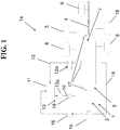
Fig. 1 zeigt ein Funktionsschema einer Prüfvorrichtung, die nicht Teil der vorliegenden Erfindung ist, zur Lastwechselprüfung eines Druckgasspeichers. -
Fig. 2 zeigt eine bevorzugte Ausgestaltung einer Hochdruckpumpe für die Prüfvorrichtung gemäßFig. 1 . - In
Fig. 1 ist eine Ausführungsform einer Prüfvorrichtung 1a zur Durchführung von Lastwechselprüfungen gezeigt. Die Prüfvorrichtung 1a weist einen druckfesten Prüfbehälter 1 auf, welcher mit einem im Wesentlichen inkompressiblen, flüssigen Druckmedium 2 unter Druck befüllt werden kann. Im Inneren des Prüfbehälters 1 wird ein zu prüfender Druckgasspeicher 3 aufgenommen. Der druckfeste Prüfbehälter 1 kann geöffnet und geschlossen werden, so dass der zu prüfende Druckgasspeicher 3 eingesetzt und entnommen werden kann. Der Druckgasspeicher 3 beinhaltet ein Druckgas 7. Das Druckmedium 2 kann Wasser, eine Flüssigkeit mit einem Wasseranteil von 5 % bis weniger als 100 %, insbesondere von 20 % bis 60 % oder eine Hydraulikflüssigkeit auf Mineralölbasis sein. Das Druckgas 7 ist vorzugsweise ein gasförmiges Fluid, insbesondere ein Inertgas oder Brenngas, insbesondere Stickstoff, Helium, Erdgas, insbesondere Wasserstoff, ferner verdichtete Luft oder Sauerstoff. Der druckfeste Prüfbehälter 1 ist für einen Druck von 5 bar bis 2500 bar, vorzugsweise von 500 bar bis 1800 bar, insbesondere von 900 bar bis 1500 bar, ausgelegt. Der Prüfdruck im Druckgasspeicher 3 beträgt von 5 bar bis 2500 bar, vorzugsweise von 500 bar bis 1800 bar, insbesondere von 900 bar bis 1500 bar. - Wie aus
Fig. 1 weiters ersichtlich, weist die Prüfvorrichtung 1a eine durch den druckfesten Prüfbehälter 1 zum Druckgasspeicher 3 führende Druckgaszuleitung 4 auf, mit welcher der Druck des Druckgases 7 im Druckgasspeicher 3 eingestellt werden kann. Ein erstes Druckmessgerät 5 erfasst den Druck des Druckmediums 2 im druckfesten Prüfbehälter 1. Ein zweites Druckmessgerät 6 erfasst den Druck des Druckgases 7 im Druckgasspeicher 3. Ein erstes Temperaturmessgerät 8 erfasst die Temperatur des Druckmediums 2 im druckfesten Prüfbehälter 1. Ein zweites Temperaturmessgerät 9 erfasst die Temperatur des Druckgasspeichers 3. Eine Druckmediumzuleitung 10 verbindet den druckfesten Prüfbehälter 1 mit einem Druckmediumspeicher 11. Weiters ist eine erste Druckmediumableitung 12 vorgesehen, welche den Prüfbehälter 1 mit dem Druckmediumspeicher 11 verbindet. In der ersten Druckmediumableitung 12 ist eine Ventilvorrichtung 12a vorgesehen, mit welchem der Rückfluss des Druckmediums 2 vom Prüfbehälter 1 in den Druckmediumspeicher 11 selektiv freigegeben und unterbrochen werden kann. Zudem kann hiermit der Prüfbehälter entlüftet werden. Der Druckmediumspeicher 11 beinhaltet das Druckmedium 2 und liegt auf Atmosphärendruck. Die Prüfvorrichtung 1a weist zudem in der Druckmediumzuleitung 10 eine Einrichtung 13 zum Erhöhen des Drucks des Druckmediums 2 im Prüfbehälter 1 auf. Als Einrichtung 13 ist in der gezeigten Ausführungsform eine Hochdruckpumpe 13a vorgesehen, mit welcher der Druck des Druckmediums 2 im Prüfbehälter 1 erhöht werden kann. Eine zweite Druckmediumableitung 14 verbindet den Prüfbehälter 1 mit dem Druckmediumspeicher 11, wobei die Druckmediumableitung 14 durch eine weitere Ventilvorrichtung 15 selektiv freigegeben und unterbrochen werden kann. Eine Pumpeinrichtung mit einer Niederdruckpumpe 16 ermöglicht die Entleerung des druckfesten Prüfbehälters 1, indem das Druckmedium 2 in den Druckmediumspeicher 11 geführt wird. - Wie aus
Fig. 1 weiters ersichtlich, ist der Druckgasspeicher 3 in der gezeigten Ausgestaltung an wenigstens einer Stelle, bevorzugt jedoch an drei bis fünf voneinander entfernten Stellen, vorzugsweise an genau drei Stellen, mit jeweils einem Messelement 17 versehen, mit welchem lokale Längenänderungen der Wandung des Druckgasspeichers 3 erfasst werden. Das Messelement 17 ist vorzugsweise als Dehnmessstreifen zur Erfassung von Längenänderungen ausgeführt. Als Referenzwert für die Längenänderung wird jene Messgröße herangezogen, die am Druckgasspeicher 3 im drucklosen Zustand ermittelt wird. Eine Temperiereinheit 18 erlaubt eine Einflussnahme auf die Temperatur des Druckgasspeichers 3 durch Heizen und/oder Kühlen des Druckmediums 2 im Prüfbehälter 1. Eine Durchflussmesseinrichtung 19 misst das Durchflussvolumen des in den Prüfbehälter 1 geförderten Druckmediums 2. Der Messwert für das Durchflussvolumen des Druckmediums 2 kann mit einem Referenzwert verglichen werden, um ein atypisches Verhalten des zu prüfenden Druckgasspeichers 3 festzustellen. - Zum Zweck der Lastwechselprüfung wird der Druckgasspeicher 3 im Inneren des druckfesten Prüfbehälters 1 angeordnet, welcher mit dem Druckmedium befüllt wird. Anschließend wird der Druckgasspeicher 3 von innen mit dem Druckgas 7 druckbeaufschlagt, bis das Druckgas 7 den gewünschten Prüfdruck im Druckgasspeicher 3 erreicht. Durch die Druckbeaufschlagung des Druckgasspeichers 3 wird eine elastische Verformung der Wandung des Druckgasspeichers 3 bewirkt, welche mit den Messelementen 17 erfasst wird. Die Längenänderung ist umso größer, je höher die Druckdifferenz zwischen Druckmedium 2 und Druckgas 7 ist. Im drucklosen Zustand des Druckmediums 2 (d.h. im ausgeschalteten Zustand der Hochdruckpumpe 13a) erreicht die Längenänderung des Druckgasspeichers 3 einen Maximalwert. In der gezeigten Ausführungsform wird anschließend der Druck des inkompressiblen Druckmediums 2 erhöht, so dass der Druckgasspeicher 3 auf der Oberfläche mit (zusätzlichem) Druck beaufschlagt wird. Zu diesem Zweck werden die Ventilvorrichtung 12a in der ersten Druckmediumableitung 12 und die weitere Ventilvorrichtung 15 in der zweiten Druckmediumableitung 14 jeweils in die Schließstellung geschalten während die Hochdruckpumpe 13a aktiv ist, so dass der Druck des Druckmediums 2 innerhalb des Prüfbehälters 1 kontinuierlich erhöht wird. Durch den von außen auf den Druckgasspeicher 3 ausgeübten Druck wird die Längenänderung verglichen zum Maximalwert reduziert, wobei die Messgrößen der Messelemente 17 so nahe als möglich an den vorab ermittelten Urzustand angenähert werden. Im hypothetischen Idealfall wird der Urzustand ohne Abweichung erreicht. In der Praxis sind jedoch bedingt durch Messfehler, Fertigungstoleranzen etc. Abweichungen unvermeidlich, welche beispielsweise weniger als 20 %, insbesondere weniger als 10 %, vorzugsweise weniger als 3 %, betragen. Zur Druckentlastung wird die Ventilvorrichtung 12a geöffnet, wodurch der Druckwert des ersten Druckmessgeräts 5 auf Atmosphärendruck absinkt. Entsprechend der gewünschten Zykluszahl wird der Vorgang der Druckanhebung und -entlastung viele Male, beispielsweise mehr als 100 Mal, insbesondere mehr als 500 Mal, wiederholt. Nach Abschluss der Lastwechselprüfung wird die weitere Ventilvorrichtung 15 geöffnet. Mittels der Niederdruckpumpe 16 wird das Druckmedium 2 aus dem druckfesten Prüfbehälter 1 in den Medienspeicher 11 abgepumpt. Der Druckgasspeicher 3 kann anschließend aus dem entleerten Prüfbehälter 1 entfernt werden, woraufhin die Prüfvorrichtung 1a für die Lastwechselprüfung des nächsten Druckgasspeichers 3 zur Verfügung steht.
- In einer weiteren Ausführungsform wird der Druck des Druckmediums 2 zur Rückbildung der elastischen Verformung des Druckgasspeichers 3 so lange erhöht, bis der Druckwert am ersten Druckmessgerät 5 im Wesentlichen dem Prüfdruck am zweiten Druckmessgerät 6 entspricht.
- In
Fig. 2 ist eine besondere Ausgestaltung der Hochdruckpumpe 13a dargestellt. Die Hochdruckpumpe 13a weist einen Antrieb 20 auf. Dieser Antrieb 20 wirkt auf einen Kolben 21, der in der gezeigten Ausführung über die Druckmediumzuleitung 10 mit dem Prüfbehälter 1 verbunden ist. Die Hochdruckpumpe 13a kann direkt am Prüfbehälter 1 verbaut sein. Der Antrieb 20 ist insbesondere als mechanischer Antrieb, pneumatischer, elektrischer oder hydraulischer Antrieb ausgeführt. Der Kolben 21 ist beweglich im Innenraum eines Gehäuses 22 angeordnet. Wenn der Kolben 21 um einen Hub x verschoben wird, wirkt eine Kolbenfläche 23 des Kolbens 21 auf das Arbeits- bzw. Druckmedium 2 im Prüfbehälter 1. Das Verdrängungsvolumen des Kolbens 21 wird durch das Produkt aus Kolbenfläche 23 und Hub x gebildet. Bei der zyklischen Lastwechselprüfung des Druckgasspeichers 3 wird durch die Variation des Hubs x die erforderliche Volumenänderung für den Druckgasspeicher 3 erwirkt. Wird der Hub x verkleinert, erhöht sich entsprechend der Druck des Druckmediums 2 im Prüfbehälter 1, wodurch die mechanischen Spannungen im Druckgasspeicher 3 verringert werden. Wenn der Hub x des Kolbens 21 im nächsten Schritt vergrößert wird, sinkt der Außendruck auf den Druckgasspeicher 3, so dass die mechanischen Spannungen im Druckgasspeicher 3 erhöht werden. - In einem Ausführungsbeispiel soll ein Druckbehälter 3 in Form eines Wasserstofftanks für ein Kraftfahrzeug über 1000 Zyklen mit einer Lastschwingbreite von 0 bis 1000 bar mit Wasserstoff belastet werden. Entsprechend wird der Druck des Wasserstoffs auf den Prüfdruck von 1000 bar erhöht. Anschließend wird der von außen durch das Druckmedium 2 auf den Druckgasspeicher 3 ausgeübte Druck angehoben, bis die Längenänderung am Druckgasspeicher 3 ein Minimum ergibt. Danach wird der Druck vom Druckmedium 2 auf den Druckgasspeicher 3 auf Atmosphärendruck abgesenkt. Dieser Vorgang wird 1000 Mal durchgeführt.
- Dieses Prüfverfahren kann beispielsweise bei der Produktion von Wasserstoff-Fahrzeugtanks eingesetzt werden, wobei beispielsweise jeder 200. Wasserstoff-Fahrzeugtank mit 1000 Volllastwechseln geprüft wird. Die Gesamtprüfdauer kann dabei gegenüber dem Stand der Technik wesentlich reduziert werden.
- Die Prüfvorrichtung 1 ist darüber hinaus für die Durchführung von Berstversuchen besonders gut geeignet. Dabei wird durch die Druckgaszuleitung 4 der Druck im Druckgasspeicher 3 so lange erhöht, bis der Druckgasspeicher 3 birst. Der Prüfbehälter 1 mit dem Druckmedium 2 dient dabei als Abschirmung, so dass die Sicherheit wesentlich erhöht wird.
Claims (10)
- Verfahren zur Lastwechselprüfung eines Druckgasspeichers (3) mit den Schritten:i. Anordnen des zu prüfenden Druckgasspeichers (3) innerhalb eines Prüfbehälters (1);ii. Erhöhen des Drucks eines Druckgases (7) im Druckgasspeicher (3) auf einen Prüfdruck;iii. Messen einer elastischen Verformung des Druckgasspeichers (3), welche durch den Prüfdruck des Druckgases (7) hervorgerufen wird;iv. Erhöhen des Drucks eines Druckmediums (2) im Prüfbehälter (1), so dass die elastische Verformung des Druckgasspeichers (3) durch den Druck des Druckmediums (2) auf den Druckgasspeicher (3) reduziert wird;v. Absenken des Drucks des Druckmediums (2) im Prüfbehälter (1) ;vi. Wiederholen der Schritte iii. bis v.
- Verfahren nach Anspruch 1, dadurch gekennzeichnet, dass der Druck des Druckmediums (2) im Prüfbehälter (1) so lange erhöht wird, bis eine im Wesentlichen vollständige Rückbildung der elastischen Verformung des Druckgasspeichers (3) gemessen wird.
- Verfahren nach Anspruch 1, dadurch gekennzeichnet, dass der Druck des Druckmediums (2) im Prüfbehälter (1) so lange erhöht wird, bis der Druck des Druckmediums (2) im Prüfbehälter (1) im Wesentlichen dem Prüfdruck des Druckgases (7) im Druckgasspeicher (3) entspricht.
- Verfahren nach einem der Ansprüche 1 bis 3, dadurch gekennzeichnet, dass der zu prüfende Druckgasspeicher (3) in dem Prüfbehälter (1) allseitig von dem Druckmedium (2) umgeben wird.
- Verfahren nach einem der Ansprüche 1 bis 4, dadurch gekennzeichnet, dass die elastische Verformung des Druckgasspeichers (3) mit zumindest einem, vorzugsweise mit zumindest zwei, besonders bevorzugt mit drei, Dehnmessstreifen an dem Druckgasspeicher (3) erfasst wird.
- Verfahren nach einem der Ansprüche 1 bis 5, dadurch gekennzeichnet, dass ein in den Prüfbehälter (1) zufließendes Durchflussvolumen des Druckmediums (2) und/oder ein aus dem Prüfbehälter (1) abfließendes Durchflussvolumen des Druckmediums (2) gemessen wird, um eine Volumenänderung des Druckgasspeichers (3) aus dem zu- bzw. abfließenden Durchflussvolumen des Druckmediums (2) festzustellen.
- Verfahren nach Anspruch 6, gekennzeichnet durch die weiteren Schritte:- Vergleichen der Volumenänderung des Druckgasspeichers (3) mit einem Referenzwert;- Feststellen eines Fehlers des Druckgasspeichers (3), wenn die Volumenänderung des Druckgasspeichers (3) den Referenzwert übersteigt.
- Verfahren nach einem der Ansprüche 1 bis 7, dadurch gekennzeichnet, dass das Druckmedium (2) im Wesentlichen inkompressibel ist, wobei als Druckmedium bevorzugt Wasser, eine Flüssigkeit mit einem Wassergehalt von mehr als 5 Volumenprozent und weniger als 100 Volumenprozent, insbesondere von 20 Volumenprozent bis 60 Volumenprozent, oder eine Hydraulikflüssigkeit verwendet wird.
- Verfahren nach einem der Ansprüche 1 bis 8, dadurch gekennzeichnet, dass die Temperatur des Druckgasspeichers (3) mit einer Temperiereinheit (18) eingestellt wird.
- Verfahren nach einem der Ansprüche 1 bis 9, dadurch gekennzeichnet, dass der Prüfdruck des Druckgases (7) im Druckgasspeicher (3) von 5 bar bis 2500 bar, insbesondere von 500 bar bis 1800 bar, insbesondere von 900 bar bis 1500 bar, beträgt.
Applications Claiming Priority (2)
| Application Number | Priority Date | Filing Date | Title |
|---|---|---|---|
| EP18154376.0A EP3521800A1 (de) | 2018-01-31 | 2018-01-31 | Prüfvorrichtung und verfahren zur lastwechselprüfung |
| PCT/EP2019/052309 WO2019149790A1 (de) | 2018-01-31 | 2019-01-31 | Prüfvorrichtung und verfahren zur lastwechselprüfung |
Publications (2)
| Publication Number | Publication Date |
|---|---|
| EP3746762A1 EP3746762A1 (de) | 2020-12-09 |
| EP3746762B1 true EP3746762B1 (de) | 2021-12-01 |
Family
ID=61132121
Family Applications (2)
| Application Number | Title | Priority Date | Filing Date |
|---|---|---|---|
| EP18154376.0A Withdrawn EP3521800A1 (de) | 2018-01-31 | 2018-01-31 | Prüfvorrichtung und verfahren zur lastwechselprüfung |
| EP19701538.1A Active EP3746762B1 (de) | 2018-01-31 | 2019-01-31 | Prüfvorrichtung und verfahren zur lastwechselprüfung |
Family Applications Before (1)
| Application Number | Title | Priority Date | Filing Date |
|---|---|---|---|
| EP18154376.0A Withdrawn EP3521800A1 (de) | 2018-01-31 | 2018-01-31 | Prüfvorrichtung und verfahren zur lastwechselprüfung |
Country Status (4)
| Country | Link |
|---|---|
| US (1) | US20210041334A1 (de) |
| EP (2) | EP3521800A1 (de) |
| JP (1) | JP2021512298A (de) |
| WO (1) | WO2019149790A1 (de) |
Cited By (1)
| Publication number | Priority date | Publication date | Assignee | Title |
|---|---|---|---|---|
| EP4339586A1 (de) | 2022-09-19 | 2024-03-20 | SincoTec Holding GmbH | Medium-beanspruchungs-prüfeinrichtung |
Families Citing this family (6)
| Publication number | Priority date | Publication date | Assignee | Title |
|---|---|---|---|---|
| DE102019128318A1 (de) * | 2019-10-21 | 2021-04-22 | Audi Ag | Drucktank, System zum Überwachen eines Drucktanks und Kraftfahrzeug |
| KR20210158044A (ko) * | 2020-06-23 | 2021-12-30 | 주식회사 엘지에너지솔루션 | 금속 호일 피로 시험 시스템 및 금속 호일 피로 시험 방법 |
| KR20220037635A (ko) * | 2020-09-18 | 2022-03-25 | 주식회사 엘지에너지솔루션 | 자동차용 전지 모듈 프레임의 내구성 평가 장치 및 평가 방법 |
| CN113405912B (zh) * | 2021-05-27 | 2022-12-16 | 华南理工大学 | 本质安全的高纯高压氢环境材料相容性测试系统及方法 |
| CN113640135A (zh) * | 2021-10-15 | 2021-11-12 | 山东科尔自动化仪表股份有限公司 | 一种仪器生产用外壳变形自动化检测系统 |
| CN113984533B (zh) * | 2021-10-26 | 2023-08-22 | 中国航发沈阳发动机研究所 | 一种构件表面压力加载装置 |
Family Cites Families (11)
| Publication number | Priority date | Publication date | Assignee | Title |
|---|---|---|---|---|
| JPS60162932A (ja) * | 1984-02-03 | 1985-08-24 | Mitsubishi Heavy Ind Ltd | 繰り返し加圧試験装置 |
| JPS6144555U (ja) * | 1984-08-27 | 1986-03-24 | 三菱重工業株式会社 | 繰返し加圧試験装置 |
| GB8601002D0 (en) * | 1986-01-16 | 1986-02-19 | Distillers Co Carbon Dioxide | Pressure testing gas cylinders |
| US6494343B2 (en) * | 2001-02-15 | 2002-12-17 | Advanced Technology Materials, Inc. | Fluid storage and dispensing system featuring ex-situ strain gauge pressure monitoring assembly |
| JP2004012350A (ja) * | 2002-06-07 | 2004-01-15 | Nippon Sanso Corp | 高圧ガス容器の耐圧試験装置及び試験方法 |
| JP2004286586A (ja) * | 2003-03-20 | 2004-10-14 | Sumitomo Metal Ind Ltd | 高圧気体疲労試験方法及び装置 |
| CN101403669A (zh) * | 2008-11-12 | 2009-04-08 | 同济大学 | 全自动高压容器气体循环充放疲劳测试系统 |
| CN101881714A (zh) * | 2009-05-07 | 2010-11-10 | 刘小成 | 变容积外测法气瓶试验装置 |
| KR101148512B1 (ko) * | 2011-12-22 | 2012-05-21 | 한국해양연구원 | 내압실험 시 진동을 이용한 내압용기와 고압챔버 간의 신호전달 장치 및 방법 |
| DE102018115540A1 (de) * | 2017-06-27 | 2018-12-27 | Sabine Rinke | Druckspeichersystem mit Überwachung |
| DE102019128318A1 (de) * | 2019-10-21 | 2021-04-22 | Audi Ag | Drucktank, System zum Überwachen eines Drucktanks und Kraftfahrzeug |
-
2018
- 2018-01-31 EP EP18154376.0A patent/EP3521800A1/de not_active Withdrawn
-
2019
- 2019-01-31 WO PCT/EP2019/052309 patent/WO2019149790A1/de active Search and Examination
- 2019-01-31 US US16/966,772 patent/US20210041334A1/en not_active Abandoned
- 2019-01-31 EP EP19701538.1A patent/EP3746762B1/de active Active
- 2019-01-31 JP JP2020540812A patent/JP2021512298A/ja active Pending
Cited By (1)
| Publication number | Priority date | Publication date | Assignee | Title |
|---|---|---|---|---|
| EP4339586A1 (de) | 2022-09-19 | 2024-03-20 | SincoTec Holding GmbH | Medium-beanspruchungs-prüfeinrichtung |
Also Published As
| Publication number | Publication date |
|---|---|
| US20210041334A1 (en) | 2021-02-11 |
| EP3521800A1 (de) | 2019-08-07 |
| WO2019149790A1 (de) | 2019-08-08 |
| JP2021512298A (ja) | 2021-05-13 |
| EP3746762A1 (de) | 2020-12-09 |
Similar Documents
| Publication | Publication Date | Title |
|---|---|---|
| EP3746762B1 (de) | Prüfvorrichtung und verfahren zur lastwechselprüfung | |
| WO2013007432A1 (de) | Lecksucheinrichtung sowie verfahren zum überprüfen von gegenständen auf dichtigkeit mittels einer lecksucheinrichtung | |
| DE102019001436A1 (de) | Verfahren zum Ermitteln eines Speicherdruckes nebst zugehöriger Vorrichtung | |
| DE2906897C2 (de) | ||
| DE102019113559A1 (de) | Vorrichtung und Verfahren zur Prüfung von Faltenbälgen | |
| DE102017113756A1 (de) | Verfahren und Vorrichtung zur Druckprüfung von beliebigen Prüflingen, deren Volumen mit einer Flüssigkeit gefüllt wird | |
| WO2014082709A2 (de) | Verfahren zur durchführung eines druck- und dichtheitstests | |
| DE102016010657A1 (de) | Spannvorrichtung mit einer Sensoranordnung | |
| DE102014211880A1 (de) | Kraftstoffzuführungssystem und Verfahren zum Lokalisieren eines Lecks in einem Kraftstoffzuführungssystem | |
| DE4427645A1 (de) | Verfahren und Vorrichtung zur Vordrucküberwachung von Ausdehnungsgefäßen | |
| AT515915B1 (de) | Hydrauliksystem | |
| EP3511570A1 (de) | Verfahren zur verdichtung und speicherung eines fluids | |
| DE69325190T2 (de) | Verfahren und Vorrichtung zur Erkennung von ungelöstes Gaz in hydraulische Systemen | |
| DE102013007324A1 (de) | Verfahren und Vorrichtung zur Durchführung einer Dichtigkeitsprüfung eines Flüssiggas-treibstoffsystems eines Kraftfahrzeugs | |
| EP4065878A1 (de) | System mit zumindest zwei kryobehältern zur bereitstellung eines fluids | |
| DE102019120242A1 (de) | Verfahren zum Ermitteln einer Füllmasse eines Druckbehälters | |
| DE4006905A1 (de) | Verfahren zur feststellung der gasvorspannung bei hydrospeichern und zum einhalten eines druck-sollwertes der gasvorlage waehrend des betriebes | |
| WO2015000563A1 (de) | Verfahren zum ermitteln eines wasserstofftankdrucks | |
| DE102018217975A1 (de) | Druckluftanlage sowie Verfahren zur Speicherung von Abluft mit der Druckluftanlage | |
| DE102014115515B3 (de) | Vorrichtung zur Durchführung einer Dichtheitsprüfung eines Differenzdruckmessaufnehmers | |
| DE10305000A1 (de) | Metallbalgdruckspeicher für hydraulische Systeme | |
| EP0599171B1 (de) | Verfahren zur Regelung und/oder Überwachung eines Hydraulikspeichers | |
| DE102017125832B3 (de) | Verfahren zur Detektion eines Fehlers in einem System zur pneumatischen Verstellung eines Stellelements und computerlesbares Speichermedium | |
| EP3390891A1 (de) | Konstantdruckspeichereinheit | |
| DE102004018678B4 (de) | Druckregelvorrichtung |
Legal Events
| Date | Code | Title | Description |
|---|---|---|---|
| STAA | Information on the status of an ep patent application or granted ep patent |
Free format text: STATUS: UNKNOWN |
|
| STAA | Information on the status of an ep patent application or granted ep patent |
Free format text: STATUS: THE INTERNATIONAL PUBLICATION HAS BEEN MADE |
|
| PUAI | Public reference made under article 153(3) epc to a published international application that has entered the european phase |
Free format text: ORIGINAL CODE: 0009012 |
|
| STAA | Information on the status of an ep patent application or granted ep patent |
Free format text: STATUS: REQUEST FOR EXAMINATION WAS MADE |
|
| 17P | Request for examination filed |
Effective date: 20200805 |
|
| AK | Designated contracting states |
Kind code of ref document: A1 Designated state(s): AL AT BE BG CH CY CZ DE DK EE ES FI FR GB GR HR HU IE IS IT LI LT LU LV MC MK MT NL NO PL PT RO RS SE SI SK SM TR |
|
| AX | Request for extension of the european patent |
Extension state: BA ME |
|
| STAA | Information on the status of an ep patent application or granted ep patent |
Free format text: STATUS: EXAMINATION IS IN PROGRESS |
|
| RIC1 | Information provided on ipc code assigned before grant |
Ipc: G01N 3/32 20060101ALI20210216BHEP Ipc: F17C 1/00 20060101ALI20210216BHEP Ipc: G01M 5/00 20060101ALI20210216BHEP Ipc: G01N 3/12 20060101AFI20210216BHEP Ipc: G01M 3/36 20060101ALI20210216BHEP Ipc: F17C 5/06 20060101ALI20210216BHEP |
|
| 17Q | First examination report despatched |
Effective date: 20210224 |
|
| DAV | Request for validation of the european patent (deleted) | ||
| DAX | Request for extension of the european patent (deleted) | ||
| GRAP | Despatch of communication of intention to grant a patent |
Free format text: ORIGINAL CODE: EPIDOSNIGR1 |
|
| STAA | Information on the status of an ep patent application or granted ep patent |
Free format text: STATUS: GRANT OF PATENT IS INTENDED |
|
| INTG | Intention to grant announced |
Effective date: 20210722 |
|
| GRAS | Grant fee paid |
Free format text: ORIGINAL CODE: EPIDOSNIGR3 |
|
| GRAA | (expected) grant |
Free format text: ORIGINAL CODE: 0009210 |
|
| STAA | Information on the status of an ep patent application or granted ep patent |
Free format text: STATUS: THE PATENT HAS BEEN GRANTED |
|
| AK | Designated contracting states |
Kind code of ref document: B1 Designated state(s): AL AT BE BG CH CY CZ DE DK EE ES FI FR GB GR HR HU IE IS IT LI LT LU LV MC MK MT NL NO PL PT RO RS SE SI SK SM TR |
|
| REG | Reference to a national code |
Ref country code: GB Ref legal event code: FG4D Free format text: NOT ENGLISH |
|
| REG | Reference to a national code |
Ref country code: AT Ref legal event code: REF Ref document number: 1452215 Country of ref document: AT Kind code of ref document: T Effective date: 20211215 Ref country code: CH Ref legal event code: EP |
|
| REG | Reference to a national code |
Ref country code: IE Ref legal event code: FG4D Free format text: LANGUAGE OF EP DOCUMENT: GERMAN |
|
| REG | Reference to a national code |
Ref country code: DE Ref legal event code: R096 Ref document number: 502019002917 Country of ref document: DE |
|
| REG | Reference to a national code |
Ref country code: LT Ref legal event code: MG9D |
|
| REG | Reference to a national code |
Ref country code: NL Ref legal event code: MP Effective date: 20211201 |
|
| PG25 | Lapsed in a contracting state [announced via postgrant information from national office to epo] |
Ref country code: RS Free format text: LAPSE BECAUSE OF FAILURE TO SUBMIT A TRANSLATION OF THE DESCRIPTION OR TO PAY THE FEE WITHIN THE PRESCRIBED TIME-LIMIT Effective date: 20211201 Ref country code: LT Free format text: LAPSE BECAUSE OF FAILURE TO SUBMIT A TRANSLATION OF THE DESCRIPTION OR TO PAY THE FEE WITHIN THE PRESCRIBED TIME-LIMIT Effective date: 20211201 Ref country code: FI Free format text: LAPSE BECAUSE OF FAILURE TO SUBMIT A TRANSLATION OF THE DESCRIPTION OR TO PAY THE FEE WITHIN THE PRESCRIBED TIME-LIMIT Effective date: 20211201 Ref country code: BG Free format text: LAPSE BECAUSE OF FAILURE TO SUBMIT A TRANSLATION OF THE DESCRIPTION OR TO PAY THE FEE WITHIN THE PRESCRIBED TIME-LIMIT Effective date: 20220301 |
|
| PG25 | Lapsed in a contracting state [announced via postgrant information from national office to epo] |
Ref country code: SE Free format text: LAPSE BECAUSE OF FAILURE TO SUBMIT A TRANSLATION OF THE DESCRIPTION OR TO PAY THE FEE WITHIN THE PRESCRIBED TIME-LIMIT Effective date: 20211201 Ref country code: PL Free format text: LAPSE BECAUSE OF FAILURE TO SUBMIT A TRANSLATION OF THE DESCRIPTION OR TO PAY THE FEE WITHIN THE PRESCRIBED TIME-LIMIT Effective date: 20211201 Ref country code: NO Free format text: LAPSE BECAUSE OF FAILURE TO SUBMIT A TRANSLATION OF THE DESCRIPTION OR TO PAY THE FEE WITHIN THE PRESCRIBED TIME-LIMIT Effective date: 20220301 Ref country code: LV Free format text: LAPSE BECAUSE OF FAILURE TO SUBMIT A TRANSLATION OF THE DESCRIPTION OR TO PAY THE FEE WITHIN THE PRESCRIBED TIME-LIMIT Effective date: 20211201 Ref country code: HR Free format text: LAPSE BECAUSE OF FAILURE TO SUBMIT A TRANSLATION OF THE DESCRIPTION OR TO PAY THE FEE WITHIN THE PRESCRIBED TIME-LIMIT Effective date: 20211201 Ref country code: GR Free format text: LAPSE BECAUSE OF FAILURE TO SUBMIT A TRANSLATION OF THE DESCRIPTION OR TO PAY THE FEE WITHIN THE PRESCRIBED TIME-LIMIT Effective date: 20220302 |
|
| PG25 | Lapsed in a contracting state [announced via postgrant information from national office to epo] |
Ref country code: NL Free format text: LAPSE BECAUSE OF FAILURE TO SUBMIT A TRANSLATION OF THE DESCRIPTION OR TO PAY THE FEE WITHIN THE PRESCRIBED TIME-LIMIT Effective date: 20211201 |
|
| PG25 | Lapsed in a contracting state [announced via postgrant information from national office to epo] |
Ref country code: SM Free format text: LAPSE BECAUSE OF FAILURE TO SUBMIT A TRANSLATION OF THE DESCRIPTION OR TO PAY THE FEE WITHIN THE PRESCRIBED TIME-LIMIT Effective date: 20211201 Ref country code: SK Free format text: LAPSE BECAUSE OF FAILURE TO SUBMIT A TRANSLATION OF THE DESCRIPTION OR TO PAY THE FEE WITHIN THE PRESCRIBED TIME-LIMIT Effective date: 20211201 Ref country code: RO Free format text: LAPSE BECAUSE OF FAILURE TO SUBMIT A TRANSLATION OF THE DESCRIPTION OR TO PAY THE FEE WITHIN THE PRESCRIBED TIME-LIMIT Effective date: 20211201 Ref country code: PT Free format text: LAPSE BECAUSE OF FAILURE TO SUBMIT A TRANSLATION OF THE DESCRIPTION OR TO PAY THE FEE WITHIN THE PRESCRIBED TIME-LIMIT Effective date: 20220401 Ref country code: ES Free format text: LAPSE BECAUSE OF FAILURE TO SUBMIT A TRANSLATION OF THE DESCRIPTION OR TO PAY THE FEE WITHIN THE PRESCRIBED TIME-LIMIT Effective date: 20211201 Ref country code: EE Free format text: LAPSE BECAUSE OF FAILURE TO SUBMIT A TRANSLATION OF THE DESCRIPTION OR TO PAY THE FEE WITHIN THE PRESCRIBED TIME-LIMIT Effective date: 20211201 Ref country code: CZ Free format text: LAPSE BECAUSE OF FAILURE TO SUBMIT A TRANSLATION OF THE DESCRIPTION OR TO PAY THE FEE WITHIN THE PRESCRIBED TIME-LIMIT Effective date: 20211201 |
|
| REG | Reference to a national code |
Ref country code: DE Ref legal event code: R119 Ref document number: 502019002917 Country of ref document: DE |
|
| PG25 | Lapsed in a contracting state [announced via postgrant information from national office to epo] |
Ref country code: MC Free format text: LAPSE BECAUSE OF FAILURE TO SUBMIT A TRANSLATION OF THE DESCRIPTION OR TO PAY THE FEE WITHIN THE PRESCRIBED TIME-LIMIT Effective date: 20211201 |
|
| REG | Reference to a national code |
Ref country code: CH Ref legal event code: PL |
|
| PG25 | Lapsed in a contracting state [announced via postgrant information from national office to epo] |
Ref country code: IS Free format text: LAPSE BECAUSE OF FAILURE TO SUBMIT A TRANSLATION OF THE DESCRIPTION OR TO PAY THE FEE WITHIN THE PRESCRIBED TIME-LIMIT Effective date: 20220401 |
|
| REG | Reference to a national code |
Ref country code: BE Ref legal event code: MM Effective date: 20220131 |
|
| PLBE | No opposition filed within time limit |
Free format text: ORIGINAL CODE: 0009261 |
|
| STAA | Information on the status of an ep patent application or granted ep patent |
Free format text: STATUS: NO OPPOSITION FILED WITHIN TIME LIMIT |
|
| PG25 | Lapsed in a contracting state [announced via postgrant information from national office to epo] |
Ref country code: LU Free format text: LAPSE BECAUSE OF NON-PAYMENT OF DUE FEES Effective date: 20220131 Ref country code: DK Free format text: LAPSE BECAUSE OF FAILURE TO SUBMIT A TRANSLATION OF THE DESCRIPTION OR TO PAY THE FEE WITHIN THE PRESCRIBED TIME-LIMIT Effective date: 20211201 Ref country code: DE Free format text: LAPSE BECAUSE OF NON-PAYMENT OF DUE FEES Effective date: 20220802 Ref country code: AL Free format text: LAPSE BECAUSE OF FAILURE TO SUBMIT A TRANSLATION OF THE DESCRIPTION OR TO PAY THE FEE WITHIN THE PRESCRIBED TIME-LIMIT Effective date: 20211201 |
|
| 26N | No opposition filed |
Effective date: 20220902 |
|
| PG25 | Lapsed in a contracting state [announced via postgrant information from national office to epo] |
Ref country code: SI Free format text: LAPSE BECAUSE OF FAILURE TO SUBMIT A TRANSLATION OF THE DESCRIPTION OR TO PAY THE FEE WITHIN THE PRESCRIBED TIME-LIMIT Effective date: 20211201 Ref country code: FR Free format text: LAPSE BECAUSE OF NON-PAYMENT OF DUE FEES Effective date: 20220201 Ref country code: BE Free format text: LAPSE BECAUSE OF NON-PAYMENT OF DUE FEES Effective date: 20220131 |
|
| PG25 | Lapsed in a contracting state [announced via postgrant information from national office to epo] |
Ref country code: LI Free format text: LAPSE BECAUSE OF NON-PAYMENT OF DUE FEES Effective date: 20220131 Ref country code: CH Free format text: LAPSE BECAUSE OF NON-PAYMENT OF DUE FEES Effective date: 20220131 |
|
| PG25 | Lapsed in a contracting state [announced via postgrant information from national office to epo] |
Ref country code: IE Free format text: LAPSE BECAUSE OF NON-PAYMENT OF DUE FEES Effective date: 20220131 |
|
| PG25 | Lapsed in a contracting state [announced via postgrant information from national office to epo] |
Ref country code: IT Free format text: LAPSE BECAUSE OF FAILURE TO SUBMIT A TRANSLATION OF THE DESCRIPTION OR TO PAY THE FEE WITHIN THE PRESCRIBED TIME-LIMIT Effective date: 20211201 |
|
| GBPC | Gb: european patent ceased through non-payment of renewal fee |
Effective date: 20230131 |
|
| PG25 | Lapsed in a contracting state [announced via postgrant information from national office to epo] |
Ref country code: GB Free format text: LAPSE BECAUSE OF NON-PAYMENT OF DUE FEES Effective date: 20230131 |
|
| PG25 | Lapsed in a contracting state [announced via postgrant information from national office to epo] |
Ref country code: MK Free format text: LAPSE BECAUSE OF FAILURE TO SUBMIT A TRANSLATION OF THE DESCRIPTION OR TO PAY THE FEE WITHIN THE PRESCRIBED TIME-LIMIT Effective date: 20211201 Ref country code: CY Free format text: LAPSE BECAUSE OF FAILURE TO SUBMIT A TRANSLATION OF THE DESCRIPTION OR TO PAY THE FEE WITHIN THE PRESCRIBED TIME-LIMIT Effective date: 20211201 |
|
| PG25 | Lapsed in a contracting state [announced via postgrant information from national office to epo] |
Ref country code: HU Free format text: LAPSE BECAUSE OF FAILURE TO SUBMIT A TRANSLATION OF THE DESCRIPTION OR TO PAY THE FEE WITHIN THE PRESCRIBED TIME-LIMIT; INVALID AB INITIO Effective date: 20190131 |