EP3746708B1 - Liquid impermeable switching device - Google Patents
Liquid impermeable switching device Download PDFInfo
- Publication number
- EP3746708B1 EP3746708B1 EP18911552.0A EP18911552A EP3746708B1 EP 3746708 B1 EP3746708 B1 EP 3746708B1 EP 18911552 A EP18911552 A EP 18911552A EP 3746708 B1 EP3746708 B1 EP 3746708B1
- Authority
- EP
- European Patent Office
- Prior art keywords
- switch
- trigger
- harness
- liquid impermeable
- cable
- Prior art date
- Legal status (The legal status is an assumption and is not a legal conclusion. Google has not performed a legal analysis and makes no representation as to the accuracy of the status listed.)
- Active
Links
Images


Classifications
-
- F—MECHANICAL ENGINEERING; LIGHTING; HEATING; WEAPONS; BLASTING
- F24—HEATING; RANGES; VENTILATING
- F24C—DOMESTIC STOVES OR RANGES ; DETAILS OF DOMESTIC STOVES OR RANGES, OF GENERAL APPLICATION
- F24C3/00—Stoves or ranges for gaseous fuels
- F24C3/12—Arrangement or mounting of control or safety devices
- F24C3/126—Arrangement or mounting of control or safety devices on ranges
-
- H—ELECTRICITY
- H01—ELECTRIC ELEMENTS
- H01H—ELECTRIC SWITCHES; RELAYS; SELECTORS; EMERGENCY PROTECTIVE DEVICES
- H01H3/00—Mechanisms for operating contacts
- H01H3/02—Operating parts, i.e. for operating driving mechanism by a mechanical force external to the switch
- H01H3/0206—Combined operation of electric switch and of fluid control device
Definitions
- the product of the present invention relates to a liquid impermeable switch chain/harness with cable which is developed to prevent leakage of liquid into the trigger mechanism in the inner structure of the gas valves.
- the utility model application numbered TR2015/05131 and titled “Innovation in ignition switches” relates to innovation in ignition switches which are mounted on the gas valve in gas furnaces and which provide automatic ignition when the gas is turned on.
- the said application relates to an ignition switch that allows ignition to be achieved when the gas is turned on.
- the ignition switch in the prior art has a spring system in the upper body which goes out of the body through an opening, and this causes oils, soapsuds, etc. to enter into the switch and contact the ignition, and results in short circuit causing the switch to fail.
- Another switch is known from WO2016/039703 A1 .
- the present invention relates to a liquid impermeable switch chain/harness with cable developed to eliminate the above mentioned disadvantages and bring new advantages to the concerned technical field.
- the product of the invention is to change the contact structure of the gas valves used in stoves, hobs, cookers and ovens.
- the inner part of the existing contact structures is quite unprotected, and when liquid leaks into the contact, oxidation occurs upon contact of the copper switch with liquid.
- Technical innovations have been made as described below to prevent this oxidation.
- the objective of the present invention is to ensure that the liquid-impermeable switch chain/harness with cable of the gas valve provides sealing to the area where the switch is located to prevent corrosion of the switch due to liquid contact.
- Another objective of the invention is to design the trigger and the lower trigger in the form of a telescopic system to prevent passage of liquid through the upper body.
- Another objective of the invention is to remove the lower body connection lug slots provided on the upper body from inside of the upper body and to place them on the outer side, and thus to protect the switch from the liquid flow passing through the lug slots provided on the upper body.
- a further objective of the invention is to prevent the flow of liquid through the cable channels by moving the cable channels located on the first switch terminal to the lowest possible part.
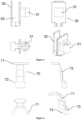
- the first switch spring (40) is a complementary part of the ignition mechanism and it supports up and down movement of the trigger (70).
- the contact terminal (50) is a part; which includes electricity connection thereon; connects the trigger (70) mechanism with the first switch spring (40), trigger lower mechanism (30), switch (20) and the second switch spring (10); and complements the ignition system.
- the cable channel (51) is a structure which is located on the switch terminal (50) and allows the cables to pass through it and be squeezed to prevent liquid flow into the mechanism.
- the lower body (60) is the structure that carries the system thereon.
- the lower body lug (61) is an outward protrusion which is located on the lower part of the lower body side surfaces and which enables to mount and lock the lower body (60) on the upper body (80).
- the lower body cable channel (62) is the clearance provided for the cable connection of electricity to the switch terminal (50).
- the first switch spring housing (63) is a channel which is located in the inner part of the lower body (60) and into which the first switch spring (40) is disposed.
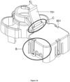
- the trigger (70) is a part which actuates the ignition mechanism from outside and can move up and down to enable all the ignition members inside to interact with each other and to be deactivated. When it is connected with the trigger lower mechanism, it becomes a part which prevents leakage of liquid to the inner part of the liquid impermeable switch chain/harness with cable and which, at the same time, can clean the food residues that may accumulate at the right and left of the trigger by means of the lugs provided on the right and left surfaces thereof.
- the crescent trigger (71) is in the form of a crescent around the gas valve shaft and it is not mounted to the gas valve shaft.
- the trigger lug (72) is the part which fits into the channel on the upper body (80) and which both cleans the food residues and limits operation of the trigger in a certain range.
- the crescent trigger (71) is the part which limits downward movement of the plastic ring (90) and which provides movement to the trigger when it reaches the limit.
- the lower trigger engagement housing (74) is the part which, upon being connected with the upper trigger engagement channel (33), prevents leakage of liquid into the body from the top.
- This integrated structure passes the liquid flow coming from the top part around itself to prevent it from reaching the switch (20), switch terminal (50) and second and first switch springs (10, 40).
- the upper body (80) is the piece which protects the structure in itself and forms the outer part of the structure upon being connected with the lower body (60).
- the cable channel (81) is a cavity-shaped structure which is located on the side surfaces of the upper body (80), allows the passage of the cables and has the maximum height to prevent liquid passage into the structure through the said parts.
- the valve lock (82) is a part of the upper body (80), and it is the piece that enables the liquid impermeable switch chain/harness with cable to be mounted to the valve shaft.
- the upper body neck (83) is the part through which the gas valve shaft passes.
- the trigger channel (84) is a channel through which the trigger (70) passes and which extends downward from the upper body
- Lower body lug slot (85) is a structure; to which the lower body lug (61) is inserted and which connects the lower and upper bodes to each other; and which is designed in the form of a protrusion on the side surface of the upper body (80) and does not have any opening in the rear part thereof that enables access to the inner structure.
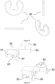
- the lug channels and the cable channels located on the side walls of the body in the state of the art shown with detail B in Figure 16 allow passage of the liquids into the switch.
- This problem is addressed in the present invention by positioning the lower body engagement housing (85) at the outside of the lower body (60) such that a gap is not formed on the inner surface, and thus contact of the liquid with the switch (20) is prevented.
- the cable channel (81) located on the side surfaces of the upper body (80) is lowered, and additionally, the lower body cable channel (62) in the lower body (60) is raised so that entry of liquid through this part into the liquid impermeable switch chain/harness with cable is prevented.
- the cable channel (51) located on the switch terminal is narrowed down; and by producing this product from a soft material, a natural o-ring system is formed by fitting the cable into the cable channel (51), and thus an extra barrier which prevents liquid flow into the structure is formed.
- the lower trigger engagement housing (74) located at the lower part of the trigger (70) cleans the food residues accumulated on the sides of the upper body (80) by moving within the channel provided on the upper body.
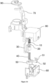
- the switch terminal (50) produced in compliance with the channels in the lower body (60) is placed into the lower body (60). Then, the first switch spring (40) is inserted into the inner part of the switch terminal (50) and into the first switch spring housing (63) located on the lower body (60). The lower portion of the switch housing (31) of the trigger lower mechanism (30) is disposed such that it is placed over the first switch spring (40). The switch (20) is placed in the upper part of the switch housing (31) of the trigger lower mechanism (30). On the upper part of the switch (20), the second switch spring (10) is mounted on which the upper body (80) is mounted.
- the lower body lug (61) is attached to the lower body lug slot (85), which is located on the upper body (80) and which is useful for locking the lower body (60), and hence the mechanism is locked and fixed.
- the trigger channel (84) on the trigger (70) is engaged to the shaft spline (32) and thus entire assembly of the system is completed and it is made ready for being mounted to the gas valve.
- one plastic ring (90) attached to the gas valve shaft and this plastic ring (90) is used to provide movement to the trigger (70) upon receiving the downward movement of the gas valve shaft with the crescent trigger (71).
- the plastic ring (90) mounted to the gas valve shaft rotates with a movement equivalent to the right and left movement of the gas valve shaft to turn on the gas. Regardless of the direction and amount of this rotation angle, the plastic ring (90) provides an uninterrupted contact on the downward movement of the crescent trigger (71) and gas valve shaft.
- the water flows from the outside of the trigger engagement housing upon preventing entry of the water into the switch by means of a trigger engagement housing which is fitted over the part of the switch shaft that protrudes from the body; which switch shaft enables switching by its downward movement and is supported by two springs.
Landscapes
- Engineering & Computer Science (AREA)
- Chemical & Material Sciences (AREA)
- Combustion & Propulsion (AREA)
- Mechanical Engineering (AREA)
- General Engineering & Computer Science (AREA)
- Mechanically-Actuated Valves (AREA)
- Insulated Conductors (AREA)
Applications Claiming Priority (2)
| Application Number | Priority Date | Filing Date | Title |
|---|---|---|---|
| TR201801460 | 2018-02-02 | ||
| PCT/TR2018/050771 WO2019190424A2 (en) | 2018-02-02 | 2018-12-06 | Liquid impermeable switch chain/harness with cable |
Publications (3)
| Publication Number | Publication Date |
|---|---|
| EP3746708A2 EP3746708A2 (en) | 2020-12-09 |
| EP3746708A4 EP3746708A4 (en) | 2021-11-03 |
| EP3746708B1 true EP3746708B1 (en) | 2025-04-09 |
Family
ID=68060702
Family Applications (1)
| Application Number | Title | Priority Date | Filing Date |
|---|---|---|---|
| EP18911552.0A Active EP3746708B1 (en) | 2018-02-02 | 2018-12-06 | Liquid impermeable switching device |
Country Status (3)
| Country | Link |
|---|---|
| EP (1) | EP3746708B1 (pl) |
| PL (1) | PL3746708T3 (pl) |
| WO (1) | WO2019190424A2 (pl) |
Family Cites Families (7)
| Publication number | Priority date | Publication date | Assignee | Title |
|---|---|---|---|---|
| IT247355Y1 (it) * | 1999-07-02 | 2002-07-09 | Lamberti Silvano | Rubinetto per gas con interruttore elettrico incorporato. |
| ITTO20070306A1 (it) * | 2007-05-04 | 2008-11-05 | Itw Ind Components S R L Co N | Dispositivo di comando includente un rubinetto gas ed un elemento di catenaria per bruciatori di un piano di cottura |
| CN201265899Y (zh) * | 2008-08-28 | 2009-07-01 | 宁波方太厨具有限公司 | 一种燃气灶上旋钮开关的防水结构 |
| EP2390575B1 (de) * | 2010-05-24 | 2018-01-03 | BSH Hausgeräte GmbH | Gasventil mit einem Betätigungselement für einen elektrischen Schalter |
| EP3175176B1 (en) * | 2014-07-29 | 2019-10-02 | Castfutura S.p.A. | Flame ignition control device for burners or the like |
| WO2016039703A1 (en) * | 2014-09-11 | 2016-03-17 | Ferel Elektroni̇k Sanayi̇ Ti̇caret Anoni̇m Şi̇rketi̇ | Ignition mechanism for furnace units |
| WO2016134758A1 (en) * | 2015-02-25 | 2016-09-01 | Arcelik Anonim Sirketi | Ignition switch assembly and gas cooking appliance having the same |
-
2018
- 2018-12-06 PL PL18911552.0T patent/PL3746708T3/pl unknown
- 2018-12-06 WO PCT/TR2018/050771 patent/WO2019190424A2/en not_active Ceased
- 2018-12-06 EP EP18911552.0A patent/EP3746708B1/en active Active
Also Published As
| Publication number | Publication date |
|---|---|
| WO2019190424A3 (en) | 2019-12-12 |
| PL3746708T3 (pl) | 2025-10-13 |
| EP3746708A4 (en) | 2021-11-03 |
| EP3746708A2 (en) | 2020-12-09 |
| WO2019190424A2 (en) | 2019-10-03 |
Similar Documents
| Publication | Publication Date | Title |
|---|---|---|
| EP2979035B1 (en) | Waterproof structure of operating device of gas stove and gas stove | |
| CN103629429B (zh) | 探测和传输龙头阀位置的系统以及方法 | |
| EP3318163B1 (en) | Excess pressure protection switch and pressure appliance provided with same | |
| CA2459088A1 (en) | Leak-resistant solenoid valve | |
| KR101901472B1 (ko) | 가정용 기기, 특히 세척기용 넘침-방지 안전 장치 | |
| CN106537008A (zh) | 阀装置 | |
| EP3746708B1 (en) | Liquid impermeable switching device | |
| CN211533944U (zh) | 烹饪设备 | |
| US20120061214A1 (en) | Switch | |
| EP3175176B1 (en) | Flame ignition control device for burners or the like | |
| KR20090014262A (ko) | 감지식 수전 | |
| EP3414477B1 (en) | Electric valve device, particularly for household electrical appliances | |
| JP7345216B2 (ja) | 排水栓装置 | |
| JP6289414B2 (ja) | 調理器 | |
| EP3933272B1 (en) | Gas stove | |
| KR101965664B1 (ko) | 전기 밥솥의 뚜껑 닫힘 방지 장치 | |
| JP2019056229A (ja) | 排水栓装置 | |
| CN107019421A (zh) | 家用电器保温盖板防漏装结构组件及家用电器 | |
| JP7226794B2 (ja) | 排水栓装置 | |
| GB2193563A (en) | Liquid heater | |
| CN213464724U (zh) | 压力烹饪器具的盖体组件、压力烹饪器具和密封件 | |
| EP2430366A2 (en) | Fume-discharge device for boilers | |
| US9770155B2 (en) | Component for feeding a pressurized liquid to a washing tub of a washing machine, in particular a dishwasher | |
| CN223143312U (zh) | 烹饪器具 | |
| CN110248578B (zh) | 小型家用电器 |
Legal Events
| Date | Code | Title | Description |
|---|---|---|---|
| STAA | Information on the status of an ep patent application or granted ep patent |
Free format text: STATUS: THE INTERNATIONAL PUBLICATION HAS BEEN MADE |
|
| PUAI | Public reference made under article 153(3) epc to a published international application that has entered the european phase |
Free format text: ORIGINAL CODE: 0009012 |
|
| STAA | Information on the status of an ep patent application or granted ep patent |
Free format text: STATUS: REQUEST FOR EXAMINATION WAS MADE |
|
| 17P | Request for examination filed |
Effective date: 20200902 |
|
| AK | Designated contracting states |
Kind code of ref document: A2 Designated state(s): AL AT BE BG CH CY CZ DE DK EE ES FI FR GB GR HR HU IE IS IT LI LT LU LV MC MK MT NL NO PL PT RO RS SE SI SK SM TR |
|
| AX | Request for extension of the european patent |
Extension state: BA ME |
|
| DAV | Request for validation of the european patent (deleted) | ||
| DAX | Request for extension of the european patent (deleted) | ||
| REG | Reference to a national code |
Ref country code: DE Ref legal event code: R079 Free format text: PREVIOUS MAIN CLASS: F24C0003000000 Ipc: F24C0003120000 Ref document number: 602018081060 Country of ref document: DE |
|
| A4 | Supplementary search report drawn up and despatched |
Effective date: 20210930 |
|
| RIC1 | Information provided on ipc code assigned before grant |
Ipc: H01H 3/02 20060101ALI20210924BHEP Ipc: F24C 3/12 20060101AFI20210924BHEP |
|
| GRAP | Despatch of communication of intention to grant a patent |
Free format text: ORIGINAL CODE: EPIDOSNIGR1 |
|
| STAA | Information on the status of an ep patent application or granted ep patent |
Free format text: STATUS: GRANT OF PATENT IS INTENDED |
|
| INTG | Intention to grant announced |
Effective date: 20241011 |
|
| GRAJ | Information related to disapproval of communication of intention to grant by the applicant or resumption of examination proceedings by the epo deleted |
Free format text: ORIGINAL CODE: EPIDOSDIGR1 |
|
| STAA | Information on the status of an ep patent application or granted ep patent |
Free format text: STATUS: REQUEST FOR EXAMINATION WAS MADE |
|
| GRAP | Despatch of communication of intention to grant a patent |
Free format text: ORIGINAL CODE: EPIDOSNIGR1 |
|
| STAA | Information on the status of an ep patent application or granted ep patent |
Free format text: STATUS: GRANT OF PATENT IS INTENDED |
|
| GRAS | Grant fee paid |
Free format text: ORIGINAL CODE: EPIDOSNIGR3 |
|
| GRAA | (expected) grant |
Free format text: ORIGINAL CODE: 0009210 |
|
| STAA | Information on the status of an ep patent application or granted ep patent |
Free format text: STATUS: THE PATENT HAS BEEN GRANTED |
|
| INTC | Intention to grant announced (deleted) | ||
| INTG | Intention to grant announced |
Effective date: 20250220 |
|
| AK | Designated contracting states |
Kind code of ref document: B1 Designated state(s): AL AT BE BG CH CY CZ DE DK EE ES FI FR GB GR HR HU IE IS IT LI LT LU LV MC MK MT NL NO PL PT RO RS SE SI SK SM TR |
|
| REG | Reference to a national code |
Ref country code: GB Ref legal event code: FG4D |
|
| REG | Reference to a national code |
Ref country code: CH Ref legal event code: EP |
|
| REG | Reference to a national code |
Ref country code: DE Ref legal event code: R096 Ref document number: 602018081060 Country of ref document: DE |
|
| REG | Reference to a national code |
Ref country code: IE Ref legal event code: FG4D |
|
| REG | Reference to a national code |
Ref country code: NL Ref legal event code: MP Effective date: 20250409 |
|
| PG25 | Lapsed in a contracting state [announced via postgrant information from national office to epo] |
Ref country code: NL Free format text: LAPSE BECAUSE OF FAILURE TO SUBMIT A TRANSLATION OF THE DESCRIPTION OR TO PAY THE FEE WITHIN THE PRESCRIBED TIME-LIMIT Effective date: 20250409 |
|
| REG | Reference to a national code |
Ref country code: AT Ref legal event code: MK05 Ref document number: 1783809 Country of ref document: AT Kind code of ref document: T Effective date: 20250409 |
|
| PG25 | Lapsed in a contracting state [announced via postgrant information from national office to epo] |
Ref country code: FI Free format text: LAPSE BECAUSE OF FAILURE TO SUBMIT A TRANSLATION OF THE DESCRIPTION OR TO PAY THE FEE WITHIN THE PRESCRIBED TIME-LIMIT Effective date: 20250409 Ref country code: PT Free format text: LAPSE BECAUSE OF FAILURE TO SUBMIT A TRANSLATION OF THE DESCRIPTION OR TO PAY THE FEE WITHIN THE PRESCRIBED TIME-LIMIT Effective date: 20250811 Ref country code: ES Free format text: LAPSE BECAUSE OF FAILURE TO SUBMIT A TRANSLATION OF THE DESCRIPTION OR TO PAY THE FEE WITHIN THE PRESCRIBED TIME-LIMIT Effective date: 20250409 |
|
| REG | Reference to a national code |
Ref country code: LT Ref legal event code: MG9D |
|
| PG25 | Lapsed in a contracting state [announced via postgrant information from national office to epo] |
Ref country code: GR Free format text: LAPSE BECAUSE OF FAILURE TO SUBMIT A TRANSLATION OF THE DESCRIPTION OR TO PAY THE FEE WITHIN THE PRESCRIBED TIME-LIMIT Effective date: 20250710 Ref country code: NO Free format text: LAPSE BECAUSE OF FAILURE TO SUBMIT A TRANSLATION OF THE DESCRIPTION OR TO PAY THE FEE WITHIN THE PRESCRIBED TIME-LIMIT Effective date: 20250709 |
|
| PG25 | Lapsed in a contracting state [announced via postgrant information from national office to epo] |
Ref country code: HR Free format text: LAPSE BECAUSE OF FAILURE TO SUBMIT A TRANSLATION OF THE DESCRIPTION OR TO PAY THE FEE WITHIN THE PRESCRIBED TIME-LIMIT Effective date: 20250409 |
|
| PG25 | Lapsed in a contracting state [announced via postgrant information from national office to epo] |
Ref country code: AT Free format text: LAPSE BECAUSE OF FAILURE TO SUBMIT A TRANSLATION OF THE DESCRIPTION OR TO PAY THE FEE WITHIN THE PRESCRIBED TIME-LIMIT Effective date: 20250409 |
|
| PG25 | Lapsed in a contracting state [announced via postgrant information from national office to epo] |
Ref country code: RS Free format text: LAPSE BECAUSE OF FAILURE TO SUBMIT A TRANSLATION OF THE DESCRIPTION OR TO PAY THE FEE WITHIN THE PRESCRIBED TIME-LIMIT Effective date: 20250709 |
|
| PG25 | Lapsed in a contracting state [announced via postgrant information from national office to epo] |
Ref country code: IS Free format text: LAPSE BECAUSE OF FAILURE TO SUBMIT A TRANSLATION OF THE DESCRIPTION OR TO PAY THE FEE WITHIN THE PRESCRIBED TIME-LIMIT Effective date: 20250809 |
|
| PG25 | Lapsed in a contracting state [announced via postgrant information from national office to epo] |
Ref country code: LV Free format text: LAPSE BECAUSE OF FAILURE TO SUBMIT A TRANSLATION OF THE DESCRIPTION OR TO PAY THE FEE WITHIN THE PRESCRIBED TIME-LIMIT Effective date: 20250409 |
|
| REG | Reference to a national code |
Ref country code: DE Ref legal event code: R097 Ref document number: 602018081060 Country of ref document: DE |
|
| PG25 | Lapsed in a contracting state [announced via postgrant information from national office to epo] |
Ref country code: DK Free format text: LAPSE BECAUSE OF FAILURE TO SUBMIT A TRANSLATION OF THE DESCRIPTION OR TO PAY THE FEE WITHIN THE PRESCRIBED TIME-LIMIT Effective date: 20250409 Ref country code: SM Free format text: LAPSE BECAUSE OF FAILURE TO SUBMIT A TRANSLATION OF THE DESCRIPTION OR TO PAY THE FEE WITHIN THE PRESCRIBED TIME-LIMIT Effective date: 20250409 |
|
| PGFP | Annual fee paid to national office [announced via postgrant information from national office to epo] |
Ref country code: IT Payment date: 20251218 Year of fee payment: 8 |
|
| PG25 | Lapsed in a contracting state [announced via postgrant information from national office to epo] |
Ref country code: CZ Free format text: LAPSE BECAUSE OF FAILURE TO SUBMIT A TRANSLATION OF THE DESCRIPTION OR TO PAY THE FEE WITHIN THE PRESCRIBED TIME-LIMIT Effective date: 20250409 |
|
| PGFP | Annual fee paid to national office [announced via postgrant information from national office to epo] |
Ref country code: BG Payment date: 20251223 Year of fee payment: 8 Ref country code: PL Payment date: 20251205 Year of fee payment: 8 |
|
| PG25 | Lapsed in a contracting state [announced via postgrant information from national office to epo] |
Ref country code: EE Free format text: LAPSE BECAUSE OF FAILURE TO SUBMIT A TRANSLATION OF THE DESCRIPTION OR TO PAY THE FEE WITHIN THE PRESCRIBED TIME-LIMIT Effective date: 20250409 |
|
| PG25 | Lapsed in a contracting state [announced via postgrant information from national office to epo] |
Ref country code: RO Free format text: LAPSE BECAUSE OF FAILURE TO SUBMIT A TRANSLATION OF THE DESCRIPTION OR TO PAY THE FEE WITHIN THE PRESCRIBED TIME-LIMIT Effective date: 20250409 Ref country code: SK Free format text: LAPSE BECAUSE OF FAILURE TO SUBMIT A TRANSLATION OF THE DESCRIPTION OR TO PAY THE FEE WITHIN THE PRESCRIBED TIME-LIMIT Effective date: 20250409 |
|
| PLBE | No opposition filed within time limit |
Free format text: ORIGINAL CODE: 0009261 |
|
| STAA | Information on the status of an ep patent application or granted ep patent |
Free format text: STATUS: NO OPPOSITION FILED WITHIN TIME LIMIT |
|
| REG | Reference to a national code |
Ref country code: CH Ref legal event code: L10 Free format text: ST27 STATUS EVENT CODE: U-0-0-L10-L00 (AS PROVIDED BY THE NATIONAL OFFICE) Effective date: 20260218 |
|
| 26N | No opposition filed |
Effective date: 20260112 |