EP3746407B1 - Gasrückgewinnung aus abwasser - Google Patents
Gasrückgewinnung aus abwasser Download PDFInfo
- Publication number
- EP3746407B1 EP3746407B1 EP19714855.4A EP19714855A EP3746407B1 EP 3746407 B1 EP3746407 B1 EP 3746407B1 EP 19714855 A EP19714855 A EP 19714855A EP 3746407 B1 EP3746407 B1 EP 3746407B1
- Authority
- EP
- European Patent Office
- Prior art keywords
- compartment
- membrane
- wastewater
- ion exchange
- alkaline
- Prior art date
- Legal status (The legal status is an assumption and is not a legal conclusion. Google has not performed a legal analysis and makes no representation as to the accuracy of the status listed.)
- Active
Links
Images


Classifications
-
- C—CHEMISTRY; METALLURGY
- C02—TREATMENT OF WATER, WASTE WATER, SEWAGE, OR SLUDGE
- C02F—TREATMENT OF WATER, WASTE WATER, SEWAGE, OR SLUDGE
- C02F1/00—Treatment of water, waste water, or sewage
- C02F1/46—Treatment of water, waste water, or sewage by electrochemical methods
- C02F1/469—Treatment of water, waste water, or sewage by electrochemical methods by electrochemical separation, e.g. by electro-osmosis, electrodialysis, electrophoresis
- C02F1/4693—Treatment of water, waste water, or sewage by electrochemical methods by electrochemical separation, e.g. by electro-osmosis, electrodialysis, electrophoresis electrodialysis
-
- B—PERFORMING OPERATIONS; TRANSPORTING
- B01—PHYSICAL OR CHEMICAL PROCESSES OR APPARATUS IN GENERAL
- B01D—SEPARATION
- B01D19/00—Degasification of liquids
- B01D19/0031—Degasification of liquids by filtration
-
- B—PERFORMING OPERATIONS; TRANSPORTING
- B01—PHYSICAL OR CHEMICAL PROCESSES OR APPARATUS IN GENERAL
- B01D—SEPARATION
- B01D61/00—Processes of separation using semi-permeable membranes, e.g. dialysis, osmosis or ultrafiltration; Apparatus, accessories or auxiliary operations specially adapted therefor
- B01D61/36—Pervaporation; Membrane distillation; Liquid permeation
- B01D61/362—Pervaporation
-
- B—PERFORMING OPERATIONS; TRANSPORTING
- B01—PHYSICAL OR CHEMICAL PROCESSES OR APPARATUS IN GENERAL
- B01D—SEPARATION
- B01D61/00—Processes of separation using semi-permeable membranes, e.g. dialysis, osmosis or ultrafiltration; Apparatus, accessories or auxiliary operations specially adapted therefor
- B01D61/42—Electrodialysis; Electro-osmosis ; Electro-ultrafiltration; Membrane capacitive deionization
- B01D61/44—Ion-selective electrodialysis
- B01D61/445—Ion-selective electrodialysis with bipolar membranes; Water splitting
-
- B—PERFORMING OPERATIONS; TRANSPORTING
- B01—PHYSICAL OR CHEMICAL PROCESSES OR APPARATUS IN GENERAL
- B01D—SEPARATION
- B01D61/00—Processes of separation using semi-permeable membranes, e.g. dialysis, osmosis or ultrafiltration; Apparatus, accessories or auxiliary operations specially adapted therefor
- B01D61/58—Multistep processes
-
- C—CHEMISTRY; METALLURGY
- C02—TREATMENT OF WATER, WASTE WATER, SEWAGE, OR SLUDGE
- C02F—TREATMENT OF WATER, WASTE WATER, SEWAGE, OR SLUDGE
- C02F1/00—Treatment of water, waste water, or sewage
- C02F1/20—Treatment of water, waste water, or sewage by degassing, i.e. liberation of dissolved gases
-
- C—CHEMISTRY; METALLURGY
- C02—TREATMENT OF WATER, WASTE WATER, SEWAGE, OR SLUDGE
- C02F—TREATMENT OF WATER, WASTE WATER, SEWAGE, OR SLUDGE
- C02F1/00—Treatment of water, waste water, or sewage
- C02F1/46—Treatment of water, waste water, or sewage by electrochemical methods
- C02F1/461—Treatment of water, waste water, or sewage by electrochemical methods by electrolysis
- C02F1/46104—Devices therefor; Their operating or servicing
- C02F1/46109—Electrodes
- C02F2001/46128—Bipolar electrodes
-
- C—CHEMISTRY; METALLURGY
- C02—TREATMENT OF WATER, WASTE WATER, SEWAGE, OR SLUDGE
- C02F—TREATMENT OF WATER, WASTE WATER, SEWAGE, OR SLUDGE
- C02F2101/00—Nature of the contaminant
- C02F2101/10—Inorganic compounds
- C02F2101/16—Nitrogen compounds, e.g. ammonia
-
- C—CHEMISTRY; METALLURGY
- C02—TREATMENT OF WATER, WASTE WATER, SEWAGE, OR SLUDGE
- C02F—TREATMENT OF WATER, WASTE WATER, SEWAGE, OR SLUDGE
- C02F2201/00—Apparatus for treatment of water, waste water or sewage
- C02F2201/46—Apparatus for electrochemical processes
- C02F2201/461—Electrolysis apparatus
- C02F2201/46105—Details relating to the electrolytic devices
- C02F2201/4618—Supplying or removing reactants or electrolyte
- C02F2201/46185—Recycling the cathodic or anodic feed
Definitions
- the present invention is in the field of a system for gas recovery from wastewater, a method for treating wastewater, and a method wherein ammonia and carbon dioxide are recovered.
- a wastewater stream is fed into the system, treated and stripped from ammonia and carbon dioxide, and a cleaner water stream is released.
- wastewater originates from households and industry. It may be collected and transferred to a treatment facility.
- Wastewater treatment is aimed at converting wastewater into an aqueous effluent that can be returned to the nature water cycle, or aimed at (direct) reuse of water. The latter is also referred to as water reclamation.
- a minimal impact on the environment is aimed at.
- the treatment process typically takes place in a wastewater treatment plant or sewage treatment plant. Typically pollutants are removed or broken down. Various processes may be involved, such as phase separation, sedimentation, filtration, oxidation, polishing, tertiary treatment, and biochemical treatment, such as by using microorganisms. By-products from wastewater treatment plants may also be treated in a wastewater treatment plant.
- a contaminant typically found in wastewater is nitrogen, such as in the form of urea, nitrate and nitrite. Excessive discharge of nitrogen (N) leads to eutrophication of receiving surface waters and subsequent deterioration of the aquatic environment. To prevent this, nitrogen compounds in wastewaters are preferably removed before discharge of the water.
- N is present as ammonium ion (NH4 + ) in combination with an ion such as bicarbonate (HCO 3 - ).
- HCO 3 - bicarbonate
- NH 4 + is converted to nitrates and eventually to dinitrogen gas, at the expense of considerable capital costs and energy.
- NH 3 The majority of the produced NH 3 is used as fertilizer. As a consequence of use thereof, ultimately NH 3 becomes available in waste streams: for example, in manure, urine, and sewage.
- Current state-of-the-art technologies require at least 11 MJ/kg-NH 3 to remove NH 3 from wastewater.
- a treatment technology used is Anammox.
- wastewater containing NH 4 HCO 3 NH 4 + is biochemically oxidized, forming N 2 and H 2 O. This process requires energy.
- the application of Anammox finally does not lead to the possibility of resource or energy recovery. Also CO 2 may remain in treated water, leading to amongst others acidification.
- Ammonium nitrate may be removed from wastewater.
- the NH 4 NO 3 can unfortunately not be reused in certain cases because it contains traces of radioactive compounds.
- US 2016/271562 A1 recite a process and system for removing ammonia from an aqueous ammonia solution.
- a first aqueous solution and the ammonia solution are flowed respectively through a first and a second separation chamber of a bipolar membrane electrodialysis stack.
- the first separation chamber is bounded on an anodic side by a cation exchange membrane and the second separation chamber is bounded on a cathodic side by the cation exchange membrane and on an anodic side by a bipolar membrane.
- the bipolar membrane has an anion-permeable layer and a cation-permeable layer respectively oriented to face the stack's anode and cathode.
- US 4,969,983 A recites an apparatus containing a multiplicity of three chamber units comprising a combination of ion exchange membranes and bipolar membranes with certain of said chambers containing a fluid permeable filler of ion-exchange material.
- the apparatus can be used in a process to remove weakly ionized gases from fluid mixtures.
- the unit consisted of a gas-filled (hydrophobic) membrane placed in between the circulating acid and basic concentrate streams.
- the results showed that ammonia was transferred through the gas phase, but also carbonate, which is present in stored urine originating from the hydrolysis of urea.
- the pH in the product stream decreases initially, it rises above pH 7 at longer operation times. This pH increase can be attributed to a combination of proton compensating effects.
- the use of ammonia-selective membranes for the transfer into the acid concentrate could provide a solution to generate an ammonium phosphate product at low pH and high recoveries.
- the present invention therefore relates to a system for gas recovery from wastewater, and a method of operating such a system, which solve one or more of the above problems and drawbacks of the prior art, providing reliable results, without jeopardizing functionality and advantages.
- the present invention relates to a system for gas recovery from wastewater, a method for treating wastewater, and a method wherein ammonia and carbon dioxide are recovered.
- the present invention relates to an innovative process in which wastewater with dissolved NH 4 HCO 3 is treated with a combination of two technologies: electrodialysis with bipolar membranes and stripping of gases, such as with a vacuum membrane.
- electrodialysis with bipolar membranes By applying an electrical potential difference in electrodialysis with bipolar membranes it has been found that NH 4 + transfers from the wastewater to an alkaline recirculation solution.
- Simultaneously HCO 3 - is found to transfer from the wastewater to an acidic recirculation solution, leading to the depletion of NH 4 HCO 3 in the wastewater.
- bipolar membranes In addition to ion transfer through ion exchange membranes, bipolar membranes dissociate water into ions under the influence of an electrical potential difference. This results in the generation of H + ions in the acidic recirculation solution, leading to the formation of dissolved carbon dioxide gas (CO 2 ). In the alkaline solution, OH - is generated, leading to the formation of dissolved ammonia gas (NH 3 ). The two gases (CO 2 and NH 3 ) are subsequently stripped, such as by separate vacuum membrane removal. A hydrophobic membrane (impermeable for liquids, but permeable for gases) may separate the liquid phase from the gaseous phase (CO 2 and NH 3 , respectively). On the gaseous side of the membrane an under-pressure (vacuum) may be applied.
- the gases are stripped from the liquid, resulting in recovery of CO 2 and NH 3 gas. These gases may be used to produce fertilizer, to produce energy (from NH 3 ), or to be applied directly as a resource in industry.
- the alkaline and acidic recirculation solutions are recycled in the electrodialysis with bipolar membranes. The present process is found to be very efficient in terms of energy used and in terms of product obtained.
- the present combination of technologies enables separate recovery of resources (CO 2 gas and NH 3 gas) in treatment of wastewater comprising NH 4 + and HCO 3 - .
- the invention provides resource recovery in wastewater treatment without addition of chemicals in a continuously operated process. Only electrical energy is required, while additional low-grade energy (waste heat) can be used to improve the efficiency of the invention.
- the invention does not continuously generate a residual solution which needs to be treated further; CO 2 and NH 3 gas are potential end-products, whereas the treated water can be discharged or reused (optionally after post-treatment).
- the gases may be obtained in high purity, e.g. >90% pure.
- CO 2 and NH 3 the other species is virtually absent; in both cases water vapour may be present.
- the present invention is sustainable, as it contributes to a circular economy, where water, NH 3 and CO 2 may be reused. It is also very scalable. Both electrodialysis and membrane stripping can be applied in a very wide range of wastewater quantities, e.g. because these technologies can be implemented in a modular way.
- the present invention provides economical and material savings for e.g. domestic wastewater treatment and manure. It has been found that 10 MJ/kg-NH 3 can be recovered as electrical energy when using NH 3 as fuel for a solid oxide fuel cell. This amount of recovered energy can be partly used to remove NH 3 from wastewater. In this situation, the removal of NH 3 does not cost energy anymore, resulting in a saving of 0.25 euro/kg-NH 3 , assuming that electricity costs 0.08 euro/kWh. This is a total potential saving of 126 million euro per year in the Netherlands only.
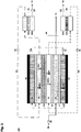
- the system of the present invention is defined in claim 1 and comprises at least one ion exchange unit 30.
- wastewater is provided through input 70, which is treated by the present system, and released from the system through output 71.
- a first alkaline recirculation unit comprising a gaseous ammonia stripper
- a second acidic recirculation unit comprising a gaseous CO 2 stripper
- a third electrode rinse recirculation unit 74a,b adapted to receive input from a first electrode rinse compartment (21,22), and for providing output to a second electrode rinse compartment, and vice versa.
- At least one of the gaseous ammonia stripper and of the gaseous CO 2 stripper comprises a hydrophobic membrane (61a, 62a), a molecular sieve for ammonia or for CO 2 , respectively, a pervaporation membrane, or a combination thereof, and the system comprises a tube (72) for removing gaseous ammonia, and a tube (73) for removing gaseous CO 2 .
- a pump 81 respectively, is provided.
- these alkaline and acidic recirculation units are separate from one and another. In the alkaline recirculation unit NH 3 (ammonia) is stripped, whereas in de acidic recirculation unit CO 2 is stripped, both as gaseous species.
- Each ion exchange unit comprises at least three compartments separated by membranes.
- the membranes provide exchange of NH 4 + (ammonium) from the second to the first compartment over the cation exchange membrane 12, and of HCO 3 - from the second to the third compartment over the anion exchange membrane 13; hence the membranes may be referred to as ion exchange membranes, such as cation and anion exchange membranes.
- the present also comprises at least two electrode rinse compartment 21,22, and typically two electrode rinse compartments; the at least two electrode rinse compartment have an adjacent membrane, selected from bipolar membranes, cation exchange membranes, and anion exchange membranes, respectively, which may provide exchange of NH 4 + , H + , OH - , or HCO 3 - , to or from the electrode rinse compartment 21,22, respectively.
- the third recirculation unit replenishes the at least electrode rinse compartment.
- the first electrode rinse compartment 21 is in electrical contact with an anode 41 and the second electrode rinse compartment 22 may be in electrical contact with an cathode 42. To the anode/cathode an electrical current is provided. Water and electrons form H + and OH - .
- the bipolar membrane (11a,b) is typically facing the alkaline compartment 31 or electrode rinse compartment 22 with a positive side and mutatis mutandis is typically facing the acidic compartment 33 or electrode rinse compartment 21 with a negative side.
- the bipolar membranes can generate H + , at a negative side thereof, and OH - , at a positive side thereof.
- the present invention relates to a method of treating wastewater, comprising NH 4 + , and HCO 3 - , using the present system.
- the present invention relates in a first aspect to a system according to claim 1.
- the third recirculation unit 74a,b is adapted to receive input from the first electrode rinse compartment 21, and for providing output to the second electrode rinse compartment 22, and vice versa. Therewith the liquids in the compartments may be replenished.
- a salt level in the compartments 21,22 may be 0.1-2 mole/l, such as by providing Na 2 SO 4 , NaNO 3 , NH 4 NO 3 , or NH 4 HCO 3 .
- the first electrode rinse compartment 21 may comprise NH 4 + or H + , or wherein the second electrode rinse compartment 22 comprises OH - or HCO 3 - , or a combination thereof.
- the at least one recirculation unit may comprise a membrane 61a, 62a, which typically is hydrophobic, such as a macroporous hydrophobic membrane, a molecular sieve for ammonia or for CO 2 , respectively, a pervaporation membrane, a pump 82, or a combination thereof.
- a membrane 61a, 62a typically is hydrophobic, such as a macroporous hydrophobic membrane, a molecular sieve for ammonia or for CO 2 , respectively, a pervaporation membrane, a pump 82, or a combination thereof.
- At least one membrane 61a,62a in the stripper may be impermeable to liquids, such as water, and permeable to gases, such as CO 2 and NH 3 , respectively.
- the stripper 61,62 typically comprises a strip chamber 61b,62b, respectively.
- the (hydrophobic) membrane 61a, 62a may be macroporous, with an average pore size of 50-500 nm, or microporous, with an average pore size of 0.4-10 nm, preferably 0.5-1 nm (as determined by electron microscopy).
- the membrane 11a,11b,12,13,61,62 may have a size from 50 cm 2 to 10 4 cm 2 , such as 10 2 -10 3 cm 2 , and a thickness of 100-7000 ⁇ m, such as 200-900 ⁇ m, a compartment 31,32,33,21,22 may have a width of 0.1-50 mm, such as 1-30 mm, and a flow may be parallel to the membrane.
- a membrane may comprise a support.
- Membranes 12 may be polyvinyl chloride based, with sulphonic acid in Na+ ionic form
- membranes 13 may be polyester based, with ammonium in Cl - ionic form.
- the membrane 61a,62a may be selected from polymeric material, preferably thermoplastic polymers, such as poly propylene and poly vinylidene fluoride, inorganic material, such as silica, and reinforced silica, and combinations thereof.
- polymeric material preferably thermoplastic polymers, such as poly propylene and poly vinylidene fluoride
- inorganic material such as silica, and reinforced silica, and combinations thereof.
- the exchange unit 30 may comprise a stack of a cation exchange membrane 12, an alkaline compartment 31, a bipolar membrane 11a, an acidic compartment 33, an anion exchange membrane 13, and a wastewater compartment 32, and wherein the second electrode rinse compartment 22 is in fluidic contact with a further cation exchange membrane 12, and wherein the third recirculation unit 74a,b is adapted to receive input from a first electrode rinse compartment 21 to compartment 22, and adapted to provide output to compartment 22 (see fig. 1 , 2 ).
- a cathode 42 may be provided in contact with a compartment 22 and an anode 41 may be provided in contact with compartment 21.
- the exchange unit 30 may comprise a stack of an anion exchange membrane 13, an acidic compartment 33, a bipolar membrane 11a, an alkaline compartment 31, a cation exchange membrane 12, and a wastewater compartment 32, and wherein the second electrode rinse compartment 22 is in fluidic contact with a further anion exchange membrane 13, and wherein the third recirculation unit 74a,b is adapted to receive input from a first electrode rinse compartment 21 to compartment 22, and adapted to provide output to compartment 21.
- a cathode 42 may be provided in contact with a compartment 22 and an anode 41 may be provided in contact with compartment 21.
- the exchange unit 30 may comprise a stack of an bipolar membrane 11a, an alkaline compartment 31, a cation exchange membrane 12, a wastewater compartment 32, an anion exchange membrane 13, and an acidic compartment 33, and wherein the first electrode rinse compartment 21 is in fluidic contact with a further bipolar membrane 11b, and wherein the third recirculation unit 74a,b is adapted to receive input from a first electrode rinse compartment 21 to compartment 22, and adapted to provide output to compartment 21, and vice versa to compartment 22 (see fig. 3 ).
- a cathode 42 may be provided in contact with a compartment 22 and an anode 41 may be provided in contact with compartment 21.
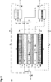
- the present system may comprise 2-2 10 ion exchange units 30 in parallel, preferably 4-2 9 ion exchange units, such as 200-400 ion exchange units.
- the system of the invention comprises a tube 72 for removing gaseous ammonia, and a tube 73 for removing gaseous CO 2 .
- At least one of a voltage of 0.1-5 V per ion exchange unit 30 may be applied, preferably 0.3- 3V, more preferably 0.5- 2V, such as 0.7-1.5V.
- a pH in the first alkaline compartment 31 may be from 7-14, preferably from 8-13, such as 9-12.
- a pH in the third acidic compartment 33 may be from 1-7, preferably 2-6.5, such as 2-6.
- a current density may be from 15-500 A/m 2 , such as 50-100 A/m 2 .
- a flow parallel to a membrane may each individually be from 0.01-0.20 m/s, such as 0.05-0.10 m/s.
- a NH 4 + flux over a membrane may each individually be 0.2-20 mole/m 2 /h, preferably 0.5-5 mole/m 2 /h, such as 1-2 mole/m 2 /h.
- a HCO 3 - flux over a membrane may each individually be 0.2-20 mole/m 2 /h, preferably 0.5-5 mole/m 2 /h, such as 1-2 mole/m 2 /h.
- an operating temperature may be from 10-80 °C.
- the [NH 4 + ] and [HCO 3 - ] in the second compartment 32 may each individually be 10 -3 -2 mole/l, preferably 10 -2 -1 mole/l, such as 10 -1 -0.5 mole/l.
- an NH 3 flux and a CO 2 flux in recirculation units 51,52 may each individually be 50-5000 g/m 2 /h, preferably 70-2500 g/m 2 /h, such as 100-1000 g/m 2 /h.
- membranes 11a,b,12 and 13 are separated by spacers 2 and the membranes 11a,b,12 and electrodes are also separated by spacers.
- transferring NH 4 + from the wastewater 70 to an alkaline recirculation solution 51 may be through a first compartment 31.
- transferring HCO 3 - from the wastewater to an acidic recirculation solution 52 may be through a third compartment 33.
- NH 4 + may be converted into NH 3 in the presence of OH - in the first compartment 31, and wherein HCO 3 - may be converted into CO 2 in the presence of H + in the third compartment 33.
- NH 3 may be stripped in ammonia stripper 61, and wherein CO 2 may be stripped in CO 2 stripper 62.
- an under pressure may be applied, such as of 0.1-90 kPa, preferably 1.5-75 kPa, such as 5-50 kPa.
- the present method may comprise forming NH 4 HCO 3 .
- wastewater may be provided by at least one of a domestic sewage treatment plant, a manure treatment facility, a fertilizer production plant, food and beverage industry, and an industry producing nitrogen loaded wastewater.
- an electrical potential difference over the cathode 42/anode 41 in electrodialysis with bipolar membranes 11a,11b is applied. Therewith decomposition of water is established.
- NH 4 HCO 3 is depleted in the wastewater, typically in a continuous or semi-continuous mode. However the present system may also be operated batch wise. Water is split over bipolar membranes 11a,11b thereby providing H + to the third compartment 33 and alkaline recycling compartment 21, respectively, and thereby providing OH - to the first compartment 31 and acidic recycling compartment 22, respectively.
- Fig. 1-5 show schematics of the present system.
- Fig. 1 shows a cell triplet provided with cation exchange membranes at the electrodes.
- Fig. 2 shows a cell triplet provided with anion exchange membranes at the electrodes.
- Fig. 3 shows a cell triplet provided with bipolar membranes at the electrodes.
- Fig. 4 represents a plural version of fig. 1 .
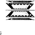
- Fig. 5 shows that all membranes (11,12 and 13) are separated by spacers 2.
- the spacers are made of polyethylene/silicone material and woven into a mesh.
- the liquids flow through the void fraction of the spacers, forming the salt, acid and alkaline chambers.
- the spacers are sealed on the top and bottom, making sure that the liquids are not leaking out of the membrane stack.
- the electrodes (anode and cathode) and the membranes next to the electrodes are also separated by spacers, forming the electrode rinse chambers.
Landscapes
- Chemical & Material Sciences (AREA)
- Water Supply & Treatment (AREA)
- Engineering & Computer Science (AREA)
- Chemical Kinetics & Catalysis (AREA)
- Life Sciences & Earth Sciences (AREA)
- Organic Chemistry (AREA)
- Hydrology & Water Resources (AREA)
- Environmental & Geological Engineering (AREA)
- Health & Medical Sciences (AREA)
- Analytical Chemistry (AREA)
- Molecular Biology (AREA)
- Electrochemistry (AREA)
- General Chemical & Material Sciences (AREA)
- Urology & Nephrology (AREA)
- Water Treatment By Electricity Or Magnetism (AREA)
- Separation Using Semi-Permeable Membranes (AREA)
Claims (15)
- Abwassergasrückgewinnungssystem (100) zum Zurückgewinnen von NH3 und CO2, das Folgendes umfasst:wenigstens eine Ionenaustauscheinheit (30), wobei jede Austauscheinheit wenigstens drei Ionenaustauschkammern (31, 32, 33) umfasst, wobei jede Ionenaustauschkammer über eine Membran mit wenigstens einer angrenzenden Kammer in Kontakt steht,eine erste alkalische Ionenaustauschkammer (31), die in Fluidkontakt mit einer positiven Seite der ersten bipolaren Membran (11a) und mit einer Kationenaustauschmembran (12) steht und wässriges NH4+ und OH- umfasst,eine zweite Ionenaustauschkammer (32), die in Fluidkontakt mit einer Anionenaustauschmembran (13) und mit einer Kationenaustauschmembran (12) steht und Wasser, NH4+ und HCO3- umfasst, undeine dritte saure Ionenaustauschkammer (33), die in Fluidkontakt mit einer negativen Seite einer bipolaren Membran (11a) und mit einer Anionenaustauschmembran (13) steht und wässriges H+ und HCO3- umfasst,eine Abwasserzufuhr (70) zum Bereitstellen von Abwasser an die zweite Kammer,eine Reinwasserausgabe (71), die angepasst ist, um eine Ausgabe von der zweiten Kammer zu empfangen,eine Kathode (42) und eine Anode (41) zum Bereitstellen einer Spannung, wobei wenigstens zwei Elektrodenspülkammern (21, 22) in elektrischem Kontakt mit der Kathode (42) oder mit der Anode (41) und mit einer Membran (11a, 11b, 12, 13) stehen und Salz umfassen,wenigstens drei Rezirkulationseinheiten (51, 52, 74a, 74b), einschließlich einer ersten alkalischen Rezirkulationseinheit (51), die angepasst ist, um eine Zufuhr von der ersten alkalischen Kammer (31) zu empfangen, umfassend eine Pumpe (81), einen Stripper (61) für gasförmiges Ammoniak, und zum Bereitstellen der gestrippten Ausgabe an die erste alkalische Kammer (31), eine zweite saure Rezirkulationseinheit (52), die angepasst ist, um die Zufuhr von der dritten sauren Kammer (33) zu empfangen, umfassend eine Pumpe (81), einen Stripper (62) für gasförmiges CO2, und zum Bereitstellen der gestripptem Ausgabe an die dritte saure Kammer (33), und eine dritte Rezirkulationseinheit (74a, 74b), die angepasst ist, um die Zufuhr von einem ersten Elektrodenspülfach (21) in elektrischem Kontakt mit der Anode (41) zu empfangen, und zum Bereitstellen der Ausgabe an eine zweite Elektrodenspülkammer (22) in elektrischem Kontakt mit der Kathode (42) und umgekehrt, wobei der Stripper (61) für gasförmiges Ammoniak und/oder der Stripper für gasförmiges CO2 eine hydrophobe Membran (61a, 62a), ein Molekularsieb für Ammoniak beziehungsweise für CO2, eine Pervaporationsmembran oder eine Kombination davon umfasst, undein Rohr (72) zum Entfernen von gasförmigem Ammoniak und ein Rohr (73) zum Entfernen von gasförmigem CO2.
- System nach Anspruch 1, wobei wenigstens eine Membran (61a, 62a) in dem Stripper für Flüssigkeiten undurchlässig und für Gase durchlässig ist.
- System nach einem der Ansprüche 1-2, wobei die hydrophobe Membran (61a, 62a) makroporös mit einer durchschnittlichen Porengröße von 50-500 nm oder mikroporös mit einer durchschnittlichen Porengröße von 0,4-10 nm ist (wie durch Elektronenmikroskopie bestimmt).
- System nach einem der Ansprüche 1-3, wobei die Membran (61a, 62a) aus Polymermaterial, anorganischem Material und Kombinationen davon ausgewählt ist.
- System nach einem der Ansprüche 1-4,
wobei die Austauscheinheit (30) einen Stapel einer Kationenaustauschmembran (12), einer alkalischen Ionenaustauschkammer (31), einer bipolaren Membran (11a), einer sauren Ionenaustauschkammer (33), einer Anionenaustauschmembran (13) und einer Abwasserionenaustauschkammer (32) umfasst, und wobei die zweite Elektrodenspülkammer (22) in Fluidkontakt mit einer weiteren Kationenaustauschmembran (12) steht, oder wobei die Austauscheinheit (30) einen Stapel einer Anionenaustauschmembran (13), einer sauren Ionenaustauschkammer (33), einer bipolaren Membran (11a), einer alkalischen Ionenaustauschkammer (31), einer Kationenaustauschmembran (12) und einer Abwasserionenaustauschkammer (32) umfasst, und wobei die erste Elektrodenspülkammer (21) in Fluidkontakt mit einer weiteren Anionenaustauschmembran (13) steht, oder wobei die Austauscheinheit (30) einen Stapel einer bipolaren Membran (11a), einer alkalischen Ionenaustauschkammer (31), einer Kationenaustauschmembran (12), einer Abwasserionenaustauschkammer (32), einer Anionenaustauschmembran (13) und einer sauren Ionenaustauschkammer (33) umfasst, und wobei die erste Elektrodenspülkammer (21) in Fluidkontakt mit einer weiteren bipolaren Membran (11b) steht. - System nach einem der Ansprüche 1-5, das 2 - 1024 Ionenaustauscheinheiten (30) parallel umfasst.
- System nach einem der Ansprüche 1-6, wobei die Membranen (11a, 11b, 12 und 13) durch Abstandshalter (2) getrennt sind und die Membranen (11a, 11b, 12) und Elektroden durch Abstandshalter (2) getrennt sind.
- System nach einem der Ansprüche 1-7, wobei in einem Betrieb wenigstens eine Spannung von 0,1-5 V pro Ionenaustauscheinheit (30) angelegt wird,ein pH-Wert in der ersten alkalischen Ionenaustauschkammer (31) von 7-14 beträgt,ein pH-Wert in der dritten sauren Ionenaustauschkammer (33) von 1-7 beträgt,eine Stromdichte von 5-500 A/m2 beträgt,ein Strom parallel zu einer Membran jeweils einzeln 0,01-0,20 m/s beträgt,ein NH4 +-Fluss über eine Membran jeweils einzeln 0,2-20 mol/m2/h beträgt,ein HCO3 --Fluss über eine Membran jeweils einzeln 0,2-20 mol/m2/h beträgt,eine Betriebstemperatur von 10-80 °C beträgt,das [NH4+] und [HCO3-] in der zweiten Ionenaustauschkammer (32) jeweils einzeln 10-3 ― 2 mol/l betragen,ein Vakuum von 0,1-90 kPa jeweils einzeln über Membranen (61, 62) angelegt wird,ein Fluss von Abwasser und Rezirkulation jeweils einzeln 0,01-10 kg/m2/h beträgt undein NH3-Fluss und ein CO2-Fluss in Rezirkulationseinheiten (51, 52) jeweils einzeln 50-5000 g/m2/h betragen.
- Verfahren zum Behandeln von Abwasser, das Folgendes umfasst:Bereitstellen eines Systems (100) nach einem der Ansprüche 1-8,Anlegen einer elektrischen Potentialdifferenz über die Anode (41)/Kathode (42),Bereitstellen von Abwasser in der zweiten Ionenaustauschkammer (32), die NH4+ und HCO3- umfasst,Übertragen von NH4+ aus dem Abwasser (70) an eine alkalische Rezirkulationslösung (51),gleichzeitig, Übertragen von HCO3- aus dem Abwasser an eine saure Rezirkulationslösung (52),Abreichern von NH4HCO3 in dem Abwasser, undAufspalten von Wasser über bipolare Membranen (11a, 11b), wobei dadurch H+ an die dritte saure Ionenaustauschkammer (33) bereitgestellt wird und wobei dadurch OH- an die erste alkalische Ionenaustauschkammer (31) bereitgestellt wird,wobei das Übertragen von NH4+ aus dem Abwasser (70) an eine alkalische Rezirkulationslösung (51) durch eine erste alkalische Ionenaustauschkammer (31) erfolgt,wobei das Übertragen von HCO3- aus dem Abwasser an eine saure Rezirkulationslösung (52) durch eine dritte saure Ionenaustauschkammer (33) erfolgt,wobei NH4+ in der Gegenwart von OH- in der ersten alkalischen Kammer (31) in NH3 umgewandelt wird und wobei HCO3- in der Gegenwart von H+ in der dritten sauren Ionenaustauschkammer (33) in CO2 umgewandelt wird,wobei NH3 in einem Ammoniak-Stripper (61) gestrippt wird und wobei CO2 in einem CO2-Stripper (62) gestrippt wird.
- Verfahren nach einem der Ansprüche 9, wobei an einer Gasseite des Strippers (61, 62) Unterdruck angelegt wird.
- Verfahren nach einem der Ansprüche 9-10, das ferner ein Ausbilden von NH4HCO3 umfasst.
- Verfahren nach einem der Ansprüche 9-11, wobei das Abwasser durch eine Haushaltskläranlage, eine Dungbehandlungseinrichtung, eine Düngemittelproduktionsanlage, eine Lebensmittel- und Getränkeindustrie und/oder eine Industrie bereitgestellt wird, die stickstoffbelastetes Abwasser produziert.
- Verfahren nach Anspruch 12, wobei Abwasser durch eine Dungbehandlungseinrichtung bereitgestellt wird.
- Verfahren nach einem der Ansprüche 9-13, wobei das NH3, wie in dem Ammoniak-Stripper (61) gestrippt, als Brennstoff für eine Festoxid-Brennstoffzelle verwendet wird, um elektrische Energie zurückzugewinnen.
- Verfahren nach Anspruch 14, wobei die zurückgewonnene Elektrizität in dem Verfahren zum Behandeln von Abwasser verwendet wird.
Priority Applications (1)
| Application Number | Priority Date | Filing Date | Title |
|---|---|---|---|
| PL19714855T PL3746407T3 (pl) | 2018-02-01 | 2019-01-31 | Odzyskiwanie gazu ze ścieków |
Applications Claiming Priority (3)
| Application Number | Priority Date | Filing Date | Title |
|---|---|---|---|
| NL2020369 | 2018-02-01 | ||
| NL2020528A NL2020528B1 (en) | 2018-03-05 | 2018-03-05 | Gas recovery from wastewater |
| PCT/NL2019/050058 WO2019151855A1 (en) | 2018-02-01 | 2019-01-31 | Gas recovery from wastewater |
Publications (2)
| Publication Number | Publication Date |
|---|---|
| EP3746407A1 EP3746407A1 (de) | 2020-12-09 |
| EP3746407B1 true EP3746407B1 (de) | 2021-12-15 |
Family
ID=65995823
Family Applications (1)
| Application Number | Title | Priority Date | Filing Date |
|---|---|---|---|
| EP19714855.4A Active EP3746407B1 (de) | 2018-02-01 | 2019-01-31 | Gasrückgewinnung aus abwasser |
Country Status (6)
| Country | Link |
|---|---|
| US (1) | US11554332B2 (de) |
| EP (1) | EP3746407B1 (de) |
| CA (1) | CA3090320A1 (de) |
| DK (1) | DK3746407T3 (de) |
| PL (1) | PL3746407T3 (de) |
| WO (1) | WO2019151855A1 (de) |
Families Citing this family (8)
| Publication number | Priority date | Publication date | Assignee | Title |
|---|---|---|---|---|
| WO2021144042A1 (en) * | 2020-01-15 | 2021-07-22 | Shell Internationale Research Maatschappij B.V. | Water treatment process |
| NL2032295B1 (en) | 2020-10-12 | 2023-12-15 | Mezt B V | Process to seperate an aqueous feed |
| NL2029462B1 (en) | 2020-10-19 | 2022-06-08 | Lenntech B V | Process for acid washing of a gas comprising ammonia |
| AU2023203655B2 (en) * | 2022-06-14 | 2025-07-17 | Asahi Kasei Kabushiki Kaisha | Method and system for ammonia recovery |
| US20240024823A1 (en) * | 2022-06-28 | 2024-01-25 | California Institute Of Technology | Systems and Methods for Bipolar Membranes |
| CN115259331B (zh) * | 2022-08-26 | 2023-09-08 | 中国科学院生态环境研究中心 | 用于废水脱氨的膜接触反应器及处理系统 |
| CN116514234B (zh) * | 2023-06-28 | 2023-09-01 | 广东工业大学 | 一种加载脉冲电场的堆栈式电化学氨回收装置及方法 |
| CN119263485B (zh) * | 2024-11-18 | 2025-11-25 | 清华大学 | 工业废水处理装置及其用于工业废水处理的方法 |
Family Cites Families (2)
| Publication number | Priority date | Publication date | Assignee | Title |
|---|---|---|---|---|
| US4969983A (en) | 1988-07-11 | 1990-11-13 | Ionics, Incorporated | Apparatus and process for the removal of acidic and basic gases from fluid mixtures using bipolar membranes |
| WO2015066811A1 (en) * | 2013-11-07 | 2015-05-14 | Saltworks Technologies Inc. | Removal of ammonia from ammonia-containing water using an electrodialysis process |
-
2019
- 2019-01-31 EP EP19714855.4A patent/EP3746407B1/de active Active
- 2019-01-31 PL PL19714855T patent/PL3746407T3/pl unknown
- 2019-01-31 CA CA3090320A patent/CA3090320A1/en active Pending
- 2019-01-31 WO PCT/NL2019/050058 patent/WO2019151855A1/en not_active Ceased
- 2019-01-31 DK DK19714855.4T patent/DK3746407T3/da active
- 2019-01-31 US US16/966,193 patent/US11554332B2/en active Active
Also Published As
| Publication number | Publication date |
|---|---|
| CA3090320A1 (en) | 2019-08-08 |
| WO2019151855A1 (en) | 2019-08-08 |
| US11554332B2 (en) | 2023-01-17 |
| PL3746407T3 (pl) | 2022-04-19 |
| EP3746407A1 (de) | 2020-12-09 |
| US20210138364A1 (en) | 2021-05-13 |
| DK3746407T3 (da) | 2022-03-21 |
Similar Documents
| Publication | Publication Date | Title |
|---|---|---|
| EP3746407B1 (de) | Gasrückgewinnung aus abwasser | |
| Xu et al. | Electrodialysis‐based separation technologies: a critical review | |
| CA2893708C (en) | Removal of ammonia from ammonia-containing water using an electrodialysis process | |
| US6224731B1 (en) | Apparatus and process for electrodialysis of salts | |
| US6627061B2 (en) | Apparatus and process for electrodialysis of salts | |
| Xu | Development of bipolar membrane-based processes | |
| US10508049B2 (en) | System for regenerating sodium hydroxide and sulfuric acid from waste water stream containing sodium and sulfate ions | |
| CN107098530A (zh) | 一种氯碱废水正渗透处理系统及处理工艺 | |
| CN102372398A (zh) | 一种同步产电和回收氮素的含氮污水处理工艺及装置 | |
| CN103771642A (zh) | 稀土皂化硫酸铵废水资源化方法 | |
| WO2008048103A1 (en) | Simultaneous acid and base production from an aqueous stream | |
| CN105154908A (zh) | 双极膜法从溶液中回收氢氧化锂工艺 | |
| KR20230134972A (ko) | 고농도 암모니아 하ㆍ폐수의 암모니아 회수 시스템 | |
| CN104609588A (zh) | 膜耦合处理高盐高氨氮废水的方法 | |
| CN114849478A (zh) | 一种不对称双极膜电渗析装置和制备酸碱的方法 | |
| KR20180111229A (ko) | 저 에너지 비용의 염분차발전-담수화 하이브리드 시스템 | |
| CN116444087A (zh) | 一种电渗析-气态膜法氨氮工业废水处理方法 | |
| CN116730447B (zh) | 飞灰水洗液资源化利用的方法和设备 | |
| CN104591423A (zh) | 一种高盐高氨氮废水的处理方法 | |
| Yonar | Electrodialysis Bipolar Membrane Systems-A Short Communication | |
| NL2020528B1 (en) | Gas recovery from wastewater | |
| CN214422428U (zh) | 一种正渗透酸回收系统 | |
| CN115710067A (zh) | 一种火电厂循环水冷却排污资源化利用方法 | |
| Thampy et al. | Concentration of sodium sulfate from pickle liquor of tannery effluent by electrodialysis | |
| CN112456697A (zh) | 一种正渗透酸回收系统 |
Legal Events
| Date | Code | Title | Description |
|---|---|---|---|
| STAA | Information on the status of an ep patent application or granted ep patent |
Free format text: STATUS: UNKNOWN |
|
| STAA | Information on the status of an ep patent application or granted ep patent |
Free format text: STATUS: THE INTERNATIONAL PUBLICATION HAS BEEN MADE |
|
| PUAI | Public reference made under article 153(3) epc to a published international application that has entered the european phase |
Free format text: ORIGINAL CODE: 0009012 |
|
| STAA | Information on the status of an ep patent application or granted ep patent |
Free format text: STATUS: REQUEST FOR EXAMINATION WAS MADE |
|
| 17P | Request for examination filed |
Effective date: 20200817 |
|
| AK | Designated contracting states |
Kind code of ref document: A1 Designated state(s): AL AT BE BG CH CY CZ DE DK EE ES FI FR GB GR HR HU IE IS IT LI LT LU LV MC MK MT NL NO PL PT RO RS SE SI SK SM TR |
|
| AX | Request for extension of the european patent |
Extension state: BA ME |
|
| DAV | Request for validation of the european patent (deleted) | ||
| DAX | Request for extension of the european patent (deleted) | ||
| GRAP | Despatch of communication of intention to grant a patent |
Free format text: ORIGINAL CODE: EPIDOSNIGR1 |
|
| STAA | Information on the status of an ep patent application or granted ep patent |
Free format text: STATUS: GRANT OF PATENT IS INTENDED |
|
| INTG | Intention to grant announced |
Effective date: 20210729 |
|
| GRAS | Grant fee paid |
Free format text: ORIGINAL CODE: EPIDOSNIGR3 |
|
| GRAA | (expected) grant |
Free format text: ORIGINAL CODE: 0009210 |
|
| STAA | Information on the status of an ep patent application or granted ep patent |
Free format text: STATUS: THE PATENT HAS BEEN GRANTED |
|
| AK | Designated contracting states |
Kind code of ref document: B1 Designated state(s): AL AT BE BG CH CY CZ DE DK EE ES FI FR GB GR HR HU IE IS IT LI LT LU LV MC MK MT NL NO PL PT RO RS SE SI SK SM TR |
|
| REG | Reference to a national code |
Ref country code: GB Ref legal event code: FG4D Ref country code: CH Ref legal event code: EP |
|
| REG | Reference to a national code |
Ref country code: IE Ref legal event code: FG4D Ref country code: DE Ref legal event code: R096 Ref document number: 602019010111 Country of ref document: DE |
|
| REG | Reference to a national code |
Ref country code: AT Ref legal event code: REF Ref document number: 1455382 Country of ref document: AT Kind code of ref document: T Effective date: 20220115 |
|
| REG | Reference to a national code |
Ref country code: FI Ref legal event code: FGE |
|
| REG | Reference to a national code |
Ref country code: SE Ref legal event code: TRGR |
|
| REG | Reference to a national code |
Ref country code: NL Ref legal event code: FP |
|
| REG | Reference to a national code |
Ref country code: DK Ref legal event code: T3 Effective date: 20220314 |
|
| REG | Reference to a national code |
Ref country code: NO Ref legal event code: T2 Effective date: 20211215 |
|
| REG | Reference to a national code |
Ref country code: LT Ref legal event code: MG9D |
|
| PG25 | Lapsed in a contracting state [announced via postgrant information from national office to epo] |
Ref country code: RS Free format text: LAPSE BECAUSE OF FAILURE TO SUBMIT A TRANSLATION OF THE DESCRIPTION OR TO PAY THE FEE WITHIN THE PRESCRIBED TIME-LIMIT Effective date: 20211215 Ref country code: LT Free format text: LAPSE BECAUSE OF FAILURE TO SUBMIT A TRANSLATION OF THE DESCRIPTION OR TO PAY THE FEE WITHIN THE PRESCRIBED TIME-LIMIT Effective date: 20211215 Ref country code: BG Free format text: LAPSE BECAUSE OF FAILURE TO SUBMIT A TRANSLATION OF THE DESCRIPTION OR TO PAY THE FEE WITHIN THE PRESCRIBED TIME-LIMIT Effective date: 20220315 |
|
| REG | Reference to a national code |
Ref country code: AT Ref legal event code: MK05 Ref document number: 1455382 Country of ref document: AT Kind code of ref document: T Effective date: 20211215 |
|
| PG25 | Lapsed in a contracting state [announced via postgrant information from national office to epo] |
Ref country code: LV Free format text: LAPSE BECAUSE OF FAILURE TO SUBMIT A TRANSLATION OF THE DESCRIPTION OR TO PAY THE FEE WITHIN THE PRESCRIBED TIME-LIMIT Effective date: 20211215 Ref country code: HR Free format text: LAPSE BECAUSE OF FAILURE TO SUBMIT A TRANSLATION OF THE DESCRIPTION OR TO PAY THE FEE WITHIN THE PRESCRIBED TIME-LIMIT Effective date: 20211215 Ref country code: GR Free format text: LAPSE BECAUSE OF FAILURE TO SUBMIT A TRANSLATION OF THE DESCRIPTION OR TO PAY THE FEE WITHIN THE PRESCRIBED TIME-LIMIT Effective date: 20220316 |
|
| PG25 | Lapsed in a contracting state [announced via postgrant information from national office to epo] |
Ref country code: SM Free format text: LAPSE BECAUSE OF FAILURE TO SUBMIT A TRANSLATION OF THE DESCRIPTION OR TO PAY THE FEE WITHIN THE PRESCRIBED TIME-LIMIT Effective date: 20211215 Ref country code: SK Free format text: LAPSE BECAUSE OF FAILURE TO SUBMIT A TRANSLATION OF THE DESCRIPTION OR TO PAY THE FEE WITHIN THE PRESCRIBED TIME-LIMIT Effective date: 20211215 Ref country code: RO Free format text: LAPSE BECAUSE OF FAILURE TO SUBMIT A TRANSLATION OF THE DESCRIPTION OR TO PAY THE FEE WITHIN THE PRESCRIBED TIME-LIMIT Effective date: 20211215 Ref country code: PT Free format text: LAPSE BECAUSE OF FAILURE TO SUBMIT A TRANSLATION OF THE DESCRIPTION OR TO PAY THE FEE WITHIN THE PRESCRIBED TIME-LIMIT Effective date: 20220418 Ref country code: ES Free format text: LAPSE BECAUSE OF FAILURE TO SUBMIT A TRANSLATION OF THE DESCRIPTION OR TO PAY THE FEE WITHIN THE PRESCRIBED TIME-LIMIT Effective date: 20211215 Ref country code: EE Free format text: LAPSE BECAUSE OF FAILURE TO SUBMIT A TRANSLATION OF THE DESCRIPTION OR TO PAY THE FEE WITHIN THE PRESCRIBED TIME-LIMIT Effective date: 20211215 Ref country code: CZ Free format text: LAPSE BECAUSE OF FAILURE TO SUBMIT A TRANSLATION OF THE DESCRIPTION OR TO PAY THE FEE WITHIN THE PRESCRIBED TIME-LIMIT Effective date: 20211215 |
|
| PG25 | Lapsed in a contracting state [announced via postgrant information from national office to epo] |
Ref country code: AT Free format text: LAPSE BECAUSE OF FAILURE TO SUBMIT A TRANSLATION OF THE DESCRIPTION OR TO PAY THE FEE WITHIN THE PRESCRIBED TIME-LIMIT Effective date: 20211215 |
|
| REG | Reference to a national code |
Ref country code: CH Ref legal event code: PL |
|
| REG | Reference to a national code |
Ref country code: DE Ref legal event code: R097 Ref document number: 602019010111 Country of ref document: DE |
|
| PG25 | Lapsed in a contracting state [announced via postgrant information from national office to epo] |
Ref country code: MC Free format text: LAPSE BECAUSE OF FAILURE TO SUBMIT A TRANSLATION OF THE DESCRIPTION OR TO PAY THE FEE WITHIN THE PRESCRIBED TIME-LIMIT Effective date: 20211215 Ref country code: IS Free format text: LAPSE BECAUSE OF FAILURE TO SUBMIT A TRANSLATION OF THE DESCRIPTION OR TO PAY THE FEE WITHIN THE PRESCRIBED TIME-LIMIT Effective date: 20220415 |
|
| PLBE | No opposition filed within time limit |
Free format text: ORIGINAL CODE: 0009261 |
|
| STAA | Information on the status of an ep patent application or granted ep patent |
Free format text: STATUS: NO OPPOSITION FILED WITHIN TIME LIMIT |
|
| PG25 | Lapsed in a contracting state [announced via postgrant information from national office to epo] |
Ref country code: LU Free format text: LAPSE BECAUSE OF NON-PAYMENT OF DUE FEES Effective date: 20220131 Ref country code: AL Free format text: LAPSE BECAUSE OF FAILURE TO SUBMIT A TRANSLATION OF THE DESCRIPTION OR TO PAY THE FEE WITHIN THE PRESCRIBED TIME-LIMIT Effective date: 20211215 |
|
| 26N | No opposition filed |
Effective date: 20220916 |
|
| PG25 | Lapsed in a contracting state [announced via postgrant information from national office to epo] |
Ref country code: SI Free format text: LAPSE BECAUSE OF FAILURE TO SUBMIT A TRANSLATION OF THE DESCRIPTION OR TO PAY THE FEE WITHIN THE PRESCRIBED TIME-LIMIT Effective date: 20211215 |
|
| PG25 | Lapsed in a contracting state [announced via postgrant information from national office to epo] |
Ref country code: LI Free format text: LAPSE BECAUSE OF NON-PAYMENT OF DUE FEES Effective date: 20220131 Ref country code: CH Free format text: LAPSE BECAUSE OF NON-PAYMENT OF DUE FEES Effective date: 20220131 |
|
| P01 | Opt-out of the competence of the unified patent court (upc) registered |
Effective date: 20230421 |
|
| PG25 | Lapsed in a contracting state [announced via postgrant information from national office to epo] |
Ref country code: MK Free format text: LAPSE BECAUSE OF FAILURE TO SUBMIT A TRANSLATION OF THE DESCRIPTION OR TO PAY THE FEE WITHIN THE PRESCRIBED TIME-LIMIT Effective date: 20211215 Ref country code: CY Free format text: LAPSE BECAUSE OF FAILURE TO SUBMIT A TRANSLATION OF THE DESCRIPTION OR TO PAY THE FEE WITHIN THE PRESCRIBED TIME-LIMIT Effective date: 20211215 |
|
| PG25 | Lapsed in a contracting state [announced via postgrant information from national office to epo] |
Ref country code: HU Free format text: LAPSE BECAUSE OF FAILURE TO SUBMIT A TRANSLATION OF THE DESCRIPTION OR TO PAY THE FEE WITHIN THE PRESCRIBED TIME-LIMIT; INVALID AB INITIO Effective date: 20190131 |
|
| PG25 | Lapsed in a contracting state [announced via postgrant information from national office to epo] |
Ref country code: MT Free format text: LAPSE BECAUSE OF FAILURE TO SUBMIT A TRANSLATION OF THE DESCRIPTION OR TO PAY THE FEE WITHIN THE PRESCRIBED TIME-LIMIT Effective date: 20211215 |
|
| PGFP | Annual fee paid to national office [announced via postgrant information from national office to epo] |
Ref country code: PL Payment date: 20250124 Year of fee payment: 7 |
|
| PG25 | Lapsed in a contracting state [announced via postgrant information from national office to epo] |
Ref country code: TR Free format text: LAPSE BECAUSE OF FAILURE TO SUBMIT A TRANSLATION OF THE DESCRIPTION OR TO PAY THE FEE WITHIN THE PRESCRIBED TIME-LIMIT Effective date: 20211215 |
|
| PGFP | Annual fee paid to national office [announced via postgrant information from national office to epo] |
Ref country code: NL Payment date: 20260122 Year of fee payment: 8 |
|
| PGFP | Annual fee paid to national office [announced via postgrant information from national office to epo] |
Ref country code: SE Payment date: 20260126 Year of fee payment: 8 |
|
| PGFP | Annual fee paid to national office [announced via postgrant information from national office to epo] |
Ref country code: GB Payment date: 20260126 Year of fee payment: 8 |
|
| PGFP | Annual fee paid to national office [announced via postgrant information from national office to epo] |
Ref country code: DE Payment date: 20260127 Year of fee payment: 8 Ref country code: NO Payment date: 20260120 Year of fee payment: 8 Ref country code: DK Payment date: 20260123 Year of fee payment: 8 Ref country code: IE Payment date: 20260120 Year of fee payment: 8 |
|
| PGFP | Annual fee paid to national office [announced via postgrant information from national office to epo] |
Ref country code: FI Payment date: 20260122 Year of fee payment: 8 Ref country code: BE Payment date: 20260123 Year of fee payment: 8 Ref country code: IT Payment date: 20260123 Year of fee payment: 8 |
|
| PGFP | Annual fee paid to national office [announced via postgrant information from national office to epo] |
Ref country code: FR Payment date: 20260126 Year of fee payment: 8 |