EP3746374B1 - Schneidwerkzeugverpackungsanordnung - Google Patents
Schneidwerkzeugverpackungsanordnung Download PDFInfo
- Publication number
- EP3746374B1 EP3746374B1 EP18778834.4A EP18778834A EP3746374B1 EP 3746374 B1 EP3746374 B1 EP 3746374B1 EP 18778834 A EP18778834 A EP 18778834A EP 3746374 B1 EP3746374 B1 EP 3746374B1
- Authority
- EP
- European Patent Office
- Prior art keywords
- packaging assembly
- cutting tool
- base plate
- cover member
- cutting
- Prior art date
- Legal status (The legal status is an assumption and is not a legal conclusion. Google has not performed a legal analysis and makes no representation as to the accuracy of the status listed.)
- Active
Links
Images


Classifications
-
- B—PERFORMING OPERATIONS; TRANSPORTING
- B65—CONVEYING; PACKING; STORING; HANDLING THIN OR FILAMENTARY MATERIAL
- B65D—CONTAINERS FOR STORAGE OR TRANSPORT OF ARTICLES OR MATERIALS, e.g. BAGS, BARRELS, BOTTLES, BOXES, CANS, CARTONS, CRATES, DRUMS, JARS, TANKS, HOPPERS, FORWARDING CONTAINERS; ACCESSORIES, CLOSURES, OR FITTINGS THEREFOR; PACKAGING ELEMENTS; PACKAGES
- B65D73/00—Packages comprising articles attached to cards, sheets or webs
- B65D73/0064—Packages comprising articles attached to cards, sheets or webs the articles being supported by or suspended from a tag-like element
-
- B—PERFORMING OPERATIONS; TRANSPORTING
- B65—CONVEYING; PACKING; STORING; HANDLING THIN OR FILAMENTARY MATERIAL
- B65D—CONTAINERS FOR STORAGE OR TRANSPORT OF ARTICLES OR MATERIALS, e.g. BAGS, BARRELS, BOTTLES, BOXES, CANS, CARTONS, CRATES, DRUMS, JARS, TANKS, HOPPERS, FORWARDING CONTAINERS; ACCESSORIES, CLOSURES, OR FITTINGS THEREFOR; PACKAGING ELEMENTS; PACKAGES
- B65D73/00—Packages comprising articles attached to cards, sheets or webs
- B65D73/0007—Packages comprising articles attached to cards, sheets or webs the articles being attached to the plane surface of a single card
- B65D73/0014—Packages comprising articles attached to cards, sheets or webs the articles being attached to the plane surface of a single card by means of separate fixing elements, e.g. clips, clamps, bands
Definitions
- the present disclosure relates to cutting tools. More specifically, the present disclosure relates to a packaging assembly which allows better sselling and safekeeping of the cutting tools.
- Cutting tools particularly small cutting tools, are generally packaged with a packaging which usually includes a vertical hanging arrangement. This allows a potential buyer to better interact with different details and specifications of the cutting tools. Ability of the potential buyer to interact with the cutting tool generally depends upon the accessibility permitted by the packaging. However, there have been many limitations with use of the common packaging available for the cutting tools.
- Some packaging also allows the potential buyer to perform limited operations with the cutting tools without having to completely remove the packaging. But, this could pose certain security threats for the potential buyer and may also have a bearing on life of the packaging or the cutting tool. Further, there are constraints to better market the cutting tools, preferably with better utilization of the packaging of the cutting tools.
- the '761 reference provides a safety suspension element with a fold-up rear wall.
- the safety suspension element includes a main body from which a suspension plate extends upwardly, in which a perforation is provided for suspending the main body. Further, lower part of the main body has an enclosing insertion opening through which a tool element can be inserted.
- the lower half of the plate surface of the rear wall is formed as an outwardly foldable movable plate at both ends of underside of the movable plate respectively.
- the '761 reference comes short of providing adequate safety, and security features while ensuring functionality of the tool within the suspension element.
- An example of a packaging assembly permitting movement of the cutting tool between an open blade configuration and closed blade configuration while ensuring safety and protection for a user is provided by US4873551A , US4165805A , DE2444606A1 .
- the objective is at least partially achieved by a packaging assembly for a cutting tool.
- the cutting tool has a first lever defining a first cutting edge.
- the cutting tool has a second lever defining a second cutting edge.
- the packaging assembly includes a base plate to receive the cutting tool.
- the base plate defines a cavity such that a first pivot pin coupling the first lever and the second lever of the cutting tool is received inside the cavity.
- the packaging assembly includes a primary cover member coupled to the base plate to restrain the cutting tool over the base plate such that the cutting tool can move between an open blade configuration and a closed blade configuration.
- the packaging assembly comprises a pivotally hinged section to pivot between an open position and a closed position allowing the cutting tool to be inserted into the packaging assembly.
- the packaging assembly is characterized in that the packaging assembly further includes a blade cover member for being fixedly coupled to the first cutting edge of the cutting tool such that the blade cover member covers an open space between the first cutting edge and the second cutting edge in an open blade configuration of the cutting tool.
- the present disclosure provides a simple, convenient and user-friendly packaging assembly for the cutting tool. Coupled to the first cutting edge is not to be understood that the coupling consists of a fixation of the blade cover member to the first cutting edge, but merely describes a fixed relationship between the two, where both elements touch each other. Thus when the fist cutting edge moves in space the blade cover member moves in the same direction not losing the touch with the first cutting edge and in this sense being coupled to it.
- the blade cover member covers an open space between the first cutting edge and the second cutting edge in the open blade configuration of the cutting tool. This ensures improved safety and protection for a user engaging with the cutting tool in the open blade configuration. Even more important the blade cover prevents the fingers of a user to enter the open space between the two cutting blades and thus get hurt when opening the cutting tool.
- the blade cover member stays between the first cutting edge and the second cutting edge in the closed blade configuration of the cutting tool. Presence of the blade cover in the closed blade configuration protects the first cutting edge and the second cutting edge from outside agents such as dust, moisture and the like, and simultaneously allows clear visibility of the cutting edges of the cutting tool.
- the pivotally hinged section is a part of the base plate.
- the pivotally hinged section of the packaging assembly allows proper securement of the cutting tool as per the application requirements.
- the pivotally hinged section is the primary cover member. Presence of the pivotally hinged section is in accordance with ease of assembly or disassembly of the cutting tool while ensuring a compact profile of the packaging assembly.
- the blade cover member is coupled to the cutting tool through the first pivot pin. This provides safekeeping and a theft-proof operation of the blade cover member even for non-use cases of the cutting tool.
- the blade cover member is further coupled to the first lever of the cutting tool through a second pivot pin. Provision of multiple pivot pins may be in consideration with a requirement of desired mechanical advantage among other reasons. In another embodiment, in particular if there does not exist a second pivot pin, the blade cover member may be fixed or additionally coupled onto the first lever via a snap fitting or the like.
- a surface of the blade cover member defines a first opening to receive the first pivot pin, and a second opening to receive the second pivot pin.
- Optimum locking of the cutting tool with the packaging assembly shall be a priority as provided by first opening and the first pivot pin, and the second opening and the second pivot pin of the present disclosure.
- a surface of the base plate further defines an arcuate slot to allow movement of the first lever relative to the second lever.
- the arcuate slot constrains the movement of the first lever between the open blade configuration and the closed blade configuration.
- the blade cover comprises of a transparent material.
- Use of the transparent material for the blade cover member ensures clear visibility of the cutting edges of the cutting tool at all times. This allows a user to be aware of the sharp cutting edges and ensures safe handling of the cutting tool on display.
- a secondary cover member is pivotally coupled to the base plate, such that the secondary cover member is adapted to restrain the second lever of the cutting tool over the base plate.
- the secondary cover member provides additional restrain on the second lever for optimum securement to the base plate of the packaging assembly.
- the base plate has one or more markings on a surface of the base plate.
- the markings are indicative of a size of an object which may be received for cutting between the first cutting edge and the second cutting edge. This allows the user to have a better understanding of profile of the object (say a branch) to be cut by the cutting tool.
- the packaging assembly further includes a surface cover adapted to cover the base plate.
- the surface cover may have at least one information such as specifications of the cutting tool, potential application areas, brand information, brand logo etc. displayed on the surface cover.
- the base plate further defines a hole to enable hanging the packaging assembly on a display panel. This finds applications such as for marketing, storing of the cutting tool in the packaging assembly.
- the cutting tool is a lopper.
- the cutting tool can be any tool as used or known in the art such as pruner, shears, or any other such cutting tools.
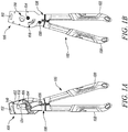
- FIGS. 1A and 1B illustrate front and back views respectively of a packaging assembly 100 as used for packaging a cutting tool 120.
- the present disclosure illustrates the cutting tool 120 as a pruner, however the packaging assembly 100 can be readily used with any other tool (such as shear, scissor, lopper or the like) or even fixture as known or used in the art.
- the present disclosure is not to be limited by the type of the cutting tool 120 in any manner.
- the packaging assembly 100 includes a base plate 102.
- the base plate 102 has a surface which defines a cavity 104.
- the packaging assembly 100 includes a primary cover member 106 coupled to the base plate 102.
- the primary cover member 104 is pivotally coupled to the base plate 102.
- the primary cover member 104 may pivot between an open position and a closed position.
- the primary cover member 104 restrains the cutting tool 120 over the base plate 102 such that the cutting tool 120 may move between an open blade configuration and a closed blade configuration.
- the packaging assembly 100 comprises a pivotally hinged section adapted to pivot between an open position and a closed position allowing the cutting tool 120 to be inserted into the packaging assembly 100.
- the pivotally hinged section 106 may be the primary cover member 106. This allows ease of placement or removal of the cutting tool 120 to/from the packaging assembly 100. Additionally, or alternatively, the pivotally hinged section 106 may be a part of the base plate 102. In such cases, the part of the base plate 102 will need to be hinged depending upon placement or removal of the cutting tool 120.
- the base plate 102 of the packaging assembly 100 further defines an arcuate slot 108.
- the cutting tool 120 may engage with the arcuate slot 108 to allow movement of a first lever 122 relative to a second lever 130.
- the base plate 102 of the packaging assembly 100 has one or more markings 110 on a surface of the base plate 102 indicative of a size of an object which may be received for cutting between the first cutting edge 124 and the second cutting edge 132.
- the markings 110 serve as a guide of the ability of the concerned cutting tool 120 to cut a range of objects such as branches.
- the markings 110 can directly correspond to the diameter of the objects to allow better comparison between different cutting tools 120 without having to remove the cutting tools 120 from their packaging assemblies.
- the packaging assembly 100 may have additional features which can contribute to increasing its appeal for application with different types of the cutting tools 120.
- the base plate 102 of the packaging assembly 100 further defines a hole 112 to enable hanging the packaging assembly 100 on a display panel (of a shop) or even in premises of the user. This enables the user to store the cutting tool 120 in the packaging assembly 100 especially for non-use periods of the cutting tool 120.
- the cutting tool 120 has the first lever 122 defining a first cutting edge 124, and the second lever 130 defining a second cutting edge 132.
- a secondary cover member 126 is pivotally coupled to the base plate 102, such that the secondary cover member 126 is adapted to restrain the second lever 130 of the cutting tool 120 over the base plate 102.
- the base plate 102 receives the cutting tool 120 such that a first pivot pin 134 coupling the first lever 122 and the second lever 130 of the cutting tool 120 is received inside the cavity 104. Further, the first pivot pin 134 can be supplemented by a second pivot pin 136 depending upon the type of the cutting tool 120. Moreover, the primary cover member 106 restrains the cutting tool 120 over the base plate 102 such that the cutting tool 120 can move between a closed blade configuration (shown in FIGS. 1A and 1B ) and an open blade configuration (shown in FIGS. 2A and 2B ).
- the packaging assembly 100 further includes a blade cover member 140 fixedly coupled to the first cutting edge 124 of the cutting tool 120 such that the blade cover member 140 covers a space between the first cutting edge 124 and the second cutting edge 132. As best illustrated in FIG. 1A , the blade cover member 140 stays between the first cutting edge 124 and the second cutting edge 132 in the closed blade configuration of the cutting tool 120. Further, since the blade cover member 140 is preferably made of a transparent or translucent material, depending upon the application requirements, a user can better appreciate the first cutting edge 124 or the second cutting edge 132 without a need of removing the blade cover member 140. This feature serves dual-purpose of protecting the user as well as the cutting tool 120 as will be appreciated by reference to various embodiments of the present disclosure.
- FIGS. 2A and 2B illustrate perspective views of the packaging assembly 100 with the cutting tool 120 in the open blade configuration, in accordance with an embodiment of the present invention.
- the blade cover member 140 covers an open space between the first cutting edge 124 and the second cutting edge 132 in the open blade configuration of the cutting tool 120. This ensures improved safety and protection for a user engaging with the open blade configuration. Moreover, protection by the blade cover member 140 ensures a longer and maintenance-free life at least till the time of first use of the cutting tool 120.
- the blade cover member 140 of the present disclosure can serve multiple purposes with or without the packaging assembly 100. Initially, the blade cover member 140 protects the first cutting edge 124 of the cutting tool 120 while the cutting tool 120 remains in the packaging assembly 100. Later, such as after-sale or first-use, the cutting tool 120 is taken out from the packaging assembly 100, however the blade cover member 140 may still be used without the packaging assembly 100 for a required time. This is allowed since the blade cover member 140 can be readily assembled or disassembled with the packaging assembly 100 as per the need.
- the blade cover member 140 is coupled to the cutting tool 120 through the first pivot pin 134.
- the blade cover member 140 is further coupled to the first lever 122 of the cutting tool 120 through the second pivot pin 136.
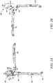
- FIGS. 3A and 3B illustrate perspective views of the packaging assembly 100, in accordance with an embodiment of the present invention.
- the packaging assembly 100 further includes a surface cover (not shown), which can be used to cover any face or side of the base plate 102.
- the surface cover may have at least one information such as, but not limited to, specifications, price, brand logo of the cutting tool 120 displayed on the surface cover.
- FIGS. 4A and 4B illustrate perspective views of the packaging assembly 100 without the cutting tool 120, in accordance with an embodiment of the present invention.
- surface of the blade cover member 140 defines a first opening 402 to receive the first pivot pin 134, and a second opening 404 to receive the second pivot pin 136.
- the blade cover member 140 can have only one opening to receive the first pivot pin 134.
- preference for a single or multiple opening such as the first opening 402 and the second opening 404 will usually depend upon factors such as relating to the cutting tool 120.
Landscapes
- Engineering & Computer Science (AREA)
- Mechanical Engineering (AREA)
- Knives (AREA)
- Packaging Of Annular Or Rod-Shaped Articles, Wearing Apparel, Cassettes, Or The Like (AREA)
Claims (13)
- Verpackungsanordnung (100) für ein Schneidwerkzeug (120), wobei das Schneidwerkzeug (120) einen ersten Hebel (122), der eine erste Schneidkante (124) definiert, und einen zweiten Hebel (130), der eine zweite Schneidkante (132) definiert, aufweist, wobei die Verpackungsanordnung (100) umfasst:eine Grundplatte (102), die geeignet ist, das Schneidwerkzeug (120) aufzunehmen, wobei die Grundplatte (102) einen Hohlraum (104) definiert, so dass ein erster Drehzapfens (134), der den ersten Hebel (122) und den zweiten Hebel (130) des Schneidwerkzeugs (120) koppelt, innerhalb des Hohlraums (104) aufgenommen wird;ein primäres Abdeckelement (106), das mit der Grundplatte (102) gekoppelt ist, das geeignet ist, das Schneidwerkzeug (120) über der Grundplatte (102) zurückzuhalten, so dass sich das Schneidwerkzeug (120) zwischen einer offenen Klingenkonfiguration und einer geschlossenen Klingenkonfiguration bewegen kann; undwobei die Verpackungsanordnung (100) einen schwenkbar angelenkten Abschnitt (106) umfasst, der angepasst ist, um zwischen einer offenen Position und einer geschlossenen Position zu schwenken, wodurch das Schneidwerkzeug (120) in die Verpackungsanordnung (100) eingeführt werden kann,dadurch gekennzeichnet, dass:
die Verpackungsanordnung (100) ferner ein Klingenabdeckungselement (140) umfasst, um fest mit der ersten Schneidkante (124) des Schneidwerkzeugs (120) gekoppelt zu werden, so dass das Klingenabdeckungselement (140) einen offenen Raum zwischen der ersten Schneidkante (124) und der zweiten Schneidkante (132) in einer offenen Klingenkonfiguration des Schneidwerkzeugs (120) abdeckt. - Verpackungsanordnung (100) nach einem der vorhergehenden Ansprüche, wobei der schwenkbar angelenkte Abschnitt (106) ein Teil der Grundplatte (102) ist.
- Verpackungsanordnung (100) nach einem der vorhergehenden Ansprüche, wobei der schwenkbar angelenkte Abschnitt (106) das primäre Abdeckelement (106) ist.
- Verpackungsanordnung (100) nach einem der vorhergehenden Ansprüche, wobei das Klingenabdeckungselement (140) mit dem Schneidwerkzeug (120) durch den ersten Drehzapfen (134) gekoppelt ist.
- Verpackungsanordnung (100) nach einem der vorhergehenden Ansprüche, wobei das Klingenabdeckungselement (140) ferner mit dem ersten Hebel (122) des Schneidwerkzeugs (120) durch einen zweiten Drehstift (136) gekoppelt ist.
- Verpackungsanordnung (100) nach Anspruch 5, wobei eine Oberfläche des Klingenabdeckungselements (140) eine erste Öffnung (402) zum Aufnehmen des ersten Drehzapfens (134) und eine zweite Öffnung (404) zum Aufnehmen des zweiten Drehzapfens (136) definiert.
- Verpackungsanordnung (100) nach einem der vorhergehenden Ansprüche, wobei eine Oberfläche der Grundplatte (102) ferner einen bogenförmigen Schlitz (108) definiert, um eine Bewegung des ersten Hebels (122) relativ zum zweiten Hebel (130) zu ermöglichen.
- Verpackungsanordnung (100) nach einem der vorhergehenden Ansprüche, wobei das Klingenabdeckungselement (140) aus einem transparenten Material besteht.
- Verpackungsanordnung (100) nach einem der vorhergehenden Ansprüche, wobei ein sekundäres Abdeckelement (126) schwenkbar mit der Grundplatte (102) derart gekoppelt ist, dass das sekundäre Abdeckelement (126) angepasst ist, um den zweiten Hebel (130) des Schneidwerkzeugs (120) über der Grundplatte (102) zu halten.
- Verpackungsanordnung (100) nach einem der vorhergehenden Ansprüche, wobei die Grundplatte (102) eine oder mehrere Markierungen (110) auf einer Oberfläche der Grundplatte (102) aufweist, die eine Größe eines zum Schneiden aufgenommenen Gegenstands zwischen der ersten Schneidkante (124) und der zweiten Schneidkante (132) anzeigen.
- Verpackungsanordnung (100) nach einem der vorhergehenden Ansprüche, die ferner eine Oberflächenabdeckung umfasst, die angepasst ist, um die Grundplatte (102) abzudecken, wobei die Oberflächenabdeckung mindestens eine auf der Oberflächenabdeckung angezeigte Information aufweist.
- Verpackungsanordnung (100) nach einem der vorhergehenden Ansprüche, wobei die Grundplatte (102) ferner ein Loch (112) definiert, um das Aufhängen der Verpackungsanordnung (100) an einer Anzeigetafel zu ermöglichen.
- Verpackungsanordnung (100) nach einem der vorhergehenden Ansprüche, wobei das Schneidwerkzeug (120) eine Astschere ist.
Priority Applications (1)
| Application Number | Priority Date | Filing Date | Title |
|---|---|---|---|
| PL18778834T PL3746374T3 (pl) | 2018-02-02 | 2018-09-14 | Zespół opakowaniowy narzędzia tnącego |
Applications Claiming Priority (2)
| Application Number | Priority Date | Filing Date | Title |
|---|---|---|---|
| DE102018000849 | 2018-02-02 | ||
| PCT/EP2018/074901 WO2019149392A1 (en) | 2018-02-02 | 2018-09-14 | Cutting tool packaging assembly |
Publications (2)
| Publication Number | Publication Date |
|---|---|
| EP3746374A1 EP3746374A1 (de) | 2020-12-09 |
| EP3746374B1 true EP3746374B1 (de) | 2022-01-05 |
Family
ID=63685943
Family Applications (1)
| Application Number | Title | Priority Date | Filing Date |
|---|---|---|---|
| EP18778834.4A Active EP3746374B1 (de) | 2018-02-02 | 2018-09-14 | Schneidwerkzeugverpackungsanordnung |
Country Status (3)
| Country | Link |
|---|---|
| EP (1) | EP3746374B1 (de) |
| PL (1) | PL3746374T3 (de) |
| WO (1) | WO2019149392A1 (de) |
Family Cites Families (4)
| Publication number | Priority date | Publication date | Assignee | Title |
|---|---|---|---|---|
| DE2444606A1 (de) * | 1974-09-18 | 1976-04-08 | Boos Fa Wilhelm Jun | Scheren-verkaufspackung |
| US4165805A (en) * | 1978-06-01 | 1979-08-28 | Fiskars Manufacturing Corporation | Blister packages for scissors, pliers and other hand tools |
| US4872551A (en) * | 1989-03-08 | 1989-10-10 | Klein Tools Corporation | Working clamshell blister package for pliers or similar hand tools |
| DE202012103761U1 (de) | 2012-04-23 | 2012-10-26 | Chun Nien Plastic Ltd. | Sicherheitsaufhängeelement mit hochklappbarer Rückwand |
-
2018
- 2018-09-14 EP EP18778834.4A patent/EP3746374B1/de active Active
- 2018-09-14 WO PCT/EP2018/074901 patent/WO2019149392A1/en not_active Ceased
- 2018-09-14 PL PL18778834T patent/PL3746374T3/pl unknown
Also Published As
| Publication number | Publication date |
|---|---|
| EP3746374A1 (de) | 2020-12-09 |
| PL3746374T3 (pl) | 2022-04-04 |
| WO2019149392A1 (en) | 2019-08-08 |
Similar Documents
| Publication | Publication Date | Title |
|---|---|---|
| EP1990292B1 (de) | Stützglied für ein mit einer schneide versehenes werkzeug | |
| CA2587288C (en) | Improved cutting tool | |
| US6131740A (en) | Toolbox | |
| US5291996A (en) | Reusable display sheath with frangible latch means | |
| ES2236596T3 (es) | Recipiente para cajetillas de cigarrillos o cigarros. | |
| USD873129S1 (en) | Container | |
| US20180117753A1 (en) | Multi-purpose tool | |
| US8534463B2 (en) | Electronic device accessory system | |
| USD554866S1 (en) | Haircutting case insert | |
| US6186323B1 (en) | Tool package | |
| EP3746374B1 (de) | Schneidwerkzeugverpackungsanordnung | |
| US7377043B2 (en) | Shearing apparatus | |
| US6854184B2 (en) | Blade cover for cutting device | |
| CA2645275A1 (en) | Container for holding an article | |
| US11213965B2 (en) | Axe cover with snapping mechanism | |
| JP4883575B2 (ja) | ドア | |
| EP3981705B1 (de) | Verpackung für ein schneidwerkzeug | |
| US20220314480A1 (en) | Multifunctional package opener having shrouded blades | |
| US4493148A (en) | Corrugated carton cutter | |
| EP4217291B1 (de) | Verpackung für ein schneidwerkzeug | |
| EP4169850A1 (de) | Verpackung für ein schneidwerkzeug | |
| CN106458405A (zh) | 用于锯片的悬挂标签包装件 | |
| US4300288A (en) | Can opener | |
| US20040040163A1 (en) | Protective cover for peeler | |
| JP6849240B2 (ja) | 情報端末機収納ケース |
Legal Events
| Date | Code | Title | Description |
|---|---|---|---|
| STAA | Information on the status of an ep patent application or granted ep patent |
Free format text: STATUS: UNKNOWN |
|
| STAA | Information on the status of an ep patent application or granted ep patent |
Free format text: STATUS: THE INTERNATIONAL PUBLICATION HAS BEEN MADE |
|
| PUAI | Public reference made under article 153(3) epc to a published international application that has entered the european phase |
Free format text: ORIGINAL CODE: 0009012 |
|
| STAA | Information on the status of an ep patent application or granted ep patent |
Free format text: STATUS: REQUEST FOR EXAMINATION WAS MADE |
|
| 17P | Request for examination filed |
Effective date: 20200512 |
|
| AK | Designated contracting states |
Kind code of ref document: A1 Designated state(s): AL AT BE BG CH CY CZ DE DK EE ES FI FR GB GR HR HU IE IS IT LI LT LU LV MC MK MT NL NO PL PT RO RS SE SI SK SM TR |
|
| AX | Request for extension of the european patent |
Extension state: BA ME |
|
| DAV | Request for validation of the european patent (deleted) | ||
| DAX | Request for extension of the european patent (deleted) | ||
| GRAP | Despatch of communication of intention to grant a patent |
Free format text: ORIGINAL CODE: EPIDOSNIGR1 |
|
| STAA | Information on the status of an ep patent application or granted ep patent |
Free format text: STATUS: GRANT OF PATENT IS INTENDED |
|
| GRAS | Grant fee paid |
Free format text: ORIGINAL CODE: EPIDOSNIGR3 |
|
| INTG | Intention to grant announced |
Effective date: 20211102 |
|
| GRAA | (expected) grant |
Free format text: ORIGINAL CODE: 0009210 |
|
| STAA | Information on the status of an ep patent application or granted ep patent |
Free format text: STATUS: THE PATENT HAS BEEN GRANTED |
|
| AK | Designated contracting states |
Kind code of ref document: B1 Designated state(s): AL AT BE BG CH CY CZ DE DK EE ES FI FR GB GR HR HU IE IS IT LI LT LU LV MC MK MT NL NO PL PT RO RS SE SI SK SM TR |
|
| REG | Reference to a national code |
Ref country code: GB Ref legal event code: FG4D |
|
| REG | Reference to a national code |
Ref country code: CH Ref legal event code: EP |
|
| REG | Reference to a national code |
Ref country code: AT Ref legal event code: REF Ref document number: 1460350 Country of ref document: AT Kind code of ref document: T Effective date: 20220115 |
|
| REG | Reference to a national code |
Ref country code: DE Ref legal event code: R096 Ref document number: 602018029188 Country of ref document: DE |
|
| REG | Reference to a national code |
Ref country code: IE Ref legal event code: FG4D |
|
| REG | Reference to a national code |
Ref country code: FI Ref legal event code: FGE |
|
| REG | Reference to a national code |
Ref country code: LT Ref legal event code: MG9D |
|
| REG | Reference to a national code |
Ref country code: NL Ref legal event code: MP Effective date: 20220105 |
|
| REG | Reference to a national code |
Ref country code: AT Ref legal event code: MK05 Ref document number: 1460350 Country of ref document: AT Kind code of ref document: T Effective date: 20220105 |
|
| PG25 | Lapsed in a contracting state [announced via postgrant information from national office to epo] |
Ref country code: NL Free format text: LAPSE BECAUSE OF FAILURE TO SUBMIT A TRANSLATION OF THE DESCRIPTION OR TO PAY THE FEE WITHIN THE PRESCRIBED TIME-LIMIT Effective date: 20220105 |
|
| PG25 | Lapsed in a contracting state [announced via postgrant information from national office to epo] |
Ref country code: SE Free format text: LAPSE BECAUSE OF FAILURE TO SUBMIT A TRANSLATION OF THE DESCRIPTION OR TO PAY THE FEE WITHIN THE PRESCRIBED TIME-LIMIT Effective date: 20220105 Ref country code: RS Free format text: LAPSE BECAUSE OF FAILURE TO SUBMIT A TRANSLATION OF THE DESCRIPTION OR TO PAY THE FEE WITHIN THE PRESCRIBED TIME-LIMIT Effective date: 20220105 Ref country code: PT Free format text: LAPSE BECAUSE OF FAILURE TO SUBMIT A TRANSLATION OF THE DESCRIPTION OR TO PAY THE FEE WITHIN THE PRESCRIBED TIME-LIMIT Effective date: 20220505 Ref country code: NO Free format text: LAPSE BECAUSE OF FAILURE TO SUBMIT A TRANSLATION OF THE DESCRIPTION OR TO PAY THE FEE WITHIN THE PRESCRIBED TIME-LIMIT Effective date: 20220405 Ref country code: LT Free format text: LAPSE BECAUSE OF FAILURE TO SUBMIT A TRANSLATION OF THE DESCRIPTION OR TO PAY THE FEE WITHIN THE PRESCRIBED TIME-LIMIT Effective date: 20220105 Ref country code: HR Free format text: LAPSE BECAUSE OF FAILURE TO SUBMIT A TRANSLATION OF THE DESCRIPTION OR TO PAY THE FEE WITHIN THE PRESCRIBED TIME-LIMIT Effective date: 20220105 Ref country code: ES Free format text: LAPSE BECAUSE OF FAILURE TO SUBMIT A TRANSLATION OF THE DESCRIPTION OR TO PAY THE FEE WITHIN THE PRESCRIBED TIME-LIMIT Effective date: 20220105 Ref country code: BG Free format text: LAPSE BECAUSE OF FAILURE TO SUBMIT A TRANSLATION OF THE DESCRIPTION OR TO PAY THE FEE WITHIN THE PRESCRIBED TIME-LIMIT Effective date: 20220405 |
|
| PG25 | Lapsed in a contracting state [announced via postgrant information from national office to epo] |
Ref country code: LV Free format text: LAPSE BECAUSE OF FAILURE TO SUBMIT A TRANSLATION OF THE DESCRIPTION OR TO PAY THE FEE WITHIN THE PRESCRIBED TIME-LIMIT Effective date: 20220105 Ref country code: GR Free format text: LAPSE BECAUSE OF FAILURE TO SUBMIT A TRANSLATION OF THE DESCRIPTION OR TO PAY THE FEE WITHIN THE PRESCRIBED TIME-LIMIT Effective date: 20220406 Ref country code: AT Free format text: LAPSE BECAUSE OF FAILURE TO SUBMIT A TRANSLATION OF THE DESCRIPTION OR TO PAY THE FEE WITHIN THE PRESCRIBED TIME-LIMIT Effective date: 20220105 |
|
| PG25 | Lapsed in a contracting state [announced via postgrant information from national office to epo] |
Ref country code: IS Free format text: LAPSE BECAUSE OF FAILURE TO SUBMIT A TRANSLATION OF THE DESCRIPTION OR TO PAY THE FEE WITHIN THE PRESCRIBED TIME-LIMIT Effective date: 20220505 |
|
| REG | Reference to a national code |
Ref country code: DE Ref legal event code: R097 Ref document number: 602018029188 Country of ref document: DE |
|
| PG25 | Lapsed in a contracting state [announced via postgrant information from national office to epo] |
Ref country code: SM Free format text: LAPSE BECAUSE OF FAILURE TO SUBMIT A TRANSLATION OF THE DESCRIPTION OR TO PAY THE FEE WITHIN THE PRESCRIBED TIME-LIMIT Effective date: 20220105 Ref country code: SK Free format text: LAPSE BECAUSE OF FAILURE TO SUBMIT A TRANSLATION OF THE DESCRIPTION OR TO PAY THE FEE WITHIN THE PRESCRIBED TIME-LIMIT Effective date: 20220105 Ref country code: RO Free format text: LAPSE BECAUSE OF FAILURE TO SUBMIT A TRANSLATION OF THE DESCRIPTION OR TO PAY THE FEE WITHIN THE PRESCRIBED TIME-LIMIT Effective date: 20220105 Ref country code: EE Free format text: LAPSE BECAUSE OF FAILURE TO SUBMIT A TRANSLATION OF THE DESCRIPTION OR TO PAY THE FEE WITHIN THE PRESCRIBED TIME-LIMIT Effective date: 20220105 Ref country code: DK Free format text: LAPSE BECAUSE OF FAILURE TO SUBMIT A TRANSLATION OF THE DESCRIPTION OR TO PAY THE FEE WITHIN THE PRESCRIBED TIME-LIMIT Effective date: 20220105 Ref country code: CZ Free format text: LAPSE BECAUSE OF FAILURE TO SUBMIT A TRANSLATION OF THE DESCRIPTION OR TO PAY THE FEE WITHIN THE PRESCRIBED TIME-LIMIT Effective date: 20220105 |
|
| PGFP | Annual fee paid to national office [announced via postgrant information from national office to epo] |
Ref country code: GB Payment date: 20220808 Year of fee payment: 5 |
|
| PLBE | No opposition filed within time limit |
Free format text: ORIGINAL CODE: 0009261 |
|
| STAA | Information on the status of an ep patent application or granted ep patent |
Free format text: STATUS: NO OPPOSITION FILED WITHIN TIME LIMIT |
|
| PG25 | Lapsed in a contracting state [announced via postgrant information from national office to epo] |
Ref country code: AL Free format text: LAPSE BECAUSE OF FAILURE TO SUBMIT A TRANSLATION OF THE DESCRIPTION OR TO PAY THE FEE WITHIN THE PRESCRIBED TIME-LIMIT Effective date: 20220105 |
|
| 26N | No opposition filed |
Effective date: 20221006 |
|
| PG25 | Lapsed in a contracting state [announced via postgrant information from national office to epo] |
Ref country code: SI Free format text: LAPSE BECAUSE OF FAILURE TO SUBMIT A TRANSLATION OF THE DESCRIPTION OR TO PAY THE FEE WITHIN THE PRESCRIBED TIME-LIMIT Effective date: 20220105 |
|
| PG25 | Lapsed in a contracting state [announced via postgrant information from national office to epo] |
Ref country code: MC Free format text: LAPSE BECAUSE OF FAILURE TO SUBMIT A TRANSLATION OF THE DESCRIPTION OR TO PAY THE FEE WITHIN THE PRESCRIBED TIME-LIMIT Effective date: 20220105 |
|
| REG | Reference to a national code |
Ref country code: CH Ref legal event code: PL |
|
| REG | Reference to a national code |
Ref country code: BE Ref legal event code: MM Effective date: 20220930 |
|
| P01 | Opt-out of the competence of the unified patent court (upc) registered |
Effective date: 20230419 |
|
| PG25 | Lapsed in a contracting state [announced via postgrant information from national office to epo] |
Ref country code: LU Free format text: LAPSE BECAUSE OF NON-PAYMENT OF DUE FEES Effective date: 20220914 |
|
| PG25 | Lapsed in a contracting state [announced via postgrant information from national office to epo] |
Ref country code: LI Free format text: LAPSE BECAUSE OF NON-PAYMENT OF DUE FEES Effective date: 20220930 Ref country code: IT Free format text: LAPSE BECAUSE OF FAILURE TO SUBMIT A TRANSLATION OF THE DESCRIPTION OR TO PAY THE FEE WITHIN THE PRESCRIBED TIME-LIMIT Effective date: 20220105 Ref country code: IE Free format text: LAPSE BECAUSE OF NON-PAYMENT OF DUE FEES Effective date: 20220914 Ref country code: CH Free format text: LAPSE BECAUSE OF NON-PAYMENT OF DUE FEES Effective date: 20220930 |
|
| PG25 | Lapsed in a contracting state [announced via postgrant information from national office to epo] |
Ref country code: BE Free format text: LAPSE BECAUSE OF NON-PAYMENT OF DUE FEES Effective date: 20220930 |
|
| PG25 | Lapsed in a contracting state [announced via postgrant information from national office to epo] |
Ref country code: CY Free format text: LAPSE BECAUSE OF FAILURE TO SUBMIT A TRANSLATION OF THE DESCRIPTION OR TO PAY THE FEE WITHIN THE PRESCRIBED TIME-LIMIT Effective date: 20220105 |
|
| GBPC | Gb: european patent ceased through non-payment of renewal fee |
Effective date: 20230914 |
|
| PG25 | Lapsed in a contracting state [announced via postgrant information from national office to epo] |
Ref country code: MK Free format text: LAPSE BECAUSE OF FAILURE TO SUBMIT A TRANSLATION OF THE DESCRIPTION OR TO PAY THE FEE WITHIN THE PRESCRIBED TIME-LIMIT Effective date: 20220105 Ref country code: HU Free format text: LAPSE BECAUSE OF FAILURE TO SUBMIT A TRANSLATION OF THE DESCRIPTION OR TO PAY THE FEE WITHIN THE PRESCRIBED TIME-LIMIT; INVALID AB INITIO Effective date: 20180914 |
|
| PG25 | Lapsed in a contracting state [announced via postgrant information from national office to epo] |
Ref country code: TR Free format text: LAPSE BECAUSE OF FAILURE TO SUBMIT A TRANSLATION OF THE DESCRIPTION OR TO PAY THE FEE WITHIN THE PRESCRIBED TIME-LIMIT Effective date: 20220105 |
|
| PG25 | Lapsed in a contracting state [announced via postgrant information from national office to epo] |
Ref country code: GB Free format text: LAPSE BECAUSE OF NON-PAYMENT OF DUE FEES Effective date: 20230914 |
|
| PG25 | Lapsed in a contracting state [announced via postgrant information from national office to epo] |
Ref country code: GB Free format text: LAPSE BECAUSE OF NON-PAYMENT OF DUE FEES Effective date: 20230914 |
|
| PG25 | Lapsed in a contracting state [announced via postgrant information from national office to epo] |
Ref country code: MT Free format text: LAPSE BECAUSE OF FAILURE TO SUBMIT A TRANSLATION OF THE DESCRIPTION OR TO PAY THE FEE WITHIN THE PRESCRIBED TIME-LIMIT Effective date: 20220105 |
|
| PGFP | Annual fee paid to national office [announced via postgrant information from national office to epo] |
Ref country code: FI Payment date: 20250805 Year of fee payment: 8 |
|
| PGFP | Annual fee paid to national office [announced via postgrant information from national office to epo] |
Ref country code: DE Payment date: 20250806 Year of fee payment: 8 |
|
| PGFP | Annual fee paid to national office [announced via postgrant information from national office to epo] |
Ref country code: PL Payment date: 20250714 Year of fee payment: 8 |
|
| PGFP | Annual fee paid to national office [announced via postgrant information from national office to epo] |
Ref country code: FR Payment date: 20250807 Year of fee payment: 8 |