EP3746207B9 - Kanalinterne siebung mit einem trommelsieb - Google Patents
Kanalinterne siebung mit einem trommelsieb Download PDFInfo
- Publication number
- EP3746207B9 EP3746207B9 EP19747688.0A EP19747688A EP3746207B9 EP 3746207 B9 EP3746207 B9 EP 3746207B9 EP 19747688 A EP19747688 A EP 19747688A EP 3746207 B9 EP3746207 B9 EP 3746207B9
- Authority
- EP
- European Patent Office
- Prior art keywords
- drum
- channel
- drum screen
- screen
- water
- Prior art date
- Legal status (The legal status is an assumption and is not a legal conclusion. Google has not performed a legal analysis and makes no representation as to the accuracy of the status listed.)
- Active
Links
Images



Classifications
-
- B—PERFORMING OPERATIONS; TRANSPORTING
- B01—PHYSICAL OR CHEMICAL PROCESSES OR APPARATUS IN GENERAL
- B01D—SEPARATION
- B01D33/00—Filters with filtering elements which move during the filtering operation
- B01D33/06—Filters with filtering elements which move during the filtering operation with rotary cylindrical filtering surfaces, e.g. hollow drums
- B01D33/067—Construction of the filtering drums, e.g. mounting or sealing arrangements
-
- B—PERFORMING OPERATIONS; TRANSPORTING
- B01—PHYSICAL OR CHEMICAL PROCESSES OR APPARATUS IN GENERAL
- B01D—SEPARATION
- B01D33/00—Filters with filtering elements which move during the filtering operation
- B01D33/06—Filters with filtering elements which move during the filtering operation with rotary cylindrical filtering surfaces, e.g. hollow drums
- B01D33/073—Filters with filtering elements which move during the filtering operation with rotary cylindrical filtering surfaces, e.g. hollow drums arranged for inward flow filtration
- B01D33/09—Filters with filtering elements which move during the filtering operation with rotary cylindrical filtering surfaces, e.g. hollow drums arranged for inward flow filtration with surface cells independently connected to pressure distributors
-
- B—PERFORMING OPERATIONS; TRANSPORTING
- B01—PHYSICAL OR CHEMICAL PROCESSES OR APPARATUS IN GENERAL
- B01D—SEPARATION
- B01D33/00—Filters with filtering elements which move during the filtering operation
- B01D33/06—Filters with filtering elements which move during the filtering operation with rotary cylindrical filtering surfaces, e.g. hollow drums
- B01D33/11—Filters with filtering elements which move during the filtering operation with rotary cylindrical filtering surfaces, e.g. hollow drums arranged for outward flow filtration
-
- B—PERFORMING OPERATIONS; TRANSPORTING
- B01—PHYSICAL OR CHEMICAL PROCESSES OR APPARATUS IN GENERAL
- B01D—SEPARATION
- B01D33/00—Filters with filtering elements which move during the filtering operation
- B01D33/44—Regenerating the filter material in the filter
- B01D33/46—Regenerating the filter material in the filter by scrapers, brushes nozzles or the like acting on the cake-side of the filtering element
- B01D33/463—Regenerating the filter material in the filter by scrapers, brushes nozzles or the like acting on the cake-side of the filtering element nozzles
-
- B—PERFORMING OPERATIONS; TRANSPORTING
- B01—PHYSICAL OR CHEMICAL PROCESSES OR APPARATUS IN GENERAL
- B01D—SEPARATION
- B01D33/00—Filters with filtering elements which move during the filtering operation
- B01D33/44—Regenerating the filter material in the filter
- B01D33/46—Regenerating the filter material in the filter by scrapers, brushes nozzles or the like acting on the cake-side of the filtering element
- B01D33/466—Regenerating the filter material in the filter by scrapers, brushes nozzles or the like acting on the cake-side of the filtering element scrapers
-
- B—PERFORMING OPERATIONS; TRANSPORTING
- B01—PHYSICAL OR CHEMICAL PROCESSES OR APPARATUS IN GENERAL
- B01D—SEPARATION
- B01D33/00—Filters with filtering elements which move during the filtering operation
- B01D33/44—Regenerating the filter material in the filter
- B01D33/48—Regenerating the filter material in the filter by flushing, e.g. counter-current air-bumps
- B01D33/50—Regenerating the filter material in the filter by flushing, e.g. counter-current air-bumps with backwash arms, shoes or nozzles
-
- B—PERFORMING OPERATIONS; TRANSPORTING
- B07—SEPARATING SOLIDS FROM SOLIDS; SORTING
- B07B—SEPARATING SOLIDS FROM SOLIDS BY SIEVING, SCREENING, SIFTING OR BY USING GAS CURRENTS; SEPARATING BY OTHER DRY METHODS APPLICABLE TO BULK MATERIAL, e.g. LOOSE ARTICLES FIT TO BE HANDLED LIKE BULK MATERIAL
- B07B1/00—Sieving, screening, sifting, or sorting solid materials using networks, gratings, grids, or the like
- B07B1/18—Drum screens
- B07B1/22—Revolving drums
-
- E—FIXED CONSTRUCTIONS
- E03—WATER SUPPLY; SEWERAGE
- E03F—SEWERS; CESSPOOLS
- E03F5/00—Sewerage structures
- E03F5/14—Devices for separating liquid or solid substances from sewage, e.g. sand or sludge traps, rakes or grates
-
- B—PERFORMING OPERATIONS; TRANSPORTING
- B01—PHYSICAL OR CHEMICAL PROCESSES OR APPARATUS IN GENERAL
- B01D—SEPARATION
- B01D2201/00—Details relating to filtering apparatus
- B01D2201/34—Seals or gaskets for filtering elements
- B01D2201/342—Axial sealings
-
- B—PERFORMING OPERATIONS; TRANSPORTING
- B01—PHYSICAL OR CHEMICAL PROCESSES OR APPARATUS IN GENERAL
- B01D—SEPARATION
- B01D33/00—Filters with filtering elements which move during the filtering operation
- B01D33/70—Filters with filtering elements which move during the filtering operation having feed or discharge devices
- B01D33/76—Filters with filtering elements which move during the filtering operation having feed or discharge devices for discharging the filter cake, e.g. chutes
-
- C—CHEMISTRY; METALLURGY
- C02—TREATMENT OF WATER, WASTE WATER, SEWAGE, OR SLUDGE
- C02F—TREATMENT OF WATER, WASTE WATER, SEWAGE, OR SLUDGE
- C02F1/00—Treatment of water, waste water, or sewage
- C02F1/001—Processes for the treatment of water whereby the filtration technique is of importance
- C02F1/004—Processes for the treatment of water whereby the filtration technique is of importance using large scale industrial sized filters
-
- C—CHEMISTRY; METALLURGY
- C02—TREATMENT OF WATER, WASTE WATER, SEWAGE, OR SLUDGE
- C02F—TREATMENT OF WATER, WASTE WATER, SEWAGE, OR SLUDGE
- C02F2303/00—Specific treatment goals
- C02F2303/24—Separation of coarse particles, e.g. by using sieves or screens
Definitions
- This invention concerns screening of objects from a water flow using a drum screen, and more particularly is concerned with an efficient flow pattern and arrangement of components in a drum screen system.
- the invention applies to wastewater treatment plants and other situations as well.
- Drum screens in such applications are typically large, with diameters of 15 feet or 18 feet or even larger, such as 36 feet or greater.
- Large wastewater treatment plants e.g. handling 150 million gallons per day, have employed drum screens of 36 feet diameter or greater.
- drum screen systems require special water flow channels, wide enough to contain the diameter of the drum.
- the channels simply are not wide enough to accept drums of a large enough size to handle the flow.
- Patent No. 5,407,563 describes screening panel constructions for use in band screens and drum screens.
- Figure 3 of that patent shows a schematic indication of a double-entry drum screen, the drum being of T-frame construction.
- the subject matter of the patent is the particular screen panel construction, and little description is given for Figure 3 , but the drawing has some relevance to the present invention.
- the invention is a new and more efficient flow arrangement that allows a drum screen to be more easily retrofitted into existing channels and requires less space in new construction.
- the invention places a reduced width drum screen in an orientation such that the shaft of the drum is perpendicular to the flow of the water.
- the drum diameter is approximately twice the depth of the channel with the drum shaft attached at deck level.
- the width of the drum may be approximately half the width of the channel in which the drum is placed (or about 45% to 55% of the channel width).
- the water flow will travel down the channel toward the drum where a diverter plate or "S" plate will direct water around and into the drum from the side.
- the plate, or a channel barrier connected to the plate may also have a simple automatic bypass gate or bypass weir to let excess flow bypass the screen in case of screen blinding. This will keep the channel from overflowing.
- the invention employs a high pressure, multi-nozzle water spray system to remove the drum screenings into the removal trough.
- Drum screens of the invention are preferably less than ten feet in diameter, and may be five feet, six feet, eight feet, etc. Such a drum screen is applicable particularly to wastewater plants of smaller capacity, e.g. under 10 million gallons per day (mgd), more preferably about 4 to 6 mgd. However, the efficient arrangement of the drum screen in the channel can also apply to larger plants with larger-diameter drum screens.
- the invention enables a drum screen to be installed efficiently in a channel for new construction, and also for retrofitting an existing channel in the plant, where a screen is to be replaced.
- the installation requires no complex concrete geometry.
- the preferred small size of the drum screens allows them to be fully fabricated before shipping, rather than requiring assembly and welding in the field, which is typical of normal, much larger drum screens.
- the drum screens of the invention are simple, with only two moving parts, bearings and pinion gear.
- a drum installation of the invention can be placed in a pumped flow system as well as other gravity flow channels. No submerged maintenance is required.
- the drum screen can produce a capture ratio of over 90%.
- the installation may include an automatic bypass or overflow gate.
- the drum screen system of the invention is economical, simple in construction with few moving parts, adaptable to almost any existing channel, and can be an ideal screening solution for many applications requiring screening.
- FIG 1 a drum screen installation of the invention is shown at 10.
- the system is shown mounted on and elevated above a concrete floor 12, for connection to a flow of water, e.g. wastewater input to a treatment plant, from what would be the left end of the drawing in Figure 1 .
- a flow of water e.g. wastewater input to a treatment plant
- the drum screen is shown at 14, being a relatively small drum screen no greater than about ten feet in diameter. The diameter may be about six feet. Panels of the drum screen are shown at 16, and these can have opening size in the range of about 0.5 mm to 10 mm, with 0.5 mm to about 2 mm typically used in polishing steps.
- the drum is supported on a rotational shaft 18, which is supported on bearings 20, one at each side.
- the direction of revolution of the drum in this particular installation is in the clockwise direction as viewed in this drawing, i.e. as shown by the directional arrow 22.
- the bottom of the drum screen thus moves against the direction of general flow through the installation.
- an outflow fitting downstream of the drum screen is shown at 24, for connection to a pipe, and with an inlet fitting at the inlet end, not seen in Figure 1 .
- Influent flow is indicated at 26, into a channel 28 that feeds the water into the far side of the drum screen 14.
- water level entering the drum screen is just below the rotation shaft 18.
- the outlet 24 could be at a different position, such as in line with the drum screen, if desired.
- the inlet flow then could be in line with the drum screen but diverted left just upstream of the drum to facilitate drum entry.
- the single-entry drum screen has all structural drum support at the near side as viewed in Figure 1 , without spokes or other radial obstructions at the opposite side. This allows intrusion of a debris catcher or discharge hopper from the far side into the drum interior, not seen in Figure 1 .
- the hopper feeds the debris to a wash water trough 34 which carries the debris away.
- Spray equipment 40 drives debris off the drum and into the hopper.
- the drum 14 is a cup drum, with a series of lifting elevators (not shown in Figure 1 ) on the inner side of the screen to help move debris up toward the discharge hopper.
- the water and debris enter pushing generally in the direction of flow. Much of the debris is caught near the bottom, and the debris rotates in the clockwise direction as seen in Figure 1 , up to a position near the top where it is sprayed from outside the screen with pressurized wash water at 40, preferably with high-velocity nozzles, to release it into the debris hopper.
- FIG. 1 through 5 The arrangement according to the invention shown in Figures 1 through 5 provides a compact assembly especially since the drum screen 14 is essentially parallel to the water or wastewater flow, rotatable on an axis that is perpendicular to that flow.
- Prior drum screen installations have usually had the rotational axis parallel to flow, so that influent liquid travels axially into one side of the drum in a single-entry system.
- these drums are very large, thus requiring a custom-built system of liquid channels that will accommodate that large diameter.
- the drum screen preferably is ten feet or less in diameter, with a maximum width to diameter ratio usually about 5:8, more typically about 1:2.
- the total channel width can be quite narrow, requiring a parallel flow offset to the side of the drum screen's width, with flow then directed into an open side of the single-entry drum.
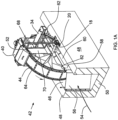
- Figures 1A through 5 show a single entry drum screen installation 42, with a drum screen 44 positioned in a channel 46, typically a concrete channel. This can be a retrofit in a channel which had been equipped with a different type of screening.
- the channel 46 is defined by concrete walls 48 and floor 50.
- the direction of rotation of the drum screen 44 is different from that of Figure 1 , with the drum screen's bottom moving in the general direction of water flow through the channel. This is preferable in a straight channel the debris being carried toward the outlet of the flow.
- the drum screen is positioned at one side of the channel, supported on a shaft 18 via bearings 20 as described above. The remaining channel width receives the full water flow.
- a debris hopper can be partially seen at 52, at or near the highest point of drum travel, and spray equipment is shown at 40, outside the drum and positioned to dislodge debris down into the hopper.
- a wash water trough is shown at 34, as above.
- a diverter plate 56 which can be referred to as an "S" plate due to its shape.
- this angled plate is connected to or integral with a seal plate 58 that seals against the side of the drum screen 44 as it rotates. The plate will also guide heavy debris into the drum from the channel floor.
- a large essentially semi-circular or open U-shaped opening 60 is defined by the seal plate 58 so that the water is diverted into the open side of the drum screen.
- a barrier is provided at 62, connected to or sealed against the seal plate 58 at right angles, to prevent water from bypassing the drum screen.
- Figures 2 to 5 show these features from different view points.
- the barrier 62 can act as a safety overflow weir.
- a drum drive gear is shown at 64.
- a motor and gearing in driving engagement with the drum gear 64 are shown at 66 in Figure 2 .
- Support structure is shown at 68 in Figures 1A , 2 and 3 , to support the debris trough 52, spray equipment 40, wash water trough 34 and water deflecting side plates 70 which can be on the concrete walls 48.
- the side plates 70 which can be hanging sheets of Neoprene, deflect and contain water from the spray nozzles.
- the flow of water through the installation is clearly depicted.
- the water enter alignment with the channel, as shown at the arrow 54, and is shifted to the right side of the channel 46 by the flow diverter plate 56.
- the water enters the side of the drum screen 44, thus being shifted back to the left side of the channel 46.
- the barrier 62 closes the right side of the channel at or near the downstream end of the drum screen as shown, being connected to the drum seal plate 58.
- the flow exiting the drum screen again fills the width of the channel 46 as indicated.
- Figures 4 and 5 show further details of the invention.
- the sectional view of Figure 4 is taken through the rotation shaft 18, looking toward the inlet end of the system.
- the debris hopper 52 is visible in Figure 4 , extending into the interior of the cup drum screen 44.
- the water deflecting side plates 70 are provided on each side, with the side plate on the left in Figure 4 open for movement of collected debris exiting from the hopper 52.
- Lift plates or elevators 72 are indicated on the interior of the drum screen, secured at spaced positions along the screen for moving debris up the drum to be collected in the hopper.
- Shown at the top of the drum screen in the position of Figure 4 is a flexible, preferably Neoprene wiper 73 that engages the hopper 52 once per revolution. The wiper 73 contacts the top edge of the hopper, deflects and wipes debris such as fabric items off the hopper lip.
- the spray equipment is shown at 40, above the hopper 52, with high pressure, high velocity nozzles to reliably dislodge debris off the screen and into the hopper.
- the high velocity, multi-nozzle spray can compensate for the relatively small diameter of the drum, which would otherwise make debris removal difficult.
- the nozzle pressure is about 45 to 90 psi, more preferably about 60 psi.
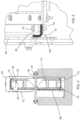
- FIG 4 shows a contact seal 74 secured to the rotating drum screen around a full circumference, deflected essentially 90° via pressure against the seal plate, to maintain a water seal. This is better seen in the enlarged detail of Figure 5 .
- the full-circumference seal 74 which can be of an elastomeric material such as Neoprene, is retained to the drum screen by fasteners such as bolts 76 passing through a plate 78 that extends around the circumference of the drum.
- the seal 74 which may be planar in its undeflected state, has a deflected arm 80 that bears against and slides along the seal plate 58 as shown. Since the seal 74 is allowed to partially return toward the undeflected state as it moves above the seal plate 58, the seal plate can have, as seen in Figure 1A , an angled guide 82 fixed to the seal plate to transition the seal back into its deflected position as it descends to again engage in a deflected configuration the seal plate. Note that in Figure 5 the sectioned portion of the seal plate 58 is at the bottom center of the drum, whereas above that sectioned region is the opening for flow into the drum. And thus, the edge of the seal plate 58 defining the opening is seen above the sectioned region.
Landscapes
- Chemical & Material Sciences (AREA)
- Chemical Kinetics & Catalysis (AREA)
- Health & Medical Sciences (AREA)
- Life Sciences & Earth Sciences (AREA)
- Engineering & Computer Science (AREA)
- Hydrology & Water Resources (AREA)
- Public Health (AREA)
- Water Supply & Treatment (AREA)
- Separation Of Solids By Using Liquids Or Pneumatic Power (AREA)
- Sewage (AREA)
Claims (10)
- Eine rotierende Trommelsieb-Kanalanlage (42), umfassend:einen Kanal, in dem Wasser fließt,eine Trommel (14) zum Aussieben von Abfall aus dem Wasserstrom im Kanal, wobei sich die Trommel um eine horizontale Achse (18) dreht, mit einer Welle, die die Trommel zur Drehung trägt, wobei die Welle auf einer festen Struktur des Kanals gelagert ist, und einem Sieb, das sich um den Umfang der Trommel erstreckt und das Trommelsieb (44) bildet,wobei die Achse des Trommelsiebs rechtwinklig zur Strömungsrichtung des Kanals angeordnet ist,dadurch gekennzeichnet, dassdie Trommel (14) eine Breite aufweist, die einen Teil einer Breite des Kanals (46) einnimmt, wobei eine verbleibende Breite des Kanals (46) für die Wasserströmung verbleibt, wobei das Trommelsieb (14) einen Durchmesser von nicht mehr als etwa 3 m (10 Fuß) aufweist und als Trommelsieb mit einem einzigen Einlass ausgebildet ist, wobei eine offene Seite (60) der verbleibenden Breite des Kanals (46) zugewandt ist und so angeordnet ist, dass sie eine Wasserströmung von der verbleibenden Breite des Kanals aufnimmt,wobei der Kanal (46) eine Strömungsrichtung von stromaufwärts nach stromabwärts aufweist und die verbleibende Breite des Kanals durch eine Barriere (62) nahe eines stromabwärts gelegenen Endes des Trommelsiebs blockiert ist, wobei die Barriere (62) so ausgebildet ist, dass sie den Kanal (46) zwischen einer Trommeldichtungsplatte (58) des Trommelsiebs (44) und einer Wand des Kanals schließt,wobei die Trommeldichtungsplatte (58) in dem Kanal (46) entlang der offenen Seite des Trommelsiebs angeordnet ist, mit einer flexiblen Kontaktdichtung (74) zwischen der Dichtungsplatte und einer kreisförmigen Seitenkante des drehbaren Trommelsiebs,wobei die Dichtungsplatte (58) eine Wassereinlassöffnung aufweist, um das Einströmen von Wasser in das Trommelsieb (14) von der offenen Seite her zu ermöglichen,eine Umlenkplatte (56) in dem Kanal vorgesehen ist, wobei ein stromabwärts gelegenes Ende der Umlenkplatte (56) mit einem stromaufwärts gelegenen Ende der Dichtungsplatte (58) verbunden ist, wobei die Umlenkplatte (56) ein stromaufwärts gelegenes Ende aufweist, das an einer Wand des Kanals (46) befestigt ist und an einem Boden des Kanals anliegt, wobei ein Hauptabschnitt der Umlenkplatte (56) so abgewinkelt ist, dass er einen parallelen Strömungsversatz bildet, um das durch den Kanal fließende Wasser und den Abfall in den Kanal mit der verbleibenden Breite zu leiten, bevor sie durch die Wassereinlassöffnung in das Trommelsieb eintreten, unddie Trommelsiebanlage einen Abfall-Sammelbehälter (52) innerhalb der Trommel aufweist, der in der Nähe eines höchsten Punktes der Trommel befestigt ist, um Abfall vom Sieb aufzufangen, während sich das Trommelsieb dreht, und mit einer Reihe von Hochdruckwasserdüsen (40) oberhalb der Trommel, die auf den Trichter gerichtet sind, um den Abfall vom Sieb in den Sammelbehälter zu verdrängen, und ferner einen Austrittstrog (34) aufweist, der so angeordnet ist, dass er den Abfall und das Wasser aus dem Sammelbehälter abführt.
- Rotierende Trommelsiebanlage nach Anspruch 1, wobei die Umlenkplatte (56) und die Dichtungsplatte (58) als eine Einzeleinheit ausgebildet sind.
- Rotierende Trommelsiebanlage nach Anspruch 2, bei der die Umlenkplatte (56) und die Dichtungsplatte (58) integral aus einem einzigen Stück geformt sind.
- Rotierende Trommelsiebanlage nach Anspruch 2, bei der die Umlenkplatte (56) und die Dichtungsplatte (58) am stromaufwärtigen Ende der Dichtungsplatte miteinander verbunden sind.
- Rotierende Trommelsiebanlage nach Anspruch 1, wobei die Wassereinlassöffnung eine Form hat, die allgemein der Form einer unteren Hälfte des Trommelsiebs (44) folgt, etwa als offener Halbkreis.
- Rotierende Trommelsiebanlage nach Anspruch 1, wobei die Hochdruckdüsen Wasser mit einem Mindestdruck von 3,1 bar (45 psi) versprühen.
- Rotierende Trommelsiebanlage nach Anspruch 1, bei der das Trommelsieb (44) etwa halb so breit ist wie der Kanal (46).
- Rotierende Trommelsiebanlage nach Anspruch 7, bei der das Trommelsieb (44) eine Breite von 45 % bis 55 % der Breite des Kanals (46) aufweist.
- Rotierende Trommelsiebanlage nach Anspruch 1, wobei die Kontaktdichtung (74) an der kreisförmigen Seitenkante des Trommelsiebs befestigt ist.
- Rotierende Trommelsiebanlage nach Anspruch 9, wobei die Kontaktdichtung (74) aus elastomerem Material besteht und durch Eingriff gegen die Dichtungsplatte in eine gebogene Ausgestaltung abgelenkt ist, um eine Dichtungskraft gegen die Dichtungsplatte auszuüben.
Applications Claiming Priority (2)
| Application Number | Priority Date | Filing Date | Title |
|---|---|---|---|
| US201862624069P | 2018-01-30 | 2018-01-30 | |
| PCT/US2019/015719 WO2019152435A1 (en) | 2018-01-30 | 2019-01-29 | In-channel screening with a drum screen |
Publications (4)
| Publication Number | Publication Date |
|---|---|
| EP3746207A1 EP3746207A1 (de) | 2020-12-09 |
| EP3746207A4 EP3746207A4 (de) | 2021-09-15 |
| EP3746207B1 EP3746207B1 (de) | 2023-04-26 |
| EP3746207B9 true EP3746207B9 (de) | 2023-07-05 |
Family
ID=66540940
Family Applications (1)
| Application Number | Title | Priority Date | Filing Date |
|---|---|---|---|
| EP19747688.0A Active EP3746207B9 (de) | 2018-01-30 | 2019-01-29 | Kanalinterne siebung mit einem trommelsieb |
Country Status (3)
| Country | Link |
|---|---|
| US (1) | US10293284B1 (de) |
| EP (1) | EP3746207B9 (de) |
| DK (1) | DK3746207T3 (de) |
Families Citing this family (3)
| Publication number | Priority date | Publication date | Assignee | Title |
|---|---|---|---|---|
| SE539965C2 (en) * | 2015-06-23 | 2018-02-13 | Veolia Water Solutions & Tech | Filter panel with a controlled liquid lift, and a drum filter for filtering liquid |
| NL2025346B1 (nl) * | 2020-04-15 | 2021-10-26 | Bimex B V | Trommelfilter voor het uit een vloeistof verwijderen van vaste delen, filtertrommel en flexibele afdichting voor toepassing in een dergelijke trommelfilter |
| CN114798411A (zh) * | 2022-03-28 | 2022-07-29 | 德州职业技术学院(德州市技师学院) | 一种电气控制的自动化智能筛选机 |
Family Cites Families (7)
| Publication number | Priority date | Publication date | Assignee | Title |
|---|---|---|---|---|
| GB556362A (en) * | 1942-03-16 | 1943-10-01 | Cyril John Hartley | Improvements in and relating to rotary screening apparatus |
| US4294700A (en) * | 1979-06-08 | 1981-10-13 | Envirex Inc. | Submerged large diameter seal |
| EP0026661B1 (de) * | 1979-09-27 | 1986-02-12 | Hawker Siddeley Brackett Limited | Apparat zum Behandeln einer Flüssigkeit, der mit einer rotierenden Trommel mit biegsamer Endabdichtung ausgerüstet ist |
| GB9006026D0 (en) * | 1990-03-16 | 1990-05-09 | Tomkinson & Co Ltd E | Screens |
| US5102536A (en) * | 1990-04-13 | 1992-04-07 | Wiesemann Engineering, Inc. | Self-cleaning water filter screen apparatus |
| US5407563A (en) * | 1990-05-24 | 1995-04-18 | Brackett Green Limited | Screening panels |
| DE4443091C1 (de) * | 1994-12-03 | 1996-01-25 | Metallgesellschaft Ag | Trommelsieb |
-
2019
- 2019-01-29 DK DK19747688.0T patent/DK3746207T3/da active
- 2019-01-29 EP EP19747688.0A patent/EP3746207B9/de active Active
- 2019-01-30 US US16/262,557 patent/US10293284B1/en active Active
Also Published As
| Publication number | Publication date |
|---|---|
| EP3746207B1 (de) | 2023-04-26 |
| DK3746207T3 (da) | 2023-07-31 |
| EP3746207A4 (de) | 2021-09-15 |
| EP3746207A1 (de) | 2020-12-09 |
| US10293284B1 (en) | 2019-05-21 |
Similar Documents
| Publication | Publication Date | Title |
|---|---|---|
| US10549224B2 (en) | Filter panel screen for a water intake including filter member with frusto-conical filter surface | |
| EP3746207B9 (de) | Kanalinterne siebung mit einem trommelsieb | |
| EP3519074B1 (de) | Rahmenartiger scheibenfilter mit bypasswasserkontrolle zur verhinderung der nutzung von bypasswasser in der rückspülung | |
| US10486091B2 (en) | Continuous belt screen | |
| EP1539323B1 (de) | Sedimentieranordnung | |
| US7267763B2 (en) | Water intake screen with circular filter panel | |
| GB2401328A (en) | Sewerage system screening arrangement | |
| US9206572B2 (en) | Traveling screen machine | |
| CA3095680C (en) | In-channel screening with a drum screen | |
| JP6984811B2 (ja) | 沈殿池設備 | |
| JP6833390B2 (ja) | 分散板ユニットおよび沈殿槽 | |
| US11713569B2 (en) | Stormwater treatment device | |
| US3349916A (en) | Self-cleaning rotary strainer | |
| US20230219021A1 (en) | Stormwater treatment device | |
| EP1206956A2 (de) | Rundbeckenräumer | |
| SU1744257A1 (ru) | Система управлени гидромонитором | |
| CN120398223A (zh) | 一种用于喷水织机的废水处理设备及其处理工艺 |
Legal Events
| Date | Code | Title | Description |
|---|---|---|---|
| STAA | Information on the status of an ep patent application or granted ep patent |
Free format text: STATUS: THE INTERNATIONAL PUBLICATION HAS BEEN MADE |
|
| PUAI | Public reference made under article 153(3) epc to a published international application that has entered the european phase |
Free format text: ORIGINAL CODE: 0009012 |
|
| STAA | Information on the status of an ep patent application or granted ep patent |
Free format text: STATUS: REQUEST FOR EXAMINATION WAS MADE |
|
| 17P | Request for examination filed |
Effective date: 20200825 |
|
| AK | Designated contracting states |
Kind code of ref document: A1 Designated state(s): AL AT BE BG CH CY CZ DE DK EE ES FI FR GB GR HR HU IE IS IT LI LT LU LV MC MK MT NL NO PL PT RO RS SE SI SK SM TR |
|
| AX | Request for extension of the european patent |
Extension state: BA ME |
|
| DAV | Request for validation of the european patent (deleted) | ||
| DAX | Request for extension of the european patent (deleted) | ||
| A4 | Supplementary search report drawn up and despatched |
Effective date: 20210818 |
|
| RIC1 | Information provided on ipc code assigned before grant |
Ipc: F16K 3/06 20060101ALI20210812BHEP Ipc: F03B 7/00 20060101ALI20210812BHEP Ipc: D21F 1/80 20060101ALI20210812BHEP Ipc: C02F 11/126 20190101ALI20210812BHEP Ipc: B07B 1/18 20060101ALI20210812BHEP Ipc: B01D 33/067 20060101ALI20210812BHEP Ipc: B01D 29/64 20060101AFI20210812BHEP |
|
| STAA | Information on the status of an ep patent application or granted ep patent |
Free format text: STATUS: EXAMINATION IS IN PROGRESS |
|
| 17Q | First examination report despatched |
Effective date: 20220510 |
|
| GRAP | Despatch of communication of intention to grant a patent |
Free format text: ORIGINAL CODE: EPIDOSNIGR1 |
|
| STAA | Information on the status of an ep patent application or granted ep patent |
Free format text: STATUS: GRANT OF PATENT IS INTENDED |
|
| INTG | Intention to grant announced |
Effective date: 20221118 |
|
| GRAS | Grant fee paid |
Free format text: ORIGINAL CODE: EPIDOSNIGR3 |
|
| GRAA | (expected) grant |
Free format text: ORIGINAL CODE: 0009210 |
|
| STAA | Information on the status of an ep patent application or granted ep patent |
Free format text: STATUS: THE PATENT HAS BEEN GRANTED |
|
| AK | Designated contracting states |
Kind code of ref document: B1 Designated state(s): AL AT BE BG CH CY CZ DE DK EE ES FI FR GB GR HR HU IE IS IT LI LT LU LV MC MK MT NL NO PL PT RO RS SE SI SK SM TR |
|
| REG | Reference to a national code |
Ref country code: GB Ref legal event code: FG4D |
|
| REG | Reference to a national code |
Ref country code: CH Ref legal event code: EP |
|
| REG | Reference to a national code |
Ref country code: DE Ref legal event code: R096 Ref document number: 602019028075 Country of ref document: DE |
|
| REG | Reference to a national code |
Ref country code: AT Ref legal event code: REF Ref document number: 1562418 Country of ref document: AT Kind code of ref document: T Effective date: 20230515 |
|
| REG | Reference to a national code |
Ref country code: IE Ref legal event code: FG4D |
|
| REG | Reference to a national code |
Ref country code: CH Ref legal event code: PK Free format text: BERICHTIGUNG B9 |
|
| REG | Reference to a national code |
Ref country code: DK Ref legal event code: T3 Effective date: 20230724 |
|
| REG | Reference to a national code |
Ref country code: NL Ref legal event code: FP |
|
| REG | Reference to a national code |
Ref country code: LT Ref legal event code: MG9D |
|
| REG | Reference to a national code |
Ref country code: AT Ref legal event code: MK05 Ref document number: 1562418 Country of ref document: AT Kind code of ref document: T Effective date: 20230426 |
|
| RAP2 | Party data changed (patent owner data changed or rights of a patent transferred) |
Owner name: OVIVO INC. |
|
| PG25 | Lapsed in a contracting state [announced via postgrant information from national office to epo] |
Ref country code: SE Free format text: LAPSE BECAUSE OF FAILURE TO SUBMIT A TRANSLATION OF THE DESCRIPTION OR TO PAY THE FEE WITHIN THE PRESCRIBED TIME-LIMIT Effective date: 20230426 Ref country code: PT Free format text: LAPSE BECAUSE OF FAILURE TO SUBMIT A TRANSLATION OF THE DESCRIPTION OR TO PAY THE FEE WITHIN THE PRESCRIBED TIME-LIMIT Effective date: 20230828 Ref country code: NO Free format text: LAPSE BECAUSE OF FAILURE TO SUBMIT A TRANSLATION OF THE DESCRIPTION OR TO PAY THE FEE WITHIN THE PRESCRIBED TIME-LIMIT Effective date: 20230726 Ref country code: ES Free format text: LAPSE BECAUSE OF FAILURE TO SUBMIT A TRANSLATION OF THE DESCRIPTION OR TO PAY THE FEE WITHIN THE PRESCRIBED TIME-LIMIT Effective date: 20230426 Ref country code: AT Free format text: LAPSE BECAUSE OF FAILURE TO SUBMIT A TRANSLATION OF THE DESCRIPTION OR TO PAY THE FEE WITHIN THE PRESCRIBED TIME-LIMIT Effective date: 20230426 |
|
| PG25 | Lapsed in a contracting state [announced via postgrant information from national office to epo] |
Ref country code: RS Free format text: LAPSE BECAUSE OF FAILURE TO SUBMIT A TRANSLATION OF THE DESCRIPTION OR TO PAY THE FEE WITHIN THE PRESCRIBED TIME-LIMIT Effective date: 20230426 Ref country code: PL Free format text: LAPSE BECAUSE OF FAILURE TO SUBMIT A TRANSLATION OF THE DESCRIPTION OR TO PAY THE FEE WITHIN THE PRESCRIBED TIME-LIMIT Effective date: 20230426 Ref country code: LV Free format text: LAPSE BECAUSE OF FAILURE TO SUBMIT A TRANSLATION OF THE DESCRIPTION OR TO PAY THE FEE WITHIN THE PRESCRIBED TIME-LIMIT Effective date: 20230426 Ref country code: LT Free format text: LAPSE BECAUSE OF FAILURE TO SUBMIT A TRANSLATION OF THE DESCRIPTION OR TO PAY THE FEE WITHIN THE PRESCRIBED TIME-LIMIT Effective date: 20230426 Ref country code: IS Free format text: LAPSE BECAUSE OF FAILURE TO SUBMIT A TRANSLATION OF THE DESCRIPTION OR TO PAY THE FEE WITHIN THE PRESCRIBED TIME-LIMIT Effective date: 20230826 Ref country code: HR Free format text: LAPSE BECAUSE OF FAILURE TO SUBMIT A TRANSLATION OF THE DESCRIPTION OR TO PAY THE FEE WITHIN THE PRESCRIBED TIME-LIMIT Effective date: 20230426 Ref country code: GR Free format text: LAPSE BECAUSE OF FAILURE TO SUBMIT A TRANSLATION OF THE DESCRIPTION OR TO PAY THE FEE WITHIN THE PRESCRIBED TIME-LIMIT Effective date: 20230727 |
|
| PG25 | Lapsed in a contracting state [announced via postgrant information from national office to epo] |
Ref country code: FI Free format text: LAPSE BECAUSE OF FAILURE TO SUBMIT A TRANSLATION OF THE DESCRIPTION OR TO PAY THE FEE WITHIN THE PRESCRIBED TIME-LIMIT Effective date: 20230426 |
|
| PG25 | Lapsed in a contracting state [announced via postgrant information from national office to epo] |
Ref country code: SK Free format text: LAPSE BECAUSE OF FAILURE TO SUBMIT A TRANSLATION OF THE DESCRIPTION OR TO PAY THE FEE WITHIN THE PRESCRIBED TIME-LIMIT Effective date: 20230426 |
|
| REG | Reference to a national code |
Ref country code: DE Ref legal event code: R097 Ref document number: 602019028075 Country of ref document: DE |
|
| PG25 | Lapsed in a contracting state [announced via postgrant information from national office to epo] |
Ref country code: SM Free format text: LAPSE BECAUSE OF FAILURE TO SUBMIT A TRANSLATION OF THE DESCRIPTION OR TO PAY THE FEE WITHIN THE PRESCRIBED TIME-LIMIT Effective date: 20230426 Ref country code: SK Free format text: LAPSE BECAUSE OF FAILURE TO SUBMIT A TRANSLATION OF THE DESCRIPTION OR TO PAY THE FEE WITHIN THE PRESCRIBED TIME-LIMIT Effective date: 20230426 Ref country code: RO Free format text: LAPSE BECAUSE OF FAILURE TO SUBMIT A TRANSLATION OF THE DESCRIPTION OR TO PAY THE FEE WITHIN THE PRESCRIBED TIME-LIMIT Effective date: 20230426 Ref country code: EE Free format text: LAPSE BECAUSE OF FAILURE TO SUBMIT A TRANSLATION OF THE DESCRIPTION OR TO PAY THE FEE WITHIN THE PRESCRIBED TIME-LIMIT Effective date: 20230426 Ref country code: CZ Free format text: LAPSE BECAUSE OF FAILURE TO SUBMIT A TRANSLATION OF THE DESCRIPTION OR TO PAY THE FEE WITHIN THE PRESCRIBED TIME-LIMIT Effective date: 20230426 |
|
| PLBE | No opposition filed within time limit |
Free format text: ORIGINAL CODE: 0009261 |
|
| STAA | Information on the status of an ep patent application or granted ep patent |
Free format text: STATUS: NO OPPOSITION FILED WITHIN TIME LIMIT |
|
| 26N | No opposition filed |
Effective date: 20240129 |
|
| PG25 | Lapsed in a contracting state [announced via postgrant information from national office to epo] |
Ref country code: SI Free format text: LAPSE BECAUSE OF FAILURE TO SUBMIT A TRANSLATION OF THE DESCRIPTION OR TO PAY THE FEE WITHIN THE PRESCRIBED TIME-LIMIT Effective date: 20230426 |
|
| PG25 | Lapsed in a contracting state [announced via postgrant information from national office to epo] |
Ref country code: SI Free format text: LAPSE BECAUSE OF FAILURE TO SUBMIT A TRANSLATION OF THE DESCRIPTION OR TO PAY THE FEE WITHIN THE PRESCRIBED TIME-LIMIT Effective date: 20230426 Ref country code: IT Free format text: LAPSE BECAUSE OF FAILURE TO SUBMIT A TRANSLATION OF THE DESCRIPTION OR TO PAY THE FEE WITHIN THE PRESCRIBED TIME-LIMIT Effective date: 20230426 |
|
| PG25 | Lapsed in a contracting state [announced via postgrant information from national office to epo] |
Ref country code: MC Free format text: LAPSE BECAUSE OF FAILURE TO SUBMIT A TRANSLATION OF THE DESCRIPTION OR TO PAY THE FEE WITHIN THE PRESCRIBED TIME-LIMIT Effective date: 20230426 |
|
| PG25 | Lapsed in a contracting state [announced via postgrant information from national office to epo] |
Ref country code: MC Free format text: LAPSE BECAUSE OF FAILURE TO SUBMIT A TRANSLATION OF THE DESCRIPTION OR TO PAY THE FEE WITHIN THE PRESCRIBED TIME-LIMIT Effective date: 20230426 |
|
| REG | Reference to a national code |
Ref country code: CH Ref legal event code: PL |
|
| PG25 | Lapsed in a contracting state [announced via postgrant information from national office to epo] |
Ref country code: LU Free format text: LAPSE BECAUSE OF NON-PAYMENT OF DUE FEES Effective date: 20240129 |
|
| PG25 | Lapsed in a contracting state [announced via postgrant information from national office to epo] |
Ref country code: LU Free format text: LAPSE BECAUSE OF NON-PAYMENT OF DUE FEES Effective date: 20240129 |
|
| PG25 | Lapsed in a contracting state [announced via postgrant information from national office to epo] |
Ref country code: BE Free format text: LAPSE BECAUSE OF NON-PAYMENT OF DUE FEES Effective date: 20240131 |
|
| PG25 | Lapsed in a contracting state [announced via postgrant information from national office to epo] |
Ref country code: CH Free format text: LAPSE BECAUSE OF NON-PAYMENT OF DUE FEES Effective date: 20240131 |
|
| PG25 | Lapsed in a contracting state [announced via postgrant information from national office to epo] |
Ref country code: CH Free format text: LAPSE BECAUSE OF NON-PAYMENT OF DUE FEES Effective date: 20240131 Ref country code: BE Free format text: LAPSE BECAUSE OF NON-PAYMENT OF DUE FEES Effective date: 20240131 |
|
| REG | Reference to a national code |
Ref country code: BE Ref legal event code: MM Effective date: 20240131 |
|
| PG25 | Lapsed in a contracting state [announced via postgrant information from national office to epo] |
Ref country code: BG Free format text: LAPSE BECAUSE OF FAILURE TO SUBMIT A TRANSLATION OF THE DESCRIPTION OR TO PAY THE FEE WITHIN THE PRESCRIBED TIME-LIMIT Effective date: 20230426 |
|
| PG25 | Lapsed in a contracting state [announced via postgrant information from national office to epo] |
Ref country code: BG Free format text: LAPSE BECAUSE OF FAILURE TO SUBMIT A TRANSLATION OF THE DESCRIPTION OR TO PAY THE FEE WITHIN THE PRESCRIBED TIME-LIMIT Effective date: 20230426 |
|
| PG25 | Lapsed in a contracting state [announced via postgrant information from national office to epo] |
Ref country code: IE Free format text: LAPSE BECAUSE OF NON-PAYMENT OF DUE FEES Effective date: 20240129 |
|
| PG25 | Lapsed in a contracting state [announced via postgrant information from national office to epo] |
Ref country code: IE Free format text: LAPSE BECAUSE OF NON-PAYMENT OF DUE FEES Effective date: 20240129 |
|
| REG | Reference to a national code |
Ref country code: DE Ref legal event code: R082 Ref document number: 602019028075 Country of ref document: DE Representative=s name: MEISSNER BOLTE PATENTANWAELTE RECHTSANWAELTE P, DE |
|
| PG25 | Lapsed in a contracting state [announced via postgrant information from national office to epo] |
Ref country code: CY Free format text: LAPSE BECAUSE OF FAILURE TO SUBMIT A TRANSLATION OF THE DESCRIPTION OR TO PAY THE FEE WITHIN THE PRESCRIBED TIME-LIMIT; INVALID AB INITIO Effective date: 20190129 |
|
| PG25 | Lapsed in a contracting state [announced via postgrant information from national office to epo] |
Ref country code: HU Free format text: LAPSE BECAUSE OF FAILURE TO SUBMIT A TRANSLATION OF THE DESCRIPTION OR TO PAY THE FEE WITHIN THE PRESCRIBED TIME-LIMIT; INVALID AB INITIO Effective date: 20190129 |
|
| PG25 | Lapsed in a contracting state [announced via postgrant information from national office to epo] |
Ref country code: TR Free format text: LAPSE BECAUSE OF FAILURE TO SUBMIT A TRANSLATION OF THE DESCRIPTION OR TO PAY THE FEE WITHIN THE PRESCRIBED TIME-LIMIT Effective date: 20230426 |
|
| PGFP | Annual fee paid to national office [announced via postgrant information from national office to epo] |
Ref country code: NL Payment date: 20260126 Year of fee payment: 8 |
|
| PGFP | Annual fee paid to national office [announced via postgrant information from national office to epo] |
Ref country code: GB Payment date: 20260127 Year of fee payment: 8 |
|
| PGFP | Annual fee paid to national office [announced via postgrant information from national office to epo] |
Ref country code: DE Payment date: 20260128 Year of fee payment: 8 Ref country code: DK Payment date: 20260126 Year of fee payment: 8 |
|
| REG | Reference to a national code |
Ref country code: DE Ref legal event code: R081 Ref document number: 602019028075 Country of ref document: DE Owner name: AVILES, ABNER, AMERICAN FORK, US Free format text: FORMER OWNERS: AVILES, ABNER, AMERICAN FORK, UT, US; HOLINDRAKE, JARED, SALT LAKE CITY, UT, US; KEEVER, CHRISTOPHER, PEACHTREE CITY, GA, US; OVIVO INC., MONTREAL, CA Ref country code: DE Ref legal event code: R081 Ref document number: 602019028075 Country of ref document: DE Owner name: HOLINDRAKE, JARED, SALT LAKE CITY, US Free format text: FORMER OWNERS: AVILES, ABNER, AMERICAN FORK, UT, US; HOLINDRAKE, JARED, SALT LAKE CITY, UT, US; KEEVER, CHRISTOPHER, PEACHTREE CITY, GA, US; OVIVO INC., MONTREAL, CA Ref country code: DE Ref legal event code: R081 Ref document number: 602019028075 Country of ref document: DE Owner name: KEEVER, CHRISTOPHER, PEACHTREE CITY, US Free format text: FORMER OWNERS: AVILES, ABNER, AMERICAN FORK, UT, US; HOLINDRAKE, JARED, SALT LAKE CITY, UT, US; KEEVER, CHRISTOPHER, PEACHTREE CITY, GA, US; OVIVO INC., MONTREAL, CA Ref country code: DE Ref legal event code: R081 Ref document number: 602019028075 Country of ref document: DE Owner name: OVIVO WATER INC., MONTREAL, CA Free format text: FORMER OWNERS: AVILES, ABNER, AMERICAN FORK, UT, US; HOLINDRAKE, JARED, SALT LAKE CITY, UT, US; KEEVER, CHRISTOPHER, PEACHTREE CITY, GA, US; OVIVO INC., MONTREAL, CA |
|
| PGFP | Annual fee paid to national office [announced via postgrant information from national office to epo] |
Ref country code: FR Payment date: 20260126 Year of fee payment: 8 |