EP3745735B1 - Kopfhörer der einen abgedichteten belüftungskanal mit einem ersten ohrstück und einen offenen belüftungskanal mit einem zweiten ohrstück definiert - Google Patents
Kopfhörer der einen abgedichteten belüftungskanal mit einem ersten ohrstück und einen offenen belüftungskanal mit einem zweiten ohrstück definiert Download PDFInfo
- Publication number
- EP3745735B1 EP3745735B1 EP20174549.4A EP20174549A EP3745735B1 EP 3745735 B1 EP3745735 B1 EP 3745735B1 EP 20174549 A EP20174549 A EP 20174549A EP 3745735 B1 EP3745735 B1 EP 3745735B1
- Authority
- EP
- European Patent Office
- Prior art keywords
- eartip
- earphone
- housing
- holding portion
- sound emitting
- Prior art date
- Legal status (The legal status is an assumption and is not a legal conclusion. Google has not performed a legal analysis and makes no representation as to the accuracy of the status listed.)
- Active
Links
Images


Classifications
-
- H—ELECTRICITY
- H04—ELECTRIC COMMUNICATION TECHNIQUE
- H04R—LOUDSPEAKERS, MICROPHONES, GRAMOPHONE PICK-UPS OR LIKE ACOUSTIC ELECTROMECHANICAL TRANSDUCERS; ELECTRIC HEARING AIDS; PUBLIC ADDRESS SYSTEMS
- H04R1/00—Details of transducers, loudspeakers or microphones
- H04R1/10—Earpieces; Attachments therefor ; Earphones; Monophonic headphones
- H04R1/1016—Earpieces of the intra-aural type
-
- H—ELECTRICITY
- H04—ELECTRIC COMMUNICATION TECHNIQUE
- H04R—LOUDSPEAKERS, MICROPHONES, GRAMOPHONE PICK-UPS OR LIKE ACOUSTIC ELECTROMECHANICAL TRANSDUCERS; ELECTRIC HEARING AIDS; PUBLIC ADDRESS SYSTEMS
- H04R1/00—Details of transducers, loudspeakers or microphones
- H04R1/10—Earpieces; Attachments therefor ; Earphones; Monophonic headphones
- H04R1/1058—Manufacture or assembly
- H04R1/1075—Mountings of transducers in earphones or headphones
-
- H—ELECTRICITY
- H04—ELECTRIC COMMUNICATION TECHNIQUE
- H04R—LOUDSPEAKERS, MICROPHONES, GRAMOPHONE PICK-UPS OR LIKE ACOUSTIC ELECTROMECHANICAL TRANSDUCERS; ELECTRIC HEARING AIDS; PUBLIC ADDRESS SYSTEMS
- H04R1/00—Details of transducers, loudspeakers or microphones
- H04R1/10—Earpieces; Attachments therefor ; Earphones; Monophonic headphones
- H04R1/1091—Details not provided for in groups H04R1/1008 - H04R1/1083
-
- H—ELECTRICITY
- H04—ELECTRIC COMMUNICATION TECHNIQUE
- H04R—LOUDSPEAKERS, MICROPHONES, GRAMOPHONE PICK-UPS OR LIKE ACOUSTIC ELECTROMECHANICAL TRANSDUCERS; ELECTRIC HEARING AIDS; PUBLIC ADDRESS SYSTEMS
- H04R1/00—Details of transducers, loudspeakers or microphones
- H04R1/20—Arrangements for obtaining desired frequency or directional characteristics
- H04R1/22—Arrangements for obtaining desired frequency or directional characteristics for obtaining desired frequency characteristic only
- H04R1/28—Transducer mountings or enclosures modified by provision of mechanical or acoustic impedances, e.g. resonator, damping means
- H04R1/2807—Enclosures comprising vibrating or resonating arrangements
- H04R1/2815—Enclosures comprising vibrating or resonating arrangements of the bass reflex type
- H04R1/2823—Vents, i.e. ports, e.g. shape thereof or tuning thereof with damping material
- H04R1/2826—Vents, i.e. ports, e.g. shape thereof or tuning thereof with damping material for loudspeaker transducers
-
- H—ELECTRICITY
- H04—ELECTRIC COMMUNICATION TECHNIQUE
- H04R—LOUDSPEAKERS, MICROPHONES, GRAMOPHONE PICK-UPS OR LIKE ACOUSTIC ELECTROMECHANICAL TRANSDUCERS; ELECTRIC HEARING AIDS; PUBLIC ADDRESS SYSTEMS
- H04R11/00—Transducers of moving-armature or moving-core type
- H04R11/02—Loudspeakers
-
- H—ELECTRICITY
- H04—ELECTRIC COMMUNICATION TECHNIQUE
- H04R—LOUDSPEAKERS, MICROPHONES, GRAMOPHONE PICK-UPS OR LIKE ACOUSTIC ELECTROMECHANICAL TRANSDUCERS; ELECTRIC HEARING AIDS; PUBLIC ADDRESS SYSTEMS
- H04R2460/00—Details of hearing devices, i.e. of ear- or headphones covered by H04R1/10 or H04R5/033 but not provided for in any of their subgroups, or of hearing aids covered by H04R25/00 but not provided for in any of its subgroups
- H04R2460/09—Non-occlusive ear tips, i.e. leaving the ear canal open, for both custom and non-custom tips
-
- H—ELECTRICITY
- H04—ELECTRIC COMMUNICATION TECHNIQUE
- H04R—LOUDSPEAKERS, MICROPHONES, GRAMOPHONE PICK-UPS OR LIKE ACOUSTIC ELECTROMECHANICAL TRANSDUCERS; ELECTRIC HEARING AIDS; PUBLIC ADDRESS SYSTEMS
- H04R2460/00—Details of hearing devices, i.e. of ear- or headphones covered by H04R1/10 or H04R5/033 but not provided for in any of their subgroups, or of hearing aids covered by H04R25/00 but not provided for in any of its subgroups
- H04R2460/11—Aspects relating to vents, e.g. shape, orientation, acoustic properties in ear tips of hearing devices to prevent occlusion
Definitions
- the present disclosure relates to the field of earphones in general. More particularly, and without limitation, the disclosed embodiments relate to earphone.
- the vented tip for the in-the-ear headphones has a core portion to be mounted to a sound output tube of an in-the-ear earphone and a flange portion extending outward from and surrounding the core portion.
- the vented tip has a) an outer portion formed in the flange portion that is to be in contact with, and thereby form a seal with, a user's ear canal, and b) an inner portion spaced inwards from the outer portion to thereby not form the seal with the user's ear canal.
- the inner portion has a calibrated perforation or hole formed therein.
- the earphone assembly to be worn by a user's ear includes a housing, an audio output component positioned at least partially within the housing, a flex arm extending from a flex free end to a flex housing end held at a housing flex arm location with respect to the housing, and a wing extending from a first wing housing end to a second wing housing end.
- the flex arm extends along a portion of the wing; and a material of the flex arm is more rigid than a material of the wing.
- An earphone is provided by Chinese Patent NO. CN 205793193 U .
- the earphone includes a shell, the shell is provided with a sound emitting hole, the shell is detachable provided with an earphone rubber cover, the earphone rubber cover is provided with a sound emitting nozzle corresponding to the sound emitting hole, the sound emitting nozzle is obliquely installed relative to a main body of earphone rubber cover, and the earphone rubber cover includes an in-ear earphone rubber cover and a semi in-ear earphone rubber cover, and an in-ear depth of the earphone is adjusted by changing different types of the earphone rubber covers.
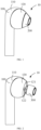
- an earphone 10 is provided according to an embodiment of the present disclosure.
- the earphone 10 includes a housing 100, a first eartip 200, a second eartip 300, and a speaker 130 (illustrated in FIG. 9 ).
- the first eartip 200 and the second eartip 300 is configured to detachably cooperate with the housing 100 to change a configuration of the earphone 10.
- the speaker 130 is received in the housing 100.
- the first eartip 200 is flexible and can be assembled to and detached from the housing 100.
- a distance between an end of the first eartip 200 away from the housing 100 and the housing 100 is L1.
- the first eartip 200 is made of silicon.
- the second eartip 300 is flexible, and can be assembled to and detached from the housing 100.
- a distance between an end of the second eartip 300 away from the housing 100 and the housing 100 is L2.
- L2 is greater than or equal to L1.
- a distance that the first eartip 200 extends in the auditory meatus 20 is smaller than a distance that the second eartip 300 extends in the auditory meatus 20 when received in the auditory meatus 20.
- the second eartip 300 is made of silicon.
- first cavity in a first vessel communicates with a second cavity in a second vessel by connecting the second vessel to the first vessel, such as a communicating vessel.
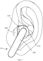
- the earphone 10 When the first eartip 200 is assembled to the housing 100, the earphone 10 has a structure of a semi-in-ear earphone. As illustrated in FIG. 5 , when a user wears the earphone 10 with the first eartip 200, the first eartip 200 is inserted into the auditory meatus 20, and a depth that the earphone 10 extends in the auditory meatus 20 is relative small.
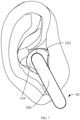
- the earphone 10 has a structure of an in-ear earphone. As illustrated in FIG.
- the second eartip 300 inserts into the auditory meatus 20, and a depth that the earphone 10 extends in the auditory meatus 20 is larger than that of the first eartip 200.
- the earphone 10 can switch between two configurations by equipping with the first eartip 200 and the second eartip 300.
- the two configurations include a first configuration and a second configuration.
- the first eartip 200 is detachably connected to the housing 100, and the first eartip 200 is deformed and in contact with the auditory meatus 20 when received in the auditory meatus 20.
- the second eartip 300 is detachably connected to the housing 100, and the second eartip 300 is deformed and in contact with the auditory meatus 20 when received in the auditory meatus 20.
- a distance that the first eartip 200 extends in the auditory meatus is smaller than a distance that the second eartip 300 extends in the auditory meatus when received in the auditory meatus.
- a front cavity 40 of the earphone 10 when the user wears the earphone 10 normally, the speaker 130, the housing 100, the auditory meatus 20, and an eardrum 30 of the user cooperatively form a cavity, which is referred to a front cavity 40 of the earphone 10.
- the acoustic characteristics of the front cavity 40 directly affect the acoustic performance of the earphone 10.
- the acoustic characteristics of the front cavity 40 mainly include the volume and airtightness of front cavity 40.
- the acoustic performance of the earphone 10 mainly includes a frequency response and a resonance frequency.
- the airtightness of the front cavity 40 of a semi-in-ear headphone and the airtightness of an in-ear headphone are significant different.
- the acoustic performance of the earphone 10 can be changed.
- the first eartip 200 and the second eartip 300 can be detachably assembled to the housing 100, which can change the distance that the earphone 10 extends in the auditory meatus. So that the earphone 10 can switch between a semi-in-ear earphone and an in-ear earphone, and the acoustic characteristics of the front cavity 40 may be adjusted, thereby adjusting the acoustic performance of the earphone 10.
- the earphone 10 works as a semi-in-ear earphone.
- the first eartip 200 is at least partially received in the auditory meatus 20, which does not generate pressure on the auditory meatus 20, and the first eartip 200 is not easy to detach from the auditory meatus 20, and the user experience is better.
- the first eartip 200 is received in the auditory meatus 20, the first eartip 200 can cooperate well with the auditory meatus 20, which may achieve a good sound insulation, and makes the airtightness of the front cavity 40 better, and improves the acoustic performance of the earphone 10.
- the earphone 10 defines a vent channel therein.
- the vent channel is configured to ventilate the housing 100 or the front cavity 40.
- the vent channel is a vent hole defined in the housing 100, and the vent hole is in communication with outside the housing 100.
- the vent channel may further comprise a notch defined in the housing 100 or defined in the second eartip 300, and the notch may be in communication with an interior cavity of the housing 100 and outside the housing 100.
- the vent channel may comprise a gap defined between the housing 100 and the second eartip 300, and the gap may be in communication with an interior cavity of the housing 100 and outside the housing 100.
- the earphone 10 works as an in-ear earphone.
- the second eartip 300 is at least partially received in the auditory meatus 20, and the gap or notch is in communication with the auditory meatus 20, which does not generate pressure on the auditory meatus 20, and the second eartip 300 is not easy to detach from the auditory meatus 20, and the user experience is better.
- the vent channel can reduce the airtightness of the front cavity 40, thereby avoiding a pressure difference between the auditory meatus 20 and the outside world, and thereby avoiding an echo of the sound when speaking.
- the second eartip 300 When the second eartip 300 is assembled to the housing 100, the depth that the earphone 10 extends in the auditory meatus 10 is smaller than that of a common in-ear earphone. So that the problem of intrusive feeling when the user wears the earphone 10 can be weakened.
- the airtightness of the front cavity 40 that is defined by the earphone 10 equipped with the first eartip 200 is substantially approximate to the airtightness of the front cavity 40 that is defined by the earphone 10 equipped with the second eartip 300. So that the earphone 10 may have similar acoustic characteristics in both conditions of the earphone 10 when equipped with the first eartip 200 and the second eartip 300. The sound qualities in both the two conditions are not easily affected.
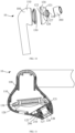
- the housing 100 includes a rear case 110, a front cover 120 connect to the rear case 110, and a sound emitting nozzle 126 connected to the front cover 120.
- the front cover 120 includes an end surface 121 and a side surface 1211 connected the end surface 121.
- the end surface 121 is disposed at an end of the front cover 120.
- the side surface 1211 is connected to an outer periphery of the end surface 121 to form an outer surface of the housing.
- the side surface 1211 is an exterior surface of the front cover 120.
- the front cover 120 caps at and seals the rear case 110.
- the front cover 120 and the rear case 110 cooperatively form an accommodating space.
- the speaker 130 is disposed in the accommodating space.
- a sound emitting part of the speaker 130 faces the front cover 120.
- the front cover 120 and the rear case 110 are made of plastic, synthetic resin, or metal, so that the housing 100 has a rigid structure and is not easy to be deformed. Therefore the electronic components in the housing 100 may be protected by the housing 100.
- the end surface 121 is disposed on an end of the front cover 120 away from the rear case 110.
- the sound emitting nozzle 126 is connected to and protrudes from the end surface 121.
- the sound emitting nozzle 126 is hollow for allowing sounds from the speaker 130 to transmit to outside.
- the sound emitting nozzle 126 is substantially cylindrical.
- the sound emitting nozzle 126 defines a first sound channel 128 communicating with the accommodating space. The sound emitted by the speaker 130 may pass through the first sound channel 128 and transmit to outside.
- the housing 100 includes a first holding portion 127 connected to the sound emitting nozzle 126.
- the first holding portion 127 is disposed on an end of the sound emitting nozzle 126 away from the end surface 121.
- the first holding portion 127 protrudes from an exterior surface of the sound emitting nozzle 126, and configured to engage with the first eartip 200 and the second eartip 300.
- the first holding portion 127 is substantially cyclic annular and surrounds the sound emitting nozzle 126.
- a diameter of the cross-sectional contour of the first holding portion 127 is larger than that of the sound emitting nozzle 126. So that when the first eartip 200 or the second eartip 300 is mounted on the housing 100, the first holding portion 127 can engage with the first eartip 200 or the second eartip 300, thereby avoiding the first eartip 200 or the second eartip 300 to detach from the housing 100.
- the first holding portion 127 may include one or more protrude portions disposed on the exterior surface of the sound emitting nozzle 126.
- the contour of a cross-section of the sound emitting nozzle 126 may also be a polygon such as a triangle, a quadrangle, or a pentagon, which is not specifically limited herein.
- the front cover 120, the sound emitting nozzle 126, and the first holding portion 127 cooperatively form an integrative structure.
- the first eartip 200 is mounted on and detached from the housing 100.
- the first eartip 200 defines a second sound channel 220 therein.
- the first sound channel 128 may communicate with the second sound channel 220. So that the sound emitted by the speaker 130 can pass through the first sound channel 128 and the second sound channel 220 and transmit to outside.
- the first eartip 200 is hollow, and includes a first interior wall 201 and a second holding portion 210.
- the first interior wall 201 defines the second sound channel 220.
- the first eartip 200 encircles the sound emitting nozzle 126 via the first interior wall 201.
- the second holding portion 210 is disposed on and protrudes from the first interior wall 201.
- the second holding portion 210 is disposed in the second sound channel 220.
- the second holding portion 210 is configured to engage with the first holding portion 127 so that the first eartip 200 is assembled to the housing 100 to avoid the first eartip 200 detaching from the housing 100.
- the second holding portion 210 is flexible and elastic.
- the second holding portion 210 is deformed and in contact with the first holding portion 127. Because the first holding portion 127 is harder and the second holding portion 210 is more flexible, the second holding portion 210 is deformed to provide a channel for the first holding portion 127 by squeezing, by which the second holding portion 210 can move to a side of the first holding portion 127 that facing the front cover 120. The first holding portion 127 and the second holding portion 210 are engaged with each other.
- the first eartip 200 may be made of a soft material such as rubber, resin, and silicon, and the first eartip 200 is an integrative structure.
- the second eartip 300 is mounted on and detached from the housing 100.
- the second eartip 300 defines a third sound channel 320 therein.
- the first sound channel 128 communicates with the third sound channel 320. So that the sound emitted by the speaker 130 can pass through the first sound channel 128 and the third sound channel 320 and transmit to outside.
- the second eartip 300 is hollow, and includes a second interior wall 301 and a third holding portion 310.
- the second interior wall 301 defines the third sound channel 320.
- the second eartip 300 encircles the sound emitting nozzle 126 via the second interior wall 301.
- the third holding portion 310 is disposed on and protrudes from the second interior wall 301.
- the third holding portion 310 is disposed in the third sound channel 320.
- the third holding portion 310 is configured to engage with the first holding portion 127 so that the second eartip 300 can be assembled to the housing 100 to avoid the second eartip 300 detaching from the housing 100.
- the third holding portion 310 is disposed in the third sound channel 310 is flexible and is elastic.
- the third holding portion 310 is deformed and in contact with and the first holding portion 127. Because the first holding portion 127 is harder and the third holding portion 310 is more flexible, the third holding portion 310 is deformed to provide a channel for the first holding portion 127 by squeezing, by which the third holding portion 310 can move to a side of the first holding portion 127 that facing the front cover 120. The first holding portion 127 and the third holding portion 310 are engaged with each other.
- the second eartip 300 may be made of soft material such as rubber, resin, and silicon, and the second eartip 300 is an integrative structure.
- the front cover 120 defines a vent hole 122 therein.
- the vent hole 122 extends to the end surface 121, that is, the vent hole 122 penetrates the front cover 120 in a thickness direction of the front cover 120. So that the air in the housing 100 can flow out.
- the vent hole 122 is adjacent to the sound emitting nozzle 126 but apart from the sound emitting nozzle 126 for a certain distance.
- the first eartip 200 is mounted on the housing 100, the first eartip 200 is stacked on the end surface 121 and in contact with the side surface 1211 smoothly.
- the vent hole 122 is covered by the first eartip 200.
- the contour of the edge of the first eartip 200 coincides with the contour of the edge of the end surface 121.
- the first eartip 200 and the housing 100 form an integral shape, and the first eartip 200 covers and seals the vent hole 122.
- the distance between an end of the first eartip 200 away from the housing 100 and the end surface 121 is L1.
- the first eartip 200 When the user wears the earphone 10 with the first eartip 200, the first eartip 200 is inserted into the auditory meatus 20.
- the depth that the first eartip 200 extends in the auditory meatus 20 is relatively small, and the rest of the earphone 10 is maintained outside the auditory meatus 20.
- the first eartip 200 is closely fitted to the auditory meatus 20 and can be deformed according to the shape of the auditory meatus 20. So that the seal between the earphone 10 and the auditory meatus 20 is better, and the airtightness of the front cavity 40 is better than a common semi-in-ear headphone. Therefore a sound insulation of the headphones 10 is better, and the low-frequency response of acoustic performance is better.
- the first eartip 200 may be designed in different sizes according to different sizes of the auditory meatus 20 of people, so that the earphone 10 of the present disclosure can be adapted to different people.
- an outside diameter of the first eartip 200 is smaller than that of the second eartip 300.
- an area surrounded by the contour of the edge of the second eartip 300 is smaller than an area surrounded by the contour of the edge of the end surface 121.
- the second eartip 300 is apart from the end surface 121.
- the distance between the end of the second eartip 300 away from the housing 100 and the end surface 121 is L2.
- L2 is greater than L1. Therefore, a distance that the first eartip 200 extends in the auditory meatus 20 is smaller than a distance that the second eartip 300 extends in the auditory meatus 20 when received in the auditory meatus.
- the second eartip 300 When the user wears the earphone 10 with the second eartip 300, the second eartip 300 is inserted into the auditory meatus 20. A depth that the second eartip 300 extends in the auditory meatus 20 is relatively larger. The rest of the earphone 10 is maintained outside the auditory meatus 20. The second eartip 300 can be closely fitted to the auditory meatus 20 and can be deformed according to the shape of the auditory meatus 20 to improve the comfort of the user.
- the vent hole 122 of the earphone 10 will not be covered by the second eartip 300, so that the air in the housing 100 can flow out from the vent hole 122, which can reduce the airtightness of the front cavity 40, and can solve the problem of poor wearing experience caused by the difference in air pressure between the inside and outside the auditory meatus 20, also makes the airtightness and acoustic characteristics of the earphone 10 that works as the in-ear structure closer to that of the earphone 10 works as the semi-in-ear earphone. Therefore, the sound qualities of the earphone 10 that works as the semi-in-ear and the in-ear are substantially the same.
- the second eartip 300 may be designed in different sizes according to different sizes of the auditory meatus 20 of people, so that the earphone 10 of the present disclosure can be adapted to different people.
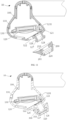
- the sound emitting nozzle 126 protrudes from the end surface 121 of the front cover 12.
- the vent hole 122 is defined in the wall of the sound emitting nozzle 126 and is located at an end of the sound emitting nozzle 126 adjacent to the end surface 121.
- the vent hole 122 is covered and sealed by the second holding portion 210.
- the vent hole 122 is located by a side of the third holding portion 310 adjacent to the end surface 121, so that the vent hole 122 is not sealed by the third holding portion 310. That is, the vent hole 122 is not covered or sealed by the second eartip 300 and exposed, so that the air in the first sound channel 128 can flow out from the vent hole 122, which can reduce the airtightness of the front cavity 40, and can solve the problem of poor wearing experience caused by the difference in air pressure between the inside and outside the auditory meatus 20, also makes the airtightness and acoustic characteristics of the earphone 10 that works as the in-ear structure closer to that of the earphone 10 works as the semi-in-ear earphone. Therefore, the sound qualities of the earphone 10 that works as the semi-in-ear and the in-ear are substantially the same.
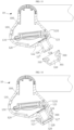
- the vent channel comprises a gap defined by the second eartip 300 and the housing 100.
- the third holding portion 310 is engaged with the first holding portion 127.
- the gap 123 defines the vent channel of the earphone 10. The airtightness between the second eartip 300 and the sound emitting nozzle 126 may be reduced via the gap 123.
- the air in the housing 100 can pass through the first sound channel 128, the third sound channel 320, and the gap 123 in sequence and flow out, thereby reducing the airtightness of the front cavity 40, and solving the problem of poor wearing experience caused by the difference in air pressure between the inside and outside the auditory meatus 20, also makes the airtightness and acoustic characteristics of the earphone 10 that works as the in-ear structure closer to that of the earphone 10 works as the semi-in-ear earphone. Therefore, the sound qualities of the earphone 10 that works as the semi-in-ear and the in-ear are substantially the same.
- the vent channel comprises a notch defined in the second eartip 300.
- the third holding portion 310 of the second eartip 300 defines a notch 124 therein.
- the second eartip 300 is mounted on the housing 100, the third holding portion 310 is engaged with the first holding portion 127.
- the notch 124 in the third holding portion 310 defines the vent channel of the earphone 10.
- the air in the housing 100 can pass through the first sound channel 128, the third sound channel 320, and the gap 123 in sequence and flow out, thereby reducing the airtightness of the front cavity 40, and solving the problem of poor wearing experience caused by the difference in air pressure between the inside and outside the auditory meatus 20, also makes the airtightness and acoustic characteristics of the earphone 10 that works as the in-ear structure closer to that of the earphone 10 works as the semi-in-ear earphone. Therefore, the sound qualities of the earphone 10 that works as the semi-in-ear and the in-ear are substantially the same.
- the first eartip 200 and the second eartip 300 having different sizes and shapes can be detachably mounted on the housing 100.
- the depth of the ear of the earphone 10 may be changed via the first eartip 200 and the second eartip 300. So that the earphone 10 can be used as a semi-in-ear earphone or an in-ear earphone, which can adjust the acoustic characteristics of the front cavity 40, thereby adjusting the acoustic performance of the headphones 10.
- the earphone 10 works as a semi-in-ear earphone.
- the first eartip 200 When the user wears the earphone 10 with the first eartip 200, the first eartip 200 is inserted into the auditory meatus 20, which does not generate pressure on the auditory meatus 20 and is not easy to detach from the auditory meatus 20, and the user experience is better.
- the first eartip 200 When the first eartip 200 is received in the auditory meatus 20, the first eartip 200 can cooperate well with the auditory meatus 20, which may achieve a good sound insulation, and makes the airtightness of the front cavity 40 better, and improves the acoustic performance of the earphone 10.
- the earphone 10 works as an in-ear earphone.
- the second eartip 300 is inserted into the auditory meatus 20, which does not generate pressure on the auditory meatus 20 and is not easy to detach from the auditory meatus 20, and the user experience is better.
- the second eartip 300 can reduce the airtightness of the front cavity 40 via the air vent hole 122 and optionally the air vent channel, thereby avoiding a pressure difference between the auditory meatus 20 and the outside world, and thereby avoiding an echo of the sound when speaking. Therefore an openness of the sound quality of the earphone 10 is improved.
- the depth that the earphone 10 extends in the auditory meatus 10 is smaller than that of a common in-ear earphone. So that the problem of intrusive feeling when the user wears the earphone 10 can be weakened.
- the airtightness of the front cavity 40 that is defined by the earphone 10 with the first eartip 200 is substantially approximate to the airtightness of the front cavity 40 that is defined by the earphone 10 with the second eartip 300. So that the earphone 10 may have similar acoustic characteristics in both conditions of the earphone 10 when equipped with the first eartip 200 and the second eartip 300. The sound qualities of both the two conditions are not easily affected.
Landscapes
- Physics & Mathematics (AREA)
- Engineering & Computer Science (AREA)
- Acoustics & Sound (AREA)
- Signal Processing (AREA)
- Health & Medical Sciences (AREA)
- Otolaryngology (AREA)
- Manufacturing & Machinery (AREA)
- Electromagnetism (AREA)
- Headphones And Earphones (AREA)
Claims (15)
- Kopfhörer (10), Folgendes umfassend:ein Gehäuse (100), das einen Innenraum darin definiert, wobei das Gehäuse (100) eine vordere Abdeckung (120) und eine Schallemissionsdüse (126) umfasst, die mit der vorderen Abdeckung (120) verbunden ist; wobei die vordere Abdeckung (120) eine Endfläche (121) umfasst, die an einem Ende davon angeordnet ist; wobei die Schallemissionsdüse (126) aus der Endfläche (121) vorsteht; wobei das Gehäuse (100) ein Belüftungsloch (122) in der vorderen Abdeckung (120) definiert; wobei das Belüftungsloch (122) die Endfläche (121) durchdringt;ein erstes Ohrstück (200), das eingerichtet ist, um an der Schallemissionsdüse (126) befestigt zu werden; undein zweites Ohrstück (300), das eingerichtet ist, um an der Schallemissionsdüse (126) befestigt zu werden;wobei das erste Ohrstück (200) oder das zweite Ohrstück selektiv an dem Gehäuse (100) befestigt ist;wobei,wenn das zweite Ohrstück (300) an der Schallemissionsdüse (126) befestigt ist, der Kopfhörer (10) als ein Im-Ohr-Kopfhörer arbeitet und es eine Lücke zwischen dem zweiten Ohrstück (300) und der Endfläche (121) gibt, so dass das Belüftungsloch (122) in der Endfläche (121) freiliegt und mit dem Innenraum und dem Äußeren des Gehäuses (100) kommuniziert; undwenn das erste Ohrstück (200) an dem Gehäuse (100) befestigt ist, der Kopfhörer (10) als ein Semi-Im-Ohr-Kopfhörer arbeitet und das erste Ohrstück (200) in Kontakt mit der Endfläche (121) ist, wodurch das Belüftungsloch (122) abgedichtet wird.
- Kopfhörer (10) nach Anspruch 1, wobei die vordere Abdeckung (120) den Innenraum definiert, die Schallemissionsdüse (126) einen ersten Schallkanal (128) darin definiert, der erste Schallkanal (128) mit dem Innenraum kommuniziert; das erste Ohrstück (200) einen zweiten Schallkanal (220) definiert, der zweite Schallkanal (220) mit dem ersten Schallkanal (128) kommuniziert, wenn das erste Ohrstück (200) an dem Gehäuse (100) befestigt ist; das zweite Ohrstück (300) einen dritten Schallkanal (320) definiert; der dritte Schallkanal (320) mit dem ersten Schallkanal (128) kommuniziert, wenn das zweite Ohrstück (300) an dem Gehäuse (100) befestigt ist.
- Kopfhörer (10) nach Anspruch 2, wobei das Gehäuse (100) einen ersten Halteabschnitt (127) umfasst, der mit der Schallemissionsdüse (126) verbunden ist; wobei der erste Halteabschnitt (127) selektiv mit dem ersten Ohrstück (200) oder mit dem zweiten Ohrstück (300) zusammenwirkt.
- Kopfhörer (10) nach Anspruch 3, wobei das erste Ohrstück (200) einen zweiten Halteabschnitt (210) umfasst, der eingerichtet ist, um mit dem ersten Halteabschnitt (127) in Eingriff zu treten, um das erste Ohrstück (200) mit der Schallemissionsdüse (126) zu verbinden; wobei das zweite Ohrstück (300) einen dritten Halteabschnitt (310) umfasst, der eingerichtet ist, um mit dem ersten Halteabschnitt (127) in Eingriff zu treten, um das zweite Ohrstück (300) mit der Schallemissionsdüse (126) zu verbinden.
- Kopfhörer (10) nach Anspruch 4, wobei der dritte Halteabschnitt (310) des zweiten Ohrstücks (300) eine Aussparung (124) darin definiert.
- Kopfhörer (10) nach Anspruch 3, wobei der erste Halteabschnitt (127) mindestens einen vorstehenden Abschnitt umfasst, der an der Außenfläche der Schallemissionsdüse (126) angeordnet ist.
- Kopfhörer (10) nach einem der Ansprüche 3 bis 6, wobei das Gehäuse (100) eine hintere Kapsel (110) umfasst, die mit der vorderen Abdeckung (120) verbunden ist; die Endfläche (121) an einem Ende davon von der hinteren Kapsel (110) weg angeordnet ist.
- Kopfhörer (10) nach Anspruch 1, wobei, wenn das zweite Ohrstück (300) an der Schallemissionsdüse (126) befestigt ist, eine Fläche, die von einer Kontur einer Kante des zweiten Ohrstücks (300) umgeben ist, kleiner ist als eine Fläche, die von einer Kontur einer Kante der Endfläche (121) umgeben ist.
- Kopfhörer (10) nach Anspruch 7, wobei das Belüftungsloch (122) der Schallemissionsdüse (126) benachbart ist.
- Kopfhörer (10) nach einem der Ansprüche 7 bis 9, wobei der Innenraum durch die hintere Kapsel (110) abgedeckt ist; der Kopfhörer (10) einen Lautsprecher umfasst, der in dem Innenraum beherbergt wird.
- Kopfhörer (10) nach einem der Ansprüche 7 bis 10, wobei das zweite Ohrstück (300) eine Aussparung (124) in einer Innenfläche davon definiert.
- Kopfhörer (10) nach einem der Ansprüche 7 bis 11, wobei eine Kontur des ersten Ohrstücks (200) mit einer Kontur der Endfläche (121) zusammenfällt.
- Kopfhörer (10) nach einem der Ansprüche 2 bis 4, wobei das erste Ohrstück (200) die Schallemissionsdüse (126) umgibt und in Presspassung mit ihr ist, wenn es an dem Gehäuse (100) befestigt ist; wobei das zweite Ohrstück (300) die Schallemissionsdüse (126) umgibt und in Spielpassung mit ihr ist, wenn das zweite Ohrstück (300) an dem Gehäuse (100) befestigt ist.
- Kopfhörer (10) nach einem der Ansprüche 2 bis 4, wobei das zweite Ohrstück (300) die Schallemissionsdüse (126) umgibt und in Presspassung mit ihr ist, wenn das zweite Ohrstück (300) an dem Gehäuse (100) befestigt ist.
- Kopfhörer (10) nach einem der Ansprüche 1 bis 14, wobei das erste Ohrstück (200) und das zweite Ohrstück (300) aus Silikon angefertigt sind.
Applications Claiming Priority (2)
| Application Number | Priority Date | Filing Date | Title |
|---|---|---|---|
| CN201910449252.5A CN112019959B (zh) | 2019-05-28 | 2019-05-28 | 耳机 |
| CN201920788583.7U CN210093459U (zh) | 2019-05-28 | 2019-05-28 | 耳机 |
Publications (2)
| Publication Number | Publication Date |
|---|---|
| EP3745735A1 EP3745735A1 (de) | 2020-12-02 |
| EP3745735B1 true EP3745735B1 (de) | 2024-12-18 |
Family
ID=70736632
Family Applications (1)
| Application Number | Title | Priority Date | Filing Date |
|---|---|---|---|
| EP20174549.4A Active EP3745735B1 (de) | 2019-05-28 | 2020-05-14 | Kopfhörer der einen abgedichteten belüftungskanal mit einem ersten ohrstück und einen offenen belüftungskanal mit einem zweiten ohrstück definiert |
Country Status (3)
| Country | Link |
|---|---|
| US (2) | US11197080B2 (de) |
| EP (1) | EP3745735B1 (de) |
| WO (1) | WO2020238619A1 (de) |
Families Citing this family (39)
| Publication number | Priority date | Publication date | Assignee | Title |
|---|---|---|---|---|
| JP2022506786A (ja) * | 2018-11-14 | 2022-01-17 | オルフェオ サウンドワークス コーポレーション | 発話者の音声復元機能を有するイヤーセット |
| US10993054B2 (en) * | 2018-11-21 | 2021-04-27 | Starkey Laboratories, Inc. | Wax protection for in-canal hearing device |
| CN113016193B (zh) * | 2018-11-25 | 2024-02-23 | 株式会社慕悟 | 耳机 |
| WO2020238619A1 (en) * | 2019-05-28 | 2020-12-03 | Guangdong Oppo Mobile Telecommunications Corp., Ltd. | Earphone |
| WO2021030811A1 (en) * | 2019-08-15 | 2021-02-18 | Barnacka Anna | Earbud for detecting biosignals from and presenting audio signals at an inner ear canal and method therefor |
| USD943553S1 (en) * | 2019-09-04 | 2022-02-15 | Shenzhen Duntuo Electronics Co., Ltd | Set of earphones and charging case |
| USD953739S1 (en) * | 2019-09-13 | 2022-06-07 | Apple Inc. | Case |
| USD907009S1 (en) * | 2019-09-20 | 2021-01-05 | Apple Inc. | Case with earphones |
| USD943554S1 (en) * | 2019-10-08 | 2022-02-15 | Shenzhen Duntuo Electronics Co., Ltd | Set of earphones and charging case |
| USD912017S1 (en) * | 2020-08-10 | 2021-03-02 | Shenzhen Weixin Yiheng Technology Co., Ltd | Wireless headset |
| USD958117S1 (en) * | 2020-09-21 | 2022-07-19 | Realme Mobile Telecommunications (Shenzhen) Co., Ltd. | Case with earphones |
| USD928126S1 (en) * | 2020-09-28 | 2021-08-17 | Xinying Chen | Wireless earphone |
| USD956720S1 (en) * | 2020-09-30 | 2022-07-05 | Shenzhen Zio Communication Technology Co., Ltd. | Earphone |
| USD981373S1 (en) * | 2020-10-12 | 2023-03-21 | Oneplus Technology (Shenzhen) Co., Ltd. | Earphone |
| USD960131S1 (en) * | 2020-11-10 | 2022-08-09 | Shenghui Zhu | Pair of earphones |
| USD957367S1 (en) * | 2020-12-01 | 2022-07-12 | Beijing Edifier Technology Co., Ltd. | Earphone |
| USD924852S1 (en) * | 2021-01-12 | 2021-07-13 | Shenzhen Shengyuansheng Technology Co., Ltd. | Earphones |
| USD936037S1 (en) * | 2021-01-19 | 2021-11-16 | Shenzhen Baifan Technology Co., Ltd. | Earphone |
| USD990455S1 (en) * | 2021-02-01 | 2023-06-27 | Realme Mobile Telecommunications (Shenzhen) Co., Ltd. | Earphone |
| USD1009836S1 (en) * | 2021-02-04 | 2024-01-02 | Realme Mobile Telecommunications (Shenzhen) Co., Ltd. | Earphone |
| USD1000424S1 (en) * | 2021-03-19 | 2023-10-03 | Oneplus Technology (Shenzhen) Co., Ltd. | Wireless earphone |
| USD980194S1 (en) * | 2021-04-14 | 2023-03-07 | Justin Lee | Earphone |
| CN113316056B (zh) * | 2021-05-26 | 2023-03-24 | 歌尔科技有限公司 | 耳机和电子产品 |
| USD980825S1 (en) * | 2021-06-14 | 2023-03-14 | Navajo Manufacturing Company, Inc. | Earbud |
| USD1021864S1 (en) * | 2021-07-19 | 2024-04-09 | Zound Industries International Ab | Earbud |
| CN113596666B (zh) * | 2021-07-30 | 2022-11-01 | 歌尔科技有限公司 | 耳机结构 |
| WO2023016504A1 (zh) * | 2021-08-10 | 2023-02-16 | Oppo广东移动通信有限公司 | 耳机声学组件、耳机壳体、耳机以及耳机套件 |
| USD1038084S1 (en) * | 2021-08-19 | 2024-08-06 | Harman International Industries, Incorporated | Headphone |
| USD1019596S1 (en) * | 2021-10-23 | 2024-03-26 | Scud (Fujian) Electronics Co., Ltd | Pair of wireless earphones |
| CN114245254B (zh) * | 2021-11-05 | 2022-11-08 | 北京荣耀终端有限公司 | 耳机 |
| US12155986B2 (en) | 2021-12-13 | 2024-11-26 | Samsung Electronics Co., Ltd. | Acoustic device and electronic device including the same |
| USD1002576S1 (en) * | 2022-04-25 | 2023-10-24 | Besing Technology (Shenzhen) Co., Ltd. | Wireless earphones with charging case |
| USD1047961S1 (en) * | 2022-08-30 | 2024-10-22 | Harman International Industries, Incorporated | Headphone |
| SE546442C2 (en) * | 2022-09-05 | 2024-11-05 | Marshall Group Ab Publ | Reconfigurable speaker module |
| JP1755974S (ja) * | 2022-09-19 | 2023-10-23 | ワイヤレスイヤホン | |
| USD1060313S1 (en) * | 2022-12-16 | 2025-02-04 | Harman International Industries, Incorporated | Headphone |
| EP4456552A1 (de) * | 2023-04-25 | 2024-10-30 | GN Audio A/S | Ohrstück |
| CN116389966B (zh) * | 2023-05-24 | 2023-08-22 | 成都弱水科技有限公司 | 一种蓝牙耳机 |
| USD1105042S1 (en) * | 2024-05-31 | 2025-12-09 | Dongguan Hengchang Mould Plastic Co., Ltd | Pair of earphones |
Citations (1)
| Publication number | Priority date | Publication date | Assignee | Title |
|---|---|---|---|---|
| CN205793193U (zh) * | 2016-06-21 | 2016-12-07 | 歌尔股份有限公司 | 一种入耳深度可变的耳机 |
Family Cites Families (20)
| Publication number | Priority date | Publication date | Assignee | Title |
|---|---|---|---|---|
| US8774435B2 (en) * | 2008-07-23 | 2014-07-08 | Asius Technologies, Llc | Audio device, system and method |
| US8189846B2 (en) * | 2008-09-05 | 2012-05-29 | Apple Inc. | Vented in-the-ear headphone |
| CN102119535A (zh) * | 2009-05-13 | 2011-07-06 | 松下电器产业株式会社 | 耳机装置及耳机装置主体 |
| CN202004931U (zh) * | 2010-12-17 | 2011-10-05 | 歌尔声学股份有限公司 | 入耳式耳机声压平衡系统 |
| US8885866B2 (en) * | 2011-07-22 | 2014-11-11 | Panasonic Corporation | Earphone |
| CN202587329U (zh) * | 2012-04-24 | 2012-12-05 | 富港电子(东莞)有限公司 | 入耳式耳机 |
| US9364648B2 (en) * | 2012-05-30 | 2016-06-14 | Tusker Medical, Inc. | Adhesive earplugs useful for sealing the ear canal |
| CN105451109B (zh) * | 2014-09-30 | 2019-09-20 | 深圳市三诺数字科技有限公司 | 一种可以用户端自由调节音效的入耳式耳机 |
| CN204578734U (zh) * | 2015-04-24 | 2015-08-19 | 加一联创电子科技有限公司 | 一种入耳式耳机 |
| US10433045B2 (en) * | 2015-09-30 | 2019-10-01 | Apple Inc. | Earbud stability anchor feature |
| CN205142465U (zh) | 2015-10-30 | 2016-04-06 | 易力声科技(深圳)有限公司 | 一种可调音入耳式耳机 |
| AU2016380257A1 (en) * | 2015-12-28 | 2018-06-28 | Hearing Components, Inc. | Earphone tip with universal sound port attachment core |
| CN205622807U (zh) * | 2016-04-28 | 2016-10-05 | 歌尔声学股份有限公司 | 两用耳机 |
| CN109076277B (zh) * | 2016-09-06 | 2020-10-23 | 苹果公司 | 具有用于固定到用户的翼尖的耳机组件 |
| US10264365B2 (en) * | 2017-04-10 | 2019-04-16 | Bose Corporation | User-specified occluding in-ear listening devices |
| CN108429971B (zh) * | 2018-05-28 | 2019-10-18 | Oppo广东移动通信有限公司 | 耳机控制方法及耳机 |
| US10970868B2 (en) * | 2018-09-04 | 2021-04-06 | Bose Corporation | Computer-implemented tools and methods for determining optimal ear tip fitment |
| US10986433B2 (en) * | 2018-09-28 | 2021-04-20 | Apple Inc. | Eartips for coupling via wireform attachment mechanisms |
| WO2020238619A1 (en) * | 2019-05-28 | 2020-12-03 | Guangdong Oppo Mobile Telecommunications Corp., Ltd. | Earphone |
| CN210093459U (zh) * | 2019-05-28 | 2020-02-18 | Oppo广东移动通信有限公司 | 耳机 |
-
2020
- 2020-05-12 WO PCT/CN2020/089854 patent/WO2020238619A1/en not_active Ceased
- 2020-05-14 EP EP20174549.4A patent/EP3745735B1/de active Active
- 2020-05-21 US US16/880,511 patent/US11197080B2/en active Active
-
2021
- 2021-12-03 US US17/542,037 patent/US11825260B2/en active Active
Patent Citations (1)
| Publication number | Priority date | Publication date | Assignee | Title |
|---|---|---|---|---|
| CN205793193U (zh) * | 2016-06-21 | 2016-12-07 | 歌尔股份有限公司 | 一种入耳深度可变的耳机 |
Also Published As
| Publication number | Publication date |
|---|---|
| EP3745735A1 (de) | 2020-12-02 |
| WO2020238619A1 (en) | 2020-12-03 |
| US11825260B2 (en) | 2023-11-21 |
| US20220095034A1 (en) | 2022-03-24 |
| US20200382856A1 (en) | 2020-12-03 |
| US11197080B2 (en) | 2021-12-07 |
Similar Documents
| Publication | Publication Date | Title |
|---|---|---|
| EP3745735B1 (de) | Kopfhörer der einen abgedichteten belüftungskanal mit einem ersten ohrstück und einen offenen belüftungskanal mit einem zweiten ohrstück definiert | |
| JP5695703B2 (ja) | 音響チューニングメカニズムを有するイヤホン | |
| KR101583627B1 (ko) | 제어된 음향 누설 포트를 갖는 이어폰 | |
| CN102648639B (zh) | 耳机 | |
| EP3332555B1 (de) | Geräuschreduktion mit im-ohr-kopfhörer | |
| CN210093459U (zh) | 耳机 | |
| JP2015195444A (ja) | 当接部材及びイヤホン | |
| CN210202053U (zh) | 一种耳机的调音结构和入耳式耳机 | |
| CN211880586U (zh) | 头戴式耳机调音结构及耳壳组件 | |
| CN216122812U (zh) | 可实现入耳式或半入耳式的tws耳机 | |
| CN210202054U (zh) | 一种耳机的调音结构和入耳式耳机 | |
| CN112019959B (zh) | 耳机 | |
| CN212231716U (zh) | 一种耳机 | |
| JP2017228990A (ja) | イヤホン | |
| CN118104251B (zh) | 开放式耳机 | |
| JP7427171B1 (ja) | オープン型イヤホン | |
| CN222395794U (zh) | 耳机 | |
| KR200245053Y1 (ko) | 이어피스에 통기홀을 갖는 이어폰 | |
| CN111741398A (zh) | 一种耳机 | |
| HK1208111B (en) | An earphone having a controlled acoustic leak port |
Legal Events
| Date | Code | Title | Description |
|---|---|---|---|
| PUAI | Public reference made under article 153(3) epc to a published international application that has entered the european phase |
Free format text: ORIGINAL CODE: 0009012 |
|
| STAA | Information on the status of an ep patent application or granted ep patent |
Free format text: STATUS: THE APPLICATION HAS BEEN PUBLISHED |
|
| AK | Designated contracting states |
Kind code of ref document: A1 Designated state(s): AL AT BE BG CH CY CZ DE DK EE ES FI FR GB GR HR HU IE IS IT LI LT LU LV MC MK MT NL NO PL PT RO RS SE SI SK SM TR |
|
| AX | Request for extension of the european patent |
Extension state: BA ME |
|
| STAA | Information on the status of an ep patent application or granted ep patent |
Free format text: STATUS: REQUEST FOR EXAMINATION WAS MADE |
|
| 17P | Request for examination filed |
Effective date: 20210531 |
|
| RBV | Designated contracting states (corrected) |
Designated state(s): AL AT BE BG CH CY CZ DE DK EE ES FI FR GB GR HR HU IE IS IT LI LT LU LV MC MK MT NL NO PL PT RO RS SE SI SK SM TR |
|
| STAA | Information on the status of an ep patent application or granted ep patent |
Free format text: STATUS: EXAMINATION IS IN PROGRESS |
|
| 17Q | First examination report despatched |
Effective date: 20221207 |
|
| GRAP | Despatch of communication of intention to grant a patent |
Free format text: ORIGINAL CODE: EPIDOSNIGR1 |
|
| STAA | Information on the status of an ep patent application or granted ep patent |
Free format text: STATUS: GRANT OF PATENT IS INTENDED |
|
| INTG | Intention to grant announced |
Effective date: 20240712 |
|
| GRAS | Grant fee paid |
Free format text: ORIGINAL CODE: EPIDOSNIGR3 |
|
| GRAA | (expected) grant |
Free format text: ORIGINAL CODE: 0009210 |
|
| STAA | Information on the status of an ep patent application or granted ep patent |
Free format text: STATUS: THE PATENT HAS BEEN GRANTED |
|
| AK | Designated contracting states |
Kind code of ref document: B1 Designated state(s): AL AT BE BG CH CY CZ DE DK EE ES FI FR GB GR HR HU IE IS IT LI LT LU LV MC MK MT NL NO PL PT RO RS SE SI SK SM TR |
|
| REG | Reference to a national code |
Ref country code: CH Ref legal event code: EP |
|
| REG | Reference to a national code |
Ref country code: DE Ref legal event code: R096 Ref document number: 602020043231 Country of ref document: DE |
|
| REG | Reference to a national code |
Ref country code: IE Ref legal event code: FG4D |
|
| P01 | Opt-out of the competence of the unified patent court (upc) registered |
Free format text: CASE NUMBER: APP_9773/2025 Effective date: 20250226 |
|
| REG | Reference to a national code |
Ref country code: LT Ref legal event code: MG9D |
|
| PG25 | Lapsed in a contracting state [announced via postgrant information from national office to epo] |
Ref country code: HR Free format text: LAPSE BECAUSE OF FAILURE TO SUBMIT A TRANSLATION OF THE DESCRIPTION OR TO PAY THE FEE WITHIN THE PRESCRIBED TIME-LIMIT Effective date: 20241218 |
|
| PG25 | Lapsed in a contracting state [announced via postgrant information from national office to epo] |
Ref country code: FI Free format text: LAPSE BECAUSE OF FAILURE TO SUBMIT A TRANSLATION OF THE DESCRIPTION OR TO PAY THE FEE WITHIN THE PRESCRIBED TIME-LIMIT Effective date: 20241218 |
|
| PG25 | Lapsed in a contracting state [announced via postgrant information from national office to epo] |
Ref country code: BG Free format text: LAPSE BECAUSE OF FAILURE TO SUBMIT A TRANSLATION OF THE DESCRIPTION OR TO PAY THE FEE WITHIN THE PRESCRIBED TIME-LIMIT Effective date: 20241218 |
|
| PG25 | Lapsed in a contracting state [announced via postgrant information from national office to epo] |
Ref country code: NO Free format text: LAPSE BECAUSE OF FAILURE TO SUBMIT A TRANSLATION OF THE DESCRIPTION OR TO PAY THE FEE WITHIN THE PRESCRIBED TIME-LIMIT Effective date: 20250318 |
|
| REG | Reference to a national code |
Ref country code: NL Ref legal event code: MP Effective date: 20241218 |
|
| PG25 | Lapsed in a contracting state [announced via postgrant information from national office to epo] |
Ref country code: GR Free format text: LAPSE BECAUSE OF FAILURE TO SUBMIT A TRANSLATION OF THE DESCRIPTION OR TO PAY THE FEE WITHIN THE PRESCRIBED TIME-LIMIT Effective date: 20250319 Ref country code: LV Free format text: LAPSE BECAUSE OF FAILURE TO SUBMIT A TRANSLATION OF THE DESCRIPTION OR TO PAY THE FEE WITHIN THE PRESCRIBED TIME-LIMIT Effective date: 20241218 |
|
| PG25 | Lapsed in a contracting state [announced via postgrant information from national office to epo] |
Ref country code: RS Free format text: LAPSE BECAUSE OF FAILURE TO SUBMIT A TRANSLATION OF THE DESCRIPTION OR TO PAY THE FEE WITHIN THE PRESCRIBED TIME-LIMIT Effective date: 20250318 |
|
| PG25 | Lapsed in a contracting state [announced via postgrant information from national office to epo] |
Ref country code: NL Free format text: LAPSE BECAUSE OF FAILURE TO SUBMIT A TRANSLATION OF THE DESCRIPTION OR TO PAY THE FEE WITHIN THE PRESCRIBED TIME-LIMIT Effective date: 20241218 |
|
| REG | Reference to a national code |
Ref country code: AT Ref legal event code: MK05 Ref document number: 1753230 Country of ref document: AT Kind code of ref document: T Effective date: 20241218 |
|
| PG25 | Lapsed in a contracting state [announced via postgrant information from national office to epo] |
Ref country code: SM Free format text: LAPSE BECAUSE OF FAILURE TO SUBMIT A TRANSLATION OF THE DESCRIPTION OR TO PAY THE FEE WITHIN THE PRESCRIBED TIME-LIMIT Effective date: 20241218 |
|
| PG25 | Lapsed in a contracting state [announced via postgrant information from national office to epo] |
Ref country code: PL Free format text: LAPSE BECAUSE OF FAILURE TO SUBMIT A TRANSLATION OF THE DESCRIPTION OR TO PAY THE FEE WITHIN THE PRESCRIBED TIME-LIMIT Effective date: 20241218 |
|
| PGFP | Annual fee paid to national office [announced via postgrant information from national office to epo] |
Ref country code: DE Payment date: 20250519 Year of fee payment: 6 |
|
| PG25 | Lapsed in a contracting state [announced via postgrant information from national office to epo] |
Ref country code: ES Free format text: LAPSE BECAUSE OF FAILURE TO SUBMIT A TRANSLATION OF THE DESCRIPTION OR TO PAY THE FEE WITHIN THE PRESCRIBED TIME-LIMIT Effective date: 20241218 |
|
| PG25 | Lapsed in a contracting state [announced via postgrant information from national office to epo] |
Ref country code: IS Free format text: LAPSE BECAUSE OF FAILURE TO SUBMIT A TRANSLATION OF THE DESCRIPTION OR TO PAY THE FEE WITHIN THE PRESCRIBED TIME-LIMIT Effective date: 20250418 |
|
| PG25 | Lapsed in a contracting state [announced via postgrant information from national office to epo] |
Ref country code: PT Free format text: LAPSE BECAUSE OF FAILURE TO SUBMIT A TRANSLATION OF THE DESCRIPTION OR TO PAY THE FEE WITHIN THE PRESCRIBED TIME-LIMIT Effective date: 20250421 |
|
| PG25 | Lapsed in a contracting state [announced via postgrant information from national office to epo] |
Ref country code: EE Free format text: LAPSE BECAUSE OF FAILURE TO SUBMIT A TRANSLATION OF THE DESCRIPTION OR TO PAY THE FEE WITHIN THE PRESCRIBED TIME-LIMIT Effective date: 20241218 |
|
| PG25 | Lapsed in a contracting state [announced via postgrant information from national office to epo] |
Ref country code: AT Free format text: LAPSE BECAUSE OF FAILURE TO SUBMIT A TRANSLATION OF THE DESCRIPTION OR TO PAY THE FEE WITHIN THE PRESCRIBED TIME-LIMIT Effective date: 20241218 Ref country code: RO Free format text: LAPSE BECAUSE OF FAILURE TO SUBMIT A TRANSLATION OF THE DESCRIPTION OR TO PAY THE FEE WITHIN THE PRESCRIBED TIME-LIMIT Effective date: 20241218 |
|
| PG25 | Lapsed in a contracting state [announced via postgrant information from national office to epo] |
Ref country code: SK Free format text: LAPSE BECAUSE OF FAILURE TO SUBMIT A TRANSLATION OF THE DESCRIPTION OR TO PAY THE FEE WITHIN THE PRESCRIBED TIME-LIMIT Effective date: 20241218 |
|
| PG25 | Lapsed in a contracting state [announced via postgrant information from national office to epo] |
Ref country code: CZ Free format text: LAPSE BECAUSE OF FAILURE TO SUBMIT A TRANSLATION OF THE DESCRIPTION OR TO PAY THE FEE WITHIN THE PRESCRIBED TIME-LIMIT Effective date: 20241218 |
|
| PG25 | Lapsed in a contracting state [announced via postgrant information from national office to epo] |
Ref country code: IT Free format text: LAPSE BECAUSE OF FAILURE TO SUBMIT A TRANSLATION OF THE DESCRIPTION OR TO PAY THE FEE WITHIN THE PRESCRIBED TIME-LIMIT Effective date: 20241218 |
|
| PG25 | Lapsed in a contracting state [announced via postgrant information from national office to epo] |
Ref country code: SE Free format text: LAPSE BECAUSE OF FAILURE TO SUBMIT A TRANSLATION OF THE DESCRIPTION OR TO PAY THE FEE WITHIN THE PRESCRIBED TIME-LIMIT Effective date: 20241218 |
|
| REG | Reference to a national code |
Ref country code: DE Ref legal event code: R097 Ref document number: 602020043231 Country of ref document: DE |
|
| PG25 | Lapsed in a contracting state [announced via postgrant information from national office to epo] |
Ref country code: DK Free format text: LAPSE BECAUSE OF FAILURE TO SUBMIT A TRANSLATION OF THE DESCRIPTION OR TO PAY THE FEE WITHIN THE PRESCRIBED TIME-LIMIT Effective date: 20241218 |
|
| PLBE | No opposition filed within time limit |
Free format text: ORIGINAL CODE: 0009261 |
|
| STAA | Information on the status of an ep patent application or granted ep patent |
Free format text: STATUS: NO OPPOSITION FILED WITHIN TIME LIMIT |
|
| REG | Reference to a national code |
Ref country code: CH Ref legal event code: L10 Free format text: ST27 STATUS EVENT CODE: U-0-0-L10-L00 (AS PROVIDED BY THE NATIONAL OFFICE) Effective date: 20251029 |
|
| 26N | No opposition filed |
Effective date: 20250919 |
|
| REG | Reference to a national code |
Ref country code: CH Ref legal event code: H13 Free format text: ST27 STATUS EVENT CODE: U-0-0-H10-H13 (AS PROVIDED BY THE NATIONAL OFFICE) Effective date: 20251223 |
|
| PG25 | Lapsed in a contracting state [announced via postgrant information from national office to epo] |
Ref country code: LU Free format text: LAPSE BECAUSE OF NON-PAYMENT OF DUE FEES Effective date: 20250514 |
|
| PG25 | Lapsed in a contracting state [announced via postgrant information from national office to epo] |
Ref country code: CH Free format text: LAPSE BECAUSE OF NON-PAYMENT OF DUE FEES Effective date: 20250531 |
|
| GBPC | Gb: european patent ceased through non-payment of renewal fee |
Effective date: 20250514 |
|
| REG | Reference to a national code |
Ref country code: BE Ref legal event code: MM Effective date: 20250531 |
|
| PG25 | Lapsed in a contracting state [announced via postgrant information from national office to epo] |
Ref country code: MC Free format text: LAPSE BECAUSE OF FAILURE TO SUBMIT A TRANSLATION OF THE DESCRIPTION OR TO PAY THE FEE WITHIN THE PRESCRIBED TIME-LIMIT Effective date: 20241218 |
|
| PG25 | Lapsed in a contracting state [announced via postgrant information from national office to epo] |
Ref country code: GB Free format text: LAPSE BECAUSE OF NON-PAYMENT OF DUE FEES Effective date: 20250514 |
|
| PG25 | Lapsed in a contracting state [announced via postgrant information from national office to epo] |
Ref country code: IE Free format text: LAPSE BECAUSE OF NON-PAYMENT OF DUE FEES Effective date: 20250514 |
|
| PG25 | Lapsed in a contracting state [announced via postgrant information from national office to epo] |
Ref country code: BE Free format text: LAPSE BECAUSE OF NON-PAYMENT OF DUE FEES Effective date: 20250531 |
|
| PG25 | Lapsed in a contracting state [announced via postgrant information from national office to epo] |
Ref country code: FR Free format text: LAPSE BECAUSE OF NON-PAYMENT OF DUE FEES Effective date: 20250531 |