EP3745096B1 - Fluid measurement device, fluid measurement method, and program - Google Patents
Fluid measurement device, fluid measurement method, and program Download PDFInfo
- Publication number
- EP3745096B1 EP3745096B1 EP19744057.1A EP19744057A EP3745096B1 EP 3745096 B1 EP3745096 B1 EP 3745096B1 EP 19744057 A EP19744057 A EP 19744057A EP 3745096 B1 EP3745096 B1 EP 3745096B1
- Authority
- EP
- European Patent Office
- Prior art keywords
- fluid
- light
- optical emitter
- optical
- flow channel
- Prior art date
- Legal status (The legal status is an assumption and is not a legal conclusion. Google has not performed a legal analysis and makes no representation as to the accuracy of the status listed.)
- Active
Links
- 239000012530 fluid Substances 0.000 title claims description 268
- 238000005259 measurement Methods 0.000 title claims description 119
- 238000000691 measurement method Methods 0.000 title claims description 10
- 230000003287 optical effect Effects 0.000 claims description 337
- 238000000034 method Methods 0.000 claims description 6
- 238000001228 spectrum Methods 0.000 description 29
- 230000007246 mechanism Effects 0.000 description 22
- 238000010586 diagram Methods 0.000 description 19
- 239000007788 liquid Substances 0.000 description 16
- 238000004891 communication Methods 0.000 description 14
- 230000015654 memory Effects 0.000 description 13
- XLYOFNOQVPJJNP-UHFFFAOYSA-N water Substances O XLYOFNOQVPJJNP-UHFFFAOYSA-N 0.000 description 12
- 238000001514 detection method Methods 0.000 description 10
- 238000006073 displacement reaction Methods 0.000 description 8
- 230000006870 function Effects 0.000 description 7
- 239000007787 solid Substances 0.000 description 6
- 239000008280 blood Substances 0.000 description 5
- 210000004369 blood Anatomy 0.000 description 5
- 230000017531 blood circulation Effects 0.000 description 5
- 230000008859 change Effects 0.000 description 5
- 239000000126 substance Substances 0.000 description 5
- 230000000694 effects Effects 0.000 description 4
- 239000010419 fine particle Substances 0.000 description 4
- 239000000843 powder Substances 0.000 description 4
- 230000035945 sensitivity Effects 0.000 description 4
- 230000002123 temporal effect Effects 0.000 description 4
- 230000003247 decreasing effect Effects 0.000 description 3
- 238000012545 processing Methods 0.000 description 3
- 230000000903 blocking effect Effects 0.000 description 2
- 230000002349 favourable effect Effects 0.000 description 2
- 239000000463 material Substances 0.000 description 2
- 238000012986 modification Methods 0.000 description 2
- 230000004048 modification Effects 0.000 description 2
- 239000002245 particle Substances 0.000 description 2
- BZHJMEDXRYGGRV-UHFFFAOYSA-N Vinyl chloride Chemical compound ClC=C BZHJMEDXRYGGRV-UHFFFAOYSA-N 0.000 description 1
- 230000008901 benefit Effects 0.000 description 1
- 210000004204 blood vessel Anatomy 0.000 description 1
- 210000001124 body fluid Anatomy 0.000 description 1
- 239000010839 body fluid Substances 0.000 description 1
- 238000007796 conventional method Methods 0.000 description 1
- 230000001419 dependent effect Effects 0.000 description 1
- 238000011156 evaluation Methods 0.000 description 1
- 239000007789 gas Substances 0.000 description 1
- 239000011521 glass Substances 0.000 description 1
- 239000004973 liquid crystal related substance Substances 0.000 description 1
- 230000007774 longterm Effects 0.000 description 1
- 239000008267 milk Substances 0.000 description 1
- 210000004080 milk Anatomy 0.000 description 1
- 235000013336 milk Nutrition 0.000 description 1
- 229920003023 plastic Polymers 0.000 description 1
- 239000004065 semiconductor Substances 0.000 description 1
- 230000000007 visual effect Effects 0.000 description 1
- 230000003936 working memory Effects 0.000 description 1
Images


Classifications
-
- G—PHYSICS
- G01—MEASURING; TESTING
- G01F—MEASURING VOLUME, VOLUME FLOW, MASS FLOW OR LIQUID LEVEL; METERING BY VOLUME
- G01F1/00—Measuring the volume flow or mass flow of fluid or fluent solid material wherein the fluid passes through a meter in a continuous flow
- G01F1/66—Measuring the volume flow or mass flow of fluid or fluent solid material wherein the fluid passes through a meter in a continuous flow by measuring frequency, phase shift or propagation time of electromagnetic or other waves, e.g. using ultrasonic flowmeters
- G01F1/663—Measuring the volume flow or mass flow of fluid or fluent solid material wherein the fluid passes through a meter in a continuous flow by measuring frequency, phase shift or propagation time of electromagnetic or other waves, e.g. using ultrasonic flowmeters by measuring Doppler frequency shift
-
- G—PHYSICS
- G01—MEASURING; TESTING
- G01F—MEASURING VOLUME, VOLUME FLOW, MASS FLOW OR LIQUID LEVEL; METERING BY VOLUME
- G01F1/00—Measuring the volume flow or mass flow of fluid or fluent solid material wherein the fluid passes through a meter in a continuous flow
- G01F1/66—Measuring the volume flow or mass flow of fluid or fluent solid material wherein the fluid passes through a meter in a continuous flow by measuring frequency, phase shift or propagation time of electromagnetic or other waves, e.g. using ultrasonic flowmeters
- G01F1/661—Measuring the volume flow or mass flow of fluid or fluent solid material wherein the fluid passes through a meter in a continuous flow by measuring frequency, phase shift or propagation time of electromagnetic or other waves, e.g. using ultrasonic flowmeters using light
-
- A—HUMAN NECESSITIES
- A61—MEDICAL OR VETERINARY SCIENCE; HYGIENE
- A61B—DIAGNOSIS; SURGERY; IDENTIFICATION
- A61B5/00—Measuring for diagnostic purposes; Identification of persons
- A61B5/02—Detecting, measuring or recording pulse, heart rate, blood pressure or blood flow; Combined pulse/heart-rate/blood pressure determination; Evaluating a cardiovascular condition not otherwise provided for, e.g. using combinations of techniques provided for in this group with electrocardiography or electroauscultation; Heart catheters for measuring blood pressure
- A61B5/026—Measuring blood flow
- A61B5/0261—Measuring blood flow using optical means, e.g. infrared light
-
- G—PHYSICS
- G01—MEASURING; TESTING
- G01F—MEASURING VOLUME, VOLUME FLOW, MASS FLOW OR LIQUID LEVEL; METERING BY VOLUME
- G01F1/00—Measuring the volume flow or mass flow of fluid or fluent solid material wherein the fluid passes through a meter in a continuous flow
- G01F1/66—Measuring the volume flow or mass flow of fluid or fluent solid material wherein the fluid passes through a meter in a continuous flow by measuring frequency, phase shift or propagation time of electromagnetic or other waves, e.g. using ultrasonic flowmeters
- G01F1/662—Constructional details
-
- G—PHYSICS
- G01—MEASURING; TESTING
- G01P—MEASURING LINEAR OR ANGULAR SPEED, ACCELERATION, DECELERATION, OR SHOCK; INDICATING PRESENCE, ABSENCE, OR DIRECTION, OF MOVEMENT
- G01P5/00—Measuring speed of fluids, e.g. of air stream; Measuring speed of bodies relative to fluids, e.g. of ship, of aircraft
- G01P5/26—Measuring speed of fluids, e.g. of air stream; Measuring speed of bodies relative to fluids, e.g. of ship, of aircraft by measuring the direct influence of the streaming fluid on the properties of a detecting optical wave
-
- A—HUMAN NECESSITIES
- A61—MEDICAL OR VETERINARY SCIENCE; HYGIENE
- A61B—DIAGNOSIS; SURGERY; IDENTIFICATION
- A61B2562/00—Details of sensors; Constructional details of sensor housings or probes; Accessories for sensors
- A61B2562/02—Details of sensors specially adapted for in-vivo measurements
- A61B2562/0233—Special features of optical sensors or probes classified in A61B5/00
-
- A—HUMAN NECESSITIES
- A61—MEDICAL OR VETERINARY SCIENCE; HYGIENE
- A61B—DIAGNOSIS; SURGERY; IDENTIFICATION
- A61B5/00—Measuring for diagnostic purposes; Identification of persons
- A61B5/02—Detecting, measuring or recording pulse, heart rate, blood pressure or blood flow; Combined pulse/heart-rate/blood pressure determination; Evaluating a cardiovascular condition not otherwise provided for, e.g. using combinations of techniques provided for in this group with electrocardiography or electroauscultation; Heart catheters for measuring blood pressure
- A61B5/026—Measuring blood flow
- A61B5/0285—Measuring or recording phase velocity of blood waves
Definitions
- the present disclosure relates to a fluid measurement apparatus, a fluid measurement method, and a program.
- JP 2017-113320 A discloses a fluid evaluation apparatus that obtains at least one of the flow amount and flow velocity of a fluid flowing inside a tube, a living body, or the like.
- WO 2016/092679 A1 discloses a blood flow sensor for measuring the flow speed of blood passing through a transparent tube, the sensor being provided with a light-emitting element which emits a laser beam, a reflective body which reflects the beam, and a light-receiving element which receives light.
- WO 2016/132512 A1 discloses a flow rate measurement device comprising a tube and a sensor unit which is detachably connected to the tube, wherein the tube includes a transparent tube wall and a light blocking film which covers a portion of the tube wall, and wherein a light emitting element opening and a light receiving element opening for reflected light are formed on the light blocking film.
- the present invention provides a fluid measurement apparatus according to claim 1; a fluid measurement method according to claim 10; and a non-transitory computer-readable recording medium according to claim 13. Preferred embodiments are described in the dependent claims.
- a fluid measurement apparatus can be more convenient if it is capable of estimating a flow state of a fluid under various conditions.
- the present disclosure relates to providing a highly convenient fluid measurement apparatus, fluid measurement method, and program. According to an embodiment, it is possible to provide a highly convenient fluid measurement apparatus, fluid measurement method, and program. An embodiment of the present disclosure will be described below, with reference to the drawings. First, a structure of a fluid measurement apparatus according to an embodiment will be described below.
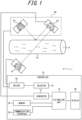
- FIG. 1 is a block diagram illustrating an example of a schematic structure of a fluid measurement apparatus according to an embodiment.
- a power source that supplies power to each functional unit, a structure of supplying power from the power source to each functional unit, and the like are not illustrated in the drawing.
- Functional units illustrated in FIG. 1 may be included in or omitted from a fluid measurement apparatus 1 according to an embodiment as appropriate.
- the fluid measurement apparatus can measure a flow state (e.g. flow velocity or flow amount) of a flowing object (fluid). Specifically, the fluid measurement apparatus can calculate the flow amount or flow velocity of the fluid as the flow state of the fluid.
- the flow amount is the volume or mass of the fluid flowing per unit time, and the flow velocity is the distance the fluid travels per unit time.
- the fluid measurement apparatus can calculate the flow state of the fluid using the Doppler effect of light.
- Light applied to an irradiated object (the fluid, a flow channel in which the fluid flows, and the like) is scattered by the fluid, and its frequency is shifted (Doppler-shifted) due to the Doppler effect depending on the flow state of the fluid.
- the Doppler effect can be used to calculate the flow state.
- the fluid measurement apparatus can emit light from an optical emitter toward the irradiated object including the fluid to be measured, and receive, by an optical detector, interference light including light scattered by the irradiated object. The fluid measurement apparatus can then calculate the flow state of the fluid based on the output of the optical detector.
- the fluid to be measured is not limited, as long as it has translucency and its flow state can be calculated using the Doppler effect of light.
- the fluid is any fluid that scatters light by itself or contains a substance (scattering substance) that scatters light.
- the fluid include liquids such as water, blood, milk, printer ink, and oil, and gases containing solids such as a powder. At least part of the fluid has translucency.
- the fluid measurement apparatus may regard the flow amount or flow velocity of the scattering substance, the powder, or the like as the flow amount or velocity of the fluid. That is, the "flow amount or flow velocity of the fluid" can be interpreted as the "flow amount or flow velocity of the scattering substance, the powder, or the like".
- the fluid measurement apparatus 1 includes an estimation unit 16 that estimates the flow state based on received light.
- the fluid measurement apparatus 1 may also include, for example, at least one of a sensor 60 and a first optical emitter 61.
- the first optical emitter 61 can emit light such as laser light toward a flow channel 70.
- the sensor 60 can perform detection relating to a fluid A flowing in the flow channel 70.
- the estimation unit 16 can estimate the flow state of the fluid A flowing in the flow channel 70, based on the result of detection by the sensor 60.
- the first optical emitter 61 is positioned with respect to the flow channel 70 so that light can be emitted toward the fluid A flowing in the flow channel 70.
- the sensor 60 is positioned with respect to the flow channel 70 so that the flow state of the fluid A flowing in the flow channel 70 can be estimated.
- the sensor 60 includes a second optical emitter 62 and an optical detector 64.
- the first optical emitter 61, the second optical emitter 62, the optical detector 64, and the flow channel 70 are positioned as appropriate so as to satisfy the following conditions:
- the first optical emitter 61 and the second optical emitter 62 may each be composed of, for example, any number of laser diodes (LDs).
- the first optical emitter 61 and the second optical emitter 62 can emit light toward the flow channel 70.
- the first optical emitter 61 and the second optical emitter 62 can emit laser light or the like.
- the first optical emitter 61 and the second optical emitter 62 may each be any optical emitter capable of emitting light of a wavelength with which the measured object contained in the fluid A is detectable.
- a driver 50 can drive the first optical emitter 61, the second optical emitter 62, and the optical detector 64.
- the driver 50 may be composed of, for example, any laser drive circuit.
- the driver 50 may be included in the fluid measurement apparatus 1, or provided outside the fluid measurement apparatus 1.
- the driver 50 may be included in the sensor 60, or provided outside the sensor 60.
- the optical detector 64 may be composed of, for example, any number of photodiodes (PDs).
- the optical detector 64 can receive at least part of at least one of light emitted from the first optical emitter 61 and light emitted from the second optical emitter 62.
- the optical detector 64 can receive light (transmitted light) transmitted through the fluid A in the flow channel 70 from among the light emitted from the first optical emitter 61 toward the flow channel 70. That is, the optical detector 64 can receive light (forward scattered light) scattered forward by the fluid A.
- the optical detector 64 can also receive light (reflected light) reflected by the flow channel 70 from among the light emitted from the second optical emitter 62 toward the flow channel 70.
- a signal relating to the intensity of light (received light) received by the optical detector 64 is transmitted to a generator 12.
- the generator 12 will be described later.
- the fluid measurement apparatus 1 may use any type of amplifier and/or filter (not illustrated) when transmitting the signal relating to the intensity of the received light to the generator 12 and processing it.
- the flow channel 70 in which the fluid A flows may be a tubular member made of any type of material.
- the flow channel 70 may be configured to prevent the fluid A from leaking so that the flow state of the fluid A can be measured appropriately.
- the flow channel 70 may be a tube made of plastic, vinyl chloride, glass, or the like.
- the flow channel 70 may be a tissue forming a flow channel through which a body fluid of a human, an animal, or the like flows, such as a blood vessel.
- the flow channel 70 may be made of a material that transmits at least part of light emitted from the first optical emitter 61 and/or light emitted from the second optical emitter 62.
- the shape of the flow channel 70 is not limited, as long as it allows the fluid A to flow.
- the shape of the flow channel 70 may be, for example, any of a circle, a rectangle, and other polygons.
- FIG. 1 schematically illustrates a state in which the fluid A flows in the flow channel 70.
- the fluid A contains particles or fine particles
- the particles or fine particles contained in the fluid A move with the flow of the fluid A.
- the first optical emitter 61 is positioned with respect to the flow channel 70 and/or the sensor 60 so that the flow state of the fluid A flowing in the flow channel 70 can be appropriately measured by the sensor 60. Specifically, the first optical emitter 61 is positioned so that light can be appropriately emitted to the fluid A flowing in the flow channel 70. The first optical emitter 61 is also positioned with respect to the flow channel 70 and/or the optical detector 64 so that light emitted from the first optical emitter 61 and transmitted through the flow channel 70 and the fluid A can be appropriately received by the optical detector 64.
- the first optical emitter 61 and the second optical emitter 62 are arranged on opposite sides of the flow channel 70, in a planar view in a direction in which the fluid A flows in the flow channel 70. That is, the first optical emitter 61 and the second optical emitter 62 are arranged on opposite sides with the flow channel 70 therebetween. This allows the optical detector 64 to receive both transmitted light and reflected light.
- the second optical emitter 62 and/or the optical detector 64 are positioned with respect to the flow channel 70 so that the flow state of the fluid A flowing in the flow channel 70 can be measured appropriately.
- the second optical emitter 62 is positioned so that light can be appropriately emitted to the flow channel 70.
- the optical detector 64 is positioned so that light emitted from the second optical emitter 62 and reflected by the flow channel 70 can be received appropriately.
- the second optical emitter 62 and the optical detector 64 may be provided separately.
- the first optical emitter 61 may be a part of a sensor of one package including the optical detector.
- the fluid measurement apparatus 1 will be described in more detail below.
- the fluid measurement apparatus 1 includes a controller 10 that controls the whole apparatus.
- the controller 10 includes the generator 12 and the estimation unit 16.
- the controller 10 may also include an adjustor 18.
- the controller 10 may also include at least one of a memory 20, a communication interface 30, a display 40, and the driver 50 as appropriate.
- the controller 10 includes at least one processor such as a central processing unit (CPU), to provide control and processing capacity for achieving various functions of the generator 12, the estimation unit 16, the adjustor 18, and the like.
- the controller 10 may implement the functions of the generator 12, the estimation unit 16, the adjustor 18, and the like by one processor, by several processors, or by respective separate processors.
- Each processor may be implemented as a single integrated circuit.
- Each processor may be implemented as a plurality of integrated circuits and/or discrete circuits communicably connected to one another.
- Each processor may be implemented based on any of various conventionally known techniques.
- the functions of the generator 12, the estimation unit 16, and the adjustor 18 may be implemented, for example, by a CPU and a program executed by the CPU.
- the generator 12 generates a frequency spectrum S according to an embodiment.
- the generation of the frequency spectrum S by the generator 12 will be described in detail later.
- the estimation unit 16 can estimate the flow state of the fluid A based on the frequency spectrum S.
- the estimation of the flow state of the fluid A by the estimation unit 16 will be described in detail later.
- the adjustor 18 can adjust the light quantity of light received by the optical detector 64, by adjusting, for example, the intensity of light emitted from the first optical emitter 61 and received by the optical detector 64 and/or the intensity of light emitted from the second optical emitter 62 and received by the optical detector 64.
- the adjustment of the light quantity by the adjustor 18 will be described in detail later.
- the "light quantity” herein refers to the quantity of light received by the optical detector 64, and indicates the amount of light energy.
- the memory 20 may include semiconductor memory, magnetic memory, etc.
- the memory 20 may store various information, programs to be executed, and the like.
- the memory 20 may function, for example, as working memory of the generator 12 and/or the estimation unit 16.
- the memory 20 may store various information used to estimate the flow state of the fluid A from the frequency spectrum S generated by the generator 12.
- the memory 20 may store the foregoing various information beforehand, or acquire the information through external communication or the like and store them.
- the memory 20 may store the foregoing various information as any of various memory cards.
- the memory 20 may be included in, for example, the generator 12 and/or the estimation unit 16.
- the communication interface 30 can achieve various functions such as wireless communication.
- the communication interface 30 may achieve communication by any of various communication systems such as Long Term Evolution (LTE).
- LTE Long Term Evolution
- the communication interface 30 may include a modem with a communication system standardized in the International Telecommunication Union Telecommunication Standardization Sector (ITU-T), for example.
- ITU-T International Telecommunication Union Telecommunication Standardization Sector
- the communication interface 30 may, for example, wirelessly communicate with an external apparatus such as an external server or a cloud server via a network, through an antenna.
- the communication interface 30 may receive the foregoing various information from an external database such as an external server or a cloud server. Such information received by the communication interface 30 may be stored in the memory 20.
- the display 40 can provide information such as the flow state of the fluid A to a user as video, by displaying the measurement result of the flow state of the fluid A or the like on a display device such as a liquid crystal display (LCD), an organic EL display, or an inorganic EL display.
- a display device such as a liquid crystal display (LCD), an organic EL display, or an inorganic EL display.
- the display 40 may display images of characters, figures, signs, graphs, and the like on the display device.
- the display 40 may display images of objects for operation and the like on the display device.
- the form of information presented by the display 40 is not limited to a form that has visual effect on the user.
- the display 40 may output information such as the flow state of the fluid A from an audio device such as a speaker as sound.
- the display 40 may provide information such as the measurement result to the user as sound and video, using the audio device and the display device.
- the display 40 may have any structure that can notify the user of the flow state of the fluid A.
- the memory 20, the communication interface 30, the display 40, and the driver 50 may each be included in the fluid measurement apparatus 1 or provided outside the fluid measurement apparatus 1.
- the display device may be included in the sensor 60 or provided outside the sensor 60.
- FIG. 2 is a diagram for explaining detection of scattered light in fluid measurement according to an embodiment.
- the first optical emitter 61, the second optical emitter 62 and the optical detector 64 in the sensor 60, and the flow channel 70 in which the fluid A flows are enlarged in the drawing.
- FIG. 2 schematically illustrates a state in which the fluid A flows in the right direction at a velocity V in the flow channel 70. In the case where the fluid A contains fine particles, the fine particles flow at the velocity V in the flow channel 70, too.
- Light emitted from the first optical emitter 61 toward the flow channel 70 includes incident light Le1.
- the incident light Le1 is light of a frequency f0 when emitted from the first optical emitter 61.
- the incident light Le1 of the frequency f0 is denoted by Le1(f0).
- Light emitted from the second optical emitter 62 toward the flow channel 70 includes incident light Le2.
- the incident light Le2 is light of the frequency f0 when emitted from the second optical emitter 62.
- the incident light Le2 of the frequency f0 is denoted by Le2(f0).
- the incident light Le2 is reflected by the flow channel 70. That is, the incident light Le2 is not scattered by the fluid A but scattered by the flow channel 70 to become scattered light Lr2.
- the scattered light Lr2 results from scattering of the incident light Le2 by the stationary flow channel 70.
- the frequency f0 of the incident light Le2 is unchanged.
- the scattered light Lr2 of the frequency f0 is denoted by Lr2(f0).
- second light Lr2 light not shifted in frequency from among light emitted from the second optical emitter 62 and received by the optical detector 64.
- At least part of the incident light Le1 is not reflected by the flow channel 70 but transmitted through the flow channel 70. That is, at least part of the incident light Le1 is not scattered by the flow channel 70 but scattered by the fluid A to become scattered light Lr1.
- the frequency of the scattered light Lr1 is Doppler-shifted depending on the moving velocity of the fluid A, and as a result slightly changes from f0.
- the scattered light Lr1 whose frequency has changed from f0 by ⁇ f is denoted by Lr1(f0 + ⁇ f).
- light shifted in frequency as a result of being transmitted through the fluid A flowing in the flow channel 70 from among light emitted from the first optical emitter 61 and received by the optical detector 64 is also referred to as "first light Lr1".
- the fluid measurement apparatus 1 can estimate the flow state of the fluid A, based on output from the optical detector 64 that has received the scattered light Lr1 and the scattered light Lr2.
- Fluid measurement by the fluid measurement apparatus 1 will be described below.
- FIG. 3 is a flowchart illustrating fluid measurement according to an embodiment.
- the generator 12 acquires a beat signal of interference light produced as a result of interference between scattered light (second light) Lr2 from the stationary flow channel 70 and scattered light (first light) Lr1 from the moving fluid A, based on output from the optical detector 64 (step S1).
- the beat signal indicates the relationship between the intensity of signal output from the optical detector 64 and time.
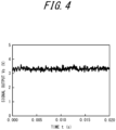
- FIG. 4 is a diagram illustrating an example of the beat signal acquired in step S1 in FIG. 3 .
- the vertical axis represents the intensity of signal output
- the horizontal axis represents time.
- the signal output from the optical detector 64 is voltage value, and is expressed in voltage unit (V) as signal output Vs.
- the beat signal is not limited to voltage, as long as it indicates temporal changes in the intensity of signal output.
- the beat signal may be current value or resistance value.
- the generator 12 After the beat signal is acquired in step S1, the generator 12 generates a frequency spectrum S from the acquired beat signal (step S2).
- the frequency spectrum S is a spectrum indicating signal intensity for each frequency component, and is generated based on the beat signal at a predetermined time.
- the generator 12 can generate the frequency spectrum S at the predetermined time by performing a fast Fourier transform (FFT) on the beat signal at the predetermined time acquired in step S1.
- FFT fast Fourier transform
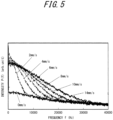
- FIG. 5 is a diagram illustrating an example of the frequency spectrum S generated in step S2 in FIG. 3 .
- the frequency spectrum S represents the relationship between the intensity of signal output of the optical detector 64 at a predetermined time and frequency.
- the vertical axis represents intensity P(f) of signal output in arbitrary units
- the horizontal axis represents frequency f.
- the frequency spectrum S is a spectrum (frequency spectrum) representing power at the predetermined time as a function of frequency based on the beat signal.
- the Doppler shift frequency depends on the velocity of the fluid A.
- FIG. 5 illustrates respective frequency spectra S generated from several beat signals acquired by changing the flow velocity of the fluid A.
- respective frequency spectra S in the cases where the flow velocity of the fluid A is 2 mm/s, 4 mm/s, 6 mm/s, 8 mm/s, 10 mm/s, and 14 mm/s are illustrated together, as an example.
- respective frequency spectra S at a predetermined time can be generated. That is, each of the plurality of frequency spectra S illustrated in FIG. 5 is an instantaneous frequency spectrum at a predetermined time.
- the frequency spectrum S depends on the flow state. Accordingly, the fluid measurement apparatus 1 can measure the flow state based on the frequency spectrum S.
- the frequency spectrum generated by performing an FFT on the beat signal as mentioned above is hereafter also referred to as "frequency spectrum P(f)".
- step S3 the estimation unit 16 performs frequency weighting on the generated frequency spectrum P(f) according to the following Formula (1) (step S3): ⁇ ⁇ P ⁇
- step S3 the estimation unit 16 integrates the Formula (1) in an adequate frequency range to calculate an integral value expressed by the following Formula (2) (step S4): ⁇ ⁇ ⁇ P ⁇ d ⁇
- the estimation unit 16 multiplies the integral value expressed by the Formula (2) by a proportionality constant K.
- the estimation unit 16 can then calculate the following value, by normalizing the resultant value by dividing it by the total power (the square of I), i.e. a DC component, of the received light signal so as not to depend on the light reception intensity of light such as laser light (Formula (3)): K ⁇ ⁇ ⁇ P ⁇ d ⁇ I 2 ⁇
- the estimation unit 16 can then estimate the flow state of the fluid A to be measured, by comparing the value of the Formula (3) calculated for the fluid to be measured and the value of the Formula (3) calculated for the fluid in a known flow state measured beforehand (step S5).
- FIG. 6 is a diagram illustrating an example of the flow amount of the fluid calculated as described above.
- the flow amount can be measured from the frequency spectrum P(f) generated from the beat signal at each given time.
- FIG. 6 is a diagram in which an example of temporal changes in the measured flow amount is plotted.
- FIG. 6 illustrates temporal changes in the flow amount of the fluid that is blood, i.e. the blood flow amount, as an example.
- the vertical axis represents the flow amount of blood (blood flow amount), and the horizontal axis represents time.
- the blood flow amount in the vertical axis is in arbitrary units.
- the fluid measurement apparatus 1 can also estimate information such as the flow velocity of the fluid A, based on information such as the cross-sectional area of the flow channel 70.
- the fluid measurement apparatus 1 can calculate the flow amount of the fluid or the like from the frequency spectrum P(f) generated from the beat signal.
- the fluid measurement apparatus 1 includes the estimation unit 16.
- the estimation unit 16 can estimate the flow state of the fluid A.
- the estimation unit 16 can estimate the flow state of the fluid A based on the first light Lr1 shifted in frequency.
- the estimation unit 16 estimates the flow state of the fluid A based on the difference between the frequency of the first light Lr1 and the frequency of the second light Lr2.
- the optical detector 64 may receive scattered light that is light emitted from the second optical emitter 62 and scattered by the flow channel 70, and the first light Lr1.
- the estimation unit 16 may then estimate the flow state of the fluid A, based on the difference between the frequency of the scattered light emitted from the second optical emitter 62 and scattered by the flow channel 70 and the frequency of the first light Lr1.
- the flow state (e.g. flow velocity or flow amount) of the fluid can be measured appropriately and accurately under various conditions.
- the fluid measurement apparatus 1 according to an embodiment even in the case where the fluid A is a colorless and transparent liquid such as water, the flow state (e.g. flow velocity or flow amount) can be measured appropriately and accurately.
- the fluid measurement apparatus 1 according to an embodiment therefore offers high convenience.
- a flowmeter that uses the principle of Doppler shift calculates the flow amount of a fluid, for example, through arithmetic operations using primary moment for a spectrum obtained as a result of FFT analysis of a Doppler phenomenon caused by an object irradiated with laser light.
- a laser Doppler flowmetry (LDF) method is conventionally known as a method of measuring blood flow using laser light.
- the fluid measurement apparatus 1 can calculate the flow amount of blood or the like by the LDF method using only one optical emitter (second optical emitter 62) and one optical detector (optical detector 64).
- a transparent liquid such as water does not cause favorable backward scattering of laser light. It is therefore conventionally difficult to favorably estimate the flow state of a fluid such as a transparent liquid in some cases. The following will examine the measurement of the flow amount of a transparent liquid such as water.
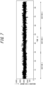
- FIG. 7 is a diagram illustrating an example of measuring the flow amount of a transparent liquid such as water based on a conventional technique.
- the measurement illustrated in FIG. 7 can be regarded as an example of calculating the flow amount of the transparent liquid using only the sensor 60 (i.e. without using the first optical emitter 61) in the fluid measurement apparatus 1 according to an embodiment. This result is equally obtained in the case of performing measurement by the conventional LDF method using the same structure.
- a transparent liquid such as water flows in a flow channel of 2 mm in diameter, as an example.
- the fluid in a flow amount known beforehand is caused to flow using, for example, a pump capable of causing the fluid to flow in a set flow amount. That is, in the example illustrated in FIG. 7 , a known flow amount is actually measured to determine measurement accuracy.
- the horizontal axis represents elapsed time (sec), and the vertical axis represents the flow amount measured (arbitrary units).
- the flow amount of the fluid is changed among sections 1, 2, and 3. Specifically, in the section 1, the fluid flows in a flow amount of 0 ml/min (i.e. the fluid is (approximately) stationary). In the section 2, the fluid flows in a flow amount of 3 ml/min. In the section 3, the fluid flows in a flow amount of 6 ml/min. However, despite the flow amount of the fluid being actually changed for each section, such change for each section is not observed in the measured flow amount, as illustrated in FIG. 7 .
- the example illustrated in FIG. 7 can be supposed as an example of measuring the fluid using only the sensor 60 (i.e. without using the first optical emitter 61) in the fluid measurement apparatus 1 illustrated in FIG. 1 , as mentioned above. At least part of light emitted from the second optical emitter in the sensor 60 is interfacially reflected by the flow channel 70 and then received by the optical detector 64. Light not interfacially reflected by the flow channel 70 from among the light emitted from the second optical emitter in the sensor 60 toward the flow channel 70 is transmitted through the fluid A. In this case, since the fluid A is transparent, the light is hardly scattered backward by the fluid A flowing in the flow channel 70.
- the optical detector 64 can hardly receive backward scattered light by the fluid A from among the light emitted from the second optical emitter. This is considered to be the reason why, despite the flow amount of the fluid being actually changed for each section, such change for each section is not observed in the measured flow amount, as can be seen in the example illustrated in FIG. 7 .
- the optical detector 64 can receive not only light emitted from the second optical emitter 62 but also light emitted from the first optical emitter 61, as illustrated in FIGS. 1 and 2 .
- the optical detector 64 can receive at least part (scattered light Lr2) of light scattered by the flow channel 70 from among light (incident light Le2) emitted from the second optical emitter 62 toward the flow channel 70.
- the optical detector 64 can also receive at least part (scattered light Lr1) of light transmitted through the fluid A flowing in the flow channel 70 from among light (incident light Le1) emitted from the first optical emitter 61 toward the flow channel 70.
- the scattered light Le1 is light (first light Lr1) shifted in frequency as a result of being transmitted through the fluid A flowing in the flow channel 70 from among light emitted from the first optical emitter 61 and received by the optical detector 64, as mentioned above.
- the scattered light Lr2 is light (second light Lr2) not shifted in frequency from among light emitted from the second optical emitter 62 and received by the optical detector 64, as mentioned above.
- the estimation unit 16 can estimate the flow state of the fluid Abased on the first light Lr1.
- the estimation unit 16 may estimate the flow state of the fluid A based on the difference between the frequency of the first light Lr1 and the frequency of the second light Lr2. Specifically, the estimation unit 16 may estimate the flow state of the fluid A based on the difference between the frequency of the scattered light scattered by the flow channel 70 from among the light emitted from the second optical emitter 62 and the frequency of the first light Lr1.
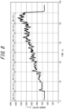
- FIG. 8 is a diagram illustrating an example of measuring a fluid that is a transparent liquid such as water in the fluid measurement apparatus 1 illustrated in FIGS. 1 and 2 .
- FIG. 8 illustrates an example of measuring a fluid that is a transparent liquid in a state in which not only the sensor 60 but also the first optical emitter 61 is appropriately operated in the fluid measurement apparatus 1 according to an embodiment.
- the horizontal axis represents elapsed time (sec)
- the vertical axis represents the flow amount measured (arbitrary units).
- the fluid in a flow amount known beforehand is caused to flow using, for example, a pump capable of causing the fluid to flow in a set flow amount. That is, in the example illustrated in FIG. 8 , too, a known flow amount is actually measured to determine measurement accuracy.
- the flow amount in the vertical axis is indicated as sensor output.
- the “sensor output” may be, for example, the intensity of light received by the optical detector 64 in the sensor 60 in the fluid measurement apparatus 1 according to an embodiment.
- the intensity of light received by the optical detector 64 for example, voltage value may be detected as signal output from the optical detector 64.
- the signal output is, however, not limited to voltage as long as it indicates temporal changes in the intensity of signal output, and may be current value, resistance value, or the like.
- sections of 10 sec are set from the measurement start, and the flow amount of the fluid is changed for each section.
- the fluid flows in a flow amount of 0 ml/min (i.e. the fluid is (approximately) stationary).
- the fluid flows in a flow amount of 1 ml/min.
- the fluid flows in a flow amount of 2 ml/min.
- the fluid flows in a flow amount of 3 ml/min. The flow amount is equally increased gradually in subsequent sections.
- the sensor output increases with the gradually increased flow amount.
- the optical detector 64 can receive light reflected by the flow channel 70, as the second light Lr2.
- the optical detector 64 can also receive light Doppler-shifted as a result of being transmitted through the fluid that is a transparent liquid such as water, as the first light Lr1.
- the fluid measurement apparatus 1 according to an embodiment can acquire a beat based on interference between the second light Lr2 and the first light Lr1.
- the fluid measurement apparatus 1 according to an embodiment can measure even a fluid that is a transparent liquid such as water.
- the flow state e.g. flow velocity or flow amount
- the fluid measurement apparatus 1 according to an embodiment therefore offers high convenience.
- the balance between the light quantity of light output from the first optical emitter 61 and the light quantity of light output from the second optical emitter 62 is important. Adjustment of the balance between the light quantity of light output from the first optical emitter 61 and the light quantity of light output from the second optical emitter 62 in the fluid measurement apparatus 1 according to an embodiment will be described below.
- the fluid measurement apparatus 1 in the case where the output based on the first light Lr1 and the output based on the second light Lr2 from among the signal output of the optical detector 64 based on the received light are not balanced, it may be difficult to favorably detect the beat formed by the first light Lr1 and the second light Lr2. If the beat formed by the first light Lr1 and the second light Lr2 cannot be favorably detected, the fluid measurement apparatus 1 according to an embodiment is likely to have difficulty in measuring the flow amount of a transparent liquid or the like with favorable accuracy.
- the balance between the output based on light emitted from the first optical emitter 61 and the output based on light emitted from the second optical emitter 62 from among the signal output of the optical detector 64 may be adjustable.
- the adjustor 18 may be capable of adjusting the light quantity of light received by the optical detector 64. This improves the usefulness of the fluid measurement apparatus 1 because the signal output of the optical detector 64 can be adjusted to enable detection of the difference between the frequency of the first light Lr1 and the frequency of the second light Lr2.
- Such light quantity adjustment in the fluid measurement apparatus 1 according to an embodiment can be performed in various ways. Some typical examples will be described below.
- the adjustor 18 may adjust the light quantity of light emitted from at least one of the first optical emitter 61 and the second optical emitter 62, through the driver 50. That is, the adjustor 18 can adjust the light quantity of received light by increasing or decreasing the light quantity of light emitted from the first optical emitter 61 and/or the second optical emitter 62.
- the adjustor 18 may adjust the power supplied from the driver 50 to the first optical emitter 61 and/or the second optical emitter 62.
- the adjustor 18 may adjust the current or voltage supplied from the driver 50 to the first optical emitter 61 and/or the second optical emitter 62.
- an electrically-operated or manually-operated slit or the like may be provided in the first optical emitter 61 and/or the second optical emitter 62, to enable adjustment of the light quantity of light emitted from the first optical emitter 61 and/or the second optical emitter 62.
- the adjustor 18 may adjust the state of the slit or the like provided in the first optical emitter 61 and/or the second optical emitter 62, for example through the driver 50.
- the adjustor 18 may adjust the light reception sensitivity of the optical detector 64.
- any filter may be provided in the first optical emitter 61 and/or the second optical emitter 62.
- a displacement mechanism that can be driven by a motor or the like may be provided in at least one of the first optical emitter 61, the second optical emitter 62, the optical detector 64, and the flow channel 70, to enable adjustment of its position. This can change the light quantity of light received by the optical detector 64.
- the fluid measurement apparatus 1 can thus adjust the light quantity of received light to enable detection of the difference between the frequency of the first light Lr1 and the frequency of the second light Lr2.
- FIG. 9 is a diagram illustrating the adjustor 18 capable of adjusting the position of at least one of the first optical emitter 61, the second optical emitter 62, the optical detector 64, and the flow channel 70 in the fluid measurement apparatus 1 according to an embodiment.
- control lines connecting the adjustor 18 to the first optical emitter 61, the sensor 60 (second optical emitter 62 and optical detector 64), and the flow channel 70 are indicated by dashed lines.
- a displacement mechanism that can be driven by a motor or the like is provided in at least one of the first optical emitter 61, the second optical emitter 62, the optical detector 64, and the flow channel 70 connected to the adjustor 18 by a control line in FIG. 9 .
- the adjustor 18 is connected to at least one of the first optical emitter 61, the second optical emitter 62, the optical detector 64, and the flow channel 70 by a control line, to drive the displacement mechanism provided in the at least one of the first optical emitter 61, the second optical emitter 62, the optical detector 64, and the flow channel 70.
- the adjustor 18 may adjust the position of at least one of the first optical emitter 61, the second optical emitter 62, the optical detector 64, and the flow channel 70 in the fluid measurement apparatus 1 according to an embodiment.
- the adjustor 18 may adjust the distance between the optical detector 64 and the first optical emitter 61 and/or the second optical emitter 62, to adjust the light quantity of light emitted from the first optical emitter 61 and/or the second optical emitter 62 and received by the optical detector 64.
- the adjustor 18 may adjust the position of at least one of the first optical emitter 61, the second optical emitter 62, and the optical detector 64 relative to the flow channel 70.
- the displacement mechanism is not limited to an electrically-operated mechanism.
- at least one of the first optical emitter 61, the second optical emitter 62, the optical detector 64, and the flow channel 70 may be provided with a displacement mechanism capable of manually changing position.
- the user can adjust the light quantity of received light by, for example, adjusting the position while checking the measurement result displayed on the display device. This improves the usefulness of the fluid measurement apparatus 1 while reducing power consumption.
- a rotation mechanism that can be driven by a motor or the like may be provided in at least one of the first optical emitter 61, the second optical emitter 62, the optical detector 64, and the flow channel 70, to enable adjustment of its orientation (angle). This can change the light quantity of received light.
- the fluid measurement apparatus 1 can thus adjust the light quantity of received light to enable detection of the difference between the frequency of the first light Lr1 and the frequency of the second light Lr2.
- the rotation mechanism is any mechanism that realizes at least part of rotation motion.
- the rotation mechanism need not necessarily realize rotation motion of one turn, and may realize, for example, rotation motion of a half turn or a 1/4 turn. Rotation is not limited to one direction. That is, the rotation mechanism may realize rotation motion of 360 degrees.
- FIG. 9 is a diagram illustrating the adjustor 18 capable of adjusting the orientation (angle) of at least one of the first optical emitter 61, the second optical emitter 62, the optical detector 64, and the flow channel 70 in the fluid measurement apparatus 1 according to an embodiment.
- control lines connecting the adjustor 18 to the first optical emitter 61, the sensor 60 (second optical emitter 62 and optical detector 64), and the flow channel 70 are indicated by dashed lines.
- a rotation mechanism that can be driven by a motor or the like is provided in at least one of the first optical emitter 61, the second optical emitter 62, the optical detector 64, and the flow channel 70 connected to the adjustor 18 by a control line in FIG. 9 .
- the adjustor 18 is connected to at least one of the first optical emitter 61, the second optical emitter 62, the optical detector 64, and the flow channel 70 by a control line, to drive the rotation mechanism provided in the at least one of the first optical emitter 61, the second optical emitter 62, the optical detector 64, and the flow channel 70.
- the adjustor 18 may adjust the orientation (angle) of at least one of the first optical emitter 61, the second optical emitter 62, the optical detector 64, and the flow channel 70 in the fluid measurement apparatus 1 according to an embodiment.
- the adjustor 18 can change the solid angle of light incident from one direction.
- the solid angle of light received by the light receiving surface of the optical detector 64 is at its maximum. In this case, the quantity of light received by the light receiving surface of the optical detector 64 is expected to be near maximum.
- the solid angle of light received by the light receiving surface of the optical detector 64 is smaller.
- the solid angle of light received by the light receiving surface of the optical detector 64 is smaller if light is incident on the light receiving surface of the optical detector 64 from an oblique direction.
- the solid angle of light received by the light receiving surface of the optical detector 64 can be decreased with an increase of the incidence angle of light on the light receiving surface of the optical detector 64. Consequently, the light quantity of received light can be decreased.
- the adjustor 18 may adjust the incidence angle (incidence angle 1) of light emitted from the first optical emitter 61 and received by the optical detector 64 with respect to the optical detector 64. Moreover, in an embodiment, the adjustor 18 may adjust the incidence angle (incidence angle 2) of light emitted from the second optical emitter 62 and received by the optical detector 64 with respect to the optical detector 64. The adjustor 18 may adjust at least one of the incidence angle 1 and the incidence angle 2.
- the rotation mechanism is not limited to an electrically-operated mechanism.
- at least one of the first optical emitter 61, the second optical emitter 62, the optical detector 64, and the flow channel 70 may be provided with a rotation mechanism capable of manually changing orientation (angle).
- the adjustor 18 may adjust the light quantity of light emitted from at least one of the first optical emitter 61 and the second optical emitter 62 and received by the optical detector 64, to enable detection of the difference between the frequency of the first light Lr1 and the frequency of the second light Lr2.
- the optical detector 64 may be unable to favorably detect the flow state of the fluid A when the fluid A flows in the flow channel 70.
- the Doppler shift when the light emitted from the first optical emitter 61 is transmitted through the fluid A is likely to be small.
- the Doppler shift cannot be detected with sufficient sensitivity, depending on the structures of the first optical emitter 61 and the optical detector 64.
- the fluid measurement apparatus 1 may have an arrangement wherein the direction in which the fluid A flows in the flow channel 70 and the direction in which the first optical emitter 61 emits light are not orthogonal to each other.
- the first optical emitter 61 may emit light having a component in a direction parallel to the flow direction of the fluid A.
- the "direction parallel to the flow direction of the fluid A" with regard to the light emitted from the first optical emitter 61 is not limited to the same direction as the direction in which the fluid A flows, and may be the opposite direction from the direction in which the fluid A flows.
- the Doppler shift when light emitted from the first optical emitter 61 is transmitted through the fluid A can be increased.
- the first optical emitter 61 and/or the flow channel 70 may be provided with an appropriate displacement mechanism and/or a rotation mechanism, as mentioned above.
- the displacement mechanism and/or the rotation mechanism may be automatically operated or manually operated.
- the signal output of the optical detector 64 may be adjusted using, for example, the displacement mechanism and/or the rotation mechanism provided in the optical detector 64 and/or the flow channel 70.
- the signal output of the optical detector 64 may be adjusted using, for example, the displacement mechanism and/or the rotation mechanism provided in the optical detector 64 and/or the flow channel 70.
- at least one of the light emission intensity, position, and orientation (angle) of the first optical emitter 61 may be adjusted depending on the changed direction of the first optical emitter 61.
- at least one of the light reception sensitivity, position, and orientation (angle) of the optical detector 64 may be adjusted depending on the changed direction of the first optical emitter 61.
- the adjustor 18 may adjust at least one of the incidence angle of light emitted from the first optical emitter 61 with respect to the flow channel 70 and the incidence angle of light emitted from the second optical emitter 62 with respect to the flow channel 70.
- the structure of the first optical emitter 61, the second optical emitter 62, and the optical detector 64 is not limited to the example illustrated in FIGS. 1 and 9 , and may be any of various structures.
- the first optical emitter 61, the second optical emitter 62, and the optical detector 64 may each be provided separately.
- the first optical emitter 61, the second optical emitter 62, and the optical detector 64 may all be included in a sensor in one package.
- a reflector may be installed in at least part of the flow channel or outside the flow channel so as to reflect transmitted light.
- Such a fluid measurement apparatus 1 can receive reflected light of transmitted light and measure the flow amount. In this case, the optical path length of received light increases, with it being possible to achieve more suitable measurement.
- the fluid measurement apparatus 1 need not necessarily include two different optical emitters, i.e. the first optical emitter 61 and the second optical emitter 62. In other words, a simpler sensor structure may be used.
- two sensors in each of which an optical emitter and an optical detector are included in one package may be used to ease measurement by the fluid measurement apparatus 1 according to an embodiment, as illustrated in FIG. 10 .
- a first sensor 60A includes the first optical emitter 61 and a first optical detector 63
- a second sensor 60B includes the second optical emitter 62 and second optical detector 64.
- the first optical detector 63 in the first sensor 60A receives at least part of light emitted from the first optical emitter 61 and scattered by the flow channel 70.
- the first optical detector 63 also receives at least part of light emitted from the second optical emitter 62 and transmitted through the fluid A flowing in the flow channel 70.
- the fluid A is a transparent liquid such as water
- the flow state can be measured appropriately and accurately.
- a highly convenient fluid measurement apparatus can therefore be provided.
- simply by preparing two sensors each of which includes an optical emitter and an optical detector and arranging them to face each other in a staggered configuration the sensors in the fluid measurement apparatus 1 according to an embodiment can be configured easily.
- the foregoing embodiments are not limited to embodiments as the fluid measurement apparatus 1.
- the foregoing embodiments may be carried out as a fluid measurement method performed in the fluid measurement apparatus 1 or a program executed by a computer that controls an apparatus such as the fluid measurement apparatus 1.
- a fluid measurement method comprises: emitting light to an irradiated object that includes a fluid; receiving first received light transmitted through the fluid to thereby be shifted in frequency; and estimating a flow state of the fluid; receiving second received light emitted to the irradiated object and not shifted in frequency, wherein the flow state of the fluid is estimated based on a difference between a frequency of the first received light and a frequency of the second received light, wherein the irradiated object includes a flow channel in which the fluid flows, wherein the first received light is emitted by a first optical emitter, wherein the second received light is emitted by a second optical emitter, and wherein the second optical emitter is located on an opposite side of the flow channel from the first optical emitter, in a planar view in a direction in which the fluid flows in the flow channel.
- a program causes a computer to execute: emitting light from a first optical emitter to an irradiated object that includes a fluid; receiving, by an optical detector, first received light emitted from the first optical emitter and transmitted through the fluid to thereby be shifted in frequency; emitting light from a second optical emitter to the irradiated object; receiving, by the optical detector, second received light emitted from the second optical emitter and not shifted in frequency; and estimating, by an estimation unit, a flow state of the fluid based on a difference between a frequency of the first received light and a frequency of the second received light, wherein the irradiated object includes a flow channel in which the fluid flows, and wherein the second optical emitter is located on an opposite side of the flow channel from the first optical emitter, in a planar view in a direction in which the fluid flows in the flow channel.
Landscapes
- Physics & Mathematics (AREA)
- Health & Medical Sciences (AREA)
- General Physics & Mathematics (AREA)
- Fluid Mechanics (AREA)
- Electromagnetism (AREA)
- Life Sciences & Earth Sciences (AREA)
- Engineering & Computer Science (AREA)
- Biophysics (AREA)
- Public Health (AREA)
- Biomedical Technology (AREA)
- Heart & Thoracic Surgery (AREA)
- Medical Informatics (AREA)
- Molecular Biology (AREA)
- Surgery (AREA)
- Animal Behavior & Ethology (AREA)
- General Health & Medical Sciences (AREA)
- Pathology (AREA)
- Veterinary Medicine (AREA)
- Physiology (AREA)
- Cardiology (AREA)
- Hematology (AREA)
- Measuring Volume Flow (AREA)
- Multimedia (AREA)
- Aviation & Aerospace Engineering (AREA)
Description
- This application claims priority to and the benefit of
Japanese Patent Application No. 2018-11816 filed on January 26, 2018 - The present disclosure relates to a fluid measurement apparatus, a fluid measurement method, and a program.
- Fluid measurement apparatuses for measuring the velocity, flow amount, etc. of a fluid flowing in a flow channel are studied in recent years. For example,
JP 2017-113320 A -
WO 2016/092679 A1 discloses a blood flow sensor for measuring the flow speed of blood passing through a transparent tube, the sensor being provided with a light-emitting element which emits a laser beam, a reflective body which reflects the beam, and a light-receiving element which receives light.WO 2016/132512 A1 discloses a flow rate measurement device comprising a tube and a sensor unit which is detachably connected to the tube, wherein the tube includes a transparent tube wall and a light blocking film which covers a portion of the tube wall, and wherein a light emitting element opening and a light receiving element opening for reflected light are formed on the light blocking film. - PTL 1:
JP 2017-113320 A - The present invention provides a fluid measurement apparatus according to
claim 1; a fluid measurement method according toclaim 10; and a non-transitory computer-readable recording medium according to claim 13. Preferred embodiments are described in the dependent claims. - In the accompanying drawings:
-
FIG. 1 is a block diagram illustrating an example of a schematic structure of a fluid measurement apparatus according to an embodiment; -
FIG. 2 is a diagram for explaining detection of scattered light in fluid measurement according to an embodiment; -
FIG. 3 is a flowchart illustrating fluid measurement according to an embodiment; -
FIG. 4 is a diagram for explaining the principle of fluid measurement according to an embodiment; -
FIG. 5 is a diagram for explaining the principle of fluid measurement according to an embodiment; -
FIG. 6 is a diagram for explaining the principle of fluid measurement according to an embodiment; -
FIG. 7 is a diagram for explaining the principle of fluid measurement according to an embodiment; -
FIG. 8 is a diagram for explaining the principle of fluid measurement according to an embodiment; -
FIG. 9 is a block diagram illustrating an example of a schematic structure of a fluid measurement apparatus according to an embodiment; and -
FIG. 10 is a diagram for explaining detection of scattered light in fluid measurement according to an embodiment. - A fluid measurement apparatus can be more convenient if it is capable of estimating a flow state of a fluid under various conditions. The present disclosure relates to providing a highly convenient fluid measurement apparatus, fluid measurement method, and program. According to an embodiment, it is possible to provide a highly convenient fluid measurement apparatus, fluid measurement method, and program. An embodiment of the present disclosure will be described below, with reference to the drawings. First, a structure of a fluid measurement apparatus according to an embodiment will be described below.
-
FIG. 1 is a block diagram illustrating an example of a schematic structure of a fluid measurement apparatus according to an embodiment. A power source that supplies power to each functional unit, a structure of supplying power from the power source to each functional unit, and the like are not illustrated in the drawing. Functional units illustrated inFIG. 1 may be included in or omitted from afluid measurement apparatus 1 according to an embodiment as appropriate. - The fluid measurement apparatus according to an embodiment can measure a flow state (e.g. flow velocity or flow amount) of a flowing object (fluid). Specifically, the fluid measurement apparatus can calculate the flow amount or flow velocity of the fluid as the flow state of the fluid. The flow amount is the volume or mass of the fluid flowing per unit time, and the flow velocity is the distance the fluid travels per unit time.
- The fluid measurement apparatus can calculate the flow state of the fluid using the Doppler effect of light. Light applied to an irradiated object (the fluid, a flow channel in which the fluid flows, and the like) is scattered by the fluid, and its frequency is shifted (Doppler-shifted) due to the Doppler effect depending on the flow state of the fluid. Hence, the Doppler effect can be used to calculate the flow state. Specifically, the fluid measurement apparatus can emit light from an optical emitter toward the irradiated object including the fluid to be measured, and receive, by an optical detector, interference light including light scattered by the irradiated object. The fluid measurement apparatus can then calculate the flow state of the fluid based on the output of the optical detector.
- The fluid to be measured is not limited, as long as it has translucency and its flow state can be calculated using the Doppler effect of light. Specifically, the fluid is any fluid that scatters light by itself or contains a substance (scattering substance) that scatters light. Examples of the fluid include liquids such as water, blood, milk, printer ink, and oil, and gases containing solids such as a powder. At least part of the fluid has translucency. In the case where the flow of the scattering substance, the powder, or the like follows the flow of the fluid, the fluid measurement apparatus may regard the flow amount or flow velocity of the scattering substance, the powder, or the like as the flow amount or velocity of the fluid. That is, the "flow amount or flow velocity of the fluid" can be interpreted as the "flow amount or flow velocity of the scattering substance, the powder, or the like".
- The
fluid measurement apparatus 1 according to an embodiment includes anestimation unit 16 that estimates the flow state based on received light. Thefluid measurement apparatus 1 according to an embodiment may also include, for example, at least one of asensor 60 and a firstoptical emitter 61. In the fluid measurement apparatus according to an embodiment, the firstoptical emitter 61 can emit light such as laser light toward aflow channel 70. Thesensor 60 can perform detection relating to a fluid A flowing in theflow channel 70. Theestimation unit 16 can estimate the flow state of the fluid A flowing in theflow channel 70, based on the result of detection by thesensor 60. - The first
optical emitter 61 is positioned with respect to theflow channel 70 so that light can be emitted toward the fluid A flowing in theflow channel 70. Thesensor 60 is positioned with respect to theflow channel 70 so that the flow state of the fluid A flowing in theflow channel 70 can be estimated. Thesensor 60 includes a secondoptical emitter 62 and anoptical detector 64. - In the fluid measurement apparatus according to an embodiment, the first
optical emitter 61, the secondoptical emitter 62, theoptical detector 64, and theflow channel 70 are positioned as appropriate so as to satisfy the following conditions: - (1) At least part of light emitted from the first
optical emitter 61 is transmitted through the flow channel 70 (i.e. the fluid A flowing in the flow channel 70) and then received by theoptical detector 64. - (2) At least part of light emitted from the second
optical emitter 62 is reflected by theflow channel 70 and then received by theoptical detector 64. - The first
optical emitter 61 and the secondoptical emitter 62 may each be composed of, for example, any number of laser diodes (LDs). The firstoptical emitter 61 and the secondoptical emitter 62 can emit light toward theflow channel 70. Specifically, the firstoptical emitter 61 and the secondoptical emitter 62 can emit laser light or the like. The firstoptical emitter 61 and the secondoptical emitter 62 may each be any optical emitter capable of emitting light of a wavelength with which the measured object contained in the fluid A is detectable. - A
driver 50 can drive the firstoptical emitter 61, the secondoptical emitter 62, and theoptical detector 64. Thedriver 50 may be composed of, for example, any laser drive circuit. Thedriver 50 may be included in thefluid measurement apparatus 1, or provided outside thefluid measurement apparatus 1. Thedriver 50 may be included in thesensor 60, or provided outside thesensor 60. - The
optical detector 64 may be composed of, for example, any number of photodiodes (PDs). Theoptical detector 64 can receive at least part of at least one of light emitted from the firstoptical emitter 61 and light emitted from the secondoptical emitter 62. Theoptical detector 64 can receive light (transmitted light) transmitted through the fluid A in theflow channel 70 from among the light emitted from the firstoptical emitter 61 toward theflow channel 70. That is, theoptical detector 64 can receive light (forward scattered light) scattered forward by the fluid A. Theoptical detector 64 can also receive light (reflected light) reflected by theflow channel 70 from among the light emitted from the secondoptical emitter 62 toward theflow channel 70. - A signal relating to the intensity of light (received light) received by the
optical detector 64 is transmitted to agenerator 12. Thegenerator 12 will be described later. Thefluid measurement apparatus 1 may use any type of amplifier and/or filter (not illustrated) when transmitting the signal relating to the intensity of the received light to thegenerator 12 and processing it. - The
flow channel 70 in which the fluid A flows may be a tubular member made of any type of material. Theflow channel 70 may be configured to prevent the fluid A from leaking so that the flow state of the fluid A can be measured appropriately. For example, theflow channel 70 may be a tube made of plastic, vinyl chloride, glass, or the like. Theflow channel 70 may be a tissue forming a flow channel through which a body fluid of a human, an animal, or the like flows, such as a blood vessel. Theflow channel 70 may be made of a material that transmits at least part of light emitted from the firstoptical emitter 61 and/or light emitted from the secondoptical emitter 62. The shape of theflow channel 70 is not limited, as long as it allows the fluid A to flow. The shape of theflow channel 70 may be, for example, any of a circle, a rectangle, and other polygons. -
FIG. 1 schematically illustrates a state in which the fluid A flows in theflow channel 70. In the case where the fluid A contains particles or fine particles, the particles or fine particles contained in the fluid A move with the flow of the fluid A. - The first
optical emitter 61 is positioned with respect to theflow channel 70 and/or thesensor 60 so that the flow state of the fluid A flowing in theflow channel 70 can be appropriately measured by thesensor 60. Specifically, the firstoptical emitter 61 is positioned so that light can be appropriately emitted to the fluid A flowing in theflow channel 70. The firstoptical emitter 61 is also positioned with respect to theflow channel 70 and/or theoptical detector 64 so that light emitted from the firstoptical emitter 61 and transmitted through theflow channel 70 and the fluid A can be appropriately received by theoptical detector 64. According to the claimed invention, the firstoptical emitter 61 and the secondoptical emitter 62 are arranged on opposite sides of theflow channel 70, in a planar view in a direction in which the fluid A flows in theflow channel 70. That is, the firstoptical emitter 61 and the secondoptical emitter 62 are arranged on opposite sides with theflow channel 70 therebetween. This allows theoptical detector 64 to receive both transmitted light and reflected light. - In the
sensor 60, the secondoptical emitter 62 and/or theoptical detector 64 are positioned with respect to theflow channel 70 so that the flow state of the fluid A flowing in theflow channel 70 can be measured appropriately. Specifically, the secondoptical emitter 62 is positioned so that light can be appropriately emitted to theflow channel 70. Theoptical detector 64 is positioned so that light emitted from the secondoptical emitter 62 and reflected by theflow channel 70 can be received appropriately. - Instead of the
sensor 60 including the secondoptical emitter 62 and theoptical detector 64 in one package, the secondoptical emitter 62 and theoptical detector 64 may be provided separately. The firstoptical emitter 61 may be a part of a sensor of one package including the optical detector. - The
fluid measurement apparatus 1 will be described in more detail below. - The
fluid measurement apparatus 1 includes acontroller 10 that controls the whole apparatus. Thecontroller 10 includes thegenerator 12 and theestimation unit 16. Thecontroller 10 may also include anadjustor 18. Thecontroller 10 may also include at least one of amemory 20, acommunication interface 30, adisplay 40, and thedriver 50 as appropriate. - The
controller 10 includes at least one processor such as a central processing unit (CPU), to provide control and processing capacity for achieving various functions of thegenerator 12, theestimation unit 16, theadjustor 18, and the like. Thecontroller 10 may implement the functions of thegenerator 12, theestimation unit 16, theadjustor 18, and the like by one processor, by several processors, or by respective separate processors. Each processor may be implemented as a single integrated circuit. Each processor may be implemented as a plurality of integrated circuits and/or discrete circuits communicably connected to one another. Each processor may be implemented based on any of various conventionally known techniques. In an embodiment, the functions of thegenerator 12, theestimation unit 16, and theadjustor 18 may be implemented, for example, by a CPU and a program executed by the CPU. - The
generator 12 generates a frequency spectrum S according to an embodiment. The generation of the frequency spectrum S by thegenerator 12 will be described in detail later. Theestimation unit 16 can estimate the flow state of the fluid A based on the frequency spectrum S. The estimation of the flow state of the fluid A by theestimation unit 16 will be described in detail later. Theadjustor 18 can adjust the light quantity of light received by theoptical detector 64, by adjusting, for example, the intensity of light emitted from the firstoptical emitter 61 and received by theoptical detector 64 and/or the intensity of light emitted from the secondoptical emitter 62 and received by theoptical detector 64. The adjustment of the light quantity by theadjustor 18 will be described in detail later. The "light quantity" herein refers to the quantity of light received by theoptical detector 64, and indicates the amount of light energy. - The
memory 20 may include semiconductor memory, magnetic memory, etc. Thememory 20 may store various information, programs to be executed, and the like. Thememory 20 may function, for example, as working memory of thegenerator 12 and/or theestimation unit 16. In an embodiment, thememory 20 may store various information used to estimate the flow state of the fluid A from the frequency spectrum S generated by thegenerator 12. Thememory 20 may store the foregoing various information beforehand, or acquire the information through external communication or the like and store them. Thememory 20 may store the foregoing various information as any of various memory cards. Thememory 20 may be included in, for example, thegenerator 12 and/or theestimation unit 16. - The
communication interface 30 can achieve various functions such as wireless communication. Thecommunication interface 30 may achieve communication by any of various communication systems such as Long Term Evolution (LTE). Thecommunication interface 30 may include a modem with a communication system standardized in the International Telecommunication Union Telecommunication Standardization Sector (ITU-T), for example. Thecommunication interface 30 may, for example, wirelessly communicate with an external apparatus such as an external server or a cloud server via a network, through an antenna. In an embodiment, thecommunication interface 30 may receive the foregoing various information from an external database such as an external server or a cloud server. Such information received by thecommunication interface 30 may be stored in thememory 20. - The
display 40 can provide information such as the flow state of the fluid A to a user as video, by displaying the measurement result of the flow state of the fluid A or the like on a display device such as a liquid crystal display (LCD), an organic EL display, or an inorganic EL display. Thedisplay 40 may display images of characters, figures, signs, graphs, and the like on the display device. Thedisplay 40 may display images of objects for operation and the like on the display device. - The form of information presented by the
display 40 is not limited to a form that has visual effect on the user. For example, thedisplay 40 may output information such as the flow state of the fluid A from an audio device such as a speaker as sound. Thedisplay 40 may provide information such as the measurement result to the user as sound and video, using the audio device and the display device. Thedisplay 40 may have any structure that can notify the user of the flow state of the fluid A. - The
memory 20, thecommunication interface 30, thedisplay 40, and thedriver 50 may each be included in thefluid measurement apparatus 1 or provided outside thefluid measurement apparatus 1. For example, the display device may be included in thesensor 60 or provided outside thesensor 60. - Detection of scattered light in fluid measurement according to an embodiment will be described below.
-
FIG. 2 is a diagram for explaining detection of scattered light in fluid measurement according to an embodiment. The firstoptical emitter 61, the secondoptical emitter 62 and theoptical detector 64 in thesensor 60, and theflow channel 70 in which the fluid A flows are enlarged in the drawing.FIG. 2 schematically illustrates a state in which the fluid A flows in the right direction at a velocity V in theflow channel 70. In the case where the fluid A contains fine particles, the fine particles flow at the velocity V in theflow channel 70, too. - Light emitted from the first
optical emitter 61 toward theflow channel 70 includes incident light Le1. The incident light Le1 is light of a frequency f0 when emitted from the firstoptical emitter 61. The incident light Le1 of the frequency f0 is denoted by Le1(f0). - Light emitted from the second
optical emitter 62 toward theflow channel 70 includes incident light Le2. The incident light Le2 is light of the frequency f0 when emitted from the secondoptical emitter 62. The incident light Le2 of the frequency f0 is denoted by Le2(f0). - The incident light Le2 is reflected by the
flow channel 70. That is, the incident light Le2 is not scattered by the fluid A but scattered by theflow channel 70 to become scattered light Lr2. The scattered light Lr2 results from scattering of the incident light Le2 by thestationary flow channel 70. Here, the frequency f0 of the incident light Le2 is unchanged. The scattered light Lr2 of the frequency f0 is denoted by Lr2(f0). Hereafter, light not shifted in frequency from among light emitted from the secondoptical emitter 62 and received by theoptical detector 64 is also referred to as "second light Lr2". - At least part of the incident light Le1 is not reflected by the
flow channel 70 but transmitted through theflow channel 70. That is, at least part of the incident light Le1 is not scattered by theflow channel 70 but scattered by the fluid A to become scattered light Lr1. Here, the frequency of the scattered light Lr1 is Doppler-shifted depending on the moving velocity of the fluid A, and as a result slightly changes from f0. The scattered light Lr1 whose frequency has changed from f0 by Δf is denoted by Lr1(f0 + Δf). Hereafter, light shifted in frequency as a result of being transmitted through the fluid A flowing in theflow channel 70 from among light emitted from the firstoptical emitter 61 and received by theoptical detector 64 is also referred to as "first light Lr1". - The
fluid measurement apparatus 1 according to an embodiment can estimate the flow state of the fluid A, based on output from theoptical detector 64 that has received the scattered light Lr1 and the scattered light Lr2. - Fluid measurement by the
fluid measurement apparatus 1 according to an embodiment will be described below. -
FIG. 3 is a flowchart illustrating fluid measurement according to an embodiment. - First, the
generator 12 acquires a beat signal of interference light produced as a result of interference between scattered light (second light) Lr2 from thestationary flow channel 70 and scattered light (first light) Lr1 from the moving fluid A, based on output from the optical detector 64 (step S1). The beat signal indicates the relationship between the intensity of signal output from theoptical detector 64 and time. -
FIG. 4 is a diagram illustrating an example of the beat signal acquired in step S1 inFIG. 3 . InFIG. 4 , the vertical axis represents the intensity of signal output, and the horizontal axis represents time. In the example illustrated inFIG. 4 , the signal output from theoptical detector 64 is voltage value, and is expressed in voltage unit (V) as signal output Vs. The beat signal is not limited to voltage, as long as it indicates temporal changes in the intensity of signal output. For example, the beat signal may be current value or resistance value. - After the beat signal is acquired in step S1, the
generator 12 generates a frequency spectrum S from the acquired beat signal (step S2). The frequency spectrum S is a spectrum indicating signal intensity for each frequency component, and is generated based on the beat signal at a predetermined time. For example, in step S2, thegenerator 12 can generate the frequency spectrum S at the predetermined time by performing a fast Fourier transform (FFT) on the beat signal at the predetermined time acquired in step S1. -
FIG. 5 is a diagram illustrating an example of the frequency spectrum S generated in step S2 inFIG. 3 . The frequency spectrum S represents the relationship between the intensity of signal output of theoptical detector 64 at a predetermined time and frequency. InFIG. 5 , the vertical axis represents intensity P(f) of signal output in arbitrary units, and the horizontal axis represents frequency f. Thus, the frequency spectrum S is a spectrum (frequency spectrum) representing power at the predetermined time as a function of frequency based on the beat signal. In this frequency spectrum of the beat signal, the Doppler shift frequency depends on the velocity of the fluid A. -
FIG. 5 illustrates respective frequency spectra S generated from several beat signals acquired by changing the flow velocity of the fluid A. InFIG. 5 , respective frequency spectra S in the cases where the flow velocity of the fluid A is 2 mm/s, 4 mm/s, 6 mm/s, 8 mm/s, 10 mm/s, and 14 mm/s are illustrated together, as an example. In an embodiment, respective frequency spectra S at a predetermined time can be generated. That is, each of the plurality of frequency spectra S illustrated inFIG. 5 is an instantaneous frequency spectrum at a predetermined time. In the frequency spectra S, the intensity on the high frequency side is higher when the flow velocity of the fluid A is faster. Thus, the frequency spectrum S depends on the flow state. Accordingly, thefluid measurement apparatus 1 can measure the flow state based on the frequency spectrum S. The frequency spectrum generated by performing an FFT on the beat signal as mentioned above is hereafter also referred to as "frequency spectrum P(f)". - After the frequency spectrum S is generated in step S2, the
estimation unit 16 performs frequency weighting on the generated frequency spectrum P(f) according to the following Formula (1) (step S3):
- After the frequency weighting is performed in step S3, the
estimation unit 16 integrates the Formula (1) in an adequate frequency range to calculate an integral value expressed by the following Formula (2) (step S4):
- After the integral value is calculated in step S4, the
estimation unit 16 multiplies the integral value expressed by the Formula (2) by a proportionality constant K. Theestimation unit 16 can then calculate the following value, by normalizing the resultant value by dividing it by the total power (the square of I), i.e. a DC component, of the received light signal so as not to depend on the light reception intensity of light such as laser light (Formula (3)):
- The
estimation unit 16 can then estimate the flow state of the fluid A to be measured, by comparing the value of the Formula (3) calculated for the fluid to be measured and the value of the Formula (3) calculated for the fluid in a known flow state measured beforehand (step S5). -
FIG. 6 is a diagram illustrating an example of the flow amount of the fluid calculated as described above. For example, the flow amount can be measured from the frequency spectrum P(f) generated from the beat signal at each given time.FIG. 6 is a diagram in which an example of temporal changes in the measured flow amount is plotted.FIG. 6 illustrates temporal changes in the flow amount of the fluid that is blood, i.e. the blood flow amount, as an example. InFIG. 6 , the vertical axis represents the flow amount of blood (blood flow amount), and the horizontal axis represents time. The blood flow amount in the vertical axis is in arbitrary units. - The
fluid measurement apparatus 1 according to an embodiment can also estimate information such as the flow velocity of the fluid A, based on information such as the cross-sectional area of theflow channel 70. - Thus, the
fluid measurement apparatus 1 according to an embodiment can calculate the flow amount of the fluid or the like from the frequency spectrum P(f) generated from the beat signal. - According to the present invention, the
fluid measurement apparatus 1 includes theestimation unit 16. Theestimation unit 16 can estimate the flow state of the fluid A. In more detail, theestimation unit 16 can estimate the flow state of the fluid A based on the first light Lr1 shifted in frequency. According to the claimed invention theestimation unit 16 estimates the flow state of the fluid A based on the difference between the frequency of the first light Lr1 and the frequency of the second light Lr2. Theoptical detector 64 may receive scattered light that is light emitted from the secondoptical emitter 62 and scattered by theflow channel 70, and the first light Lr1. Theestimation unit 16 may then estimate the flow state of the fluid A, based on the difference between the frequency of the scattered light emitted from the secondoptical emitter 62 and scattered by theflow channel 70 and the frequency of the first light Lr1. - As described above, with the
fluid measurement apparatus 1 according to an embodiment, the flow state (e.g. flow velocity or flow amount) of the fluid can be measured appropriately and accurately under various conditions. Moreover, with thefluid measurement apparatus 1 according to an embodiment, even in the case where the fluid A is a colorless and transparent liquid such as water, the flow state (e.g. flow velocity or flow amount) can be measured appropriately and accurately. Thefluid measurement apparatus 1 according to an embodiment therefore offers high convenience. - Conventionally, a flowmeter that uses the principle of Doppler shift calculates the flow amount of a fluid, for example, through arithmetic operations using primary moment for a spectrum obtained as a result of FFT analysis of a Doppler phenomenon caused by an object irradiated with laser light. For example, a laser Doppler flowmetry (LDF) method is conventionally known as a method of measuring blood flow using laser light. The
fluid measurement apparatus 1 according to an embodiment can calculate the flow amount of blood or the like by the LDF method using only one optical emitter (second optical emitter 62) and one optical detector (optical detector 64). - However, a transparent liquid such as water does not cause favorable backward scattering of laser light. It is therefore conventionally difficult to favorably estimate the flow state of a fluid such as a transparent liquid in some cases. The following will examine the measurement of the flow amount of a transparent liquid such as water.
-
FIG. 7 is a diagram illustrating an example of measuring the flow amount of a transparent liquid such as water based on a conventional technique. The measurement illustrated inFIG. 7 can be regarded as an example of calculating the flow amount of the transparent liquid using only the sensor 60 (i.e. without using the first optical emitter 61) in thefluid measurement apparatus 1 according to an embodiment. This result is equally obtained in the case of performing measurement by the conventional LDF method using the same structure. - In the measurement illustrated in
FIG. 7 , a transparent liquid such as water flows in a flow channel of 2 mm in diameter, as an example. In the measurement illustrated inFIG. 7 , the fluid in a flow amount known beforehand is caused to flow using, for example, a pump capable of causing the fluid to flow in a set flow amount. That is, in the example illustrated inFIG. 7 , a known flow amount is actually measured to determine measurement accuracy. - In
FIG. 7 , the horizontal axis represents elapsed time (sec), and the vertical axis represents the flow amount measured (arbitrary units). In the example illustrated inFIG. 7 , the flow amount of the fluid is changed amongsections section 1, the fluid flows in a flow amount of 0 ml/min (i.e. the fluid is (approximately) stationary). In thesection 2, the fluid flows in a flow amount of 3 ml/min. In thesection 3, the fluid flows in a flow amount of 6 ml/min. However, despite the flow amount of the fluid being actually changed for each section, such change for each section is not observed in the measured flow amount, as illustrated inFIG. 7 . - The example illustrated in
FIG. 7 can be supposed as an example of measuring the fluid using only the sensor 60 (i.e. without using the first optical emitter 61) in thefluid measurement apparatus 1 illustrated inFIG. 1 , as mentioned above. At least part of light emitted from the second optical emitter in thesensor 60 is interfacially reflected by theflow channel 70 and then received by theoptical detector 64. Light not interfacially reflected by theflow channel 70 from among the light emitted from the second optical emitter in thesensor 60 toward theflow channel 70 is transmitted through the fluid A. In this case, since the fluid A is transparent, the light is hardly scattered backward by the fluid A flowing in theflow channel 70. In other words, theoptical detector 64 can hardly receive backward scattered light by the fluid A from among the light emitted from the second optical emitter. This is considered to be the reason why, despite the flow amount of the fluid being actually changed for each section, such change for each section is not observed in the measured flow amount, as can be seen in the example illustrated inFIG. 7 . - In the
fluid measurement apparatus 1 according to an embodiment, on the other hand, theoptical detector 64 can receive not only light emitted from the secondoptical emitter 62 but also light emitted from the firstoptical emitter 61, as illustrated inFIGS. 1 and2 . Here, theoptical detector 64 can receive at least part (scattered light Lr2) of light scattered by theflow channel 70 from among light (incident light Le2) emitted from the secondoptical emitter 62 toward theflow channel 70. Theoptical detector 64 can also receive at least part (scattered light Lr1) of light transmitted through the fluid A flowing in theflow channel 70 from among light (incident light Le1) emitted from the firstoptical emitter 61 toward theflow channel 70. - The scattered light Le1 is light (first light Lr1) shifted in frequency as a result of being transmitted through the fluid A flowing in the
flow channel 70 from among light emitted from the firstoptical emitter 61 and received by theoptical detector 64, as mentioned above. The scattered light Lr2 is light (second light Lr2) not shifted in frequency from among light emitted from the secondoptical emitter 62 and received by theoptical detector 64, as mentioned above. Hence, in thefluid measurement apparatus 1 according to an embodiment, theestimation unit 16 can estimate the flow state of the fluid Abased on the first light Lr1. - In more detail, the
estimation unit 16 may estimate the flow state of the fluid A based on the difference between the frequency of the first light Lr1 and the frequency of the second light Lr2. Specifically, theestimation unit 16 may estimate the flow state of the fluid A based on the difference between the frequency of the scattered light scattered by theflow channel 70 from among the light emitted from the secondoptical emitter 62 and the frequency of the first light Lr1. -
FIG. 8 is a diagram illustrating an example of measuring a fluid that is a transparent liquid such as water in thefluid measurement apparatus 1 illustrated inFIGS. 1 and2 .FIG. 8 illustrates an example of measuring a fluid that is a transparent liquid in a state in which not only thesensor 60 but also the firstoptical emitter 61 is appropriately operated in thefluid measurement apparatus 1 according to an embodiment. InFIG. 8 , the horizontal axis represents elapsed time (sec), and the vertical axis represents the flow amount measured (arbitrary units). In the measurement illustrated inFIG. 8 , too, the fluid in a flow amount known beforehand is caused to flow using, for example, a pump capable of causing the fluid to flow in a set flow amount. That is, in the example illustrated inFIG. 8 , too, a known flow amount is actually measured to determine measurement accuracy. - In
FIG. 8 , the flow amount in the vertical axis is indicated as sensor output. Herein, the "sensor output" may be, for example, the intensity of light received by theoptical detector 64 in thesensor 60 in thefluid measurement apparatus 1 according to an embodiment. As the intensity of light received by theoptical detector 64, for example, voltage value may be detected as signal output from theoptical detector 64. The signal output is, however, not limited to voltage as long as it indicates temporal changes in the intensity of signal output, and may be current value, resistance value, or the like. - In the example illustrated in
FIG. 8 , sections of 10 sec are set from the measurement start, and the flow amount of the fluid is changed for each section. Specifically, in the section from the measurement start to 10 sec, the fluid flows in a flow amount of 0 ml/min (i.e. the fluid is (approximately) stationary). In the section from 10 sec to 20 sec, the fluid flows in a flow amount of 1 ml/min. In the section from 20 sec to 30 sec, the fluid flows in a flow amount of 2 ml/min. In the section from 30 sec to 40 sec, the fluid flows in a flow amount of 3 ml/min. The flow amount is equally increased gradually in subsequent sections. - It was confirmed that, in the
fluid measurement apparatus 1 according to an embodiment, the sensor output increases with the gradually increased flow amount. Here, theoptical detector 64 can receive light reflected by theflow channel 70, as the second light Lr2. Theoptical detector 64 can also receive light Doppler-shifted as a result of being transmitted through the fluid that is a transparent liquid such as water, as the first light Lr1. Thefluid measurement apparatus 1 according to an embodiment can acquire a beat based on interference between the second light Lr2 and the first light Lr1. In other words, thefluid measurement apparatus 1 according to an embodiment can measure even a fluid that is a transparent liquid such as water. As described above, with thefluid measurement apparatus 1 according to an embodiment, even in the case where the fluid A is a transparent liquid such as water, the flow state (e.g. flow velocity or flow amount) can be measured appropriately and accurately. Thefluid measurement apparatus 1 according to an embodiment therefore offers high convenience. - In the case of measuring a transparent fluid or the like by the
optical detector 64 receiving both light emitted from the firstoptical emitter 61 and light emitted from the secondoptical emitter 62 as described above, the balance between the light quantity of light output from the firstoptical emitter 61 and the light quantity of light output from the secondoptical emitter 62 is important. Adjustment of the balance between the light quantity of light output from the firstoptical emitter 61 and the light quantity of light output from the secondoptical emitter 62 in thefluid measurement apparatus 1 according to an embodiment will be described below. - In the
fluid measurement apparatus 1 according to an embodiment, in the case where the output based on the first light Lr1 and the output based on the second light Lr2 from among the signal output of theoptical detector 64 based on the received light are not balanced, it may be difficult to favorably detect the beat formed by the first light Lr1 and the second light Lr2. If the beat formed by the first light Lr1 and the second light Lr2 cannot be favorably detected, thefluid measurement apparatus 1 according to an embodiment is likely to have difficulty in measuring the flow amount of a transparent liquid or the like with favorable accuracy. In view of this, in thefluid measurement apparatus 1 according to an embodiment, the balance between the output based on light emitted from the firstoptical emitter 61 and the output based on light emitted from the secondoptical emitter 62 from among the signal output of theoptical detector 64 may be adjustable. Specifically, theadjustor 18 may be capable of adjusting the light quantity of light received by theoptical detector 64. This improves the usefulness of thefluid measurement apparatus 1 because the signal output of theoptical detector 64 can be adjusted to enable detection of the difference between the frequency of the first light Lr1 and the frequency of the second light Lr2. Such light quantity adjustment in thefluid measurement apparatus 1 according to an embodiment can be performed in various ways. Some typical examples will be described below. - (1) Adjustment of light quantity of light emitted from first
optical emitter 61 and/or the secondoptical emitter 62 - For example, in the
fluid measurement apparatus 1 according to an embodiment, theadjustor 18 may adjust the light quantity of light emitted from at least one of the firstoptical emitter 61 and the secondoptical emitter 62, through thedriver 50. That is, theadjustor 18 can adjust the light quantity of received light by increasing or decreasing the light quantity of light emitted from the firstoptical emitter 61 and/or the secondoptical emitter 62. - In this case, the
adjustor 18 may adjust the power supplied from thedriver 50 to the firstoptical emitter 61 and/or the secondoptical emitter 62. Theadjustor 18 may adjust the current or voltage supplied from thedriver 50 to the firstoptical emitter 61 and/or the secondoptical emitter 62. For example, an electrically-operated or manually-operated slit or the like may be provided in the firstoptical emitter 61 and/or the secondoptical emitter 62, to enable adjustment of the light quantity of light emitted from the firstoptical emitter 61 and/or the secondoptical emitter 62. In this case, theadjustor 18 may adjust the state of the slit or the like provided in the firstoptical emitter 61 and/or the secondoptical emitter 62, for example through thedriver 50. Theadjustor 18 may adjust the light reception sensitivity of theoptical detector 64. Instead of the slit or the like, for example, any filter may be provided in the firstoptical emitter 61 and/or the secondoptical emitter 62. - (2) Adjustment of position of at least one of first
optical emitter 61, secondoptical emitter 62,optical detector 64, and flowchannel 70 - For example, a displacement mechanism that can be driven by a motor or the like may be provided in at least one of the first
optical emitter 61, the secondoptical emitter 62, theoptical detector 64, and theflow channel 70, to enable adjustment of its position. This can change the light quantity of light received by theoptical detector 64. Thefluid measurement apparatus 1 can thus adjust the light quantity of received light to enable detection of the difference between the frequency of the first light Lr1 and the frequency of the second light Lr2. -
FIG. 9 is a diagram illustrating theadjustor 18 capable of adjusting the position of at least one of the firstoptical emitter 61, the secondoptical emitter 62, theoptical detector 64, and theflow channel 70 in thefluid measurement apparatus 1 according to an embodiment. InFIG. 9 , control lines connecting theadjustor 18 to the firstoptical emitter 61, the sensor 60 (secondoptical emitter 62 and optical detector 64), and theflow channel 70 are indicated by dashed lines. Suppose a displacement mechanism that can be driven by a motor or the like is provided in at least one of the firstoptical emitter 61, the secondoptical emitter 62, theoptical detector 64, and theflow channel 70 connected to theadjustor 18 by a control line inFIG. 9 . - The
adjustor 18 is connected to at least one of the firstoptical emitter 61, the secondoptical emitter 62, theoptical detector 64, and theflow channel 70 by a control line, to drive the displacement mechanism provided in the at least one of the firstoptical emitter 61, the secondoptical emitter 62, theoptical detector 64, and theflow channel 70. With such a structure, theadjustor 18 may adjust the position of at least one of the firstoptical emitter 61, the secondoptical emitter 62, theoptical detector 64, and theflow channel 70 in thefluid measurement apparatus 1 according to an embodiment. Specifically, for example, theadjustor 18 may adjust the distance between theoptical detector 64 and the firstoptical emitter 61 and/or the secondoptical emitter 62, to adjust the light quantity of light emitted from the firstoptical emitter 61 and/or the secondoptical emitter 62 and received by theoptical detector 64. Theadjustor 18 may adjust the position of at least one of the firstoptical emitter 61, the secondoptical emitter 62, and theoptical detector 64 relative to theflow channel 70. - The displacement mechanism is not limited to an electrically-operated mechanism. For example, at least one of the first
optical emitter 61, the secondoptical emitter 62, theoptical detector 64, and theflow channel 70 may be provided with a displacement mechanism capable of manually changing position. In this case, the user can adjust the light quantity of received light by, for example, adjusting the position while checking the measurement result displayed on the display device. This improves the usefulness of thefluid measurement apparatus 1 while reducing power consumption. - (3) Adjustment of orientation (angle) of at least one of first
optical emitter 61, secondoptical emitter 62,optical detector 64, and flowchannel 70 - For example, a rotation mechanism that can be driven by a motor or the like may be provided in at least one of the first
optical emitter 61, the secondoptical emitter 62, theoptical detector 64, and theflow channel 70, to enable adjustment of its orientation (angle). This can change the light quantity of received light. Thefluid measurement apparatus 1 can thus adjust the light quantity of received light to enable detection of the difference between the frequency of the first light Lr1 and the frequency of the second light Lr2. The rotation mechanism is any mechanism that realizes at least part of rotation motion. In detail, the rotation mechanism need not necessarily realize rotation motion of one turn, and may realize, for example, rotation motion of a half turn or a 1/4 turn. Rotation is not limited to one direction. That is, the rotation mechanism may realize rotation motion of 360 degrees. -
FIG. 9 is a diagram illustrating theadjustor 18 capable of adjusting the orientation (angle) of at least one of the firstoptical emitter 61, the secondoptical emitter 62, theoptical detector 64, and theflow channel 70 in thefluid measurement apparatus 1 according to an embodiment. InFIG. 9 , control lines connecting theadjustor 18 to the firstoptical emitter 61, the sensor 60 (secondoptical emitter 62 and optical detector 64), and theflow channel 70 are indicated by dashed lines. Suppose a rotation mechanism that can be driven by a motor or the like is provided in at least one of the firstoptical emitter 61, the secondoptical emitter 62, theoptical detector 64, and theflow channel 70 connected to theadjustor 18 by a control line inFIG. 9 . - The
adjustor 18 is connected to at least one of the firstoptical emitter 61, the secondoptical emitter 62, theoptical detector 64, and theflow channel 70 by a control line, to drive the rotation mechanism provided in the at least one of the firstoptical emitter 61, the secondoptical emitter 62, theoptical detector 64, and theflow channel 70. With such a structure, theadjustor 18 may adjust the orientation (angle) of at least one of the firstoptical emitter 61, the secondoptical emitter 62, theoptical detector 64, and theflow channel 70 in thefluid measurement apparatus 1 according to an embodiment. - Specifically, for example by changing the orientation (angle) of the
optical detector 64, theadjustor 18 can change the solid angle of light incident from one direction. For example, in the case where, when theoptical detector 64 receives light emitted from one direction, the light receiving surface of theoptical detector 64 is perpendicular to the travelling direction of light, the solid angle of light received by the light receiving surface of theoptical detector 64 is at its maximum. In this case, the quantity of light received by the light receiving surface of theoptical detector 64 is expected to be near maximum. On the other hand, in the case where, when theoptical detector 64 receives light emitted from one direction, the light receiving surface of theoptical detector 64 is not perpendicular to the travelling direction of light, the solid angle of light received by the light receiving surface of theoptical detector 64 is smaller. In other words, the solid angle of light received by the light receiving surface of theoptical detector 64 is smaller if light is incident on the light receiving surface of theoptical detector 64 from an oblique direction. In this case, the solid angle of light received by the light receiving surface of theoptical detector 64 can be decreased with an increase of the incidence angle of light on the light receiving surface of theoptical detector 64. Consequently, the light quantity of received light can be decreased. - Thus, in an embodiment, the
adjustor 18 may adjust the incidence angle (incidence angle 1) of light emitted from the firstoptical emitter 61 and received by theoptical detector 64 with respect to theoptical detector 64. Moreover, in an embodiment, theadjustor 18 may adjust the incidence angle (incidence angle 2) of light emitted from the secondoptical emitter 62 and received by theoptical detector 64 with respect to theoptical detector 64. Theadjustor 18 may adjust at least one of theincidence angle 1 and theincidence angle 2. - The rotation mechanism is not limited to an electrically-operated mechanism. For example, at least one of the first
optical emitter 61, the secondoptical emitter 62, theoptical detector 64, and theflow channel 70 may be provided with a rotation mechanism capable of manually changing orientation (angle). - Thus, in an embodiment, the
adjustor 18 may adjust the light quantity of light emitted from at least one of the firstoptical emitter 61 and the secondoptical emitter 62 and received by theoptical detector 64, to enable detection of the difference between the frequency of the first light Lr1 and the frequency of the second light Lr2. - Measurement in the
fluid measurement apparatus 1 according to an embodiment in the case where the fluid A that is a transparent liquid such as water flows in theflow channel 70 will be described below. - In the
fluid measurement apparatus 1 according to an embodiment, theoptical detector 64 may be unable to favorably detect the flow state of the fluid A when the fluid A flows in theflow channel 70. For example, in the case where the direction in which the fluid A flows in theflow channel 70 and the direction in which the firstoptical emitter 61 emits light are orthogonal to each other, the Doppler shift when the light emitted from the firstoptical emitter 61 is transmitted through the fluid A is likely to be small. In such a case, there is a possibility that the Doppler shift cannot be detected with sufficient sensitivity, depending on the structures of the firstoptical emitter 61 and theoptical detector 64. - In view of this, the
fluid measurement apparatus 1 according to an embodiment may have an arrangement wherein the direction in which the fluid A flows in theflow channel 70 and the direction in which the firstoptical emitter 61 emits light are not orthogonal to each other. For example, inFIGS. 1 and2 , light emitted from the firstoptical emitter 61 is transmitted through the fluid A at an angle of approximately 45 degrees with respect to theflow channel 70. That is, in an embodiment, the firstoptical emitter 61 may emit light having a component in a direction parallel to the flow direction of the fluid A. Herein, the "direction parallel to the flow direction of the fluid A" with regard to the light emitted from the firstoptical emitter 61 is not limited to the same direction as the direction in which the fluid A flows, and may be the opposite direction from the direction in which the fluid A flows. - With such an arrangement, the Doppler shift when light emitted from the first
optical emitter 61 is transmitted through the fluid A can be increased. This improves measurement sensitivity in thefluid measurement apparatus 1 according to an embodiment. The usefulness of thefluid measurement apparatus 1 can thus be improved. - When changing the direction of light emitted from the first
optical emitter 61 with respect to theflow channel 70, the firstoptical emitter 61 and/or theflow channel 70 may be provided with an appropriate displacement mechanism and/or a rotation mechanism, as mentioned above. The displacement mechanism and/or the rotation mechanism may be automatically operated or manually operated. - In this case, too, the signal output of the
optical detector 64 may be adjusted using, for example, the displacement mechanism and/or the rotation mechanism provided in theoptical detector 64 and/or theflow channel 70. For example, in the case where the direction of the firstoptical emitter 61 is changed, at least one of the light emission intensity, position, and orientation (angle) of the firstoptical emitter 61 may be adjusted depending on the changed direction of the firstoptical emitter 61. For example, in the case where the direction of the firstoptical emitter 61 is changed, at least one of the light reception sensitivity, position, and orientation (angle) of theoptical detector 64 may be adjusted depending on the changed direction of the firstoptical emitter 61. - Thus, in an embodiment, the
adjustor 18 may adjust at least one of the incidence angle of light emitted from the firstoptical emitter 61 with respect to theflow channel 70 and the incidence angle of light emitted from the secondoptical emitter 62 with respect to theflow channel 70. - While some embodiments of the present disclosure have been described above by way of drawings and examples, various changes or modifications may be easily made by those of ordinary skill in the art based on the present disclosure. Such various changes or modifications are therefore included in the scope of the present disclosure. For example, the functions included in the functional units, etc. may be rearranged without logical inconsistency, and a plurality of functional units, etc. may be combined into one functional unit, etc. and a functional unit, etc. may be divided into a plurality of functional units, etc. Moreover, each of the disclosed embodiments is not limited to the strict implementation of the embodiment, and features may be combined or partially omitted as appropriate.
- For example, although the
sensor 60 includes the secondoptical emitter 62 and theoptical detector 64 and the firstoptical emitter 61 is provided separately in the example illustrated inFIGS. 1 and9 , the structure of the firstoptical emitter 61, the secondoptical emitter 62, and theoptical detector 64 is not limited to the example illustrated inFIGS. 1 and9 , and may be any of various structures. For example, the firstoptical emitter 61, the secondoptical emitter 62, and theoptical detector 64 may each be provided separately. Alternatively, the firstoptical emitter 61, the secondoptical emitter 62, and theoptical detector 64 may all be included in a sensor in one package. Moreover, a reflector may be installed in at least part of the flow channel or outside the flow channel so as to reflect transmitted light. Such afluid measurement apparatus 1 can receive reflected light of transmitted light and measure the flow amount. In this case, the optical path length of received light increases, with it being possible to achieve more suitable measurement. Thefluid measurement apparatus 1 need not necessarily include two different optical emitters, i.e. the firstoptical emitter 61 and the secondoptical emitter 62. In other words, a simpler sensor structure may be used. - For example, two sensors in each of which an optical emitter and an optical detector are included in one package may be used to ease measurement by the
fluid measurement apparatus 1 according to an embodiment, as illustrated inFIG. 10 . - In the example illustrated in
FIG. 10 , afirst sensor 60A includes the firstoptical emitter 61 and a firstoptical detector 63, and asecond sensor 60B includes the secondoptical emitter 62 and secondoptical detector 64. In such a structure, for example, the firstoptical detector 63 in thefirst sensor 60A receives at least part of light emitted from the firstoptical emitter 61 and scattered by theflow channel 70. The firstoptical detector 63 also receives at least part of light emitted from the secondoptical emitter 62 and transmitted through the fluid A flowing in theflow channel 70. Thus, even in the case where the fluid A is a transparent liquid such as water, the flow state can be measured appropriately and accurately. A highly convenient fluid measurement apparatus can therefore be provided. Moreover, simply by preparing two sensors each of which includes an optical emitter and an optical detector and arranging them to face each other in a staggered configuration, the sensors in thefluid measurement apparatus 1 according to an embodiment can be configured easily. - The foregoing embodiments are not limited to embodiments as the
fluid measurement apparatus 1. For example, the foregoing embodiments may be carried out as a fluid measurement method performed in thefluid measurement apparatus 1 or a program executed by a computer that controls an apparatus such as thefluid measurement apparatus 1. - A fluid measurement method according to an embodiment comprises: emitting light to an irradiated object that includes a fluid; receiving first received light transmitted through the fluid to thereby be shifted in frequency; and estimating a flow state of the fluid; receiving second received light emitted to the irradiated object and not shifted in frequency, wherein the flow state of the fluid is estimated based on a difference between a frequency of the first received light and a frequency of the second received light, wherein the irradiated object includes a flow channel in which the fluid flows, wherein the first received light is emitted by a first optical emitter, wherein the second received light is emitted by a second optical emitter, and wherein the second optical emitter is located on an opposite side of the flow channel from the first optical emitter, in a planar view in a direction in which the fluid flows in the flow channel.
- A program according to an embodiment causes a computer to execute: emitting light from a first optical emitter to an irradiated object that includes a fluid; receiving, by an optical detector, first received light emitted from the first optical emitter and transmitted through the fluid to thereby be shifted in frequency; emitting light from a second optical emitter to the irradiated object; receiving, by the optical detector, second received light emitted from the second optical emitter and not shifted in frequency; and estimating, by an estimation unit, a flow state of the fluid based on a difference between a frequency of the first received light and a frequency of the second received light, wherein the irradiated object includes a flow channel in which the fluid flows, and wherein the second optical emitter is located on an opposite side of the flow channel from the first optical emitter, in a planar view in a direction in which the fluid flows in the flow channel.
-
- 1
- fluid measurement apparatus
- 10
- controller
- 12
- generator
- 16
- estimation unit
- 18
- adjustor
- 20
- memory
- 30
- communication interface
- 40
- display
- 50
- driver
- 60
- sensor
- 61
- first optical emitter
- 62
- second optical emitter
- 64
- optical detector
- 70
- flow channel
Claims (13)
- A fluid measurement apparatus (1) comprising:a first optical emitter (61) configured to emit light to an irradiated object that includes a fluid;an optical detector (64) configured to receive first received light emitted from the first optical emitter (61) and transmitted through the fluid and thereby shifted in frequency;an estimation unit (16); anda second optical emitter (62) configured to emit light to the irradiated object,wherein the optical detector (64) is configured to receive second received light emitted from the second optical emitter (62) and not shifted in frequency,the estimation unit (16) is configured to estimate a flow state of the fluid based on a difference between a frequency of the first received light and a frequency of the second received light,
the irradiated object includes a flow channel in which the fluid flows, andthe second optical emitter (62) is located on an opposite side of the flow channel (70) from the first optical emitter (61), in a planar view in a direction in which the fluid flows in the flow channel (70). - The fluid measurement apparatus (1) according to claim 1, wherein the second received light is scattered light that is emitted from the second optical emitter (62) and scattered by the flow channel (70), and
the estimation unit (16) is configured to estimate the flow state of the fluid based on a difference between the frequency of the first received light and a frequency of the scattered light. - The fluid measurement apparatus (1) according to claim 1 or 2, further comprisingan adjustor (18) configured to adjust a light quantity of light received by the optical detector (64),wherein the adjustor (18) is configured to adjust at least one of: a light quantity of light emitted from the first optical emitter (61) and received by the optical detector (64) ; and a light quantity of light emitted from the second optical emitter (62) and received by the optical detector (64).
- The fluid measurement apparatus (1) according to claim 3, wherein the adjustor (18) is configured to adjust at least one of: a light quantity of the light emitted from the first optical emitter (61); and a light quantity of the light emitted from the second optical emitter (62).
- The fluid measurement apparatus (1) according to claim 3, wherein the adjustor (18) is configured to adjust a position of at least one of the first optical emitter (61), the second optical emitter (62), the optical detector (64), and the flow channel (70).
- The fluid measurement apparatus (1) according to any of claims 3 to 5, wherein the adjustor (18) is configured to adjust at least one of: an incidence angle of the light emitted from the first optical emitter (61) and received by the optical detector (64), with respect to the optical detector (64); and an incidence angle of the light emitted from the second optical emitter (62) and received by the optical detector (64), with respect to the optical detector (64).
- The fluid measurement apparatus (1) according to any of claims 3 to 6, wherein the adjustor (18) is configured to adjust at least one of: an incidence angle of the light emitted from the first optical emitter (61), with respect to the flow channel (70); and an incidence angle of the light emitted from the second optical emitter (62), with respect to the flow channel (70).
- The fluid measurement apparatus (1) according to any of claims 1 to 7, wherein the first optical emitter (61) is configured to emit light that has a component in a direction parallel to a flow direction of the fluid.
- The fluid measurement apparatus (1) according to any of claims 1 to 8, wherein at least part of the fluid has translucency.
- A fluid measurement method comprising:emitting light to an irradiated object that includes a fluid;receiving first received light transmitted through the fluid that is thereby shifted in frequency;estimating a flow state of the fluid;receiving second received light emitted to the irradiated object and not shifted in frequency,wherein the flow state of the fluid is estimated based on a difference between a frequency of the first received light and a frequency of the second received light,wherein the irradiated object includes a flow channel in which the fluid flows,wherein the first received light is emitted by a first optical emitter (61),wherein the second received light is emitted by a second optical emitter (62), andwherein the second optical emitter (62) is located on an opposite side of the flow channel (70) from the first optical emitter (61), in a planar view in a direction in which the fluid flows in the flow channel (70).
- The fluid measurement method according to claim 10, whereinthe second received light is scattered light that is scattered by the flow channel (70), andthe flow state of the fluid is estimated based on a difference between the frequency of the first received light and a frequency of the scattered light.
- The fluid measurement method according to claim 10 or 11, further comprising
adjusting at least one of an intensity of emitted light and an intensity of received light. - A non-transitory computer-readable recording medium that stores a control program, the control program configured to control a measurement apparatus (1) to execute processes of:emitting light from a first optical emitter (61) to an irradiated object that includes a fluid;receiving, by an optical detector (64), first received light emitted from the first optical emitter (61) and transmitted through the fluid that is thereby shifted in frequency;emitting light from a second optical emitter (62) to the irradiated object;receiving, by the optical detector (64), second received light emitted from the second optical emitter (62) and not shifted in frequency; andestimating, by an estimation unit (16), a flow state of the fluid based on a difference between a frequency of the first received light and a frequency of the second received light,wherein the irradiated object includes a flow channel in which the fluid flows, andwherein the second optical emitter (62) is located on an opposite side of the flow channel (70) from the first optical emitter (61), in a planar view in a direction in which the fluid flows in the flow channel (70).
Applications Claiming Priority (2)
| Application Number | Priority Date | Filing Date | Title |
|---|---|---|---|
| JP2018011816 | 2018-01-26 | ||
| PCT/JP2019/002515 WO2019146762A1 (en) | 2018-01-26 | 2019-01-25 | Fluid measurement device, fluid measurement method, and program |
Publications (3)
| Publication Number | Publication Date |
|---|---|
| EP3745096A1 EP3745096A1 (en) | 2020-12-02 |
| EP3745096A4 EP3745096A4 (en) | 2021-10-20 |
| EP3745096B1 true EP3745096B1 (en) | 2024-03-20 |
Family
ID=67395986
Family Applications (1)
| Application Number | Title | Priority Date | Filing Date |
|---|---|---|---|
| EP19744057.1A Active EP3745096B1 (en) | 2018-01-26 | 2019-01-25 | Fluid measurement device, fluid measurement method, and program |
Country Status (5)
| Country | Link |
|---|---|
| US (1) | US11852515B2 (en) |
| EP (1) | EP3745096B1 (en) |
| JP (3) | JP6746002B2 (en) |
| CN (2) | CN111684239A (en) |
| WO (1) | WO2019146762A1 (en) |
Families Citing this family (3)
| Publication number | Priority date | Publication date | Assignee | Title |
|---|---|---|---|---|
| JPWO2021085525A1 (en) * | 2019-10-31 | 2021-05-06 | ||
| CN111649791B (en) * | 2020-06-18 | 2022-03-11 | 浙江省水利河口研究院 | Device and method for measuring multi-fluid water flow on water surface |
| EP4220187A1 (en) * | 2020-09-28 | 2023-08-02 | Kyocera Corporation | Measuring device, measuring system, measuring method, and program |
Citations (1)
| Publication number | Priority date | Publication date | Assignee | Title |
|---|---|---|---|---|
| JPH11337475A (en) * | 1997-11-13 | 1999-12-10 | Seitai Hikari Joho Kenkyusho:Kk | Light measuring apparatus |
Family Cites Families (21)
| Publication number | Priority date | Publication date | Assignee | Title |
|---|---|---|---|---|
| US3552855A (en) * | 1969-04-16 | 1971-01-05 | Us Air Force | Laser velocimeter utilizing fiber optics |
| FR2081184B1 (en) * | 1970-03-16 | 1974-05-24 | Comp Generale Electricite | |
| CH514843A (en) * | 1970-04-27 | 1971-10-31 | Bbc Brown Boveri & Cie | Device for measuring the local velocities of flowing media |
| JPS5240175A (en) * | 1975-09-25 | 1977-03-28 | Nec Corp | Laser doppler current meter |
| FR2454102A1 (en) * | 1979-02-27 | 1980-11-07 | Anvar | METHOD AND DEVICE FOR THE SIMULTANEOUS MEASUREMENT OF SPEEDS, FLUCTUATIONS OF SPEEDS AND DIAMETERS OF SUBMICRONIC PARTICLES IN A FLUID |
| CA2038818A1 (en) * | 1990-03-30 | 1991-10-01 | Akio Nagamune | Distance measuring method and apparatus therefor |
| FR2720839A1 (en) * | 1994-06-07 | 1995-12-08 | Fis | Portable Doppler laser velocimeter. |
| JP2006126114A (en) * | 2004-11-01 | 2006-05-18 | Toshiba Corp | Fluidity state measuring system and fluidity state measuring method |
| DE102009042404B3 (en) * | 2009-09-16 | 2011-04-14 | Technische Universität Dresden | Method for determination of speed of moved fluid with self-calibration of Doppler-global-velocimeter, involves sending laser beam to Doppler-global-velocimeter, whose frequency is modulated with rectangular-shaped signal |
| JP5240175B2 (en) | 2009-11-30 | 2013-07-17 | ブラザー工業株式会社 | Communication device |
| DE102010019811A1 (en) * | 2010-05-06 | 2011-11-10 | Airbus Operations Gmbh | Method and device for measuring the flow velocity by means of a plasma |
| US8339584B2 (en) * | 2010-05-21 | 2012-12-25 | Teledyne Technologies Incorporated | Velocity measuring system |
| EP2837327B1 (en) * | 2012-04-13 | 2023-10-18 | Air Water Biodesign Inc. | Fluid assessment device and method |
| JP6039088B2 (en) | 2013-09-09 | 2016-12-07 | パイオニア株式会社 | Flow velocity detection apparatus and flow velocity detection method |
| WO2015132880A1 (en) * | 2014-03-04 | 2015-09-11 | パイオニア株式会社 | Measurement device and measurement method |
| WO2016079870A1 (en) * | 2014-11-21 | 2016-05-26 | 富士通株式会社 | Water amount measurement device and water amount monitoring system |
| JPWO2016092679A1 (en) | 2014-12-11 | 2017-09-14 | 愛知時計電機株式会社 | Blood flow sensor |
| WO2016132512A1 (en) | 2015-02-19 | 2016-08-25 | 愛知時計電機株式会社 | Flow rate measurement device and tube for using therefor |
| JP6476018B2 (en) * | 2015-03-10 | 2019-02-27 | 日本光電工業株式会社 | probe |
| JP6614608B2 (en) | 2015-12-24 | 2019-12-04 | パイオニア株式会社 | Fluid evaluation apparatus and method, computer program, and recording medium |
| JP2018007894A (en) | 2016-07-14 | 2018-01-18 | 京セラ株式会社 | Measuring device, measuring method, and measuring program |
-
2019
- 2019-01-25 WO PCT/JP2019/002515 patent/WO2019146762A1/en unknown
- 2019-01-25 EP EP19744057.1A patent/EP3745096B1/en active Active
- 2019-01-25 CN CN201980009764.8A patent/CN111684239A/en active Pending
- 2019-01-25 US US16/964,907 patent/US11852515B2/en active Active
- 2019-01-25 JP JP2019538454A patent/JP6746002B2/en active Active
- 2019-01-25 CN CN202310370126.7A patent/CN116256031A/en active Pending
-
2020
- 2020-08-04 JP JP2020132576A patent/JP6944027B2/en active Active
-
2021
- 2021-09-09 JP JP2021147022A patent/JP7291754B2/en active Active
Patent Citations (1)
| Publication number | Priority date | Publication date | Assignee | Title |
|---|---|---|---|---|
| JPH11337475A (en) * | 1997-11-13 | 1999-12-10 | Seitai Hikari Joho Kenkyusho:Kk | Light measuring apparatus |
Also Published As
| Publication number | Publication date |
|---|---|
| JP6944027B2 (en) | 2021-10-06 |
| JPWO2019146762A1 (en) | 2020-02-06 |
| JP2020187136A (en) | 2020-11-19 |
| EP3745096A4 (en) | 2021-10-20 |
| WO2019146762A1 (en) | 2019-08-01 |
| US11852515B2 (en) | 2023-12-26 |
| US20210033438A1 (en) | 2021-02-04 |
| CN111684239A (en) | 2020-09-18 |
| CN116256031A (en) | 2023-06-13 |
| JP2021192053A (en) | 2021-12-16 |
| JP7291754B2 (en) | 2023-06-15 |
| JP6746002B2 (en) | 2020-08-26 |
| EP3745096A1 (en) | 2020-12-02 |
Similar Documents
| Publication | Publication Date | Title |
|---|---|---|
| EP3745096B1 (en) | Fluid measurement device, fluid measurement method, and program | |
| US10359515B2 (en) | Angle independent velocity spectrum determination | |
| US20120002189A1 (en) | Apparatus for determining a flow property of a fluid | |
| US8084755B2 (en) | Time-domain method and apparatus for determining the depth and concentration of a fluorophore in a turbid medium | |
| US20180249911A1 (en) | Diffusing wave spectroscopy apparatus and control method therefor | |
| CN105120761B (en) | Ultrasonic Vector Flow Imaging (VFI) with curve tracing | |
| JP2015089383A (en) | Ultrasonic probe and ultrasonic measuring apparatus | |
| US20220008637A1 (en) | Systems and methods for inline fluid characterization | |
| US20190053779A1 (en) | Non-invasive blood pressure measurement devices, systems and methods | |
| US10722884B2 (en) | Method for characterizing a liquid transport of a transparent liquid, corresponding liquid transport characterization apparatus and corresponding substrate material | |
| US11226219B2 (en) | Fluid measurement apparatus, fluid measurement method, and program | |
| JP7011097B2 (en) | Fluid measuring device, fluid measuring method, and program | |
| US20130158926A1 (en) | Method for reconstructing the optical properties of a medium with computing of a signal corrected as a function of a first modeling function for a reference medium and of a second distribution for a medium to be characterized, and associated reconstruction system | |
| JP5812546B2 (en) | Object detection method, rider device, and environment measurement method | |
| JP6829835B2 (en) | Biological information measuring device | |
| JP2019007939A (en) | Measuring system | |
| JPH05184569A (en) | Ultrasonic wave transmission inspection device |
Legal Events
| Date | Code | Title | Description |
|---|---|---|---|
| STAA | Information on the status of an ep patent application or granted ep patent |
Free format text: STATUS: THE INTERNATIONAL PUBLICATION HAS BEEN MADE |
|
| PUAI | Public reference made under article 153(3) epc to a published international application that has entered the european phase |
Free format text: ORIGINAL CODE: 0009012 |
|
| STAA | Information on the status of an ep patent application or granted ep patent |
Free format text: STATUS: REQUEST FOR EXAMINATION WAS MADE |
|
| 17P | Request for examination filed |
Effective date: 20200724 |
|
| AK | Designated contracting states |
Kind code of ref document: A1 Designated state(s): AL AT BE BG CH CY CZ DE DK EE ES FI FR GB GR HR HU IE IS IT LI LT LU LV MC MK MT NL NO PL PT RO RS SE SI SK SM TR |
|
| AX | Request for extension of the european patent |
Extension state: BA ME |
|
| DAV | Request for validation of the european patent (deleted) | ||
| DAX | Request for extension of the european patent (deleted) | ||
| A4 | Supplementary search report drawn up and despatched |
Effective date: 20210921 |
|
| RIC1 | Information provided on ipc code assigned before grant |
Ipc: A61B 5/0285 20060101ALI20210915BHEP Ipc: A61B 5/026 20060101ALI20210915BHEP Ipc: G01F 1/66 20060101AFI20210915BHEP |
|
| P01 | Opt-out of the competence of the unified patent court (upc) registered |
Effective date: 20230508 |
|
| REG | Reference to a national code |
Ref country code: DE Ref legal event code: R079 Ref document number: 602019048611 Country of ref document: DE Free format text: PREVIOUS MAIN CLASS: G01F0001660000 Ipc: G01F0001661000 Ref country code: DE Ref legal event code: R079 Free format text: PREVIOUS MAIN CLASS: G01F0001660000 Ipc: G01F0001661000 |
|
| GRAP | Despatch of communication of intention to grant a patent |
Free format text: ORIGINAL CODE: EPIDOSNIGR1 |
|
| STAA | Information on the status of an ep patent application or granted ep patent |
Free format text: STATUS: GRANT OF PATENT IS INTENDED |
|
| INTG | Intention to grant announced |
Effective date: 20231013 |
|
| RIC1 | Information provided on ipc code assigned before grant |
Ipc: A61B 5/026 20060101ALI20230929BHEP Ipc: G01F 1/663 20220101ALI20230929BHEP Ipc: G01F 1/661 20220101AFI20230929BHEP |
|
| GRAS | Grant fee paid |
Free format text: ORIGINAL CODE: EPIDOSNIGR3 |
|
| GRAA | (expected) grant |
Free format text: ORIGINAL CODE: 0009210 |
|
| STAA | Information on the status of an ep patent application or granted ep patent |
Free format text: STATUS: THE PATENT HAS BEEN GRANTED |
|
| AK | Designated contracting states |
Kind code of ref document: B1 Designated state(s): AL AT BE BG CH CY CZ DE DK EE ES FI FR GB GR HR HU IE IS IT LI LT LU LV MC MK MT NL NO PL PT RO RS SE SI SK SM TR |
|
| REG | Reference to a national code |
Ref country code: GB Ref legal event code: FG4D |
|
| REG | Reference to a national code |
Ref country code: CH Ref legal event code: EP |
|
| REG | Reference to a national code |
Ref country code: DE Ref legal event code: R096 Ref document number: 602019048611 Country of ref document: DE |
|
| REG | Reference to a national code |
Ref country code: IE Ref legal event code: FG4D |