EP3744643B1 - Systeme und verfahren zum bewegen einer (luft-)fahrzeugkomponente relativ zur (luft-)fahrzeugstruktur - Google Patents
Systeme und verfahren zum bewegen einer (luft-)fahrzeugkomponente relativ zur (luft-)fahrzeugstruktur Download PDFInfo
- Publication number
- EP3744643B1 EP3744643B1 EP20163118.1A EP20163118A EP3744643B1 EP 3744643 B1 EP3744643 B1 EP 3744643B1 EP 20163118 A EP20163118 A EP 20163118A EP 3744643 B1 EP3744643 B1 EP 3744643B1
- Authority
- EP
- European Patent Office
- Prior art keywords
- crossbeam
- support
- relative
- vehicle
- vehicle component
- Prior art date
- Legal status (The legal status is an assumption and is not a legal conclusion. Google has not performed a legal analysis and makes no representation as to the accuracy of the status listed.)
- Active
Links
Images







Classifications
-
- B—PERFORMING OPERATIONS; TRANSPORTING
- B64—AIRCRAFT; AVIATION; COSMONAUTICS
- B64F—GROUND OR AIRCRAFT-CARRIER-DECK INSTALLATIONS SPECIALLY ADAPTED FOR USE IN CONNECTION WITH AIRCRAFT; DESIGNING, MANUFACTURING, ASSEMBLING, CLEANING, MAINTAINING OR REPAIRING AIRCRAFT, NOT OTHERWISE PROVIDED FOR; HANDLING, TRANSPORTING, TESTING OR INSPECTING AIRCRAFT COMPONENTS, NOT OTHERWISE PROVIDED FOR
- B64F5/00—Designing, manufacturing, assembling, cleaning, maintaining or repairing aircraft, not otherwise provided for; Handling, transporting, testing or inspecting aircraft components, not otherwise provided for
- B64F5/10—Manufacturing or assembling aircraft, e.g. jigs therefor
-
- B—PERFORMING OPERATIONS; TRANSPORTING
- B64—AIRCRAFT; AVIATION; COSMONAUTICS
- B64F—GROUND OR AIRCRAFT-CARRIER-DECK INSTALLATIONS SPECIALLY ADAPTED FOR USE IN CONNECTION WITH AIRCRAFT; DESIGNING, MANUFACTURING, ASSEMBLING, CLEANING, MAINTAINING OR REPAIRING AIRCRAFT, NOT OTHERWISE PROVIDED FOR; HANDLING, TRANSPORTING, TESTING OR INSPECTING AIRCRAFT COMPONENTS, NOT OTHERWISE PROVIDED FOR
- B64F5/00—Designing, manufacturing, assembling, cleaning, maintaining or repairing aircraft, not otherwise provided for; Handling, transporting, testing or inspecting aircraft components, not otherwise provided for
- B64F5/40—Maintaining or repairing aircraft
-
- B—PERFORMING OPERATIONS; TRANSPORTING
- B64—AIRCRAFT; AVIATION; COSMONAUTICS
- B64F—GROUND OR AIRCRAFT-CARRIER-DECK INSTALLATIONS SPECIALLY ADAPTED FOR USE IN CONNECTION WITH AIRCRAFT; DESIGNING, MANUFACTURING, ASSEMBLING, CLEANING, MAINTAINING OR REPAIRING AIRCRAFT, NOT OTHERWISE PROVIDED FOR; HANDLING, TRANSPORTING, TESTING OR INSPECTING AIRCRAFT COMPONENTS, NOT OTHERWISE PROVIDED FOR
- B64F5/00—Designing, manufacturing, assembling, cleaning, maintaining or repairing aircraft, not otherwise provided for; Handling, transporting, testing or inspecting aircraft components, not otherwise provided for
- B64F5/50—Handling or transporting aircraft components
-
- B—PERFORMING OPERATIONS; TRANSPORTING
- B66—HOISTING; LIFTING; HAULING
- B66F—HOISTING, LIFTING, HAULING OR PUSHING, NOT OTHERWISE PROVIDED FOR, e.g. DEVICES WHICH APPLY A LIFTING OR PUSHING FORCE DIRECTLY TO THE SURFACE OF A LOAD
- B66F7/00—Lifting frames, e.g. for lifting vehicles; Platform lifts
- B66F7/06—Lifting frames, e.g. for lifting vehicles; Platform lifts with platforms supported by levers for vertical movement
- B66F7/0625—Lifting frames, e.g. for lifting vehicles; Platform lifts with platforms supported by levers for vertical movement with wheels for moving around the floor
-
- B—PERFORMING OPERATIONS; TRANSPORTING
- B66—HOISTING; LIFTING; HAULING
- B66F—HOISTING, LIFTING, HAULING OR PUSHING, NOT OTHERWISE PROVIDED FOR, e.g. DEVICES WHICH APPLY A LIFTING OR PUSHING FORCE DIRECTLY TO THE SURFACE OF A LOAD
- B66F9/00—Devices for lifting or lowering bulky or heavy goods for loading or unloading purposes
- B66F9/06—Devices for lifting or lowering bulky or heavy goods for loading or unloading purposes movable, with their loads, on wheels or the like, e.g. fork-lift trucks
- B66F9/063—Automatically guided
-
- B—PERFORMING OPERATIONS; TRANSPORTING
- B66—HOISTING; LIFTING; HAULING
- B66F—HOISTING, LIFTING, HAULING OR PUSHING, NOT OTHERWISE PROVIDED FOR, e.g. DEVICES WHICH APPLY A LIFTING OR PUSHING FORCE DIRECTLY TO THE SURFACE OF A LOAD
- B66F9/00—Devices for lifting or lowering bulky or heavy goods for loading or unloading purposes
- B66F9/06—Devices for lifting or lowering bulky or heavy goods for loading or unloading purposes movable, with their loads, on wheels or the like, e.g. fork-lift trucks
- B66F9/075—Constructional features or details
- B66F9/0755—Position control; Position detectors
-
- B—PERFORMING OPERATIONS; TRANSPORTING
- B66—HOISTING; LIFTING; HAULING
- B66F—HOISTING, LIFTING, HAULING OR PUSHING, NOT OTHERWISE PROVIDED FOR, e.g. DEVICES WHICH APPLY A LIFTING OR PUSHING FORCE DIRECTLY TO THE SURFACE OF A LOAD
- B66F9/00—Devices for lifting or lowering bulky or heavy goods for loading or unloading purposes
- B66F9/06—Devices for lifting or lowering bulky or heavy goods for loading or unloading purposes movable, with their loads, on wheels or the like, e.g. fork-lift trucks
- B66F9/075—Constructional features or details
- B66F9/08—Masts; Guides; Chains
-
- B—PERFORMING OPERATIONS; TRANSPORTING
- B66—HOISTING; LIFTING; HAULING
- B66F—HOISTING, LIFTING, HAULING OR PUSHING, NOT OTHERWISE PROVIDED FOR, e.g. DEVICES WHICH APPLY A LIFTING OR PUSHING FORCE DIRECTLY TO THE SURFACE OF A LOAD
- B66F9/00—Devices for lifting or lowering bulky or heavy goods for loading or unloading purposes
- B66F9/06—Devices for lifting or lowering bulky or heavy goods for loading or unloading purposes movable, with their loads, on wheels or the like, e.g. fork-lift trucks
- B66F9/075—Constructional features or details
- B66F9/12—Platforms; Forks; Other load supporting or gripping members
-
- B—PERFORMING OPERATIONS; TRANSPORTING
- B66—HOISTING; LIFTING; HAULING
- B66F—HOISTING, LIFTING, HAULING OR PUSHING, NOT OTHERWISE PROVIDED FOR, e.g. DEVICES WHICH APPLY A LIFTING OR PUSHING FORCE DIRECTLY TO THE SURFACE OF A LOAD
- B66F9/00—Devices for lifting or lowering bulky or heavy goods for loading or unloading purposes
- B66F9/06—Devices for lifting or lowering bulky or heavy goods for loading or unloading purposes movable, with their loads, on wheels or the like, e.g. fork-lift trucks
- B66F9/075—Constructional features or details
- B66F9/12—Platforms; Forks; Other load supporting or gripping members
- B66F9/16—Platforms; Forks; Other load supporting or gripping members inclinable relative to mast
-
- B—PERFORMING OPERATIONS; TRANSPORTING
- B66—HOISTING; LIFTING; HAULING
- B66F—HOISTING, LIFTING, HAULING OR PUSHING, NOT OTHERWISE PROVIDED FOR, e.g. DEVICES WHICH APPLY A LIFTING OR PUSHING FORCE DIRECTLY TO THE SURFACE OF A LOAD
- B66F9/00—Devices for lifting or lowering bulky or heavy goods for loading or unloading purposes
- B66F9/06—Devices for lifting or lowering bulky or heavy goods for loading or unloading purposes movable, with their loads, on wheels or the like, e.g. fork-lift trucks
- B66F9/075—Constructional features or details
- B66F9/12—Platforms; Forks; Other load supporting or gripping members
- B66F9/18—Load gripping or retaining means
-
- B—PERFORMING OPERATIONS; TRANSPORTING
- B66—HOISTING; LIFTING; HAULING
- B66F—HOISTING, LIFTING, HAULING OR PUSHING, NOT OTHERWISE PROVIDED FOR, e.g. DEVICES WHICH APPLY A LIFTING OR PUSHING FORCE DIRECTLY TO THE SURFACE OF A LOAD
- B66F9/00—Devices for lifting or lowering bulky or heavy goods for loading or unloading purposes
- B66F9/06—Devices for lifting or lowering bulky or heavy goods for loading or unloading purposes movable, with their loads, on wheels or the like, e.g. fork-lift trucks
- B66F9/075—Constructional features or details
- B66F9/20—Means for actuating or controlling masts, platforms, or forks
- B66F9/24—Electrical devices or systems
Definitions
- This disclosure relates to aircraft manufacturing processes. More specifically, the disclosed examples relate to systems and methods for positioning and aligning aircraft components relative to the aircraft or to aircraft structural features.
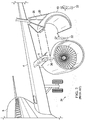
- a turbofan power plant for an aircraft is typically housed within a nacelle 2 that is attached to a wing 4 of an aircraft 6 via an engine strut (or pylon) 8.
- engine strut or pylon 8.
- Some components of engine nacelles are shown in Fig. 1 , and may include an inlet cowl 10, fan cowls 12, thrust reversers 13, exhaust nozzle assembly 16, and of course the turbofan engine assembly 18 itself, among other components.
- Thrust reverser 13 may be secured to, and hoisted by, crane lines 20. While suspended from the crane, personnel 22 present on a work surface 24 may guide the thrust reverser 13 into position by hand, while an additional mechanic 26 may be required to perch on top of engine strut 8 to guide thrust reverser 13 into proper position for installation. This may require mechanic 26 to lean outward over work surface 24 of the factory floor perhaps a dozen or more feet below in order to guide the nacelle component into place by eye, all while perched on the uneven and typically angled surface of engine strut 8. Not only does this create the potential for falling and accompanying injury, but when the nacelle fairings are absent such a fall may result in a landing on engine components.
- US 3433459 discloses a portable jet engine hoist.
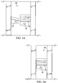
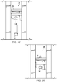
- Thrust reverser 13 typically attaches to engine strut 8 via a hinge assembly 28 as shown in Figs. 3A-3D , and once the thrust reverser is guided into an appropriate position so that the first hinge component 30 (typically the hinge lug) attached to engine strut 8 is aligned with second hinge component 32 (typically the hinge clevis) on the thrust reverser, mechanic 26 may be required to reach downward and insert the requisite hinge pin 34 into the hinge assembly to secure the thrust reverser to the nacelle, followed by installation of an appropriate nut.
- first hinge component 30 typically the hinge lug
- second hinge component 32 typically the hinge clevis
- nacelle components therefore represents a delicate and time-consuming operation requiring large pieces of airplane structure be gently and slowly brought together, and placed into alignment, while suspended from the air.
- the movement of these components may be guided by hand and by eye, and so may require a worker with excellent judgment, extensive experience, and/or specialized training.
- operations may require the use of an overhead crane, equipment which may be in high demand on the factory floor, the operation threatens to create a bottleneck in operations until it is complete.
- the present disclosure provides systems and methods for moving a vehicle component relative to the vehicle.
- the disclosure provides a system for moving a vehicle component of a vehicle relative to a structure of the vehicle during installation of the component on the structure, the system including: Spaced-apart first and second supports mounted to a base on opposite sides of a component bay region of the base, the first and second supports extending upwardly from the base; a lift frame including a crossbeam extending between the first and second supports along a beam axis, and a pair of spaced-apart cambered truss assemblies secured to the crossbeam and configured to be attached to and support the vehicle component relative to the crossbeam; first and second crossbeam support assemblies on the first and second supports, configured to support the crossbeam for rotation of the crossbeam relative to the first and second supports, the first and second crossbeam support assemblies being movable along the first and second supports; a first lift mechanism configured to move the first crossbeam support assembly along the first support in response to a first control signal; a rotational drive mechanism configured to rotate the crossbeam about the beam axis relative to
- the disclosure provides a method of moving a vehicle component of a vehicle relative to a structure of the vehicle during installation of the component on the structure, the method including: Attaching a lift frame to the vehicle component, where the lift frame includes a crossbeam and a pair of spaced-apart cambered truss assemblies attached to the crossbeam, and attaching the lift frame to the vehicle component includes securing the pair of truss assemblies to the vehicle component at a plurality of spaced locations; supporting a first end of the crossbeam with a first crossbeam support assembly; moving by a first lift mechanism in response to a first control signal the vehicle component by moving the first crossbeam support assembly along a first support mounted to and extending upwardly from a base supported on a work surface; rotating by a rotational drive mechanism in response to a second control signal the lift frame and the attached vehicle component about a beam axis relative to the first crossbeam support assembly to change the orientation of the vehicle component relative to the vehicle; and changing the orientation of the vehicle component relative
- the disclosure provides a system for moving a vehicle component of a vehicle relative to a structure of the vehicle during installation of the component on the structure, the system including: spaced-apart first and second supports mounted to a base on opposite sides of a component bay region of the base, the first and second supports extending upwardly from the base; a lift frame including a crossbeam extending along a crossbeam line between the first and second supports, and a pair of spaced-apart cambered truss assemblies secured to the crossbeam and configured to be attached to and support the vehicle component relative to the crossbeam; a first and second crossbeam support assemblies on the first and second supports, configured to support the crossbeam relative to the first and second supports, the first and second crossbeam support assemblies being movable along the first and second supports; a first lift mechanism configured to move the first crossbeam support assembly along the first support in response to a first control signal; a second lift mechanism configured to move the second crossbeam support assembly along the second support in response to a second control
- moving and positioning systems of the present disclosure may be illustrated in the context of aircraft manufacture, and moving and positioning engine components of an aircraft, the disclosed systems may be used in conjunction with the manufacture and/or assembly of any of a variety of vehicles or other structures.
- the present disclosure should not be considered in any way limited to the specific applications and examples illustrated herein.
- System 40 may have utility for the movement of any of a variety of vehicle components, but may exhibit particular utility for moving a vehicle component such as thrust reverser 13, among other components, relative to the structure of the vehicle 6, and may particularly facilitate installation of the component on the structure of the vehicle.
- System 40 may include a base 42, equipped with a plurality of wheels 41, so that base 42 is movable.
- Base 42 may be further equipped with one or more base-drive mechanisms 43 to supply power to wheels 41.
- each wheel 41 may have a dedicated base-drive mechanism 43 to supply power to that wheel.
- base 42 of system 40 may be maneuvered as desired by differentially powering each base-drive mechanism to move base 42 in any direction.
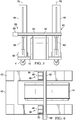
- System 40 includes spaced-apart first 44 and second 46 upright supports mounted to base 42 so as to be on opposite sides of a component bay region 48 of base 42.
- First 44 and second 46 supports are mounted to base 42 so that the first 44 and second 46 upright supports extend upwardly from base 42.
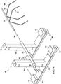
- System 40 further includes a lift frame 50, where the lift frame includes a crossbeam 52 extending between first 44 and second 46 upright supports along a beam axis 54, or crossbeam line, where beam axis 54 is defined by the longitudinal axis of crossbeam 52.
- Lift frame 50 may further include a pair of spaced-apart and cambered truss assemblies 56 that are secured to crossbeam 52, where truss assemblies 56 are configured to be attached to and support vehicle component 14 relative to crossbeam 52.
- System 40 further includes a first 58 and a second 60 crossbeam support assembly movably coupled to the first 44 and second 46 upright supports, so that first 58 and second 60 crossbeam support assemblies are configured to support crossbeam 52, and may be moved along the first 44 and second 46 upright supports.
- First 58 and second 60 crossbeam support assemblies are configured to support crossbeam 52 relative to first 44 and second 46 upright supports.
- First 58 and second 60 crossbeam support assemblies may include a tubular outer support beam 62 extending between first 44 and second 46 upright supports, more particularly, support beam 62 may be configured so that tubular outer support beam 62 encloses crossbeam 52.
- First 58 and second 60 crossbeam support assemblies areat least substantially enclosed within the first 44 and second 46 upright supports, respectively, while supporting outer support beam 62 outside the upright supports, as shown in Fig. 6 .
- first support member 72, first crossbeam support assembly 58, and crossbeam 52 are configured to allow crossbeam 52 to pivot about a first pivot axis 64 that is transverse to beam axis 54.
- pivot axis 64 is fixed relative to upright support 44.
- first crossbeam support assembly 58 and crossbeam 52 may be collectively configured to allow crossbeam 52 to move laterally with respect to first support member 72, as is shown for second crossbeam support assembly 60 in the illustrated example.
- System 40 includes a first lift mechanism 66 that is configured to move the first crossbeam support assembly 58 along the first upright support 44 in response to a first control signal, and a rotational drive mechanism 68 that is configured to rotate crossbeam 52 about beam axis 54 relative to the first 58 and second 60 crossbeam support assemblies in response to a second control signal.
- First 58 and second 60 crossbeam support assemblies are configured to support crossbeam 52 as it is rotated about axis 54, and pivoted about axes 64 and 86 relative to the first 44 and second 46 upright supports.
- First crossbeam support assembly 58 includes a first crossbeam support element 70, shown as a portion of outer support beam 62, supporting crossbeam 52, first support member 72 supported by the first lift mechanism 66 for movement along a first lift line 74 along first upright support 44, and a pivot pin 76 pivotingly coupling first crossbeam support element 70 to first support member 72.
- First lift mechanism 66 may be disposed within upright support 44, beneath and operatively coupled to first support member 72, as shown in Fig. 5 .
- First crossbeam support assembly 58 may further include a sleeve 78 fixedly mounted to one of first crossbeam support element 70 of outer support beam 62 and first support member 72, and pivot pin 76 may be pivotingly supported in sleeve 78 and supported by the other of first crossbeam support element 70 and first support member 72.
- pin 76 is rigidly attached to outer support beam 62 and sleeve 78 is rigidly attached to support member 72, such as by welding, thereby preventing pin 76, outer support beam 62, and crossbeam 52 from moving laterally of lift line 74 along upright support 44.
- System 40 is controlled by an electronic system controller 80 operatively coupled to the plurality of base drive mechanisms 43, and configured to generate control signals to the base drive mechanisms 43 via the conductor(s) 87 to change the position of base 42 of system 40 by selectively rotating base wheels 41 to achieve the desired motion for base 42.
- an electronic system controller 80 operatively coupled to the plurality of base drive mechanisms 43, and configured to generate control signals to the base drive mechanisms 43 via the conductor(s) 87 to change the position of base 42 of system 40 by selectively rotating base wheels 41 to achieve the desired motion for base 42.
- System 40 is controlled by an electronic system controller 80 operatively coupled to first lift mechanism 66, and rotational drive mechanism 68, as shown in the diagram of Fig. 10 .
- Electronic system controller 80 is configured to generate a first control signal controlling operation of first lift mechanism 66 via conductor 81 in order to move first crossbeam support assembly 58 along the first support member 72.
- Electronic system controller 80 is similarly configured to generate a second control signal controlling operation of rotational drive mechanism 68 via conductor 83 in order to rotate crossbeam 52 relative to first crossbeam support assembly 58. In this way electronic system controller 80 is capable of changing the position of vehicle component 14 relative to vehicle 6.
- electronic system controller 80 is configured to receive input information associated with an objective position of vehicle component 14, and in response to the received input information, electronic system controller 80 generates the first control signal for controlling operation of the first lift mechanism 66 to move first crossbeam support assembly 58 along first support member 72, and generates the second control signal for controlling operation of rotational drive mechanism 68 to rotate crossbeam 52 relative to first crossbeam support assembly 58 so as to rotationally position vehicle component 14 when supported by lift frame 50.
- second upright support 46, second crossbeam support assembly 60, and crossbeam 52 are collectively configured to allow crossbeam 52 to pivot as well as move laterally with respect to second upright support 46.
- Second crossbeam support assembly 60 may include a second crossbeam support element 79, shown as a portion of outer support beam 62, supporting crossbeam 52, a second support member 84 supported by the second lift mechanism 82 for movement along a second lift line 75 along second upright support46, and a pivot pin 88 pivotingly coupling second crossbeam support element 79 to second support member 84.
- Second lift mechanism 82 may be disposed within upright support 46, beneath and operatively coupled to second support member 84, as shown in Fig. 5 .
- Second lift mechanism 82 is configured to move second crossbeam support assembly 60 along second support member 84 in response to a third control signal via conductor 85 as shown in Fig. 10 .
- electronic system controller 80 may be operatively coupled to second lift mechanism 82 and configured to generate the third control signal controlling operation of second lift mechanism 82 in order to move second crossbeam support assembly 60 along second support member 84 and thereby change the position of vehicle component 14 relative to vehicle 6.
- Second lift mechanism 82 may be disposed within upright support 46, beneath and operatively coupled to second support member 84, as shown in Fig. 5 .
- electronic system controller 80 is configured to receive input information associated with an objective position of vehicle component 14, and in response to the received input information, electronic system controller 80 generates the first control signal for controlling operation of the first lift mechanism 66 to move first crossbeam support assembly 58 along first support member 72, and generates the second control signal for controlling operation of rotational drive mechanism 68 to rotate crossbeam 52 relative to first crossbeam support assembly 58 so as to rotationally position vehicle component 14 when supported by lift frame 50.
- Second cross beam support assembly 60 may be configured so that, when crossbeam 52 is rotated relative to first crossbeam support assembly 58, crossbeam 52 may additionally be free to rotate around a second pivot axis 86 that is transverse to the beam axis 54 by rotating around second pivot pin 88 while the second crossbeam support assembly 60 is supported by second pivot pin 88.
- system 40 may include an electronic system controller 80 that is operatively coupled to both the first lift mechanism 66 and second lift mechanism 82, where electronic system controller 80 may be configured to generate the first control signal controlling operation of first lift mechanism 66 to move first crossbeam support assembly 58 along first support member 72, and to generate the second control signal controlling operation of second lift mechanism 68 to move second crossbeam support assembly 60 along second support member 84.
- second crossbeam support element 79 During movement of second crossbeam support assembly along second support member 84, second crossbeam support element 79, and thereby outer support beam 62 and crossbeam 52, are allowed to pivot about axis 86 as well as move laterally along second support member 84 via rotation and lateral movement of second pivot pin 88 relative to second support member 84, to thereby change the position of vehicle component 14 relative to vehicle 6. It will be appreciated that since pivot pin 76 is fixed in lateral position relative to first support member 72, pivoting of outer support beam 62 and crossbeam 52 about pin 76, as shown in Fig. 8 , causes the lateral position of pin 88 to change. This change is accommodated by the lateral movement of pin 88 among second support member 84.
- electronic system controller 80 may be configured to receive input information associated with an objective position of vehicle component 14, and in response to the received input information to generate the first control signal for controlling operation of first lift mechanism 66 to move first crossbeam support assembly 58 along first support member 72, and to generate the second control signal for controlling operation of second lift mechanism 82 to move second crossbeam support assembly 60 along the second support member 82.
- vehicle component 14 can be lifted and/or lowered along first 44 and second 46 upright supports, pivoted about axes 64 and 86 relative to the upright supports, moved laterally with respect to second upright support 46, and rotated relative to outer support beam 62, in order to be accurately positioned in a desired position and orientation with respect to vehicle 6.
- system 40 is shown in combination with vehicle component 14, where system 40 is positioned so that vehicle component 14 is disposed within component bay region 48 of base 42 of system 40.
- first lift mechanism 66 In this position, operation of first lift mechanism 66, second lift mechanism 82, rotational drive mechanism 68, first crossbeam support assembly 58, and second crossbeam support assembly 60 so that truss assembly 56 is positioned appropriately for attachment of truss assembly 56 to vehicle component 14.
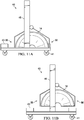
- first lift mechanism 66 and second lift mechanism 82 are operated to raise vehicle component 14 sufficiently to permit free movement of system 40, as shown in Fig. 11B .
- rotational drive mechanism 68 can be employed to rotate vehicle component 14 around beam axis 54 into an appropriate orientation for attachment to vehicle 6.
- movement of base 42 of system 40 coupled with any additional adjustments by one or more of first lift mechanism 66, second lift mechanism 82, rotational drive mechanism 68, first crossbeam support assembly 58, and second crossbeam support assembly 60 can be used to substantially align vehicle component 14 for coupling to vehicle 6.
- system 40 for moving a vehicle component may exhibit particular utility as a component of a positioning system 90 for positioning an engine component 92 for attachment to an engine 94 of an aircraft 96, an example of which is shown in Fig. 12 .
- Positioning system 90 may include a work platform 98 that permits mechanics or other service personnel to be near to the point of attachment of the engine component 92 to aircraft 96, without requiring any worker to balance atop an aircraft structure, or stand beneath a suspended load.
- Positioning system 90 may include some or all of the components for moving engine component 92 similar to those recited above for moving system 40.
- positioning system 90 may include a base 142, equipped with a plurality of wheels 141, so that base 142 is movable.
- Base 142 may be further equipped with one or more base-drive mechanisms 143 to supply power to wheels 141, and in one example of positioning system 90 each wheel 141 may have a dedicated base-drive mechanism 143 to supply power to that wheel, so that base 42 may be moved in any direction as desired on work surface 24.
- Base 142 of positioning system 90 includes spaced-apart first 144 and second 146 upright supports mounted to base 142 so as to be on opposite sides of a component bay region 148 of base 142.
- Positioning system 90 further includes a lift frame 150 including a frame crossbeam 152 and a truss assembly 156 that includes a pair of cambered trusses 158 having respective apexes 160. Trusses 158 may be secured at apexes 160 at spaced-apart positions to frame crossbeam 152. Trusses 158 may further include distal ends 162 that may be configured to be secured at spaced-apart positions to the engine component 92, when secured by positioning system 90.
- Positioning system 90 further includes a crossbeam support 164 on which frame crossbeam 152 may be supported for rotation relative to crossbeam support 164, where crossbeam support 164 is supported by, and configured for relative movement along, the pair of upright supports 144 and 146.
- crossbeam support 164 is configured to span between the pair of upright supports 144 and 146.
- Positioning system 90 includes a lift mechanism 166 configured to move crossbeam support 164 along at least one of upright supports 144 and 146. Positioning system 90 additionally includes a rotational drive 168 configured to rotate frame crossbeam 152 relative to crossbeam support 164, as described for moving system 40.
- positioning system 90 is configured to move engine component 92 so as to place engine component 92 in an appropriate position where it may be attached to an engine 94 of an aircraft 96. Additionally, positioning system 90 includes an alignment assembly 170 for determining how positioning system 90 should move in order to guide engine component 92 into that appropriate position.
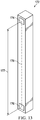
- Alignment assembly 170 includes one or more laser assemblies 172, as shown in Fig. 13 .
- Laser assembly 172 is configured to support a first laser 174 and a second laser 176 so that they are disposed a known distance 177 apart along a reference line 178.
- Laser assembly 172 is configured to be positioned relative to engine component 92 with reference line 178 oriented vertically, and with first 174 and second 176 lasers being individually adjustable in a plane 180 that includes reference line 178 so as to align a laser beam of each of first 174 and second 176 lasers, respectively, with a target position 182 on aircraft 96 associated with aircraft engine 94.
- Laser assembly 172 is configured to provide a first indication representative of a first angle 184 of first laser beam 185 of first laser 174 relative to reference line 178 and a second indication representative of a second angle 186 of the second laser beam 187 of the second laser 176 relative to reference line 178.
- the one or more laser assemblies 172 are attached to work platform 98, as shown in Fig. 12 , which depicts four laser assemblies 172 in association with work platform 98 of positioning system 90.
- the laser assemblies 172 of Fig. 12 are depicted in a retracted configuration B in order to protect the laser assemblies from collisions and incidental damage while securing and/or hoisting vehicle component 92.
- alignment assembly 170 for positioning system 90 further includes a system controller 190 that is configured to control the operation of rotational drive 168 in order to rotate frame crossbeam 152 relative to crossbeam support 164 to rotationally position engine component 92 as it is secured to lift frame 150.
- System controller 190 is additionally be configured to determine a vertical distance 192 between engine component 92 and target position 182 on aircraft 96, as shown in Fig. 14 , based at least in part on the first and second angles and the known distance.
- System controller 190 is further configured to control operation of lift mechanism 166 so as to move crossbeam support 164 along at least one of upright supports 144 and 146 of positioning system 90 in a direction that reduces the vertical distance between engine component 92 and engine 94.
- base drive mechanisms 143 may be coupled to system controller 190, so that system controller 190 could employ base-drive mechanisms 143 to move base 142 along a work surface 24.
- System controller 190 may be further configured to determine a horizontal distance 194 between engine component 92 and target position 182 on aircraft 96 based at least in part on the first and second angles and the known distance.
- System controller 190 may be further configured to control operation of base-drive mechanisms 143 so as to move base 142 along work surface 24 in a direction that reduces the horizontal distance between engine component 92 and engine 94.
- Target position 182 on aircraft 96 may be a location for attachment of engine component 92.
- target position 182 on aircraft 96 may be the position of first hinge component 30.
- laser assembly 172 may be configured to be positioned relative to engine component 92 with first laser 174 positioned proximate to second hinge component 32, with reference line 178 oriented vertically, and with first 174 and second 176 lasers being disposed in a reference plane 180 (coincident with the plane of Fig. 14 ) that includes reference line 178 so as to align a laser beam of each of first 174 and second 176 lasers, respectively, with hinge component 30 on aircraft 96.
- laser assembly 172 of positioning system 90 is configured to support the first 174 and second 176 lasers in a deployed configuration A, as shown in Fig. 14 , such that first laser 174 may be positioned proximate to second hinge component 32 of hinge assembly 28, as such a proximate position aids in the accuracy of system controller 190 in positioning engine component 92.
- laser assembly 172 may also be configured to support the first 174 and second 176 lasers in a retracted configuration B, also shown in Fig. 14 such that the first 174 and second 176 lasers are spaced away from engine component 92, so as to protect the first 174 and second 176 lasers from collisions and consequent damage while positioning system 90 is being moved.
- System controller 190 may therefore be additionally configured to control operation of base-drive mechanisms 143 while the first 174 and second 176 lasers are in their retracted configuration, as shown for example in Fig. 12 .
- System controller 190 employs first 174 and second 176 lasers of laser assembly 172 to calculate a distance and bearing between a location on engine component 92, such as second hinge component 32, and a target position 182 on aircraft 96, such as first hinge component 30.
- Laser assembly 172 may be deployed proximal to engine component 92, with one of the first 174 and second 176 lasers adjacent to second hinge component 32. As shown in the semi-schematic diagram of Fig. 14 showing laser assembly 172, including first 174 and second 176 lasers adjacent an engine component 92. When appropriately deployed, first and second lasers are disposed along reference line 178, and furthermore are disposed a known distance 177 apart, as shown in Figs.13 and 14 . To determine the relative position of engine component 92 with respect to target position 182, the laser beams 185 and 198 emitted by first 174 and second 176 lasers, respectively, are each aligned with target position 182, as shown.
- the reference line 178 (side a), first laser beam 185 (side b), and second laser beam 187 (side c) form a typically scalene or isosceles triangle having three sides, the vertices of which correspond to target position 182 and the first 174 and second 176 lasers.
- First 174 and second 176 lasers are configured so that as their respective laser beams 185 and 187 are aligned with target position 182, the elevation angle of each laser beam above a horizontal plane is determined by angle indicators 200 and 202, respectively. Using the elevation angles, angle 184 between first laser beam 185 and reference line 178, and angle 186 between second laser beam 187 and reference line 178 may be readily calculated. Once angles 184 and 186 are known, third angle 204 between first laser beam 185 and second laser beam 187 at target position 182 may be readily calculated.
- upper laser 174 has been aimed at target position 182, and as a result upper laser beam 185 is elevated 27 degrees above the horizontal plane.
- lower laser 176 is aimed at target position 182, and as a result lower laser beam 187 is elevated 38 degrees above the horizontal plane.
- Upper laser 174 and lower laser 176 are separated vertically by a distance of 36 inches (914 mm).
- angle C is therefore 90 degrees + 27 degrees, or 117 degrees.
- angle B is 90 degrees - 38 degrees, or 52 degrees.
- Angle A must therefore be 11 degrees (180 - (117 + 52)).
- the horizontal distance from upper laser 174 to target position 182 is calculated to be 132.8 inches (337.3 cm)
- the distance from lower laser 176 to target position 182 is calculated to be 132.4 inches (336.3 cm)
- engine component 92 needs to move 132.6 inches (336.8 cm) closer to target position 182.
- a similar calculation provides a vertical distance between upper laser 174, which is adjacent to second hinge component 32, and the target position 182 of 67.6 inches inches (172 cm).
- the vertical distance between lower laser 176 and target position 182 can be calculated to be 103.4 inches (263 cm).
- the second hinge component 32 By subtracting fixed distance 177, or 36 inches (91 cm), the second hinge component 32 must be raised 103.4 inches - 36 inches, or 67.4 inches (172 cm), essentially the same distance.
- System controller 190 can therefore align second hinge component 32 of engine component 92 with the first hinge component 30 at target position 182 by controlling the operation of base-drive mechanism 143 so as to move engine component 92 a distance of 133 inches forward, and controlling lift mechanism 166 so as to raise engine component 92 a distance of 67 inches.
- the combined result of both the forward motion and the upward lift will dispose second hinge component 32 on engine component 92 in alignment with or adjacent to first hinge component 30 on aircraft 96.
- System 40 of the present disclosure may be particularly well-suited to carrying out a method of moving a vehicle component of a vehicle relative to a structure of the vehicle during installation of the component on the structure, as set out in flowchart 208 of Fig. 15 .
- the method may include: attaching a lift frame to the vehicle component, where the lift frame includes a crossbeam and a pair of spaced-apart cambered truss assemblies attached to the crossbeam, and attaching the lift frame to the vehicle component includes securing the pair of truss assemblies to the vehicle component at a plurality of spaced locations, at step 210 of flowchart 208; supporting a first end of the crossbeam with a first crossbeam support assembly, at step 212 of flowchart 208; moving by a first lift mechanism in response to a first control signal the vehicle component by moving the first crossbeam support assembly along a first support mounted to and extending upwardly from a base supported on a work surface, at step 214 of flowchart 208; rotating
- the method of flowchart 208 may further include the steps of receiving by the electronic controller input information related to alignment of a first laser and second laser positioned proximate the vehicle component with respect to a target installation point on the vehicle structure, which input information is representative of an objective position and orientation of the vehicle component relative to the vehicle structure; generating by the electronic controller in response to the received input information the first control signal for controlling operation of the first lift mechanism to move the first crossbeam support assembly along the first support; and generating by the electronic controller in response to the received input information the second control signal for controlling operation of the rotational drive mechanism to rotate the crossbeam and the attached vehicle component relative to the first crossbeam support assembly.
- the method of flowchart 208 may further include the steps of receiving by the electronic controller input information associated with an objective position of the vehicle component; in response to the received input information, generating the first control signal for controlling operation of the first lift mechanism to move the first crossbeam support assembly along the first support; and generating the second control signal for controlling operation of the rotational drive mechanism to rotate the crossbeam relative to the first crossbeam support assembly to rotationally position the vehicle component when supported by the lift frame.
- moving the first crossbeam support assembly along a first support mounted to and extending upwardly from a base supported on a work surface additionally includes pivoting the crossbeam relative to the first support about a first pivot axis that is transverse to the beam axis.
- Pivoting the crossbeam relative to the first support may include supporting the crossbeam by a first crossbeam support element, supporting a first support member by the first lift mechanism for movement along a first lift line along the first support, and pivoting the first crossbeam support element about a pivot pin pivotingly coupling the first crossbeam support element to the first support member.
- the method may further include moving the second crossbeam support element relative to the second support member along a lateral line transverse to the second lift line.
- the method of flowchart 208 may further include the step of moving the crossbeam laterally of the second support.
- the method of flowchart 208 may additionally include the steps of supporting a second end of the crossbeam with a second crossbeam support assembly movable along a second support mounted to and extending upwardly from the base; moving the second crossbeam support assembly along the second support by a second lift mechanism in response to a third control signal; and generating by the electronic controller the third control signal controlling operation of the second lift mechanism to move the second crossbeam support assembly along the second support, to thereby change the position of the vehicle component relative to the vehicle.
- Positioning system 90 may be particularly well-suited to carrying out a method of positioning an engine component for attachment to an engine of an aircraft, as set out in flowchart 220 of Fig. 16 .
- Such a method may include attaching the engine component to a lift frame including a frame crossbeam and a pair of cambered trusses having respective apexes, the trusses being secured at their apexes at spaced-apart positions to the frame crossbeam, and having distal ends secured at spaced-apart positions to the engine component, at step 222 of flowchart 220; moving by a lift mechanism the engine component by moving a crossbeam support within which the frame crossbeam is supported, the crossbeam support configured for relative movement along two upright supports extending upwardly from a base at step 224 of flowchart 220; rotating by a rotational drive the lift frame and the attached engine component relative to the crossbeam support to orient the engine component relative to the engine at step 226 of flowchart 220; supporting first and second
- the method of flowchart 220 may further include determining by the system controller a horizontal distance between the engine component and the target position on the aircraft based at least in part on the first and second angles and the known distance; and controlling operation of a base-drive mechanism coupled to the system controller and configured to move the base along a work surface, in a manner moving the base along the work surface in a direction that reduces the horizontal distance between the engine component and the engine.
- the method of flowchart 220 may further include moving the first and second lasers away from the engine component after determining the first angle of the first laser beam and the second angle of the second laser beam and before controlling operation of the base-drive mechanism to move the crossbeam support along the work surface.
- supporting the first and second lasers proximate to the engine component may additionally include positioning the first laser proximate to a first hinge component of a hinge used to mount the engine component to the aircraft with the hinge including the first hinge component on the engine component and a second hinge component on the aircraft, and the target position on the aircraft is a position of the second hinge component.
- the method may additionally include aligning the first hinge component to the second hinge component and securing the first hinge component to the second hinge component, and subsequently moving the first and second lasers away from the engine component after determining the first angle of the first laser beam and the second angle of the second laser beam and before controlling operation of the lift mechanism to move the crossbeam support along the at least one upright support in a direction that reduces the vertical distance between the engine component and the engine.
- the system controller may be configured to control operation of the base-drive mechanism after the first and second lasers have been moved away from the engine component.
- Example 1 Illustrative Data Processing System
- data processing system 240 is an illustrative data processing system suitable for implementing aspects of the moving systems and positioning systems of the present disclosure. More specifically and as discussed above, in some examples the moving systems and positioning systems may include a system controller (80, 190) that may be or that may include one or more data processing systems. In performing the functions described above, such as controlling the movement and positioning of a vehicle component and/or calculating the relative positioning of an engine component with respect to a target point, system controller 80, 190 may exhibit some or all of the characteristics of data processing system 240 as shown and as described below.
- system controller 80, 190 may exhibit some or all of the characteristics of data processing system 240 as shown and as described below.
- data processing system 240 includes communications framework 242.
- Communications framework 242 provides communications between processor unit 244, memory 246, persistent storage 248, communications unit 250, input/output (I/O) unit 252, and display 254.
- Memory 246, persistent storage 248, communications unit 250, input/output (I/O) unit 252, and display 254 are examples of resources accessible by processor unit 244 via communications framework 242.
- Processor unit 244 serves to run instructions that may be loaded into memory 246.
- Processor unit 244 may be a number of processors, a multi-processor core, or some other type of processor, depending on the particular implementation. Further, processor unit 244 may be implemented using a number of heterogeneous processor systems in which a main processor is present with secondary processors on a single chip. As another illustrative example, processor unit 244 may be a symmetric multi-processor system containing multiple processors of the same type.
- Memory 246 and persistent storage 248 are examples of storage devices 256.
- a storage device is any piece of hardware that is capable of storing information, such as, for example, without limitation, data, program code in functional form, and other suitable information either on a temporary basis or a permanent basis.
- Storage devices 256 also may be referred to as computer-readable storage devices in these examples.
- Memory 246, in these examples, may be, for example, a random access memory or any other suitable volatile or non-volatile storage device.
- Persistent storage 248 may take various forms, depending on the particular implementation.
- persistent storage 248 may contain one or more components or devices.
- persistent storage 248 may be a hard drive, a flash memory, a rewritable optical disk, a rewritable magnetic tape, or some combination of the above.
- the media used by persistent storage 248 also may be removable.
- a removable hard drive may be used for persistent storage 248.
- Communications unit 250 in these examples, provides for communications with other data processing systems or devices.
- communications unit 250 is a network interface card.
- Communications unit 250 may provide communications through the use of either or both physical and wireless communications links.
- Input/output (I/O) unit 252 allows for input and output of data with other devices that may be connected to data processing system 240.
- input/output (I/O) unit 252 may provide a connection for user input through a keyboard, a mouse, and/or some other suitable input device.
- input/output (I/O) unit 252 may send output to a printer.
- Display 254 provides a mechanism to display information to a user.
- Instructions for the operating system, applications, and/or programs may be located in storage devices 256, which are in communication with processor unit 244 through communications framework 242.
- the instructions are in a functional form on persistent storage 248. These instructions may be loaded into memory 246 for execution by processor unit 244.
- the processes of the different examples may be performed by processor unit 244 using computer-implemented instructions, which may be located in a memory, such as memory 246.
- program instructions are referred to as program instructions, program code, computer usable program code, or computer-readable program code that may be read and executed by a processor in processor unit 244.
- the program code in the different examples may be embodied on different physical or computer-readable storage media, such as memory 246 or persistent storage 248.
- Program code 258 is located in a functional form on computer-readable media 260 that is selectively removable and may be loaded onto or transferred to data processing system 240 for execution by processor unit 244.
- Program code 258 and computer-readable media 260 form computer program product 262 in these examples.
- computer-readable media 260 may be computer-readable storage media 264 or computer-readable signal media 266.
- Computer-readable storage media 264 may include, for example, an optical or magnetic disk that is inserted or placed into a drive or other device that is part of persistent storage 248 for transfer onto a storage device, such as a hard drive, that is part of persistent storage 248.
- Computer-readable storage media 264 also may take the form of a persistent storage, such as a hard drive, a thumb drive, or a flash memory, that is connected to data processing system 240. In some instances, computer-readable storage media 264 may not be removable from data processing system 240.
- computer-readable storage media 264 is a physical or tangible storage device used to store program code 258 rather than a medium that propagates or transmits program code 258.
- Computer-readable storage media 264 is also referred to as a computer-readable tangible storage device or a computer-readable physical storage device. In other words, computer-readable storage media 264 is a media that can be touched by a person.
- program code 258 may be transferred to data processing system 240 using computer-readable signal media 266.
- Computer-readable signal media 266 may be, for example, a propagated data signal containing program code 258.
- Computer-readable signal media 266 may be an electromagnetic signal, an optical signal, and/or any other suitable type of signal. These signals may be transmitted over communications links, such as wireless communications links, optical fiber cable, coaxial cable, a wire, and/or any other suitable type of communications link.
- the communications link and/or the connection may be physical or wireless in the illustrative examples.
- program code 258 may be downloaded over a network to persistent storage 248 from another device or data processing system through computer-readable signal media 266 for use within data processing system 240.
- program code stored in a computer-readable storage medium in a server data processing system may be downloaded over a network from the server to data processing system 240.
- the data processing system providing program code 258 may be a server computer, a client computer, or some other device capable of storing and transmitting program code 258.
- data processing system 240 may include organic components integrated with inorganic components and/or may be comprised entirely of organic components excluding a human being.
- a storage device may be comprised of an organic semiconductor.
- processor unit 244 may take the form of a hardware unit that has circuits that are manufactured or configured for a particular use. This type of hardware may perform operations without needing program code to be loaded into a memory from a storage device to be configured to perform the operations.
- processor unit 244 when processor unit 244 takes the form of a hardware unit, processor unit 244 may be a circuit system, an application specific integrated circuit (ASIC), a programmable logic device, or some other suitable type of hardware configured to perform a number of operations.
- ASIC application specific integrated circuit
- a programmable logic device the device is configured to perform the number of operations. The device may be reconfigured at a later time or may be permanently configured to perform the number of operations.
- Examples of programmable logic devices include, for example, a programmable logic array, a field programmable logic array, a field programmable gate array, and other suitable hardware devices.
- program code 258 may be omitted, because the processes for the different examples are implemented in a hardware unit.
- processor unit 244 may be implemented using a combination of processors found in computers and hardware units.
- Processor unit 244 may have a number of hardware units and a number of processors that are configured to run program code 258. With this depicted example, some of the processes may be implemented in the number of hardware units, while other processes may be implemented in the number of processors.
- a bus system may be used to implement communications framework 242 and may be comprised of one or more buses, such as a system bus or an input/output bus.
- the bus system may be implemented using any suitable type of architecture that provides for a transfer of data between different components or devices attached to the bus system.
- communications unit 250 may include a number of devices that transmit data, receive data, or both transmit and receive data.
- Communications unit 250 may be, for example, a modem or a network adapter, two network adapters, or some combination thereof.
- a memory may be, for example, memory 246, or a cache, such as that found in an interface and memory controller hub that may be present in communications framework 242.
- each block in the flowcharts or block diagrams may represent a module, segment, or portion of code, which comprises one or more executable instructions for implementing the specified logical function or functions.
- the functions noted in a block may occur out of the order noted in the drawings. For example, the functions of two blocks shown in succession may be executed substantially concurrently, or the functions of the blocks may sometimes be executed in the reverse order, depending upon the functionality involved.
- Example 2 Illustrative Distributed Data Processing System
- Network data processing system 270 may be interchangeably termed a network, a computer network, a network system, a distributed data processing system, or a distributed network, aspects of which may be included in one or more illustrative examples of the moving systems and positioning systems of the present disclosure.
- system controller 80, 190 of the disclosed systems may communicate over a network in order to coordinate with other equipment being used in a manufacturing facility, or to access processing centers remote from the system controller itself, among other applications.
- FIG. 18 is provided as an illustration of one implementation and is not intended to imply any limitation with regard to environments in which different examples may be implemented. Many modifications to the depicted environment may be made.
- Network data processing system 270 is a network of computers, each of which is an example of data processing system 240, and other components.
- Network data processing system 270 may include network 272, which is a medium configured to provide communications links between various devices and computers connected together within network data processing system 270.
- Network 272 may include connections such as wired or wireless communication links, fiber optic cables, and/or any other suitable medium for transmitting and/or communicating data between network devices, or any combination thereof.
- a first network device 274 and a second network device 276 connect to network 272, as does an electronic storage device 278.
- Network devices 274 and 276 are each examples of data processing system 240, described above.
- devices 274 and 276 are shown as server computers.
- network devices may include, without limitation, one or more personal computers, mobile computing devices such as personal digital assistants (PDAs), tablets, and smart phones, handheld gaming devices, wearable devices, tablet computers, routers, switches, voice gates, servers, electronic storage devices, imaging devices, and/or other networked-enabled tools that may perform a mechanical or other function.
- PDAs personal digital assistants
- These network devices may be interconnected through wired, wireless, optical, and other appropriate communication links.
- client electronic devices such as a client computer 280, a client laptop or tablet 282 and/or a client smart device 284, may connect to network 272.
- client electronic devices 280, 282, and 284 may include, for example, one or more personal computers, network computers, and/or mobile computing devices such as personal digital assistants (PDAs), smart phones, handheld gaming devices, wearable devices, and/or tablet computers, and the like.
- server 274 provides information, such as boot files, operating system images, and applications to one or more of client electronic devices 280, 282, and 284.
- Client electronic devices 280, 282, and 284 may be referred to as "clients" with respect to a server such as server computer 274.
- Network data processing system 270 may include more or fewer servers and clients or no servers or clients, as well as other devices not shown.
- Client smart device 284 may include any suitable portable electronic device capable of wireless communications and execution of software, such as a smartphone or a tablet.
- the term “smartphone” may describe any suitable portable electronic device having more advanced computing ability and network connectivity than a typical mobile phone.
- smartphones may be capable of sending and receiving emails, texts, and multimedia messages, accessing the Internet, and/or functioning as a web browser.
- Smart devices e.g., smartphones
- Smart devices may be capable of connecting with other smart devices, computers, or electronic devices wirelessly, such as through near field communications (NFC), BLUETOOTH ® , WiFi, or mobile broadband networks.
- Wireless connectively may be established among smart devices, smartphones, computers, and other devices to form a mobile network where information can be exchanged.
- Program code located in system 270 may be stored in or on a computer recordable storage medium, such as persistent storage 248 described above, and may be downloaded to a data processing system or other device for use.
- program code may be stored on a computer recordable storage medium on server computer 274 and downloaded for use to client 280 over network 272 for use on client 280.
- Network data processing system 270 may be implemented as one or more of a number of different types of networks.
- system 270 may include an intranet, a local area network (LAN), a wide area network (WAN), or a personal area network (PAN).
- network data processing system 270 includes the Internet, with network 272 representing a worldwide collection of networks and gateways that use the transmission control protocol/Internet protocol (TCP/IP) suite of protocols to communicate with one another.
- TCP/IP transmission control protocol/Internet protocol
- At the heart of the Internet is a backbone of high-speed data communication lines between major nodes or host computers. Thousands of commercial, governmental, educational and other computer systems may be utilized to route data and messages.
- network 270 may be referred to as a "cloud.”
- each server 274 may be referred to as a cloud computing node, and client electronic devices may be referred to as cloud consumers, or the like.
- Fig. 18 is intended as an example, and not as an architectural limitation for any illustrative examples.
- the illustrative examples of the moving systems described herein allow large pieces of aircraft structure to be lifted, transported, and brought into position adjacent the aircraft without required an overhead crane or hoist, and without requiring service personnel to direct the typically heavy structure by hand while it is installed.
- the disclosed moving systems eliminate the need for supplemental movement aids such as cranes, hoists, and even muscle power.
- the configuration of the base of the illustrative moving system permits the moving system to straddle a vehicle component while it remains on a pallet or other shipping platform, and secure it for lifting. Once secured, the vehicle component can be lifted, translated, and rotated independently while secured, allowing the vehicle component to be oriented as necessary to match the aircraft's orientation.
- a work platform to the moving system provides mechanics and service personnel to be close to the points of engagement between engine components and the aircraft, without requiring personnel to balance upon the aircraft itself, or to be stationed below a suspended load.
- the illustrative positioning system disclosed herein employs optical guidance for automated or semi-automated positioning of an engine component - including fine adjustments - without requiring any personnel to be in or near the gap between the engine component and the aircraft. Furthermore, the necessary position adjustments needed to install engine components can be made without relying on unaided eyesight, or professional expertise to achieve component alignment.
- ordinal indicators such as first, second or third, for identified elements are used to distinguish between the elements, and do not indicate a required or limited number of such elements, and do not indicate a particular position or order of such elements unless otherwise specifically stated. Ordinal indicators may be applied to associated elements in the order in which they are introduced in a given context, and the ordinal indicators for such elements may be different in different contexts.
Landscapes
- Engineering & Computer Science (AREA)
- Transportation (AREA)
- Structural Engineering (AREA)
- Life Sciences & Earth Sciences (AREA)
- Geology (AREA)
- Mechanical Engineering (AREA)
- Manufacturing & Machinery (AREA)
- Civil Engineering (AREA)
- Aviation & Aerospace Engineering (AREA)
- Chemical & Material Sciences (AREA)
- Combustion & Propulsion (AREA)
- Automatic Assembly (AREA)
Claims (15)
- System (40, 90) zum Bewegen einer Fahrzeugkomponente (14, 92) eines Fahrzeugs (6, 96) in Bezug zu einer Struktur des Fahrzeugs während des Anbringens der Komponente an der Struktur, wobei das System aufweist:beabstandete erste (44, 144) und zweite (46, 146) Stützen, die an einer Basis (42, 142) an gegenüberliegenden Seiten eines Komponentenzwischenraumbereichs (48, 148) der Basis angebracht sind, wobei sich die ersten und zweiten Stützen von der Basis nach oben erstrecken;einen Hubrahmen (50, 150), der einen Querbalken (52, 152) aufweist, der sich zwischen den ersten und zweiten Stützen entlang einer Balkenachse (54) erstreckt, und ein Paar beabstandeter gewölbter Auslegeranordnungen (56, 156), die an dem Querbalken befestigt und dazu konfiguriert sind, an der Fahrzeugkomponente befestigt zu werden und sie in Bezug zu dem Querbalken zu stützen;erste (58) und zweite (60) Querbalken-Stützanordnungen auf den ersten und zweiten Stützen, die dazu konfiguriert sind, den Querbalken zur Drehung des Querbalkens in Bezug zu den ersten und zweiten Stützen zu stützen, wobei die ersten und zweiten Querbalken-Stützanordnungen entlang der ersten und zweiten Stützen bewegbar sind;einen ersten Hubmechanismus (66), der dazu konfiguriert ist, die erste Querbalken-Stützanordnung (58) im Ansprechen auf ein erstes Steuersignal entlang der ersten Stütze (44, 144) zu bewegen;einen Drehantriebsmechanismus (68, 168), der dazu konfiguriert ist, den Querbalken (52, 152) im Ansprechen auf ein zweites Steuersignal um die Balkenachse (54) in Bezug zu den ersten (58) und zweiten (60) Querbalken-Stützanordnungen zu drehen; undeinen elektronischen Controller (80, 190), der betriebsbereit mit dem ersten Hubmechanismus (66) und dem Drehantriebsmechanismus (68, 168) verbunden und dazu konfiguriert ist, das erste Steuersignal zu erzeugen, das den Betrieb des ersten Hubmechanismus (66) steuert, um die erste Querbalken-Stützanordnung (58) entlang der ersten Stütze (44, 144) zu bewegen, und das zweite Steuersignal zu erzeugen, das den Betrieb des Drehantriebsmechanismus (68, 168) steuert, um den Querbalken (52, 152) in Bezug zu der ersten Querbalken-Stützanordnung (58) zu drehen, um dadurch eine Position der Fahrzeugkomponente (14, 92) in Bezug zu dem Fahrzeug (6, 96) zu verändern.
- System (40, 90) nach Anspruch 1, wobei der elektronische Controller (90, 180) dazu konfiguriert ist, Eingangsinformationen zu empfangen, die zu einer objektiven Position der Fahrzeugkomponente (14, 92) zugehörig sind, und im Ansprechen auf die empfangenen Eingangsinformationen das erste Steuersignal zum Steuern des Betriebs des ersten Hubmechanismus (66) zu erzeugen, um die erste Querbalken-Stützanordnung (58) entlang der ersten Stütze (44, 144) zu bewegen, und das zweite Steuersignal zum Steuern des Betriebs des Drehantriebsmechanismus (68, 168) zu erzeugen, um den Querbalken (52, 152) in Bezug zu der ersten Querbalken-Stützanordnung (58) zu drehen, um die Fahrzeugkomponente (14, 92) drehend zu positionieren, wenn sie von dem Hubrahmen (50, 150) gestützt wird.
- System (40, 90) nach einem der Ansprüche 1 bis 2, wobei die ersten (58) und zweiten (60) Querbalken-Stützanordnungen einen rohrförmigen äußeren Stützbalken (62) aufweisen, der sich zwischen den ersten (44, 144) und zweiten (46, 146) Stützen erstreckt, wobei der Stützbalken den Querbalken (52, 152) umschließt.
- System (40, 90) nach einem der Ansprüche 1 bis 3, wobei die erste Stütze (44, 144), die erste Querbalken-Stützanordnung (58) und der Querbalken (52, 152) zusammen dazu konfiguriert sind, es dem Querbalken zu ermöglichen, um eine erste Schwenkachse (64) zu schwenken, die querverlaufend zu der Balkenachse (54) ist.
- System (40, 90) nach Anspruch 4, wobei die erste Querbalken-Stützanordnung (58) ein erstes Querbalken-Stützelement (70) aufweist, das den Querbalken (52, 152) stützt, ein erstes Stützteil (72), das von dem ersten Hubmechanismus (66) zur Bewegung entlang einer ersten Hublinie (74) entlang der ersten Stütze (44, 144) gestützt wird, und einen Drehzapfen (76), der das erste Querbalken-Stützelement schwenkend mit dem ersten Stützteil verbindet.
- System (40, 90) nach Anspruch 5, wobei die erste Querbalken-Stützanordnung (58) des Weiteren eine Hülse (78) aufweist, die fest an einem des ersten Querbalken-Stützelements (79) und des ersten Stützteils (72) angebracht ist, und der Drehzapfen (76) schwenkend in der Hülse gestützt wird und von dem anderen des ersten Querbalken-Stützelements und des ersten Stützteils gestützt wird.
- System (40, 90) nach einem der Ansprüche 1 bis 6, wobei die erste Stütze (46, 146), die erste Querbalken-Stützanordnung (60) und der Querbalken (52, 152) zusammen dazu konfiguriert sind, es dem Querbalken zu ermöglichen, sich seitlich von der ersten Stütze (46, 146) zu bewegen.
- System (40, 90) nach einem der Ansprüche 1 bis 7, das des Weiteren einen zweiten Hubmechanismus (82) aufweist, der dazu konfiguriert ist, die zweite Querbalken-Stützanordnung (60) im Ansprechen auf ein drittes Steuersignal entlang der zweiten Stütze (46, 146) zu bewegen; und wobei der elektronische Controller (90) betriebsbereit mit dem zweiten Hubmechanismus verbunden und dazu konfiguriert ist, das dritte Steuersignal zu erzeugen, das den Betrieb des zweiten Hubmechanismus steuert, um die zweite Querbalken-Stützanordnung entlang der zweiten Stütze zu bewegen, um dadurch die Position der Fahrzeugkomponente (14, 92) in Bezug zu dem Fahrzeug (6) zu verändern.
- Verfahren (208) zum Bewegen einer Fahrzeugkomponente (14, 92) eines Fahrzeugs in Bezug zu einer Struktur des Fahrzeugs während des Anbringens der Komponente an der Struktur, wobei das Verfahren die folgenden Schritte aufweist:Befestigen (210) eines Hubrahmens (50, 150) an der Fahrzeugkomponente, wobei der Hubrahmen einen Querbalken (52, 152) und ein Paar beabstandeter gewölbter Auslegeranordnungen (56, 156) aufweist, die an dem Querbalken befestigt sind, und wobei das Befestigen des Hubrahmens an der Fahrzeugkomponente das Befestigen des Paars von Auslegeranordnungen an der Fahrzeugkomponente an einer Vielzahl beabstandeter Stellen aufweist;Stützen (212) eines ersten Endes des Querbalkens mit einer ersten Querbalken-Stützanordnung (58);Bewegen (214), durch den ersten Hubmechanismus (66) im Ansprechen auf ein erstes Steuersignal, der Fahrzeugkomponente durch Bewegen der ersten Querbalken-Stützanordnung (58) entlang einer ersten Stütze (44, 144), die an einer Basis (42, 142), die auf einer Arbeitsfläche (24) gestützt wird, angebracht ist und sich davon nach oben erstreckt;Drehen (216), durch einen Drehantriebsmechanismus (68, 168) im Ansprechen auf ein zweites Steuersignal, des Hubrahmens (50, 150) und der befestigten Fahrzeugkomponente um eine Balkenachse (54) in Bezug zu der ersten Querbalken-Stützanordnung (58), um die Ausrichtung der Fahrzeugkomponente in Bezug zu dem Fahrzeug zu verändern; undVerändern (218) der Ausrichtung der Fahrzeugkomponente in Bezug zu dem Fahrzeug durch Erzeugen, durch einen elektronischen Controller, des ersten Steuersignals, das den Betrieb des ersten Hubmechanismus (66) steuert, um die erste Querbalken-Stützanordnung (58) entlang der ersten Stütze (44, 144) zu bewegen, und des zweiten Steuersignals zum Steuern des Betriebs des Drehantriebsmechanismus (68, 168), um den Hubrahmen und die befestigte Fahrzeugkomponente in Bezug zu der ersten Querbalken-Stützanordnung (58) zu drehen.
- Verfahren (208) nach Anspruch 9, das des Weiteren die folgenden Schritte aufweist:Empfangen, durch den elektronischen Controller (80, 190), von Eingangsinformationen, die sich auf die Ausrichtung eines ersten Lasers (174) und eines zweiten Lasers (176), die in der Nähe der Fahrzeugkomponente (14, 92) positioniert sind, in Bezug zu einem Anbringungs-Zielpunkt (182) auf der Fahrzeugstruktur beziehen, wobei die Informationen für eine objektive Position und Ausrichtung der Fahrzeugkomponente in Bezug zu der Fahrzeugstruktur repräsentativ sind;Erzeugen, durch den elektronischen Controller im Ansprechen auf die empfangenen Eingangsinformationen, des ersten Steuersignals zum Steuern des Betriebs des ersten Hubmechanismus (66), um die erste Querbalken-Stützanordnung (58) entlang der ersten Stütze (44, 144) zu bewegen; undErzeugen, durch den elektronischen Controller im Ansprechen auf die empfangenen Eingangsinformationen, des zweiten Steuersignals zum Steuern des Betriebs des Drehantriebsmechanismus (68, 168), um den Querbalken (52, 152) und die befestigte Fahrzeugkomponente (14, 92) in Bezug zu der ersten Querbalken-Stützanordnung zu drehen.
- Verfahren (208) nach einem der Ansprüche 9 bis 10, das des Weiteren die folgenden Schritte aufweist:Empfangen, durch den elektronischen Controller (80, 190), von Eingangsinformationen, die zu einer objektiven Position der Fahrzeugkomponente (14, 92) zugehörig sind;im Ansprechen auf die empfangenen Eingangsinformationen, Erzeugen des ersten Steuersignals zum Steuern des Betriebs des ersten Hubmechanismus (66), um die erste Querbalken-Stützanordnung (58) entlang der ersten Stütze (44, 144) zu bewegen; undErzeugen des zweiten Steuersignals zum Steuern des Betriebs des Drehantriebsmechanismus (68, 168), um den Querbalken (52, 152) in Bezug zu der ersten Querbalken-Stützanordnung (58, 164) zu bewegen, um die Fahrzeugkomponente drehend zu positionieren, wenn sie von dem Hubrahmen gestützt wird.
- Verfahren (208) nach einem der Ansprüche 9 bis 11, wobei das Bewegen der ersten Querbalken-Stützanordnung (58) entlang der ersten Stütze (44, 144) das Schwenken des Querbalkens (52) in Bezug zu der ersten Stütze um eine erste Schwenkachse (64) aufweist, die querverlaufend zu der Balkenachse (54) ist.
- Verfahren (208) nach Anspruch 12, wobei das Schwenken des Querbalkens (52, 152) in Bezug zu der ersten Stütze (44, 144) das Stützen des Querbalkens durch ein erstes Querbalken-Stützelement (70) aufweist, das Stützen eines ersten Stützteils (72) durch den ersten Hubmechanismus zur Bewegung entlang einer ersten Hublinie (74) entlang der ersten Stütze, und das Schwenken des ersten Querbalken-Stützelements (70) um einen Drehzapfen, der das erste Querbalken-Stützelement schwenkend mit dem ersten Stützteil verbindet.
- Verfahren (208) nach Anspruch 13, das des Weiteren den Schritt des Bewegens des ersten Querbalken-Stützelements (70) in Bezug zu dem ersten Stützteil (44, 144) entlang einer seitlichen Linie quer zu der ersten Hublinie (74) aufweist.
- Verfahren (208) nach einem der Ansprüche 9 bis 14, das des Weiteren die Schritte des Stützens eines zweiten Endes des Querbalkens (52, 152) mit einer zweiten Querbalken-Stützanordnung (60) aufweist, die entlang einer zweiten Stütze (46, 146) bewegbar ist, welche an der Basis (142) angebracht ist und sich davon nach oben erstreckt, des Bewegens der zweiten Querbalken-Stützanordnung entlang der zweiten Stütze durch einen zweiten Hubmechanismus (82) im Ansprechen auf ein drittes Steuersignal, und des Erzeugens, durch den elektronischen Controller (80, 190), des dritten Steuersignals, das den Betrieb des zweiten Hubmechanismus steuert, um die zweite Querbalken-Stützanordnung entlang der zweiten Stütze zu bewegen, um dadurch die Position der Fahrzeugkomponente (14, 92) in Bezug zu dem Fahrzeug (6, 96) zu verändern.
Applications Claiming Priority (1)
| Application Number | Priority Date | Filing Date | Title |
|---|---|---|---|
| US16/382,144 US11634239B2 (en) | 2019-04-11 | 2019-04-11 | Systems and methods for moving a vehicle component relative to the vehicle structure |
Publications (2)
| Publication Number | Publication Date |
|---|---|
| EP3744643A1 EP3744643A1 (de) | 2020-12-02 |
| EP3744643B1 true EP3744643B1 (de) | 2022-01-05 |
Family
ID=69844567
Family Applications (1)
| Application Number | Title | Priority Date | Filing Date |
|---|---|---|---|
| EP20163118.1A Active EP3744643B1 (de) | 2019-04-11 | 2020-03-13 | Systeme und verfahren zum bewegen einer (luft-)fahrzeugkomponente relativ zur (luft-)fahrzeugstruktur |
Country Status (4)
| Country | Link |
|---|---|
| US (1) | US11634239B2 (de) |
| EP (1) | EP3744643B1 (de) |
| JP (1) | JP7534860B2 (de) |
| CN (1) | CN111807271B (de) |
Families Citing this family (6)
| Publication number | Priority date | Publication date | Assignee | Title |
|---|---|---|---|---|
| TR202005987A1 (tr) * | 2020-04-15 | 2021-10-21 | Tuerk Hava Yollari Teknik Anonim Sirketi | Hareketli̇ fan biçaği tutucularina sahi̇p bi̇r taşiyici |
| US11849552B2 (en) * | 2021-05-06 | 2023-12-19 | Manufacturing Design Solutions | Adjustable free-standing support for a data display monitor |
| CN113800376A (zh) * | 2021-09-30 | 2021-12-17 | 海航航空技术有限公司 | 一种飞机发动机更换方法和手扳葫芦 |
| US12403495B2 (en) * | 2022-09-30 | 2025-09-02 | The Boeing Company | Inkjet printing vehicle livery |
| US12403706B2 (en) | 2022-09-30 | 2025-09-02 | The Boeing Company | Robotics for inkjet printing vehicle livery |
| US12479601B2 (en) * | 2024-05-17 | 2025-11-25 | United States Of America As Represented By The Secretary Of The Air Force | Stand for holding a workpiece with three-axis adjustability |
Family Cites Families (23)
| Publication number | Priority date | Publication date | Assignee | Title |
|---|---|---|---|---|
| US3433459A (en) | 1967-05-02 | 1969-03-18 | Federal Sign And Signal Corp | Load handling apparatus |
| JPH0524720Y2 (de) * | 1985-07-30 | 1993-06-23 | ||
| US5188247A (en) | 1991-11-04 | 1993-02-23 | Keith Jastrow | Lifting apparatus |
| JP4023646B2 (ja) | 1998-12-24 | 2007-12-19 | 株式会社ニッケンビルコン | 建築物外装改装方法および建築物外装改装用の下地取出構造 |
| GB0022444D0 (en) | 2000-09-13 | 2000-11-01 | Bae Systems Plc | Positioning system and method |
| US6546616B2 (en) | 2000-12-15 | 2003-04-15 | Bell Helicopter Textron Inc. | Six-axis alignment and installation tool |
| AUPS074602A0 (en) * | 2002-02-25 | 2002-03-21 | Protean Global Pty Ltd | Lifting mechanism for use with health care equipment |
| JP2004142874A (ja) | 2002-10-24 | 2004-05-20 | Oji Logistics Co Ltd | 荷役車輌のクランプ装置 |
| ATE420742T1 (de) * | 2003-11-25 | 2009-01-15 | Guedel Group Ag | Fördereinrichtung zum transport von werkstücken in einer presse |
| US20070210289A1 (en) * | 2006-01-31 | 2007-09-13 | Frank Drake | Powered drive for jack |
| US7587258B2 (en) | 2006-05-10 | 2009-09-08 | The Boeing Company | Merged laser and photogrammetry measurement using precise camera placement |
| US7756321B2 (en) | 2007-02-28 | 2010-07-13 | The Boeing Company | Method for fitting part assemblies |
| WO2010002968A1 (en) | 2008-07-03 | 2010-01-07 | Rotary Lift, A Division Of Dover Industrial Products, Inc. | Vehicle guidance system for automotive lifts |
| US20100213429A1 (en) * | 2009-02-20 | 2010-08-26 | Frank Drake | Jack assembly with multiple degrees of freedom |
| US8634950B2 (en) | 2009-12-14 | 2014-01-21 | Embraer S.A. | Automated positioning and alignment method and system for aircraft structures using robots |
| US20120110816A1 (en) * | 2010-11-08 | 2012-05-10 | The Boeing Company | Engine Loading System |
| JP2012210989A (ja) | 2011-03-31 | 2012-11-01 | Toyota Industries Corp | 把持装置 |
| FR3021954B1 (fr) * | 2014-06-06 | 2016-05-27 | Aircelle Sa | Ensemble de manutention d'un moteur d'aeronef |
| FR3042175B1 (fr) | 2015-10-13 | 2020-01-03 | Safran Nacelles | Outillage pour la manutention d'une nacelle de turboreacteur d'aeronef |
| FR3043000B1 (fr) * | 2015-10-29 | 2018-04-13 | Safran Aircraft Engines | Portique d'assemblage de moteur |
| FR3050675A1 (fr) * | 2016-05-02 | 2017-11-03 | Supratec | Manipulateur de pieces |
| JP6748919B2 (ja) | 2017-01-13 | 2020-09-02 | 清水建設株式会社 | 水平搬送台車 |
| FR3068336B1 (fr) * | 2017-06-29 | 2021-07-23 | Safran Nacelles | Ensemble de manutention d’un turboreacteur d’aeronef |
-
2019
- 2019-04-11 US US16/382,144 patent/US11634239B2/en active Active
-
2020
- 2020-03-09 CN CN202010155833.0A patent/CN111807271B/zh active Active
- 2020-03-13 EP EP20163118.1A patent/EP3744643B1/de active Active
- 2020-03-31 JP JP2020062104A patent/JP7534860B2/ja active Active
Also Published As
| Publication number | Publication date |
|---|---|
| JP7534860B2 (ja) | 2024-08-15 |
| JP2020192673A (ja) | 2020-12-03 |
| CN111807271B (zh) | 2024-08-02 |
| CN111807271A (zh) | 2020-10-23 |
| US20200324915A1 (en) | 2020-10-15 |
| EP3744643A1 (de) | 2020-12-02 |
| US11634239B2 (en) | 2023-04-25 |
Similar Documents
| Publication | Publication Date | Title |
|---|---|---|
| EP3744644B1 (de) | Systeme und verfahren zur positionierung von flugzeugtriebwerkskomponenten | |
| US11634239B2 (en) | Systems and methods for moving a vehicle component relative to the vehicle structure | |
| CN104118580B (zh) | 一种低重力模拟装置及方法 | |
| CN101723239B (zh) | 吊钩姿态检测装置和起重机 | |
| US8578858B2 (en) | Transport installation with an aerial cable provided with a maintenance vehicle | |
| CN104733829B (zh) | 一种天文望远镜用索驱动系统 | |
| CN111766897B (zh) | 一种输电线路的通道巡视方法、无人机和系统 | |
| CN102539185B (zh) | 用于巡视器地面行走试验的月面重力模拟系统 | |
| US20220041411A1 (en) | Crane inspection system and crane | |
| WO2013006625A2 (en) | Crane maneuvering assistance | |
| CN105158004A (zh) | 一种旋翼飞行器测试平台 | |
| US20150284055A1 (en) | Device For and Method Of Transferring Personnel, Equipment and/or Structural Elements From A Surface Vessel To An Offshore Structure | |
| CN204964217U (zh) | 一种旋翼飞行器测试平台 | |
| BR112019008129B1 (pt) | Método para atualizar um guindaste articulado e guindaste de compensação por elevação | |
| CN109071189A (zh) | 监控至少一个起重机的方法 | |
| CN206784174U (zh) | 多旋翼拉索检测机器人 | |
| CN206110736U (zh) | 一种馈源舱建造、停靠和维护装置 | |
| US20240351680A1 (en) | Systems and methods for controlling weight distribution of a remotely piloted aircraft | |
| CN108287512A (zh) | 一种手持式仓储系统控制系统及方法 | |
| CN106639403A (zh) | 一种馈源舱建造、停靠和维护装置 | |
| US11607805B2 (en) | Robotics systems and methods for penetrative imaging of structure's vertical surface | |
| JP2023109445A (ja) | 架線利用システムおよび架線利用方法 | |
| CN219325934U (zh) | 一种检查高架桥梁梁底病害的无人机系统 | |
| CN118603102B (zh) | 无人机电力巡检安全航线规划方法及系统 | |
| Dziubanek | Installation of TVC Actuators in a Two Axis Inertial Load Simulator Test Stand |
Legal Events
| Date | Code | Title | Description |
|---|---|---|---|
| PUAI | Public reference made under article 153(3) epc to a published international application that has entered the european phase |
Free format text: ORIGINAL CODE: 0009012 |
|
| STAA | Information on the status of an ep patent application or granted ep patent |
Free format text: STATUS: THE APPLICATION HAS BEEN PUBLISHED |
|
| AK | Designated contracting states |
Kind code of ref document: A1 Designated state(s): AL AT BE BG CH CY CZ DE DK EE ES FI FR GB GR HR HU IE IS IT LI LT LU LV MC MK MT NL NO PL PT RO RS SE SI SK SM TR |
|
| AX | Request for extension of the european patent |
Extension state: BA ME |
|
| STAA | Information on the status of an ep patent application or granted ep patent |
Free format text: STATUS: REQUEST FOR EXAMINATION WAS MADE |
|
| 17P | Request for examination filed |
Effective date: 20210311 |
|
| RBV | Designated contracting states (corrected) |
Designated state(s): AL AT BE BG CH CY CZ DE DK EE ES FI FR GB GR HR HU IE IS IT LI LT LU LV MC MK MT NL NO PL PT RO RS SE SI SK SM TR |
|
| REG | Reference to a national code |
Ref country code: DE Ref legal event code: R079 Ref document number: 602020001495 Country of ref document: DE Free format text: PREVIOUS MAIN CLASS: B64F0005100000 Ipc: B66F0009060000 |
|
| GRAP | Despatch of communication of intention to grant a patent |
Free format text: ORIGINAL CODE: EPIDOSNIGR1 |
|
| STAA | Information on the status of an ep patent application or granted ep patent |
Free format text: STATUS: GRANT OF PATENT IS INTENDED |
|
| RIC1 | Information provided on ipc code assigned before grant |
Ipc: B66F 9/06 20060101AFI20210702BHEP Ipc: B64F 5/10 20170101ALI20210702BHEP Ipc: B66C 13/08 20060101ALI20210702BHEP Ipc: B66C 5/02 20060101ALI20210702BHEP Ipc: B66C 23/48 20060101ALI20210702BHEP Ipc: B66C 11/00 20060101ALI20210702BHEP Ipc: B64F 5/50 20170101ALI20210702BHEP Ipc: B66F 9/075 20060101ALI20210702BHEP Ipc: B66F 9/18 20060101ALI20210702BHEP |
|
| INTG | Intention to grant announced |
Effective date: 20210728 |
|
| RAP3 | Party data changed (applicant data changed or rights of an application transferred) |
Owner name: THE BOEING COMPANY |
|
| GRAS | Grant fee paid |
Free format text: ORIGINAL CODE: EPIDOSNIGR3 |
|
| GRAA | (expected) grant |
Free format text: ORIGINAL CODE: 0009210 |
|
| STAA | Information on the status of an ep patent application or granted ep patent |
Free format text: STATUS: THE PATENT HAS BEEN GRANTED |
|
| AK | Designated contracting states |
Kind code of ref document: B1 Designated state(s): AL AT BE BG CH CY CZ DE DK EE ES FI FR GB GR HR HU IE IS IT LI LT LU LV MC MK MT NL NO PL PT RO RS SE SI SK SM TR |
|
| REG | Reference to a national code |
Ref country code: GB Ref legal event code: FG4D |
|
| REG | Reference to a national code |
Ref country code: CH Ref legal event code: EP |
|
| REG | Reference to a national code |
Ref country code: AT Ref legal event code: REF Ref document number: 1460385 Country of ref document: AT Kind code of ref document: T Effective date: 20220115 |
|
| REG | Reference to a national code |
Ref country code: DE Ref legal event code: R096 Ref document number: 602020001495 Country of ref document: DE |
|
| REG | Reference to a national code |
Ref country code: IE Ref legal event code: FG4D |
|
| REG | Reference to a national code |
Ref country code: LT Ref legal event code: MG9D |
|
| REG | Reference to a national code |
Ref country code: NL Ref legal event code: MP Effective date: 20220105 |
|
| REG | Reference to a national code |
Ref country code: AT Ref legal event code: MK05 Ref document number: 1460385 Country of ref document: AT Kind code of ref document: T Effective date: 20220105 |
|
| PG25 | Lapsed in a contracting state [announced via postgrant information from national office to epo] |
Ref country code: NL Free format text: LAPSE BECAUSE OF FAILURE TO SUBMIT A TRANSLATION OF THE DESCRIPTION OR TO PAY THE FEE WITHIN THE PRESCRIBED TIME-LIMIT Effective date: 20220105 |
|
| PG25 | Lapsed in a contracting state [announced via postgrant information from national office to epo] |
Ref country code: SE Free format text: LAPSE BECAUSE OF FAILURE TO SUBMIT A TRANSLATION OF THE DESCRIPTION OR TO PAY THE FEE WITHIN THE PRESCRIBED TIME-LIMIT Effective date: 20220105 Ref country code: RS Free format text: LAPSE BECAUSE OF FAILURE TO SUBMIT A TRANSLATION OF THE DESCRIPTION OR TO PAY THE FEE WITHIN THE PRESCRIBED TIME-LIMIT Effective date: 20220105 Ref country code: PT Free format text: LAPSE BECAUSE OF FAILURE TO SUBMIT A TRANSLATION OF THE DESCRIPTION OR TO PAY THE FEE WITHIN THE PRESCRIBED TIME-LIMIT Effective date: 20220505 Ref country code: NO Free format text: LAPSE BECAUSE OF FAILURE TO SUBMIT A TRANSLATION OF THE DESCRIPTION OR TO PAY THE FEE WITHIN THE PRESCRIBED TIME-LIMIT Effective date: 20220405 Ref country code: LT Free format text: LAPSE BECAUSE OF FAILURE TO SUBMIT A TRANSLATION OF THE DESCRIPTION OR TO PAY THE FEE WITHIN THE PRESCRIBED TIME-LIMIT Effective date: 20220105 Ref country code: HR Free format text: LAPSE BECAUSE OF FAILURE TO SUBMIT A TRANSLATION OF THE DESCRIPTION OR TO PAY THE FEE WITHIN THE PRESCRIBED TIME-LIMIT Effective date: 20220105 Ref country code: ES Free format text: LAPSE BECAUSE OF FAILURE TO SUBMIT A TRANSLATION OF THE DESCRIPTION OR TO PAY THE FEE WITHIN THE PRESCRIBED TIME-LIMIT Effective date: 20220105 Ref country code: BG Free format text: LAPSE BECAUSE OF FAILURE TO SUBMIT A TRANSLATION OF THE DESCRIPTION OR TO PAY THE FEE WITHIN THE PRESCRIBED TIME-LIMIT Effective date: 20220405 |
|
| PG25 | Lapsed in a contracting state [announced via postgrant information from national office to epo] |
Ref country code: PL Free format text: LAPSE BECAUSE OF FAILURE TO SUBMIT A TRANSLATION OF THE DESCRIPTION OR TO PAY THE FEE WITHIN THE PRESCRIBED TIME-LIMIT Effective date: 20220105 Ref country code: LV Free format text: LAPSE BECAUSE OF FAILURE TO SUBMIT A TRANSLATION OF THE DESCRIPTION OR TO PAY THE FEE WITHIN THE PRESCRIBED TIME-LIMIT Effective date: 20220105 Ref country code: GR Free format text: LAPSE BECAUSE OF FAILURE TO SUBMIT A TRANSLATION OF THE DESCRIPTION OR TO PAY THE FEE WITHIN THE PRESCRIBED TIME-LIMIT Effective date: 20220406 Ref country code: FI Free format text: LAPSE BECAUSE OF FAILURE TO SUBMIT A TRANSLATION OF THE DESCRIPTION OR TO PAY THE FEE WITHIN THE PRESCRIBED TIME-LIMIT Effective date: 20220105 Ref country code: AT Free format text: LAPSE BECAUSE OF FAILURE TO SUBMIT A TRANSLATION OF THE DESCRIPTION OR TO PAY THE FEE WITHIN THE PRESCRIBED TIME-LIMIT Effective date: 20220105 |
|
| PG25 | Lapsed in a contracting state [announced via postgrant information from national office to epo] |
Ref country code: IS Free format text: LAPSE BECAUSE OF FAILURE TO SUBMIT A TRANSLATION OF THE DESCRIPTION OR TO PAY THE FEE WITHIN THE PRESCRIBED TIME-LIMIT Effective date: 20220505 |
|
| REG | Reference to a national code |
Ref country code: DE Ref legal event code: R097 Ref document number: 602020001495 Country of ref document: DE |
|
| PG25 | Lapsed in a contracting state [announced via postgrant information from national office to epo] |
Ref country code: SM Free format text: LAPSE BECAUSE OF FAILURE TO SUBMIT A TRANSLATION OF THE DESCRIPTION OR TO PAY THE FEE WITHIN THE PRESCRIBED TIME-LIMIT Effective date: 20220105 Ref country code: SK Free format text: LAPSE BECAUSE OF FAILURE TO SUBMIT A TRANSLATION OF THE DESCRIPTION OR TO PAY THE FEE WITHIN THE PRESCRIBED TIME-LIMIT Effective date: 20220105 Ref country code: RO Free format text: LAPSE BECAUSE OF FAILURE TO SUBMIT A TRANSLATION OF THE DESCRIPTION OR TO PAY THE FEE WITHIN THE PRESCRIBED TIME-LIMIT Effective date: 20220105 Ref country code: MC Free format text: LAPSE BECAUSE OF FAILURE TO SUBMIT A TRANSLATION OF THE DESCRIPTION OR TO PAY THE FEE WITHIN THE PRESCRIBED TIME-LIMIT Effective date: 20220105 Ref country code: EE Free format text: LAPSE BECAUSE OF FAILURE TO SUBMIT A TRANSLATION OF THE DESCRIPTION OR TO PAY THE FEE WITHIN THE PRESCRIBED TIME-LIMIT Effective date: 20220105 Ref country code: DK Free format text: LAPSE BECAUSE OF FAILURE TO SUBMIT A TRANSLATION OF THE DESCRIPTION OR TO PAY THE FEE WITHIN THE PRESCRIBED TIME-LIMIT Effective date: 20220105 Ref country code: CZ Free format text: LAPSE BECAUSE OF FAILURE TO SUBMIT A TRANSLATION OF THE DESCRIPTION OR TO PAY THE FEE WITHIN THE PRESCRIBED TIME-LIMIT Effective date: 20220105 |
|
| PLBE | No opposition filed within time limit |
Free format text: ORIGINAL CODE: 0009261 |
|
| STAA | Information on the status of an ep patent application or granted ep patent |
Free format text: STATUS: NO OPPOSITION FILED WITHIN TIME LIMIT |
|
| PG25 | Lapsed in a contracting state [announced via postgrant information from national office to epo] |
Ref country code: AL Free format text: LAPSE BECAUSE OF FAILURE TO SUBMIT A TRANSLATION OF THE DESCRIPTION OR TO PAY THE FEE WITHIN THE PRESCRIBED TIME-LIMIT Effective date: 20220105 |
|
| REG | Reference to a national code |
Ref country code: BE Ref legal event code: MM Effective date: 20220331 |
|
| 26N | No opposition filed |
Effective date: 20221006 |
|
| PG25 | Lapsed in a contracting state [announced via postgrant information from national office to epo] |
Ref country code: LU Free format text: LAPSE BECAUSE OF NON-PAYMENT OF DUE FEES Effective date: 20220313 Ref country code: IE Free format text: LAPSE BECAUSE OF NON-PAYMENT OF DUE FEES Effective date: 20220313 |
|
| PG25 | Lapsed in a contracting state [announced via postgrant information from national office to epo] |
Ref country code: SI Free format text: LAPSE BECAUSE OF FAILURE TO SUBMIT A TRANSLATION OF THE DESCRIPTION OR TO PAY THE FEE WITHIN THE PRESCRIBED TIME-LIMIT Effective date: 20220105 Ref country code: BE Free format text: LAPSE BECAUSE OF NON-PAYMENT OF DUE FEES Effective date: 20220331 |
|
| P01 | Opt-out of the competence of the unified patent court (upc) registered |
Effective date: 20230516 |
|
| PG25 | Lapsed in a contracting state [announced via postgrant information from national office to epo] |
Ref country code: IT Free format text: LAPSE BECAUSE OF FAILURE TO SUBMIT A TRANSLATION OF THE DESCRIPTION OR TO PAY THE FEE WITHIN THE PRESCRIBED TIME-LIMIT Effective date: 20220105 |
|
| REG | Reference to a national code |
Ref country code: CH Ref legal event code: PL |
|
| PG25 | Lapsed in a contracting state [announced via postgrant information from national office to epo] |
Ref country code: LI Free format text: LAPSE BECAUSE OF NON-PAYMENT OF DUE FEES Effective date: 20230331 Ref country code: CH Free format text: LAPSE BECAUSE OF NON-PAYMENT OF DUE FEES Effective date: 20230331 |
|
| PG25 | Lapsed in a contracting state [announced via postgrant information from national office to epo] |
Ref country code: MK Free format text: LAPSE BECAUSE OF FAILURE TO SUBMIT A TRANSLATION OF THE DESCRIPTION OR TO PAY THE FEE WITHIN THE PRESCRIBED TIME-LIMIT Effective date: 20220105 Ref country code: CY Free format text: LAPSE BECAUSE OF FAILURE TO SUBMIT A TRANSLATION OF THE DESCRIPTION OR TO PAY THE FEE WITHIN THE PRESCRIBED TIME-LIMIT Effective date: 20220105 |
|
| PG25 | Lapsed in a contracting state [announced via postgrant information from national office to epo] |
Ref country code: HU Free format text: LAPSE BECAUSE OF FAILURE TO SUBMIT A TRANSLATION OF THE DESCRIPTION OR TO PAY THE FEE WITHIN THE PRESCRIBED TIME-LIMIT; INVALID AB INITIO Effective date: 20200313 |
|
| PG25 | Lapsed in a contracting state [announced via postgrant information from national office to epo] |
Ref country code: MT Free format text: LAPSE BECAUSE OF FAILURE TO SUBMIT A TRANSLATION OF THE DESCRIPTION OR TO PAY THE FEE WITHIN THE PRESCRIBED TIME-LIMIT Effective date: 20220105 |
|
| PG25 | Lapsed in a contracting state [announced via postgrant information from national office to epo] |
Ref country code: TR Free format text: LAPSE BECAUSE OF FAILURE TO SUBMIT A TRANSLATION OF THE DESCRIPTION OR TO PAY THE FEE WITHIN THE PRESCRIBED TIME-LIMIT Effective date: 20220105 |
|
| PGFP | Annual fee paid to national office [announced via postgrant information from national office to epo] |
Ref country code: GB Payment date: 20260327 Year of fee payment: 7 |
|
| PGFP | Annual fee paid to national office [announced via postgrant information from national office to epo] |
Ref country code: DE Payment date: 20260327 Year of fee payment: 7 |
|
| PGFP | Annual fee paid to national office [announced via postgrant information from national office to epo] |
Ref country code: FR Payment date: 20260325 Year of fee payment: 7 |