EP3744506A1 - Selective laser sintering device - Google Patents
Selective laser sintering device Download PDFInfo
- Publication number
- EP3744506A1 EP3744506A1 EP19207048.0A EP19207048A EP3744506A1 EP 3744506 A1 EP3744506 A1 EP 3744506A1 EP 19207048 A EP19207048 A EP 19207048A EP 3744506 A1 EP3744506 A1 EP 3744506A1
- Authority
- EP
- European Patent Office
- Prior art keywords
- support platform
- powder
- disposed
- forming unit
- powders
- Prior art date
- Legal status (The legal status is an assumption and is not a legal conclusion. Google has not performed a legal analysis and makes no representation as to the accuracy of the status listed.)
- Granted
Links
Images



Classifications
-
- B—PERFORMING OPERATIONS; TRANSPORTING
- B28—WORKING CEMENT, CLAY, OR STONE
- B28B—SHAPING CLAY OR OTHER CERAMIC COMPOSITIONS; SHAPING SLAG; SHAPING MIXTURES CONTAINING CEMENTITIOUS MATERIAL, e.g. PLASTER
- B28B1/00—Producing shaped prefabricated articles from the material
- B28B1/001—Rapid manufacturing of 3D objects by additive depositing, agglomerating or laminating of material
-
- B—PERFORMING OPERATIONS; TRANSPORTING
- B29—WORKING OF PLASTICS; WORKING OF SUBSTANCES IN A PLASTIC STATE IN GENERAL
- B29C—SHAPING OR JOINING OF PLASTICS; SHAPING OF MATERIAL IN A PLASTIC STATE, NOT OTHERWISE PROVIDED FOR; AFTER-TREATMENT OF THE SHAPED PRODUCTS, e.g. REPAIRING
- B29C64/00—Additive manufacturing, i.e. manufacturing of three-dimensional [3D] objects by additive deposition, additive agglomeration or additive layering, e.g. by 3D printing, stereolithography or selective laser sintering
- B29C64/10—Processes of additive manufacturing
- B29C64/141—Processes of additive manufacturing using only solid materials
- B29C64/153—Processes of additive manufacturing using only solid materials using layers of powder being selectively joined, e.g. by selective laser sintering or melting
-
- B—PERFORMING OPERATIONS; TRANSPORTING
- B29—WORKING OF PLASTICS; WORKING OF SUBSTANCES IN A PLASTIC STATE IN GENERAL
- B29C—SHAPING OR JOINING OF PLASTICS; SHAPING OF MATERIAL IN A PLASTIC STATE, NOT OTHERWISE PROVIDED FOR; AFTER-TREATMENT OF THE SHAPED PRODUCTS, e.g. REPAIRING
- B29C64/00—Additive manufacturing, i.e. manufacturing of three-dimensional [3D] objects by additive deposition, additive agglomeration or additive layering, e.g. by 3D printing, stereolithography or selective laser sintering
- B29C64/20—Apparatus for additive manufacturing; Details thereof or accessories therefor
- B29C64/205—Means for applying layers
- B29C64/218—Rollers
-
- B—PERFORMING OPERATIONS; TRANSPORTING
- B29—WORKING OF PLASTICS; WORKING OF SUBSTANCES IN A PLASTIC STATE IN GENERAL
- B29C—SHAPING OR JOINING OF PLASTICS; SHAPING OF MATERIAL IN A PLASTIC STATE, NOT OTHERWISE PROVIDED FOR; AFTER-TREATMENT OF THE SHAPED PRODUCTS, e.g. REPAIRING
- B29C64/00—Additive manufacturing, i.e. manufacturing of three-dimensional [3D] objects by additive deposition, additive agglomeration or additive layering, e.g. by 3D printing, stereolithography or selective laser sintering
- B29C64/20—Apparatus for additive manufacturing; Details thereof or accessories therefor
- B29C64/227—Driving means
- B29C64/232—Driving means for motion along the axis orthogonal to the plane of a layer
-
- B—PERFORMING OPERATIONS; TRANSPORTING
- B29—WORKING OF PLASTICS; WORKING OF SUBSTANCES IN A PLASTIC STATE IN GENERAL
- B29C—SHAPING OR JOINING OF PLASTICS; SHAPING OF MATERIAL IN A PLASTIC STATE, NOT OTHERWISE PROVIDED FOR; AFTER-TREATMENT OF THE SHAPED PRODUCTS, e.g. REPAIRING
- B29C64/00—Additive manufacturing, i.e. manufacturing of three-dimensional [3D] objects by additive deposition, additive agglomeration or additive layering, e.g. by 3D printing, stereolithography or selective laser sintering
- B29C64/20—Apparatus for additive manufacturing; Details thereof or accessories therefor
- B29C64/227—Driving means
- B29C64/236—Driving means for motion in a direction within the plane of a layer
-
- B—PERFORMING OPERATIONS; TRANSPORTING
- B29—WORKING OF PLASTICS; WORKING OF SUBSTANCES IN A PLASTIC STATE IN GENERAL
- B29C—SHAPING OR JOINING OF PLASTICS; SHAPING OF MATERIAL IN A PLASTIC STATE, NOT OTHERWISE PROVIDED FOR; AFTER-TREATMENT OF THE SHAPED PRODUCTS, e.g. REPAIRING
- B29C64/00—Additive manufacturing, i.e. manufacturing of three-dimensional [3D] objects by additive deposition, additive agglomeration or additive layering, e.g. by 3D printing, stereolithography or selective laser sintering
- B29C64/20—Apparatus for additive manufacturing; Details thereof or accessories therefor
- B29C64/245—Platforms or substrates
-
- B—PERFORMING OPERATIONS; TRANSPORTING
- B29—WORKING OF PLASTICS; WORKING OF SUBSTANCES IN A PLASTIC STATE IN GENERAL
- B29C—SHAPING OR JOINING OF PLASTICS; SHAPING OF MATERIAL IN A PLASTIC STATE, NOT OTHERWISE PROVIDED FOR; AFTER-TREATMENT OF THE SHAPED PRODUCTS, e.g. REPAIRING
- B29C64/00—Additive manufacturing, i.e. manufacturing of three-dimensional [3D] objects by additive deposition, additive agglomeration or additive layering, e.g. by 3D printing, stereolithography or selective laser sintering
- B29C64/20—Apparatus for additive manufacturing; Details thereof or accessories therefor
- B29C64/25—Housings, e.g. machine housings
-
- B—PERFORMING OPERATIONS; TRANSPORTING
- B29—WORKING OF PLASTICS; WORKING OF SUBSTANCES IN A PLASTIC STATE IN GENERAL
- B29C—SHAPING OR JOINING OF PLASTICS; SHAPING OF MATERIAL IN A PLASTIC STATE, NOT OTHERWISE PROVIDED FOR; AFTER-TREATMENT OF THE SHAPED PRODUCTS, e.g. REPAIRING
- B29C64/00—Additive manufacturing, i.e. manufacturing of three-dimensional [3D] objects by additive deposition, additive agglomeration or additive layering, e.g. by 3D printing, stereolithography or selective laser sintering
- B29C64/20—Apparatus for additive manufacturing; Details thereof or accessories therefor
- B29C64/295—Heating elements
-
- B—PERFORMING OPERATIONS; TRANSPORTING
- B29—WORKING OF PLASTICS; WORKING OF SUBSTANCES IN A PLASTIC STATE IN GENERAL
- B29C—SHAPING OR JOINING OF PLASTICS; SHAPING OF MATERIAL IN A PLASTIC STATE, NOT OTHERWISE PROVIDED FOR; AFTER-TREATMENT OF THE SHAPED PRODUCTS, e.g. REPAIRING
- B29C64/00—Additive manufacturing, i.e. manufacturing of three-dimensional [3D] objects by additive deposition, additive agglomeration or additive layering, e.g. by 3D printing, stereolithography or selective laser sintering
- B29C64/30—Auxiliary operations or equipment
- B29C64/35—Cleaning
-
- B—PERFORMING OPERATIONS; TRANSPORTING
- B29—WORKING OF PLASTICS; WORKING OF SUBSTANCES IN A PLASTIC STATE IN GENERAL
- B29C—SHAPING OR JOINING OF PLASTICS; SHAPING OF MATERIAL IN A PLASTIC STATE, NOT OTHERWISE PROVIDED FOR; AFTER-TREATMENT OF THE SHAPED PRODUCTS, e.g. REPAIRING
- B29C64/00—Additive manufacturing, i.e. manufacturing of three-dimensional [3D] objects by additive deposition, additive agglomeration or additive layering, e.g. by 3D printing, stereolithography or selective laser sintering
- B29C64/30—Auxiliary operations or equipment
- B29C64/386—Data acquisition or data processing for additive manufacturing
-
- B—PERFORMING OPERATIONS; TRANSPORTING
- B33—ADDITIVE MANUFACTURING TECHNOLOGY
- B33Y—ADDITIVE MANUFACTURING, i.e. MANUFACTURING OF THREE-DIMENSIONAL [3D] OBJECTS BY ADDITIVE DEPOSITION, ADDITIVE AGGLOMERATION OR ADDITIVE LAYERING, e.g. BY 3D PRINTING, STEREOLITHOGRAPHY OR SELECTIVE LASER SINTERING
- B33Y10/00—Processes of additive manufacturing
-
- B—PERFORMING OPERATIONS; TRANSPORTING
- B33—ADDITIVE MANUFACTURING TECHNOLOGY
- B33Y—ADDITIVE MANUFACTURING, i.e. MANUFACTURING OF THREE-DIMENSIONAL [3D] OBJECTS BY ADDITIVE DEPOSITION, ADDITIVE AGGLOMERATION OR ADDITIVE LAYERING, e.g. BY 3D PRINTING, STEREOLITHOGRAPHY OR SELECTIVE LASER SINTERING
- B33Y30/00—Apparatus for additive manufacturing; Details thereof or accessories therefor
-
- B—PERFORMING OPERATIONS; TRANSPORTING
- B33—ADDITIVE MANUFACTURING TECHNOLOGY
- B33Y—ADDITIVE MANUFACTURING, i.e. MANUFACTURING OF THREE-DIMENSIONAL [3D] OBJECTS BY ADDITIVE DEPOSITION, ADDITIVE AGGLOMERATION OR ADDITIVE LAYERING, e.g. BY 3D PRINTING, STEREOLITHOGRAPHY OR SELECTIVE LASER SINTERING
- B33Y40/00—Auxiliary operations or equipment, e.g. for material handling
-
- B—PERFORMING OPERATIONS; TRANSPORTING
- B33—ADDITIVE MANUFACTURING TECHNOLOGY
- B33Y—ADDITIVE MANUFACTURING, i.e. MANUFACTURING OF THREE-DIMENSIONAL [3D] OBJECTS BY ADDITIVE DEPOSITION, ADDITIVE AGGLOMERATION OR ADDITIVE LAYERING, e.g. BY 3D PRINTING, STEREOLITHOGRAPHY OR SELECTIVE LASER SINTERING
- B33Y40/00—Auxiliary operations or equipment, e.g. for material handling
- B33Y40/10—Pre-treatment
-
- B—PERFORMING OPERATIONS; TRANSPORTING
- B33—ADDITIVE MANUFACTURING TECHNOLOGY
- B33Y—ADDITIVE MANUFACTURING, i.e. MANUFACTURING OF THREE-DIMENSIONAL [3D] OBJECTS BY ADDITIVE DEPOSITION, ADDITIVE AGGLOMERATION OR ADDITIVE LAYERING, e.g. BY 3D PRINTING, STEREOLITHOGRAPHY OR SELECTIVE LASER SINTERING
- B33Y70/00—Materials specially adapted for additive manufacturing
-
- C—CHEMISTRY; METALLURGY
- C04—CEMENTS; CONCRETE; ARTIFICIAL STONE; CERAMICS; REFRACTORIES
- C04B—LIME, MAGNESIA; SLAG; CEMENTS; COMPOSITIONS THEREOF, e.g. MORTARS, CONCRETE OR LIKE BUILDING MATERIALS; ARTIFICIAL STONE; CERAMICS; REFRACTORIES; TREATMENT OF NATURAL STONE
- C04B35/00—Shaped ceramic products characterised by their composition; Ceramics compositions; Processing powders of inorganic compounds preparatory to the manufacturing of ceramic products
- C04B35/515—Shaped ceramic products characterised by their composition; Ceramics compositions; Processing powders of inorganic compounds preparatory to the manufacturing of ceramic products based on non-oxide ceramics
- C04B35/56—Shaped ceramic products characterised by their composition; Ceramics compositions; Processing powders of inorganic compounds preparatory to the manufacturing of ceramic products based on non-oxide ceramics based on carbides or oxycarbides
- C04B35/565—Shaped ceramic products characterised by their composition; Ceramics compositions; Processing powders of inorganic compounds preparatory to the manufacturing of ceramic products based on non-oxide ceramics based on carbides or oxycarbides based on silicon carbide
- C04B35/573—Shaped ceramic products characterised by their composition; Ceramics compositions; Processing powders of inorganic compounds preparatory to the manufacturing of ceramic products based on non-oxide ceramics based on carbides or oxycarbides based on silicon carbide obtained by reaction sintering or recrystallisation
-
- C—CHEMISTRY; METALLURGY
- C04—CEMENTS; CONCRETE; ARTIFICIAL STONE; CERAMICS; REFRACTORIES
- C04B—LIME, MAGNESIA; SLAG; CEMENTS; COMPOSITIONS THEREOF, e.g. MORTARS, CONCRETE OR LIKE BUILDING MATERIALS; ARTIFICIAL STONE; CERAMICS; REFRACTORIES; TREATMENT OF NATURAL STONE
- C04B35/00—Shaped ceramic products characterised by their composition; Ceramics compositions; Processing powders of inorganic compounds preparatory to the manufacturing of ceramic products
- C04B35/622—Forming processes; Processing powders of inorganic compounds preparatory to the manufacturing of ceramic products
-
- C—CHEMISTRY; METALLURGY
- C04—CEMENTS; CONCRETE; ARTIFICIAL STONE; CERAMICS; REFRACTORIES
- C04B—LIME, MAGNESIA; SLAG; CEMENTS; COMPOSITIONS THEREOF, e.g. MORTARS, CONCRETE OR LIKE BUILDING MATERIALS; ARTIFICIAL STONE; CERAMICS; REFRACTORIES; TREATMENT OF NATURAL STONE
- C04B35/00—Shaped ceramic products characterised by their composition; Ceramics compositions; Processing powders of inorganic compounds preparatory to the manufacturing of ceramic products
- C04B35/622—Forming processes; Processing powders of inorganic compounds preparatory to the manufacturing of ceramic products
- C04B35/64—Burning or sintering processes
-
- C—CHEMISTRY; METALLURGY
- C23—COATING METALLIC MATERIAL; COATING MATERIAL WITH METALLIC MATERIAL; CHEMICAL SURFACE TREATMENT; DIFFUSION TREATMENT OF METALLIC MATERIAL; COATING BY VACUUM EVAPORATION, BY SPUTTERING, BY ION IMPLANTATION OR BY CHEMICAL VAPOUR DEPOSITION, IN GENERAL; INHIBITING CORROSION OF METALLIC MATERIAL OR INCRUSTATION IN GENERAL
- C23C—COATING METALLIC MATERIAL; COATING MATERIAL WITH METALLIC MATERIAL; SURFACE TREATMENT OF METALLIC MATERIAL BY DIFFUSION INTO THE SURFACE, BY CHEMICAL CONVERSION OR SUBSTITUTION; COATING BY VACUUM EVAPORATION, BY SPUTTERING, BY ION IMPLANTATION OR BY CHEMICAL VAPOUR DEPOSITION, IN GENERAL
- C23C16/00—Chemical coating by decomposition of gaseous compounds, without leaving reaction products of surface material in the coating, i.e. chemical vapour deposition [CVD] processes
- C23C16/22—Chemical coating by decomposition of gaseous compounds, without leaving reaction products of surface material in the coating, i.e. chemical vapour deposition [CVD] processes characterised by the deposition of inorganic material, other than metallic material
- C23C16/24—Deposition of silicon only
-
- C—CHEMISTRY; METALLURGY
- C04—CEMENTS; CONCRETE; ARTIFICIAL STONE; CERAMICS; REFRACTORIES
- C04B—LIME, MAGNESIA; SLAG; CEMENTS; COMPOSITIONS THEREOF, e.g. MORTARS, CONCRETE OR LIKE BUILDING MATERIALS; ARTIFICIAL STONE; CERAMICS; REFRACTORIES; TREATMENT OF NATURAL STONE
- C04B2235/00—Aspects relating to ceramic starting mixtures or sintered ceramic products
- C04B2235/02—Composition of constituents of the starting material or of secondary phases of the final product
- C04B2235/30—Constituents and secondary phases not being of a fibrous nature
- C04B2235/48—Organic compounds becoming part of a ceramic after heat treatment, e.g. carbonising phenol resins
-
- C—CHEMISTRY; METALLURGY
- C04—CEMENTS; CONCRETE; ARTIFICIAL STONE; CERAMICS; REFRACTORIES
- C04B—LIME, MAGNESIA; SLAG; CEMENTS; COMPOSITIONS THEREOF, e.g. MORTARS, CONCRETE OR LIKE BUILDING MATERIALS; ARTIFICIAL STONE; CERAMICS; REFRACTORIES; TREATMENT OF NATURAL STONE
- C04B2235/00—Aspects relating to ceramic starting mixtures or sintered ceramic products
- C04B2235/65—Aspects relating to heat treatments of ceramic bodies such as green ceramics or pre-sintered ceramics, e.g. burning, sintering or melting processes
- C04B2235/658—Atmosphere during thermal treatment
Definitions
- the present invention relates to the field of additive manufacturing, and more particularly to a selective laser sintering (SLS) device for manufacturing complex parts.
- SLS selective laser sintering
- Additive manufacturing processes allow a build up of a three-dimensional objects from a computer-aided design (CAD) model, usually by successively adding a material layer by layer, which is also known as additive manufacturing.
- CAD computer-aided design
- One of the key advantages of additive manufacturing is the ability to produce complex shapes or geometries.
- a prerequisite for producing a 3D printed object is a digital 3D model or a CAD file.
- the operation platform of the selective laser sintering devices for additive manufacturing is relatively small and cannot be used tp produce large-sized complex parts.
- the manufacturing of complex parts also conventionally involves a plurality of steps and a manual assembly. This increases the likelyhood of structural errors and also reduces the precision and manufacturing efficiency.
- the present invention thus provides a selective laser sintering (SLS) device for manufacturing a complex object.
- the SLS device comprises a laser forming unit, a support platform and a driving mechanism.
- the support platform is configured to support a plurality of raw materials for additive manufacturing of an object comprising a plurality of sections.
- the laser forming unit is disposed on the support platform and is configured to lay or deposit, respectively, powders on a surface of each section of the object and to sinter the powders.
- the driving mechanism is disposed under the laser forming unit and comprises a vertical driving mechanism and a horizontal driving mechanism.
- the vertical driving mechanism is connected to the laser forming unit and is configured to lift the laser forming unit according to the formed layers and a height of each section of the object so that the object is processed in a vertical direction with respect to the support platform.
- the horizontal driving mechanism is configured to drive the laser forming unit to move in a horizonal direction with respect to the support platform so that the laser forming unit moves over the support platform or moves away from the support platform.
- the forming parts are kept on the support platform for subsequent processing without moving after the completion of SLS forming.
- the laser forming unit comprises a housing, two powder cylinders, a separator, a powder laying unit, a laser unit, and a plurality of heating units.
- the powder laying unit is disposed in the housing and comprises a plurality of powder cylinders and a roller.
- the plurality of powder cylinders is symmetrically disposed on both sides of the support platform.
- the roller is configured to move back and forth between the plurality of powder cylinders and the support platform to transport the powders in the plurality of powder cylinders to the support platform.
- the separator is disposed in the housing and divides the housing to a first half and a second half.
- Tthe lasering unit is disposed in the first half and comprises a laser and an oscillating mirror, and is further configured to emit a laser beam to sinter the powders on the support platform.
- the plurality of heating units is disposed in the second half and is configured to preheat the powders on the support platform prior to the sintering of the powders.
- the support platform comprises a groove to accommodate the powders suppplied from the plurality of powder cylinders.
- the groove comprises a sidewall adapted to move vertically with respect to the support platform.
- the housing comprises an inner wall and a thermal insulation layer attached to the inner wall.
- the present inventoin provides a selective laser sintering system comprising the aforesaid selective laser sintering device, a powder cleaning device, and a curing-carbonization device.
- the horizontal driving mechanism of the device comprises two guide rails disposed on both sides of the support platform; the selective laser sintering device, the powder cleaning device, and the curing-carbonization device each comprises a plurality of pulleys adapted to slide on the guide rails.
- Each device in turn carries out selective laser sintering, powder cleaning, post-curing and carbonization processes for the parts to be formed on the support platform.
- the powder cleaning device comprises a chamber, a rotating rail, an air outlet, and an air inlet.
- the rotating rail, the air outlet, and the air inlet are disposed in the chamber; and the air outlet and the air inlet are disposed on the rotating rail.
- the curing-carbonization device comprises a sealed chamber, an intake pipe, an exhaust pipe, and a heating mechanism disposed in the sealed chamber; and the intake pipe and the exhaust pipe are disposed on the seal chamber.
- a SiC ceramic object using the aforesaid system comprising:
- siliconizing the carbonized preform adopts a precursor-infiltration-pyrolysis (PIP) method, a chemical vapor infiltration (CVI) method or a reactive infiltration method.
- PIP precursor-infiltration-pyrolysis
- CVI chemical vapor infiltration
- the disclosure provides a SLS device for manufacturing a large-size and complex object, and a SLS system and a method thereof.
- the SLS system comprises a SLS device comprising a support platform, a powder cleaning device, and a curing-carbonization device.
- the support platform is unmovable and the raw materials are processed on the support platform.
- the SLS device comprises a laser forming unit, a plurality of lasers and oscillating mirrors for producing a blank of an object.
- the powder cleaning device and the curing-carbonization device can slide on the guide rails of the SLS device to further process the blank of the object.
- FIG. 1 is a schematic diagram of a SLS device for manufacturing a large-size and complex object according to one embodiment of the disclosure.
- the SLS device comprises a laser forming unit, a support platform and a driving mechanism;
- the support platform is a platform for forming an object,
- the laser forming unit is disposed on the support platform and is configured to lay powder on the section surface of the object and sinter the powders;
- the driving mechanism is disposed under the laser forming unit and comprises a vertical driving mechanism and a horizontal driving mechanism.
- the vertical driving mechanism lifts the laser forming unit layer by layer according to the height of each section of the object so that the object is processed in a vertical direction with respect to the support platform, which avoids up and down movement of the parts due to a moving support platform.
- the horizontal driving mechanism is configured to drive the laser forming unit to move in a horizontal direction with respect to the support platform so that the laser forming unit moves over the support platform or separates from the support platform, avoiding moving the parts in subsequent processing.
- the SLS device comprises a housing 10 and a powder laying unit; the powder laying unit is disposed in the housing and comprises a plurality of powder cylinders 16 and a roller 15; the plurality of powder cylinders 16 is symmetrically disposed on the both sides of the support platform; the roller 15 moves back and forth between the plurality of powder cylinders and the support platform, so that the powder brought from the plurality of powder cylinders 16 is evenly laid on the support platform; the housing 10 is internally provided with a separator 20, the inner space of the separator is divided into a first half and a second half; the first half comprises a laser configured to emit a laser sinter the powder on the support platform.
- the second half as a forming cavity for the parts, internally provided with a plurality of uniformly distributed heating units 14, aiming to preheat the powder on the support platform prior to the sintering of the powders.
- a plurality of laser units and heating units 14 are disposed in the housing; the laser unit each comprises a laser 11 and an oscillating mirror 12.
- 3x3 sets of laser units are disposed for manufacturing the parts of about 5 meters; the powder on the support platform is preheated by heating units 14 prior to the sintering of the powders; the heating method may be resistance heating and radiant heating; a thermal insulating layer 13 is deposited in the housing, and the temperature is evenly distributed in the forming cavity to uniformly preheat the powder; and the temperature distribution in the forming cavity is evenly distributed to uniformly preheat the powder; the separator 20 is disposed in the housing and separates the laser unit from the forming cavity to prevent the laser from overheating.
- the SLS device adopts two methods of powder supply including falling powder and laying powder; the plurality of powder cylinders is fixed on the laser forming unit; the heating is disposed in the plurality of powder cylinders and is configured to preheat the powder; the roller is quantitatively lifted along with the SLS device 1 by a vertical driving mechanism 112 supported on the guide rails, realizing a quantitative rise of the powder bed; the SLS device 1 comprises a plurality of lasers and oscillating mirrors which cooperate to complete a rapid and high-quality forming of a large-size object; the SLS device 1 employs a large amount of data processing software and hardware to plan a multi-laser scanning path; a horizontal driving mechanism is disposed under the laser forming unit; the horizontal driving mechanism comprises a guide rail 6 which is disposed under the laser forming unit and cooperates with the pulleys 113; the laser forming unit can be moved to or removed from the support platform by sliding on the guide rail 6.
- the support platform comprises a groove 17, and the powder is spread across the groove 17; after one section surface is formed, the sidewall of the groove lifts the height of a single section surface, avoiding the powder spilled from the groove scattering over other area; the formed blank 19 is in the groove 17; the lifting mechanism 111 on the sidewall rises along with the vertical driving mechanism 112 of the laser forming unit.
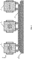
- FIG .2 is a schematic diagram of a selective laser sintering (SLS) system for manufacturing a complex object according to one embodiment of the disclosure. As shown in FIG. 2 , the system comprises a SLS device, a powder cleaning device 2, and a curing-carbonization device 3.
- SLS selective laser sintering
- the horizontal driving mechanism of the SLS device comprises two guide rails 6 disposed on both sides of the support platform; the guide rails 6 are disposed on the ground 115; the SLS device 1, the powder cleaning device 2 and the curing-carbonization device 3 each comprises a plurality of pulleys 113 that cooperates with the guide rail 6 to work; the SLS device, the powder cleaning device and the curing-carbonization device slide on the guide rails 6; and the object on the support platform are sequentially subjected to the powder sintering, powder removal and curing-carbonization.
- FIG. 3 is a top view of a powder cleaning device according to one embodiment of the disclosure.
- the powder cleaning device 2 comprises a chamber 25, and a rotating rail 23, an air outlet 21 and an air inlet 22.
- the air inlet are disposed in the chamber; and the air outlet and the air inlet are disposed on the rotating rail; when the powder cleaning device 2 is moved over the building platform, the building platform is located in the center of the rotating rail of the chamber 25, and the door 24 of the chamber is thus closed; the air outlet and the air inlet rotate on the rotating rail and cooperate with each other, to clean the powder covered on the green part by blowing and suction from 360 degrees.
- the powder cleaning device 2 slides via the guide rails 6, which make the powder cleaning device move to the support platform without moving the support platform; the powder cleaning device has an powder air outlet and an powder air inlet, as well as the powder air outlet is opposite to the powder air inlet and both simultaneously work; the powder blowing and powder suction equipment can be rotated at 360 degrees to achieve omnibearing powder blowing and powder suction, improving the quality of cleaning the powder.
- FIG. 4 is a top view of a curing-carbonization device according to one embodiment of the disclosure.
- the curing-carbonization device 3 comprises a sealed chamber 30 and a heating mechanism 33, and a sealed layer 32 is disposed in the sealed chamber 30 and is configure to seal the parts on the forming table; and the curing-carbonization device is moved over the building mechanism to close the door 31 of the sealed chamber; the heating mechanism 33 is disposed to surround the support platform and is configure to heat and cure the shaped object; an intake pipe 34 and an exhaust pipe 35 is disposed in the sealed chamber 30, maintaining the vacuum or inert gas in the sealed chamber 30; the intake pipe 34 is configured to discharge the inert gas, and the exhaust pipe 35 is responsible for vacuuming and exhaust the gas.
- the curing-carbonization device 3 slides on the guide rail 6, which make the curing-carbonization device move to the support platform without moving the support platform; the curing-carbonization device 3 has a front furnace door and a rear furnace door along the direction of the guide rails 6, which realizes the sealed treatment of the object; the curing-carbonization device 3 is cured by heating, and the heating mechanism can heat the parts up to 1000°C, and then cure the shaped object.
- FIG. 5 is a flow diagram of a method of manufacturing a complex object according to one embodiment of the disclosure.
- a method for manufacturing a large-size and complex SiC ceramic object is summarized as follows:
- the SLS device slides on the upper surface of the support platform 110 via the guide rails 6 and the pulleys 113; the plurality of powder cylinders 16 and the powder distributing roller are fixed on the SLS device and are quantitatively lifted along with the SLS device by a vertical driving mechanism 112 supported on the guide rails, realizing a quantitative rise of the powder bed; the groove 17 is fixed on the upper surface of the support platform 110, and the sidewall of the groove is synchronously raised by the lifting mechanism 111 with the rise of the powder bed; the SLS device comprises a plurality of lasers and oscillating mirrors which cooperate to complete a rapid and high-quality manufacturing of a large-size object; the SLS device 1 employs a big data processing software and hardware to plan a multi-laser scanning path.
- the SLS device 1 is removed along the guide rails 6 after sintering the powder, and the powder cleaning device 2 slides on the upper surface of the support platform; the sidewall 18 of the groove 17 moves down under the control of the lifting mechanism 111; the air outlet 21 and the air inlet 22 are opened, and the guide rails 23 start to rotate to complete a 360-degree rotation cleaning.
- the powder cleaning device 2 is removed via the guide rails 6, and the curing-carbonization device 3 slides to the upper surface of the support platform.
- the furnace door 4 of the curing-carbonization device is closed to form a sealed environment, and the formed object is heated to cure.
- the sealed layer of the curing-carbonization device is sealed after finishing the curing; the exhaust pipe 35 is responsible for vacuuming, and an inert gas is introduced from the intake pipe 34; the heating mechanism heats the parts up to 600-1500°C in a vacuum or an inert gas atmosphere for manufacturing a large-size and complex carbon preform.
- the carbon preform obtained in (4) is siliconized to yield a large-size and complex SiC ceramic object.
- the support platform is a square with a side length of 1 m to 10 m; the groove is fixed on the upper surface of the support platform, and the sidewall of the groove is lifted via the lifting mechanism by a maximum height of 10 m.
- the SLS device has a maximum lifting height of 10 m by the vertical driving mechanism.
- the inert gas described in (4) comprises nitrogen and argon; and the temperature for carbonization is 600-1500°C.
- the siliconizing method described in (4) comprises a precursor-infiltration-pyrolysis method, a chemical vapor infiltration method, and a reaction melt infiltration method (including liquid and vapor silicon infiltration).
Landscapes
- Chemical & Material Sciences (AREA)
- Engineering & Computer Science (AREA)
- Materials Engineering (AREA)
- Manufacturing & Machinery (AREA)
- Mechanical Engineering (AREA)
- Physics & Mathematics (AREA)
- Optics & Photonics (AREA)
- Ceramic Engineering (AREA)
- Organic Chemistry (AREA)
- Inorganic Chemistry (AREA)
- Structural Engineering (AREA)
- Chemical Kinetics & Catalysis (AREA)
- General Chemical & Material Sciences (AREA)
- Metallurgy (AREA)
- Powder Metallurgy (AREA)
- Producing Shaped Articles From Materials (AREA)
Abstract
Description
- The present invention relates to the field of additive manufacturing, and more particularly to a selective laser sintering (SLS) device for manufacturing complex parts.
- Additive manufacturing processes allow a build up of a three-dimensional objects from a computer-aided design (CAD) model, usually by successively adding a material layer by layer, which is also known as additive manufacturing. One of the key advantages of additive manufacturing is the ability to produce complex shapes or geometries. A prerequisite for producing a 3D printed object is a digital 3D model or a CAD file.
- Conventionally, the operation platform of the selective laser sintering devices for additive manufacturing is relatively small and cannot be used tp produce large-sized complex parts. The manufacturing of complex parts also conventionally involves a plurality of steps and a manual assembly. This increases the likelyhood of structural errors and also reduces the precision and manufacturing efficiency.
- The present invention thus provides a selective laser sintering (SLS) device for manufacturing a complex object. The SLS device comprises a laser forming unit, a support platform and a driving mechanism.
- The support platform is configured to support a plurality of raw materials for additive manufacturing of an object comprising a plurality of sections. The laser forming unit is disposed on the support platform and is configured to lay or deposit, respectively, powders on a surface of each section of the object and to sinter the powders. The driving mechanism is disposed under the laser forming unit and comprises a vertical driving mechanism and a horizontal driving mechanism. The vertical driving mechanism is connected to the laser forming unit and is configured to lift the laser forming unit according to the formed layers and a height of each section of the object so that the object is processed in a vertical direction with respect to the support platform. The horizontal driving mechanism is configured to drive the laser forming unit to move in a horizonal direction with respect to the support platform so that the laser forming unit moves over the support platform or moves away from the support platform. The forming parts are kept on the support platform for subsequent processing without moving after the completion of SLS forming.
- The laser forming unit comprises a housing, two powder cylinders, a separator, a powder laying unit, a laser unit, and a plurality of heating units. The powder laying unit is disposed in the housing and comprises a plurality of powder cylinders and a roller. The plurality of powder cylinders is symmetrically disposed on both sides of the support platform. The roller is configured to move back and forth between the plurality of powder cylinders and the support platform to transport the powders in the plurality of powder cylinders to the support platform. The separator is disposed in the housing and divides the housing to a first half and a second half. Tthe lasering unit is disposed in the first half and comprises a laser and an oscillating mirror, and is further configured to emit a laser beam to sinter the powders on the support platform. The plurality of heating units is disposed in the second half and is configured to preheat the powders on the support platform prior to the sintering of the powders.
- The support platform comprises a groove to accommodate the powders suppplied from the plurality of powder cylinders. The groove comprises a sidewall adapted to move vertically with respect to the support platform.
- The housing comprises an inner wall and a thermal insulation layer attached to the inner wall.
- In another aspect, the present inventoin provides a selective laser sintering system comprising the aforesaid selective laser sintering device, a powder cleaning device, and a curing-carbonization device. The horizontal driving mechanism of the device comprises two guide rails disposed on both sides of the support platform; the selective laser sintering device, the powder cleaning device, and the curing-carbonization device each comprises a plurality of pulleys adapted to slide on the guide rails. Each device in turn carries out selective laser sintering, powder cleaning, post-curing and carbonization processes for the parts to be formed on the support platform.
- The powder cleaning device comprises a chamber, a rotating rail, an air outlet, and an air inlet. The rotating rail, the air outlet, and the air inlet are disposed in the chamber; and the air outlet and the air inlet are disposed on the rotating rail.
- The curing-carbonization device comprises a sealed chamber, an intake pipe, an exhaust pipe, and a heating mechanism disposed in the sealed chamber; and the intake pipe and the exhaust pipe are disposed on the seal chamber.
- According to another aspect of the disclosure, also provided is a method for forming a SiC ceramic object using the aforesaid system, the method comprising:
- 1) building a 3D model of an object, slicing the 3D model, and acquiring data of a plurality of section surfaces of the 3D model; employing a resin or a resin composite material as a raw material; placing the raw material in the selective laser sintering which comprises a housing, a separator, a powder laying unit, a lasering unit, and a plurality of heating units; according to the data of a plurality of section surfaces of the 3D model, laying, by the powder laying unit, powders on the support platform; preheating the powders by the plurality of heating units; sintering the powders by the lasering unit, to complete the processing of a first section of the object; lifting the selective laser sintering, processing a second section of the object; repeating the lifting and processing, to yield a green part of the object;
- 2) removing the selective laser sintering device from the support platform, moving the powder cleaning device on the support platform, opening the air outlet and the air inlet, rotating the rotating rail, to remove the powders on the green part of the object; and the green part is cleaned by rotating 360 degrees; and
- 3) removing the powder cleaning device from the support platform; moving the curing-carbonization device on the support platform, the curing-carbonization device comprising a sealed chamber and a heating mechanism, which is seamlessly connected with the sealed chamber and the support platform, and heating to cure the green part of the object by the heating mechanism; filling the sealed chamber with an inert gas or vacuumizing the sealed chamber, heating the green part to 600-1500°C to yield a carbonized preform of the object, and siliconizing the carbonized preform to obtain a SiC ceramic object.
- In 3), siliconizing the carbonized preform adopts a precursor-infiltration-pyrolysis (PIP) method, a chemical vapor infiltration (CVI) method or a reactive infiltration method.
- Advantages of the selective laser sintering device according to embodiments of the disclosure are summarized as follows:
- 1. The SLS device comprises a laser forming unit and a support platform. The support platform is fixedly disposed and the laser forming unit can move vertically with respect to the support platform. The complex object is formed layer by layer on the support platform without moving relative to the support platform, thus reducing the probability of bending, deformation, collapse, or deformation of the object, improving the product quality.
- 2. The selective laser sintering device comprises a housing and a plurality of heating units. The support platform is sealed in the housing and the raw materials is evenly preheated by the plurality of heating units prior to forming the object. In addition, through the coordination of insulation layer and heating unit, the temperature distribution in the forming cavity can be uniform, so as to avoid the warping deformation caused by uneven temperature distribution.
- 3. The SLS system for manufacturing a SiC ceramic object comprises a SLS device, a powder cleaning device, and a curing-carbonization device. The formation and processing of the object can be achieved in one step, improving the processing efficiency.
- 4. The method of forming a SiC ceramic object comprises forming a green part by SLS, powder cleaning, curing, carbonization, and siliconizing. The method can be used to manufacturing a product with any three-dimensional structure.
-
-
FIG.1 is a schematic diagram of a selective laser sintering (SLS) device for manufacturing a complex object according to one embodiment of the disclosure; -
FIG.2 is a schematic diagram of a selective laser sintering (SLS) system for manufacturing a complex object according to one embodiment of the disclosure; -
FIG.3 is a top view of a powder cleaning device according to one embodiment of the disclosure; -
FIG. 4 is a top view of a curing-carbonization device according to one embodiment of the disclosure; and -
FIG. 5 is a flow diagram of a method of manufacturing a complex object according to one embodiment of the disclosure. - In the drawings, the following reference numbers are used: 1. Selective laser sintering device; 2. Powder cleaning device; 3. Curing-carbonization device; 6. Guide rail; 10. Housing; 11. Laser; 12. Oscillating mirror; 13. Thermal insulating layer; 14. Heating unit; 15. Roller; 16. Powder cylinder; 17. Groove; 18. Sidewall; 19. Formed blank; 20. Separator; 21. Air outlet; 22. Air inlet; 23. Rotating rail; 24. Door of chamber; 25. Chamber; 30. Sealed chamber; 31. Door of sealed chamber; 32. Sealed layer; 33. Heating mechanism; 34. Intake pipe; 35. Exhaust pipe; 110. Support platform; 111. Lifting mechanism; 112. Vertical driving mechanism; 113. Pulley; 115. Ground.
- To further illustrate, embodiments detailing a selective laser sintering device for manufacturing a complex object are described below. It should be noted that the following embodiments are intended to describe and not to limit the disclosure.
- The disclosure provides a SLS device for manufacturing a large-size and complex object, and a SLS system and a method thereof. The SLS system comprises a SLS device comprising a support platform, a powder cleaning device, and a curing-carbonization device. The support platform is unmovable and the raw materials are processed on the support platform. The SLS device comprises a laser forming unit, a plurality of lasers and oscillating mirrors for producing a blank of an object. The powder cleaning device and the curing-carbonization device can slide on the guide rails of the SLS device to further process the blank of the object.
-
FIG. 1 is a schematic diagram of a SLS device for manufacturing a large-size and complex object according to one embodiment of the disclosure. As shown inFIG. 1 , the SLS device comprises a laser forming unit, a support platform and a driving mechanism; the support platform is a platform for forming an object, the laser forming unit is disposed on the support platform and is configured to lay powder on the section surface of the object and sinter the powders; the driving mechanism is disposed under the laser forming unit and comprises a vertical driving mechanism and a horizontal driving mechanism. After the laser forming unit completes a SLS process on one section surface on the support platform, the vertical driving mechanism lifts the laser forming unit layer by layer according to the height of each section of the object so that the object is processed in a vertical direction with respect to the support platform, which avoids up and down movement of the parts due to a moving support platform. And the horizontal driving mechanism is configured to drive the laser forming unit to move in a horizontal direction with respect to the support platform so that the laser forming unit moves over the support platform or separates from the support platform, avoiding moving the parts in subsequent processing. - The SLS device comprises a
housing 10 and a powder laying unit; the powder laying unit is disposed in the housing and comprises a plurality ofpowder cylinders 16 and aroller 15; the plurality ofpowder cylinders 16 is symmetrically disposed on the both sides of the support platform; theroller 15 moves back and forth between the plurality of powder cylinders and the support platform, so that the powder brought from the plurality ofpowder cylinders 16 is evenly laid on the support platform; thehousing 10 is internally provided with aseparator 20, the inner space of the separator is divided into a first half and a second half; the first half comprises a laser configured to emit a laser sinter the powder on the support platform. The second half as a forming cavity for the parts, internally provided with a plurality of uniformly distributedheating units 14, aiming to preheat the powder on the support platform prior to the sintering of the powders. - A plurality of laser units and
heating units 14 are disposed in the housing; the laser unit each comprises alaser 11 and anoscillating mirror 12. In this embodiment, 3x3 sets of laser units are disposed for manufacturing the parts of about 5 meters; the powder on the support platform is preheated byheating units 14 prior to the sintering of the powders; the heating method may be resistance heating and radiant heating; a thermal insulatinglayer 13 is deposited in the housing, and the temperature is evenly distributed in the forming cavity to uniformly preheat the powder; and the temperature distribution in the forming cavity is evenly distributed to uniformly preheat the powder; theseparator 20 is disposed in the housing and separates the laser unit from the forming cavity to prevent the laser from overheating. - The SLS device adopts two methods of powder supply including falling powder and laying powder; the plurality of powder cylinders is fixed on the laser forming unit; the heating is disposed in the plurality of powder cylinders and is configured to preheat the powder; the roller is quantitatively lifted along with the
SLS device 1 by avertical driving mechanism 112 supported on the guide rails, realizing a quantitative rise of the powder bed; theSLS device 1 comprises a plurality of lasers and oscillating mirrors which cooperate to complete a rapid and high-quality forming of a large-size object; theSLS device 1 employs a large amount of data processing software and hardware to plan a multi-laser scanning path; a horizontal driving mechanism is disposed under the laser forming unit; the horizontal driving mechanism comprises aguide rail 6 which is disposed under the laser forming unit and cooperates with thepulleys 113; the laser forming unit can be moved to or removed from the support platform by sliding on theguide rail 6. - The support platform comprises a
groove 17, and the powder is spread across thegroove 17; after one section surface is formed, the sidewall of the groove lifts the height of a single section surface, avoiding the powder spilled from the groove scattering over other area; the formed blank 19 is in thegroove 17; thelifting mechanism 111 on the sidewall rises along with thevertical driving mechanism 112 of the laser forming unit. -
FIG.2 is a schematic diagram of a selective laser sintering (SLS) system for manufacturing a complex object according to one embodiment of the disclosure. As shown inFIG. 2 , the system comprises a SLS device, apowder cleaning device 2, and a curing-carbonization device 3. The horizontal driving mechanism of the SLS device comprises twoguide rails 6 disposed on both sides of the support platform; theguide rails 6 are disposed on theground 115; theSLS device 1, thepowder cleaning device 2 and the curing-carbonization device 3 each comprises a plurality ofpulleys 113 that cooperates with theguide rail 6 to work; the SLS device, the powder cleaning device and the curing-carbonization device slide on theguide rails 6; and the object on the support platform are sequentially subjected to the powder sintering, powder removal and curing-carbonization. -
FIG. 3 is a top view of a powder cleaning device according to one embodiment of the disclosure. As shown inFIG. 3 , thepowder cleaning device 2 comprises achamber 25, and a rotatingrail 23, anair outlet 21 and anair inlet 22. The air inlet are disposed in the chamber; and the air outlet and the air inlet are disposed on the rotating rail; when thepowder cleaning device 2 is moved over the building platform, the building platform is located in the center of the rotating rail of thechamber 25, and thedoor 24 of the chamber is thus closed; the air outlet and the air inlet rotate on the rotating rail and cooperate with each other, to clean the powder covered on the green part by blowing and suction from 360 degrees. - The
powder cleaning device 2 slides via theguide rails 6, which make the powder cleaning device move to the support platform without moving the support platform; the powder cleaning device has an powder air outlet and an powder air inlet, as well as the powder air outlet is opposite to the powder air inlet and both simultaneously work; the powder blowing and powder suction equipment can be rotated at 360 degrees to achieve omnibearing powder blowing and powder suction, improving the quality of cleaning the powder. -
FIG. 4 is a top view of a curing-carbonization device according to one embodiment of the disclosure. As shown inFIG. 4 , the curing-carbonization device 3 comprises a sealedchamber 30 and aheating mechanism 33, and a sealedlayer 32 is disposed in the sealedchamber 30 and is configure to seal the parts on the forming table; and the curing-carbonization device is moved over the building mechanism to close thedoor 31 of the sealed chamber; theheating mechanism 33 is disposed to surround the support platform and is configure to heat and cure the shaped object; anintake pipe 34 and anexhaust pipe 35 is disposed in the sealedchamber 30, maintaining the vacuum or inert gas in the sealedchamber 30; theintake pipe 34 is configured to discharge the inert gas, and theexhaust pipe 35 is responsible for vacuuming and exhaust the gas. - The curing-
carbonization device 3 slides on theguide rail 6, which make the curing-carbonization device move to the support platform without moving the support platform; the curing-carbonization device 3 has a front furnace door and a rear furnace door along the direction of theguide rails 6, which realizes the sealed treatment of the object; the curing-carbonization device 3 is cured by heating, and the heating mechanism can heat the parts up to 1000°C, and then cure the shaped object. -
FIG. 5 is a flow diagram of a method of manufacturing a complex object according to one embodiment of the disclosure. A method for manufacturing a large-size and complex SiC ceramic object is summarized as follows: - The SLS device slides on the upper surface of the
support platform 110 via theguide rails 6 and thepulleys 113; the plurality ofpowder cylinders 16 and the powder distributing roller are fixed on the SLS device and are quantitatively lifted along with the SLS device by avertical driving mechanism 112 supported on the guide rails, realizing a quantitative rise of the powder bed; thegroove 17 is fixed on the upper surface of thesupport platform 110, and the sidewall of the groove is synchronously raised by thelifting mechanism 111 with the rise of the powder bed; the SLS device comprises a plurality of lasers and oscillating mirrors which cooperate to complete a rapid and high-quality manufacturing of a large-size object; theSLS device 1 employs a big data processing software and hardware to plan a multi-laser scanning path. - The
SLS device 1 is removed along theguide rails 6 after sintering the powder, and thepowder cleaning device 2 slides on the upper surface of the support platform; thesidewall 18 of thegroove 17 moves down under the control of thelifting mechanism 111; theair outlet 21 and theair inlet 22 are opened, and the guide rails 23 start to rotate to complete a 360-degree rotation cleaning. - Following the powder removal process, the
powder cleaning device 2 is removed via theguide rails 6, and the curing-carbonization device 3 slides to the upper surface of the support platform. Thefurnace door 4 of the curing-carbonization device is closed to form a sealed environment, and the formed object is heated to cure. - The sealed layer of the curing-carbonization device is sealed after finishing the curing; the
exhaust pipe 35 is responsible for vacuuming, and an inert gas is introduced from theintake pipe 34; the heating mechanism heats the parts up to 600-1500°C in a vacuum or an inert gas atmosphere for manufacturing a large-size and complex carbon preform. - The carbon preform obtained in (4) is siliconized to yield a large-size and complex SiC ceramic object.
- Preferably, in 1), the support platform is a square with a side length of 1 m to 10 m; the groove is fixed on the upper surface of the support platform, and the sidewall of the groove is lifted via the lifting mechanism by a maximum height of 10 m.
- Preferably, the SLS device has a maximum lifting height of 10 m by the vertical driving mechanism.
- Preferably, the inert gas described in (4) comprises nitrogen and argon; and the temperature for carbonization is 600-1500°C.
- Preferably, the siliconizing method described in (4) comprises a precursor-infiltration-pyrolysis method, a chemical vapor infiltration method, and a reaction melt infiltration method (including liquid and vapor silicon infiltration).
- It will be obvious to those skilled in the art that changes and modifications may be made, and therefore, the aim in the appended claims is to cover all such changes and modifications.
Claims (14)
- A selective laser sintering device, comprising:1) a laser forming unit;2) a support platform; and3) a driving mechanism;wherein:the support platform is configured to support a plurality of raw materials for additive manufacturing of an object comprising a plurality of sections;the laser forming unit is disposed on the support platform and is configured to lay powders on a surface of each section of the object and sinter the powders;the driving mechanism is disposed under the laser forming unit and comprises a vertical driving mechanism and a horizontal driving mechanism;the vertical driving mechanism is connected to the laser forming unit and configured to lift the laser forming unit layer by layer according to a height of each section of the object so that the object is processed in a vertical direction with respect to the support platform; andthe horizontal driving mechanism is configured to drive the laser forming unit to move in a horizonal direction with respect to the support platform so that the laser forming unit moves over the support platform or separates from the support platform.
- The device of claim 1, wherein the laser forming unit comprises a housing, a separator, a powder laying unit, a lasering unit, and a plurality of heating units; the powder laying unit is disposed in the housing and comprises a plurality of powder cylinders and a roller; the plurality of powder cylinders is symmetrically disposed on both sides of the support platform; the roller is configured to move back and forth between the plurality of powder cylinders and the support platform to bring powders in the plurality of powder cylinders to the support platform; the separator is disposed in the housing and divides the housing to a first half and a second half; the lasering unit is disposed in the first half, comprises a laser and an oscillating mirror, and is configured to emit a laser to sinter the powders on the support platform; the plurality of heating units is disposed in the second half and is configured to preheat the powders on the support platform prior to the sintering of the powders.
- The device of claim 1, wherein the support platform comprises a groove to accommodate the powders brought from the plurality of powder cylinders; the groove comprises a sidewall adapted to move vertically with respect to the support platform.
- The device of claim 2, wherein the support platform comprises a groove to accommodate the powders brought from the plurality of powder cylinders; the groove comprises a sidewall adapted to move vertically with respect to the support platform.
- The device of claim 1, wherein the housing comprises an inner wall and a thermal insulation layer attached to the inner wall.
- The device of claim 2, wherein the housing comprises an inner wall and a thermal insulation layer attached to the inner wall.
- The device of claim 3, wherein the housing comprises an inner wall and a thermal insulation layer attached to the inner wall.
- The device of claim 4, wherein the housing comprises an inner wall and a thermal insulation layer attached to the inner wall.
- A system, comprising a device of any of claims 1 to 8, a powder cleaning device, and a curing-carbonization device; wherein the horizontal driving mechanism of the device comprises two guide rails disposed on both sides of the support platform; the device, the powder cleaning device, and the curing-carbonization device each comprises a plurality of pulleys adapted to slide on the guide rails.
- The system of claim 9, wherein the powder cleaning device comprises a chamber, a rotating rail, an air outlet, and an air inlet; the rotating rail, the air outlet, and the air inlet are disposed in the chamber; and the air outlet and the air inlet are disposed on the rotating rail.
- The system of claim 9, wherein the curing-carbonization device comprises a sealed chamber, an intake pipe, an exhaust pipe, and a heating mechanism disposed in the sealed chamber; and the intake pipe and the exhaust pipe are disposed on the seal chamber.
- The system of claim 10, wherein the curing-carbonization device comprises a sealed chamber, an intake pipe, an exhaust pipe, and a heating mechanism disposed in the sealed chamber; and the intake pipe and the exhaust pipe are disposed on the seal chamber.
- A method of forming an object using the system of any of claims 9 - 12, comprising:1) building a 3D model of an object, slicing the 3D model, and acquiring data of a plurality of section surfaces of the 3D model; employing a resin or a resin composite material as a raw material; placing the raw material in the laser forming unit comprising a housing, a separator, a powder laying unit, a lasering unit, and a plurality of heating units; according to the data of a plurality of section surfaces of the 3D model, laying, by the powder laying unit, powders on the support platform; preheating the powders by the plurality of heating units; sintering the powders by the lasering unit, to complete the processing of a first section of the object; lifting the laser forming unit, processing a second section of the object; repeating the lifting and processing, to yield a green part of the object;2) removing the SLS device from the support platform, moving the powder cleaning device on the support platform, opening the air outlet and the air inlet, rotating the rotating rail, to remove the powders on the green part of the object; and3) removing the powder cleaning device from the support platform; moving the curing-carbonization device on the support platform, the curing-carbonization device comprising a sealed chamber and a heating mechanism, seamlessly connecting the sealed chamber and the support platform, and heating to cure the green part of the object by the heating mechanism; filling the sealed chamber with an inert gas or vacuumizing the sealed chamber, heating the green part to 600-1500°C to yield a carbonized preform of the object, and siliconizing the carbonized preform to obtain a SiC ceramic object.
- The method of claim 13, wherein in 3), siliconizing the carbonized preform adopts a precursor-infiltration-pyrolysis (PIP) method, a chemical vapor infiltration (CVI) method or a reactive infiltration method.
Applications Claiming Priority (1)
| Application Number | Priority Date | Filing Date | Title |
|---|---|---|---|
| CN201910447966.2A CN110194669B (en) | 2019-05-27 | 2019-05-27 | A laser selective sintering forming equipment, system and method for large and complex parts |
Publications (2)
| Publication Number | Publication Date |
|---|---|
| EP3744506A1 true EP3744506A1 (en) | 2020-12-02 |
| EP3744506B1 EP3744506B1 (en) | 2022-06-22 |
Family
ID=67753099
Family Applications (1)
| Application Number | Title | Priority Date | Filing Date |
|---|---|---|---|
| EP19207048.0A Active EP3744506B1 (en) | 2019-05-27 | 2019-11-05 | Selective laser sintering device |
Country Status (5)
| Country | Link |
|---|---|
| US (1) | US11305456B2 (en) |
| EP (1) | EP3744506B1 (en) |
| JP (1) | JP6896817B2 (en) |
| CN (1) | CN110194669B (en) |
| RU (1) | RU2745247C1 (en) |
Families Citing this family (10)
| Publication number | Priority date | Publication date | Assignee | Title |
|---|---|---|---|---|
| WO2019083493A1 (en) * | 2017-10-23 | 2019-05-02 | Hewlett-Packard Development Company, L.P. | Forming a layer of build material |
| KR102317286B1 (en) * | 2019-06-07 | 2021-10-26 | 울산대학교 산학협력단 | Method of manufacturing metal mold using the 3D printing |
| CN110919819B (en) * | 2019-12-20 | 2020-09-18 | 华中科技大学 | Additive manufacturing equipment and method based on multi-field compounding |
| CN111268411B (en) * | 2020-01-23 | 2021-07-20 | 华东理工大学 | A table transfer transportation system for large-scale SLM equipment |
| CN112008077A (en) * | 2020-08-04 | 2020-12-01 | 西安铂力特增材技术股份有限公司 | A large-scale SLM device that saves metal powder |
| CN114247901B (en) * | 2021-12-17 | 2024-02-27 | 福建国锐中科光电有限公司 | Metal 3D printing and post-treatment integrated forming equipment and printing method |
| CN114799207B (en) * | 2022-03-31 | 2024-04-12 | 西安航天发动机有限公司 | Forming method of complex prefabricated member of metal perspiration material |
| CN117282992A (en) * | 2022-06-16 | 2023-12-26 | 上海飞机制造有限公司 | Equipment for treating splashed powder in additive manufacturing process of metal powder |
| CN115648620B (en) * | 2022-11-07 | 2026-03-06 | 西安交通大学 | A high-throughput molding apparatus and molding method suitable for adhesive spraying |
| CN116512378B (en) * | 2023-04-10 | 2025-07-22 | 东南大学 | Ceramic multi-material integrated additive manufacturing and forming system and method |
Citations (1)
| Publication number | Priority date | Publication date | Assignee | Title |
|---|---|---|---|---|
| WO2018172092A1 (en) * | 2017-03-24 | 2018-09-27 | SLM Solutions Group AG | Device and method for producing three-dimensional workpieces |
Family Cites Families (18)
| Publication number | Priority date | Publication date | Assignee | Title |
|---|---|---|---|---|
| US7034246B2 (en) * | 2004-08-10 | 2006-04-25 | The Boeing Company | Selective laser sintering reduced volume feed mechanism |
| RU137490U1 (en) * | 2013-07-16 | 2014-02-20 | Федеральное государственное бюджетное образовательное учреждение высшего профессионального образования "Московский государственный технологический университет "СТАНКИН" (ФГБОУ ВПО МГТУ "СТАНКИН") | DEVICE FOR SELECTIVE LASER SINTERING OF PREPARATIONS OF POWDER MATERIALS |
| CN104425123A (en) * | 2013-09-05 | 2015-03-18 | 爱科科技有限公司 | Sintering molding device and method for selective laser of rare earth permanent magnet device |
| JP6503375B2 (en) * | 2014-05-08 | 2019-04-17 | ストラタシス リミテッド | Method and apparatus for 3D printing by selective sintering |
| RU148163U1 (en) * | 2014-06-09 | 2014-11-27 | Общество с ограниченной ответственностью "НПЦ "АЛЬФА" | DEVICE FOR SELECTIVE LASER POWDER SINTERING USING LASER RADIATION |
| JP6651754B2 (en) * | 2014-09-18 | 2020-02-19 | Toto株式会社 | Method for producing reaction sintered silicon carbide member |
| US10799952B2 (en) * | 2015-06-04 | 2020-10-13 | The Regents Of The University Of California | Selective laser sintering using functional inclusions dispersed in the matrix material being created |
| CN105127422A (en) * | 2015-09-06 | 2015-12-09 | 苏州西帝摩三维打印科技有限公司 | Multifunctional forming workbench for selective laser melting |
| US11691341B2 (en) * | 2015-10-30 | 2023-07-04 | Seurat Technologies, Inc. | Part manipulation using printed manipulation points |
| CN105563845A (en) * | 2015-11-06 | 2016-05-11 | 仲炳华 | 3D (three-dimensional) laser printer |
| JP6477428B2 (en) * | 2015-11-09 | 2019-03-06 | トヨタ自動車株式会社 | Control method of additive manufacturing apparatus |
| WO2018005439A1 (en) * | 2016-06-29 | 2018-01-04 | Velo3D, Inc. | Three-dimensional printing and three-dimensional printers |
| CN106187195B (en) * | 2016-06-29 | 2018-11-30 | 华中科技大学 | The method that silicon carbide ceramics are prepared using selective laser sintering technique |
| CN206415600U (en) * | 2016-12-22 | 2017-08-18 | 华南理工大学 | Melt high efficiency forming device in a kind of selective laser |
| CN206588344U (en) * | 2017-03-20 | 2017-10-27 | 西安科技大学 | A kind of SLS moulding cylinders powder dumping device |
| US11654490B2 (en) * | 2017-04-18 | 2023-05-23 | Hewlett-Packard Development Company, L.P. | Apparatus having a movable chamber |
| DE102017208496A1 (en) * | 2017-05-19 | 2018-11-22 | SLM Solutions Group AG | Apparatus and method for producing three-dimensional workpieces |
| CN207615658U (en) * | 2017-11-23 | 2018-07-17 | 韶关学院 | A kind of selective laser fusing 3D printing power spreading device |
-
2019
- 2019-05-27 CN CN201910447966.2A patent/CN110194669B/en active Active
- 2019-09-26 JP JP2019175174A patent/JP6896817B2/en active Active
- 2019-10-16 US US16/655,215 patent/US11305456B2/en active Active
- 2019-11-05 EP EP19207048.0A patent/EP3744506B1/en active Active
- 2019-12-11 RU RU2019140946A patent/RU2745247C1/en active
Patent Citations (1)
| Publication number | Priority date | Publication date | Assignee | Title |
|---|---|---|---|---|
| WO2018172092A1 (en) * | 2017-03-24 | 2018-09-27 | SLM Solutions Group AG | Device and method for producing three-dimensional workpieces |
Also Published As
| Publication number | Publication date |
|---|---|
| JP6896817B2 (en) | 2021-06-30 |
| JP2020192800A (en) | 2020-12-03 |
| US11305456B2 (en) | 2022-04-19 |
| US20200376708A1 (en) | 2020-12-03 |
| EP3744506B1 (en) | 2022-06-22 |
| RU2745247C1 (en) | 2021-03-22 |
| CN110194669B (en) | 2020-11-24 |
| CN110194669A (en) | 2019-09-03 |
Similar Documents
| Publication | Publication Date | Title |
|---|---|---|
| EP3744506B1 (en) | Selective laser sintering device | |
| US11046066B2 (en) | Additive manufacturing apparatus and method | |
| EP3137284B1 (en) | Production line for making tangible products by layerwise manufacturing | |
| US10029308B2 (en) | Three dimensional printer | |
| CN109807329B (en) | A method for high-power laser selective melting of 3D printing high-speed rail brake discs | |
| US20100040992A1 (en) | Ascending/descending apparatus and complex sintering furnace using the same | |
| CN107810073A (en) | Additive Manufacturing with Temperature Control | |
| RU2550670C2 (en) | Production of metal article by laser cyclic application of powder and unit to this end | |
| JP2019077935A (en) | Three-dimensional molding device and method for manufacturing three-dimensional molded object | |
| KR20180111860A (en) | METHOD FOR PRODUCING SEMICONDUCTOR SEMICONDUCTOR, AND METHOD AND APPARATUS FOR MANUFACTURING CERAMIC PRODUCTS | |
| JP3147744B2 (en) | Lamination molding method of sand mold and method of manufacturing casting using the same | |
| CN1301224C (en) | Press forming device and forming method of optical element | |
| JP7723066B2 (en) | Apparatus and method for managing temperature and stress in parts during additive manufacturing | |
| KR102290893B1 (en) | Laser sintering apparatus capable of continously laser sintering | |
| JP4771270B2 (en) | Method and apparatus for replacing glass plate mold | |
| CN100413796C (en) | Method for continuously producing decorative veneer panels, device for carrying out said method and decorative covering material | |
| CN108778576B (en) | Method for manufacturing three-dimensional shaped object | |
| TW201313627A (en) | Molding device and molding method for glass casings | |
| RU2717761C1 (en) | Apparatus for selective laser sintering and method of producing large-size articles on said apparatus | |
| CN119194377A (en) | ITO rotary target material degreasing tool and degreasing method thereof | |
| KR100826268B1 (en) | Rotary Furnaces and Plasticizing Systems for Manufacturing Ceramic Electronic Components | |
| CN117561149A (en) | Products containing silicon carbide as a main component and manufacturing methods thereof | |
| CN120790952A (en) | Micro-forging rolling composite additive manufacturing method | |
| CN117597208A (en) | Sand molding for metal additive casting | |
| CN116847973A (en) | Additive manufacturing method for continuous manufacturing of shaped bodies and corresponding device |
Legal Events
| Date | Code | Title | Description |
|---|---|---|---|
| PUAI | Public reference made under article 153(3) epc to a published international application that has entered the european phase |
Free format text: ORIGINAL CODE: 0009012 |
|
| STAA | Information on the status of an ep patent application or granted ep patent |
Free format text: STATUS: REQUEST FOR EXAMINATION WAS MADE |
|
| 17P | Request for examination filed |
Effective date: 20191105 |
|
| AK | Designated contracting states |
Kind code of ref document: A1 Designated state(s): AL AT BE BG CH CY CZ DE DK EE ES FI FR GB GR HR HU IE IS IT LI LT LU LV MC MK MT NL NO PL PT RO RS SE SI SK SM TR |
|
| AX | Request for extension of the european patent |
Extension state: BA ME |
|
| GRAP | Despatch of communication of intention to grant a patent |
Free format text: ORIGINAL CODE: EPIDOSNIGR1 |
|
| STAA | Information on the status of an ep patent application or granted ep patent |
Free format text: STATUS: GRANT OF PATENT IS INTENDED |
|
| INTG | Intention to grant announced |
Effective date: 20220110 |
|
| GRAS | Grant fee paid |
Free format text: ORIGINAL CODE: EPIDOSNIGR3 |
|
| GRAA | (expected) grant |
Free format text: ORIGINAL CODE: 0009210 |
|
| STAA | Information on the status of an ep patent application or granted ep patent |
Free format text: STATUS: THE PATENT HAS BEEN GRANTED |
|
| AK | Designated contracting states |
Kind code of ref document: B1 Designated state(s): AL AT BE BG CH CY CZ DE DK EE ES FI FR GB GR HR HU IE IS IT LI LT LU LV MC MK MT NL NO PL PT RO RS SE SI SK SM TR |
|
| REG | Reference to a national code |
Ref country code: GB Ref legal event code: FG4D |
|
| REG | Reference to a national code |
Ref country code: CH Ref legal event code: EP |
|
| REG | Reference to a national code |
Ref country code: DE Ref legal event code: R096 Ref document number: 602019016118 Country of ref document: DE |
|
| REG | Reference to a national code |
Ref country code: AT Ref legal event code: REF Ref document number: 1499505 Country of ref document: AT Kind code of ref document: T Effective date: 20220715 |
|
| REG | Reference to a national code |
Ref country code: IE Ref legal event code: FG4D |
|
| REG | Reference to a national code |
Ref country code: LT Ref legal event code: MG9D |
|
| REG | Reference to a national code |
Ref country code: NL Ref legal event code: MP Effective date: 20220622 |
|
| PG25 | Lapsed in a contracting state [announced via postgrant information from national office to epo] |
Ref country code: SE Free format text: LAPSE BECAUSE OF FAILURE TO SUBMIT A TRANSLATION OF THE DESCRIPTION OR TO PAY THE FEE WITHIN THE PRESCRIBED TIME-LIMIT Effective date: 20220622 Ref country code: NO Free format text: LAPSE BECAUSE OF FAILURE TO SUBMIT A TRANSLATION OF THE DESCRIPTION OR TO PAY THE FEE WITHIN THE PRESCRIBED TIME-LIMIT Effective date: 20220922 Ref country code: LT Free format text: LAPSE BECAUSE OF FAILURE TO SUBMIT A TRANSLATION OF THE DESCRIPTION OR TO PAY THE FEE WITHIN THE PRESCRIBED TIME-LIMIT Effective date: 20220622 Ref country code: HR Free format text: LAPSE BECAUSE OF FAILURE TO SUBMIT A TRANSLATION OF THE DESCRIPTION OR TO PAY THE FEE WITHIN THE PRESCRIBED TIME-LIMIT Effective date: 20220622 Ref country code: GR Free format text: LAPSE BECAUSE OF FAILURE TO SUBMIT A TRANSLATION OF THE DESCRIPTION OR TO PAY THE FEE WITHIN THE PRESCRIBED TIME-LIMIT Effective date: 20220923 Ref country code: FI Free format text: LAPSE BECAUSE OF FAILURE TO SUBMIT A TRANSLATION OF THE DESCRIPTION OR TO PAY THE FEE WITHIN THE PRESCRIBED TIME-LIMIT Effective date: 20220622 Ref country code: BG Free format text: LAPSE BECAUSE OF FAILURE TO SUBMIT A TRANSLATION OF THE DESCRIPTION OR TO PAY THE FEE WITHIN THE PRESCRIBED TIME-LIMIT Effective date: 20220922 |
|
| REG | Reference to a national code |
Ref country code: AT Ref legal event code: MK05 Ref document number: 1499505 Country of ref document: AT Kind code of ref document: T Effective date: 20220622 |
|
| PG25 | Lapsed in a contracting state [announced via postgrant information from national office to epo] |
Ref country code: RS Free format text: LAPSE BECAUSE OF FAILURE TO SUBMIT A TRANSLATION OF THE DESCRIPTION OR TO PAY THE FEE WITHIN THE PRESCRIBED TIME-LIMIT Effective date: 20220622 Ref country code: LV Free format text: LAPSE BECAUSE OF FAILURE TO SUBMIT A TRANSLATION OF THE DESCRIPTION OR TO PAY THE FEE WITHIN THE PRESCRIBED TIME-LIMIT Effective date: 20220622 |
|
| PG25 | Lapsed in a contracting state [announced via postgrant information from national office to epo] |
Ref country code: NL Free format text: LAPSE BECAUSE OF FAILURE TO SUBMIT A TRANSLATION OF THE DESCRIPTION OR TO PAY THE FEE WITHIN THE PRESCRIBED TIME-LIMIT Effective date: 20220622 |
|
| PG25 | Lapsed in a contracting state [announced via postgrant information from national office to epo] |
Ref country code: SM Free format text: LAPSE BECAUSE OF FAILURE TO SUBMIT A TRANSLATION OF THE DESCRIPTION OR TO PAY THE FEE WITHIN THE PRESCRIBED TIME-LIMIT Effective date: 20220622 Ref country code: SK Free format text: LAPSE BECAUSE OF FAILURE TO SUBMIT A TRANSLATION OF THE DESCRIPTION OR TO PAY THE FEE WITHIN THE PRESCRIBED TIME-LIMIT Effective date: 20220622 Ref country code: RO Free format text: LAPSE BECAUSE OF FAILURE TO SUBMIT A TRANSLATION OF THE DESCRIPTION OR TO PAY THE FEE WITHIN THE PRESCRIBED TIME-LIMIT Effective date: 20220622 Ref country code: PT Free format text: LAPSE BECAUSE OF FAILURE TO SUBMIT A TRANSLATION OF THE DESCRIPTION OR TO PAY THE FEE WITHIN THE PRESCRIBED TIME-LIMIT Effective date: 20221024 Ref country code: ES Free format text: LAPSE BECAUSE OF FAILURE TO SUBMIT A TRANSLATION OF THE DESCRIPTION OR TO PAY THE FEE WITHIN THE PRESCRIBED TIME-LIMIT Effective date: 20220622 Ref country code: EE Free format text: LAPSE BECAUSE OF FAILURE TO SUBMIT A TRANSLATION OF THE DESCRIPTION OR TO PAY THE FEE WITHIN THE PRESCRIBED TIME-LIMIT Effective date: 20220622 Ref country code: CZ Free format text: LAPSE BECAUSE OF FAILURE TO SUBMIT A TRANSLATION OF THE DESCRIPTION OR TO PAY THE FEE WITHIN THE PRESCRIBED TIME-LIMIT Effective date: 20220622 Ref country code: AT Free format text: LAPSE BECAUSE OF FAILURE TO SUBMIT A TRANSLATION OF THE DESCRIPTION OR TO PAY THE FEE WITHIN THE PRESCRIBED TIME-LIMIT Effective date: 20220622 |
|
| PG25 | Lapsed in a contracting state [announced via postgrant information from national office to epo] |
Ref country code: PL Free format text: LAPSE BECAUSE OF FAILURE TO SUBMIT A TRANSLATION OF THE DESCRIPTION OR TO PAY THE FEE WITHIN THE PRESCRIBED TIME-LIMIT Effective date: 20220622 Ref country code: IS Free format text: LAPSE BECAUSE OF FAILURE TO SUBMIT A TRANSLATION OF THE DESCRIPTION OR TO PAY THE FEE WITHIN THE PRESCRIBED TIME-LIMIT Effective date: 20221022 |
|
| REG | Reference to a national code |
Ref country code: DE Ref legal event code: R097 Ref document number: 602019016118 Country of ref document: DE |
|
| PG25 | Lapsed in a contracting state [announced via postgrant information from national office to epo] |
Ref country code: AL Free format text: LAPSE BECAUSE OF FAILURE TO SUBMIT A TRANSLATION OF THE DESCRIPTION OR TO PAY THE FEE WITHIN THE PRESCRIBED TIME-LIMIT Effective date: 20220622 |
|
| PG25 | Lapsed in a contracting state [announced via postgrant information from national office to epo] |
Ref country code: DK Free format text: LAPSE BECAUSE OF FAILURE TO SUBMIT A TRANSLATION OF THE DESCRIPTION OR TO PAY THE FEE WITHIN THE PRESCRIBED TIME-LIMIT Effective date: 20220622 |
|
| PLBE | No opposition filed within time limit |
Free format text: ORIGINAL CODE: 0009261 |
|
| STAA | Information on the status of an ep patent application or granted ep patent |
Free format text: STATUS: NO OPPOSITION FILED WITHIN TIME LIMIT |
|
| 26N | No opposition filed |
Effective date: 20230323 |
|
| PG25 | Lapsed in a contracting state [announced via postgrant information from national office to epo] |
Ref country code: MC Free format text: LAPSE BECAUSE OF FAILURE TO SUBMIT A TRANSLATION OF THE DESCRIPTION OR TO PAY THE FEE WITHIN THE PRESCRIBED TIME-LIMIT Effective date: 20220622 |
|
| REG | Reference to a national code |
Ref country code: CH Ref legal event code: PL |
|
| REG | Reference to a national code |
Ref country code: BE Ref legal event code: MM Effective date: 20221130 |
|
| PG25 | Lapsed in a contracting state [announced via postgrant information from national office to epo] |
Ref country code: LI Free format text: LAPSE BECAUSE OF NON-PAYMENT OF DUE FEES Effective date: 20221130 Ref country code: CH Free format text: LAPSE BECAUSE OF NON-PAYMENT OF DUE FEES Effective date: 20221130 |
|
| PG25 | Lapsed in a contracting state [announced via postgrant information from national office to epo] |
Ref country code: SI Free format text: LAPSE BECAUSE OF FAILURE TO SUBMIT A TRANSLATION OF THE DESCRIPTION OR TO PAY THE FEE WITHIN THE PRESCRIBED TIME-LIMIT Effective date: 20220622 Ref country code: LU Free format text: LAPSE BECAUSE OF NON-PAYMENT OF DUE FEES Effective date: 20221105 |
|
| PG25 | Lapsed in a contracting state [announced via postgrant information from national office to epo] |
Ref country code: IE Free format text: LAPSE BECAUSE OF NON-PAYMENT OF DUE FEES Effective date: 20221105 |
|
| PG25 | Lapsed in a contracting state [announced via postgrant information from national office to epo] |
Ref country code: BE Free format text: LAPSE BECAUSE OF NON-PAYMENT OF DUE FEES Effective date: 20221130 |
|
| PG25 | Lapsed in a contracting state [announced via postgrant information from national office to epo] |
Ref country code: IT Free format text: LAPSE BECAUSE OF FAILURE TO SUBMIT A TRANSLATION OF THE DESCRIPTION OR TO PAY THE FEE WITHIN THE PRESCRIBED TIME-LIMIT Effective date: 20220622 |
|
| PG25 | Lapsed in a contracting state [announced via postgrant information from national office to epo] |
Ref country code: CY Free format text: LAPSE BECAUSE OF FAILURE TO SUBMIT A TRANSLATION OF THE DESCRIPTION OR TO PAY THE FEE WITHIN THE PRESCRIBED TIME-LIMIT Effective date: 20220622 |
|
| PG25 | Lapsed in a contracting state [announced via postgrant information from national office to epo] |
Ref country code: MK Free format text: LAPSE BECAUSE OF FAILURE TO SUBMIT A TRANSLATION OF THE DESCRIPTION OR TO PAY THE FEE WITHIN THE PRESCRIBED TIME-LIMIT Effective date: 20220622 Ref country code: HU Free format text: LAPSE BECAUSE OF FAILURE TO SUBMIT A TRANSLATION OF THE DESCRIPTION OR TO PAY THE FEE WITHIN THE PRESCRIBED TIME-LIMIT; INVALID AB INITIO Effective date: 20191105 |
|
| PG25 | Lapsed in a contracting state [announced via postgrant information from national office to epo] |
Ref country code: TR Free format text: LAPSE BECAUSE OF FAILURE TO SUBMIT A TRANSLATION OF THE DESCRIPTION OR TO PAY THE FEE WITHIN THE PRESCRIBED TIME-LIMIT Effective date: 20220622 |
|
| REG | Reference to a national code |
Ref country code: DE Ref legal event code: R082 Ref document number: 602019016118 Country of ref document: DE Representative=s name: STRAUS, ALEXANDER, DIPL.-CHEM.UNIV. DR.PHIL., DE |
|
| PG25 | Lapsed in a contracting state [announced via postgrant information from national office to epo] |
Ref country code: MT Free format text: LAPSE BECAUSE OF FAILURE TO SUBMIT A TRANSLATION OF THE DESCRIPTION OR TO PAY THE FEE WITHIN THE PRESCRIBED TIME-LIMIT Effective date: 20220622 |
|
| PG25 | Lapsed in a contracting state [announced via postgrant information from national office to epo] |
Ref country code: BG Free format text: LAPSE BECAUSE OF FAILURE TO SUBMIT A TRANSLATION OF THE DESCRIPTION OR TO PAY THE FEE WITHIN THE PRESCRIBED TIME-LIMIT Effective date: 20220622 |
|
| PG25 | Lapsed in a contracting state [announced via postgrant information from national office to epo] |
Ref country code: BG Free format text: LAPSE BECAUSE OF FAILURE TO SUBMIT A TRANSLATION OF THE DESCRIPTION OR TO PAY THE FEE WITHIN THE PRESCRIBED TIME-LIMIT Effective date: 20220622 |
|
| PGFP | Annual fee paid to national office [announced via postgrant information from national office to epo] |
Ref country code: DE Payment date: 20251129 Year of fee payment: 7 |
|
| PGFP | Annual fee paid to national office [announced via postgrant information from national office to epo] |
Ref country code: GB Payment date: 20251218 Year of fee payment: 7 |
|
| PGFP | Annual fee paid to national office [announced via postgrant information from national office to epo] |
Ref country code: FR Payment date: 20251128 Year of fee payment: 7 |