EP3744275B1 - Annular mapping catheter - Google Patents
Annular mapping catheter Download PDFInfo
- Publication number
- EP3744275B1 EP3744275B1 EP19740717.4A EP19740717A EP3744275B1 EP 3744275 B1 EP3744275 B1 EP 3744275B1 EP 19740717 A EP19740717 A EP 19740717A EP 3744275 B1 EP3744275 B1 EP 3744275B1
- Authority
- EP
- European Patent Office
- Prior art keywords
- electrodes
- catheter
- annular
- annular portion
- distal assembly
- Prior art date
- Legal status (The legal status is an assumption and is not a legal conclusion. Google has not performed a legal analysis and makes no representation as to the accuracy of the status listed.)
- Active
Links
Images


Classifications
-
- A—HUMAN NECESSITIES
- A61—MEDICAL OR VETERINARY SCIENCE; HYGIENE
- A61B—DIAGNOSIS; SURGERY; IDENTIFICATION
- A61B5/00—Measuring for diagnostic purposes; Identification of persons
- A61B5/68—Arrangements of detecting, measuring or recording means, e.g. sensors, in relation to patient
- A61B5/6846—Arrangements of detecting, measuring or recording means, e.g. sensors, in relation to patient specially adapted to be brought in contact with an internal body part, i.e. invasive
- A61B5/6847—Arrangements of detecting, measuring or recording means, e.g. sensors, in relation to patient specially adapted to be brought in contact with an internal body part, i.e. invasive mounted on an invasive device
- A61B5/6852—Catheters
- A61B5/6853—Catheters with a balloon
-
- A—HUMAN NECESSITIES
- A61—MEDICAL OR VETERINARY SCIENCE; HYGIENE
- A61B—DIAGNOSIS; SURGERY; IDENTIFICATION
- A61B18/00—Surgical instruments, devices or methods for transferring non-mechanical forms of energy to or from the body
- A61B18/02—Surgical instruments, devices or methods for transferring non-mechanical forms of energy to or from the body by cooling, e.g. cryogenic techniques
-
- A—HUMAN NECESSITIES
- A61—MEDICAL OR VETERINARY SCIENCE; HYGIENE
- A61B—DIAGNOSIS; SURGERY; IDENTIFICATION
- A61B5/00—Measuring for diagnostic purposes; Identification of persons
- A61B5/24—Detecting, measuring or recording bioelectric or biomagnetic signals of the body or parts thereof
- A61B5/25—Bioelectric electrodes therefor
- A61B5/279—Bioelectric electrodes therefor specially adapted for particular uses
- A61B5/28—Bioelectric electrodes therefor specially adapted for particular uses for electrocardiography [ECG]
- A61B5/283—Invasive
-
- A—HUMAN NECESSITIES
- A61—MEDICAL OR VETERINARY SCIENCE; HYGIENE
- A61B—DIAGNOSIS; SURGERY; IDENTIFICATION
- A61B5/00—Measuring for diagnostic purposes; Identification of persons
- A61B5/68—Arrangements of detecting, measuring or recording means, e.g. sensors, in relation to patient
- A61B5/6846—Arrangements of detecting, measuring or recording means, e.g. sensors, in relation to patient specially adapted to be brought in contact with an internal body part, i.e. invasive
- A61B5/6847—Arrangements of detecting, measuring or recording means, e.g. sensors, in relation to patient specially adapted to be brought in contact with an internal body part, i.e. invasive mounted on an invasive device
- A61B5/6852—Catheters
- A61B5/6856—Catheters with a distal loop
-
- A—HUMAN NECESSITIES
- A61—MEDICAL OR VETERINARY SCIENCE; HYGIENE
- A61B—DIAGNOSIS; SURGERY; IDENTIFICATION
- A61B5/00—Measuring for diagnostic purposes; Identification of persons
- A61B5/68—Arrangements of detecting, measuring or recording means, e.g. sensors, in relation to patient
- A61B5/6846—Arrangements of detecting, measuring or recording means, e.g. sensors, in relation to patient specially adapted to be brought in contact with an internal body part, i.e. invasive
- A61B5/6867—Arrangements of detecting, measuring or recording means, e.g. sensors, in relation to patient specially adapted to be brought in contact with an internal body part, i.e. invasive specially adapted to be attached or implanted in a specific body part
- A61B5/6876—Blood vessel
-
- A—HUMAN NECESSITIES
- A61—MEDICAL OR VETERINARY SCIENCE; HYGIENE
- A61B—DIAGNOSIS; SURGERY; IDENTIFICATION
- A61B17/00—Surgical instruments, devices or methods
- A61B2017/00017—Electrical control of surgical instruments
- A61B2017/00022—Sensing or detecting at the treatment site
- A61B2017/00039—Electric or electromagnetic phenomena other than conductivity, e.g. capacity, inductivity, Hall effect
- A61B2017/00044—Sensing electrocardiography, i.e. ECG
- A61B2017/00048—Spectral analysis
- A61B2017/00053—Mapping
-
- A—HUMAN NECESSITIES
- A61—MEDICAL OR VETERINARY SCIENCE; HYGIENE
- A61B—DIAGNOSIS; SURGERY; IDENTIFICATION
- A61B17/00—Surgical instruments, devices or methods
- A61B17/00234—Surgical instruments, devices or methods for minimally invasive surgery
- A61B2017/00292—Surgical instruments, devices or methods for minimally invasive surgery mounted on or guided by flexible, e.g. catheter-like, means
- A61B2017/003—Steerable
- A61B2017/00318—Steering mechanisms
- A61B2017/00331—Steering mechanisms with preformed bends
-
- A—HUMAN NECESSITIES
- A61—MEDICAL OR VETERINARY SCIENCE; HYGIENE
- A61B—DIAGNOSIS; SURGERY; IDENTIFICATION
- A61B17/00—Surgical instruments, devices or methods
- A61B2017/00831—Material properties
- A61B2017/00867—Material properties shape memory effect
-
- A—HUMAN NECESSITIES
- A61—MEDICAL OR VETERINARY SCIENCE; HYGIENE
- A61B—DIAGNOSIS; SURGERY; IDENTIFICATION
- A61B18/00—Surgical instruments, devices or methods for transferring non-mechanical forms of energy to or from the body
- A61B2018/00053—Mechanical features of the instrument of device
- A61B2018/00059—Material properties
-
- A—HUMAN NECESSITIES
- A61—MEDICAL OR VETERINARY SCIENCE; HYGIENE
- A61B—DIAGNOSIS; SURGERY; IDENTIFICATION
- A61B18/00—Surgical instruments, devices or methods for transferring non-mechanical forms of energy to or from the body
- A61B2018/00053—Mechanical features of the instrument of device
- A61B2018/00214—Expandable means emitting energy, e.g. by elements carried thereon
- A61B2018/0022—Balloons
-
- A—HUMAN NECESSITIES
- A61—MEDICAL OR VETERINARY SCIENCE; HYGIENE
- A61B—DIAGNOSIS; SURGERY; IDENTIFICATION
- A61B18/00—Surgical instruments, devices or methods for transferring non-mechanical forms of energy to or from the body
- A61B2018/00315—Surgical instruments, devices or methods for transferring non-mechanical forms of energy to or from the body for treatment of particular body parts
- A61B2018/00345—Vascular system
- A61B2018/00351—Heart
- A61B2018/00375—Ostium, e.g. ostium of pulmonary vein or artery
-
- A—HUMAN NECESSITIES
- A61—MEDICAL OR VETERINARY SCIENCE; HYGIENE
- A61B—DIAGNOSIS; SURGERY; IDENTIFICATION
- A61B18/00—Surgical instruments, devices or methods for transferring non-mechanical forms of energy to or from the body
- A61B2018/00315—Surgical instruments, devices or methods for transferring non-mechanical forms of energy to or from the body for treatment of particular body parts
- A61B2018/00345—Vascular system
- A61B2018/00404—Blood vessels other than those in or around the heart
-
- A—HUMAN NECESSITIES
- A61—MEDICAL OR VETERINARY SCIENCE; HYGIENE
- A61B—DIAGNOSIS; SURGERY; IDENTIFICATION
- A61B18/00—Surgical instruments, devices or methods for transferring non-mechanical forms of energy to or from the body
- A61B2018/00571—Surgical instruments, devices or methods for transferring non-mechanical forms of energy to or from the body for achieving a particular surgical effect
- A61B2018/00577—Ablation
-
- A—HUMAN NECESSITIES
- A61—MEDICAL OR VETERINARY SCIENCE; HYGIENE
- A61B—DIAGNOSIS; SURGERY; IDENTIFICATION
- A61B18/00—Surgical instruments, devices or methods for transferring non-mechanical forms of energy to or from the body
- A61B2018/00636—Sensing and controlling the application of energy
- A61B2018/00773—Sensed parameters
- A61B2018/00839—Bioelectrical parameters, e.g. ECG, EEG
-
- A—HUMAN NECESSITIES
- A61—MEDICAL OR VETERINARY SCIENCE; HYGIENE
- A61B—DIAGNOSIS; SURGERY; IDENTIFICATION
- A61B18/00—Surgical instruments, devices or methods for transferring non-mechanical forms of energy to or from the body
- A61B18/02—Surgical instruments, devices or methods for transferring non-mechanical forms of energy to or from the body by cooling, e.g. cryogenic techniques
- A61B2018/0212—Surgical instruments, devices or methods for transferring non-mechanical forms of energy to or from the body by cooling, e.g. cryogenic techniques using an instrument inserted into a body lumen, e.g. catheter
Definitions
- the present invention relates to a cryoablation device comprising an annular mapping catheter for mapping a pulmonary vein ostium during ablation surgery.
- Atrial fibrillation is one of the most common tachyarrhythmias in clinic.
- the ablation strategy of implementing circumferential pulmonary vein ablation and realizing electrical isolation of pulmonary veins as the final objectives has been accepted by various electro-physiological centers and has become the main and cornerstone surgery.
- Catheter ablation is currently the most widely used method at home and abroad.
- Catheter ablation is divided into two categories according to different ablation energy sources: radiofrequency ablation and cryoablation. The two categories are intended to isolate or bypass myocardial tissues that interfere with normal cardiac electrical activities, and restore normal cardiac electrical conduction. The difference is that the former leads to the degeneration and necrosis of target cells by electrocautery, and the latter is achieved by quick temperature drop in such a way that a refrigerant is evaporated to absorb a large amount of heat from the tissues.
- the intracardiac annular mapping catheter used with a cryoablation catheter reaches a pulmonary vein ostium through a dedicated channel provided by the cryoablation catheter to detect the cardiac electrical activity at the pulmonary vein ostium. Due to the limitations of the head structure, the existing widely used intracardiac annular mapping catheter cannot measure the cardiac electrical activity of the ablation point at a closer distance, and the intracardiac mapping position of the catheter is also inconvenient to determine, which increase the complexity of diagnosis to a certain extent.
- a cardiac ablation device including a steerable catheter and an expandable ablation element incorporating one or more balloons at the distal end of the catheter, has a continuous passageway extending through it from the proximal end of the catheter to the distal side of the expandable ablation element.
- a probe carrying electrodes is introduced through this passageway and deploys, under the influence of its own resilience, to a structure incorporating a loop which is automatically aligned with the axis of the expandable ablation device, so that minimal manipulation is required to place the sensor probe.
- a catheter which is useful for mapping circular regions of or near the heart as well as linear regions extending from the tubular regions.
- the catheter comprises a catheter body, a flexible, generally linear mapping section and a generally circular mapping section.
- the generally circular mapping section is used to map electrical activity within a tubular region of or near the heart.
- the generally linear mapping section is used to concurrently map electrical activity of linear regions extending from the tubular region in which the generally circular mapping section is located.
- the cryotreatment system may include a cryotreatment catheter, a mapping catheter including one or more mapping electrodes, and one or more temperature sensors located on the mapping catheter and/or the cryotreatment catheter.
- the cryotreatment catheter distal tip may be short enough to allow at least one mapping electrode to be positioned proximate the cryoballoon, for example, within 6 mm or less from the cryoballoon.
- Energy such as radiofrequency energy
- a catheter for cryogenic ablation particularly for treating atrial fibrillation, comprising: a grip, a hollow catheter body a mapping catheter lumen extending within the catheter body and axially movable relative to the catheter body, a tube for injecting cooling fluid that extends between the mapping catheter lumen and the catheter body a mapping catheter movable within the mapping catheter lumen having an end loop portion perpendicular to the longitudinal axis of the catheter body, a cryogenic balloon having a first end fixed to the distal end of the mapping catheter lumen and a second end fixed ta the distal end of the catheter body, characterized in that the distal end of said mapping catheter lumen has an open and tip-free front surface, and in that said first end of said cryogenic balloon is folded-back towards the inside of said cryogenic chamber, so that in the inflated position, said cryogenic balloon has a front ablation area that extends beyond the front surface of
- the present invention provides a cryoablation device comprising an annular mapping catheter and a cryoballoon catheter, wherein the annular mapping catheter is adapted to be used with the cryoballoon catheter, and wherein the annular mapping catheter comprises: a catheter body, wherein the catheter body has a distal end and a proximal end, a distal assembly is disposed at the distal end of the catheter body, and a handle is disposed at the proximal end of the catheter body; the distal assembly is composed of a head tube having a shape memory function, and the distal assembly presents a predetermined bend comprising an annular portion and a vertical portion in a free state, and the vertical portion connects the annular portion to the catheter body; and the distal assembly is provided with electrodes.
- the head tube comprises a shape memory material.
- the shape memory material is a metal wire made of shape memory material.
- the metal wire extends within the predetermined bend, and a proximal end of the metal wire is fixed to the catheter body.
- the head tube comprises a flexible tube body, the shape memory material is disposed in the flexible tube body, and the electrodes are disposed outside the flexible tube body.
- the predetermined bend is formed such that, in a free state, the vertical portion extends toward the distal end at least partially beyond the annular portion.
- the distal assembly is pushed to extend to the distal end of a balloon through the catheter body of the cryoballoon catheter, and the annular portion extends from a hole at the distal end of the balloon.
- the distal assembly when the distal assembly is continuously pushed, the distal assembly extends out of the hole at the distal end of the balloon and is turned into the predetermined bend.
- the annular portion abuts the positions of an effective ablation ring of the balloon.
- the straight line where the vertical portion is located is perpendicular or substantially perpendicular to the plane formed by the annular portion.
- the straight line passes through the center of the annular portion.
- cryoballoon catheter is continuously pushed, so that the annular portion is pressed against a pulmonary vein ostium for mapping.
- two groups of electrodes are distributed on the distal assembly. Specifically, the annular portion of the distal assembly is provided with one group of electrodes, and the vertical portion of the distal assembly is provided with the other group of electrodes.
- the electrodes on the vertical portion cooperate with the electrodes on the annular portion to position the balloon.
- the electrodes on the annular portion are used to map the pulmonary vein ostium.
- the vertical portion is provided with at least two electrodes.
- the annular portion is provided with a plurality of electrodes distributed uniformly.
- the at least two electrodes on the vertical portion form a straight line, and the electrodes on the annular portion form a plane; and the straight line formed by the at least two electrodes on the vertical portion is perpendicular or substantially perpendicular to the plane formed by the electrodes on the annular portion.
- the straight line formed by the at least two electrodes on the vertical portion passes through the circle center of the annular portion.
- the distances between the at least two electrodes on the vertical portion and the electrodes on the annular portion are constant.
- a development marker is disposed at the most distal end of the predetermined bend.
- the distal assembly is pushed to extend to the distal end of a balloon through the catheter body of the cryoballoon catheter, and the annular portion extends from a hole at the distal end of the balloon.
- the distal assembly when the distal assembly is continuously pushed, the distal assembly extends out of the hole at the distal end of the balloon and is turned into the predetermined bend, and the annular portion abuts the positions of an effective ablation ring of the balloon.
- the straight line where the vertical portion is located is perpendicular or substantially perpendicular to the plane formed by the annular portion.
- the straight line passes through the circle center of the annular portion.
- the electrodes on the vertical portion cooperate with the electrodes on the annular portion to position the balloon.
- the vertical portion is provided with at least two electrodes
- the annular portion is provided with a plurality of electrodes distributed uniformly.
- the at least two electrodes on the vertical portion form a straight line, and the electrodes on the annular portion form a plane; and the straight line formed by the at least two electrodes on the vertical portion is perpendicular or substantially perpendicular to the plane formed by the electrodes on the annular portion.
- the straight line formed by the at least two electrodes on the vertical portion passes through the circle center of the annular portion.
- the distances between the at least two electrodes on the vertical portion and the electrodes on the annular portion are constant.
- a development marker is disposed at the most distal end of the predetermined bend.
- the annular mapping catheter can detect the cardiac electrical activity near the pulmonary vein ostium, and can also better locate the position of a cryoballoon in the heart.
- Fig. 1 is a schematic structural diagram of an annular mapping catheter 10 according to an embodiment of the present invention, including a catheter body 12 having a distal end and a proximal end, with a distal assembly 13 being disposed at the distal end of the catheter body 12.
- the catheter body 12 may be made of a metal material, such as stainless steel, which can enhance the support force of the tube body. Other suitable materials are also feasible.
- a handle 14 is disposed at the proximal end of the catheter body 12, and the handle 14 facilitates the operation on the annular mapping catheter 10 and can be used as a catheter connecting seat of the catheter body 12.
- a guide tube 15 may be sleeved on the proximal end of the catheter body 12. The guide tube 15 is adapted to guide the annular mapping catheter 10 into a cryoballoon catheter 20.
- Fig. 2 is a schematic structural diagram of the distal assembly 13 of the annular mapping catheter 10, and Fig. 3 is an enlarged view of part H in Fig. 2 .
- the distal assembly 13 may be composed of a head tube (tube at the head end) 31.
- the distal assembly 13 is constructed by rotating the head tube 31 and has a predetermined bend, wherein the predetermined bend may include an annular portion 34 and a vertical portion 35.
- the proximal end of the head tube 31 may be fixed to the catheter body 12 in any suitable manner, for example, by bonding.
- the predetermined bend is formed such that, in a free state, the vertical portion extends toward the distal end at least partially beyond the annular portion. That is, as described below, when the predetermined bend of the distal assembly 13 extends and passes through the catheter body of the cryoballoon catheter cooperating therewith, the annular portion 34 can be turned backward from the vertical portion 35 and then abut on the positions corresponding to an effective ablation ring on a balloon of the cryoballoon catheter.
- the effective ablation ring may refer to a circle B with a low cryogenic temperature on the surface of the balloon, or a circle C where the distal end of the balloon contacts myocardial tissues when the balloon abuts pulmonary veins, or a circle D where the annular portion 34 contacts the balloon after the distal assembly 13 is turned into the predetermined bend.
- the circle B, the circle C, and the circle D may be coincident or substantially coincident.
- the vertical portion 35 is a portion that connects the annular portion 34 to the catheter body 12. As can be seen from the figures, the vertical portion 35 may include a substantially linear portion connected to the catheter body 12 and a bent portion connected to the annular portion, and is generally vertical in a free state relative to the annular portion 34.
- the annular portion 34 is of an annular shape.
- the annular portion 34 may also be of a polygonal structure.
- the central axis of the annular portion 34 may be in line with the axis of the proximal portion of the head tube 31, or offset from the axis of the proximal portion of the head tube 31.
- the head tube 31 may include a tube body and the shape memory material inside the tube body, and thus has a shape memory function.
- the tube body can be made of a biocompatible material, and includes a distal end, a proximal end, and a central chamber.
- the tube body is usually flexible, and the shape memory material extends in the central chamber of the tube body, so that the head tube 31 also has a shape memory function.
- a metal wire 32 extends inside the central chamber of the tube body of the head tube 31.
- the wire 32 may be made of a shape memory material, such as nickel-titanium alloy. The distal end of the wire 32 extends to the distal end of the head tube 31 and is fixed, for example, by bonding.
- the proximal end of the wire 32 is fixed to the catheter body 12, for example, by bonding or welding. Since the wire 32 is fixedly connected to the tube body of the head tube 31, the head tube 31 has the same memory function as the wire 32. When the shape of the tube body of the head tube 31 is changed, the original shape can be restored in a short time, and the wire 32 can also provide good support performance to the tube body of the head tube 31.
- the wire 32 is fixed to the tube body of the head tube 31 over the entire length, so that the head tube 31 has a better shape memory function. In some other embodiments, due to the tight fit between the wire and the flexible tube body, no additional fixing means is required, and the head tube 31 may also have a good shape memory function.
- the wire 32 extends along the entire predetermined bend.
- the shape of the wire 32 is not limited, as long as it can cooperate with the tube body of the head tube 31 so that the head tube 31 has a shape memory function.
- the distal assembly 13 presents a predetermined bend including the annular portion 34 and the vertical portion 35 in a free state.
- the vertical portion 35 connects the annular portion to the catheter body 12.
- the distal assembly 13 is also provided with electrodes 33, and the number of the electrodes 33 may be determined according to actual needs.
- the electrodes 33 can either transmit signals or be used for positioning.
- two groups of electrodes are distributed on the distal assembly 13, which are disposed on the annular portion 34 and the vertical portion 35 respectively.
- the number of electrodes on the annular portion 34 may be determined according to actual needs.
- the electrodes 33 may be distributed uniformly, or the spacing between the electrodes may be determined as required.
- a plurality of electrodes distributed uniformly are disposed on the annular portion 34.
- At least two electrodes are disposed on the vertical portion 35, and the at least two electrodes can be used for positioning the balloon or for mapping, as described in detail below.
- the positions and shapes of the annular portion 34 and the vertical portion 35 can be determined through these electrodes on a three-dimensional detector.
- the distal end of a conductor wire extends into the chamber of the head tube 31 through the central chamber of the catheter body 12, and is electrically connected to the electrodes 33.
- the proximal end of the conductor wire is fixed to the handle 14 by any suitable method known to those skilled in the art, for example, by welding to a corresponding plug. Signals measured by the electrodes 33 can be obtained through the plug for corresponding analysis.
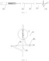
- Fig. 4 is a schematic diagram showing that the annular mapping catheter 10 is used with a cryoballoon catheter 20 according to an embodiment of the present invention.
- the catheter body of the cryoballoon catheter 20 is used to guide the annular mapping catheter 10.
- the distal assembly 13 extends to a balloon 21 through the catheter body of the cryoballoon catheter 20, and contracts within the balloon 21.
- the annular portion 34 is restored to an annular structure due to the shape memory function.
- a pulmonary vein ostium can be initially mapped to diagnose whether the tissue here is a focal point, and part A in Fig. 4 is still within the balloon at this time.
- the cryoballoon catheter 20 performs cryoablation on the tissue.
- the cryoballoon catheter 20 can be withdrawn into the left atrium, the distal assembly 13 can be continuously pushed from the hole 22 at the distal end of the balloon 21, and part A in Fig. 4 extends out of the balloon.
- the bend of the distal assembly 13 is turned from the initial annular structure into the predetermined bend, that is, the predetermined bend including the annular portion 34 and the vertical portion 35.
- the distal assembly 13 is withdrawn, so that the annular portion 34 abuts the position of the effective ablation ring of the balloon 21, that is, the position with the lowest temperature on the cryoballoon.
- the cryoballoon catheter 20 is pushed forward so that the annular portion 34 is pressed against the pulmonary vein ostium, and the tissue here can be mapped by the electrodes on the annular portion 34 to judge whether the ablation is successful.
- the electrodes 33 on the vertical portion 35 may cooperate with the electrodes on the annular portion 34 to locate the positions of the balloon 21. Specifically, after the bend of the distal assembly 13 is turned from the initial annular structure to the predetermined bend, the at least two electrodes on the vertical portion 35 form a straight line, and the straight line may be in line with or substantially in line with the axis of the catheter 10.
- the electrodes on the annular portion 34 form a plane.
- the straight line formed by the at least two electrodes on the vertical portion 35 is perpendicular or substantially perpendicular to the plane formed by the electrodes on the annular portion 34, and the straight line passes through the circle center of the annular portion 34 or substantially passes through the circle center of the annular portion 34.
- the distances between the two electrodes on the vertical portion 35 and the electrodes on the annular portion 34 are constant. Therefore, the height, length, angle and the like of the geometry formed by the connecting lines between the two electrodes on the vertical portion 35 and the electrodes on the annular portion 34 are constant, and the shape and position of the geometry can be determined in a three-dimensional system during operation. Since the annular portion 34 is at the position of the effective ablation ring of the balloon 21, the balloon can be positioned in the three-dimensional system.
- the straight line where the vertical portion 35 is located is perpendicular or substantially perpendicular to the plane formed by the annular portion 34, and the straight line passes through the circle center of the annular portion 34 or substantially passes through the circle center of the annular portion 34.
- the distal assembly 13 can be pushed to extend to the distal end of the balloon through the body of the cryoballoon catheter 20, and the annular portion 34 extends from the hole at the distal end of the balloon.
- the distal assembly When the distal assembly is continuously pushed, the distal assembly 13 extends out of the hole at the distal end of the balloon and is turned into the predetermined bend.
- the annular portion 34 abuts the position of the effective ablation ring of the balloon.
- the cryoballoon catheter can be pushed forward so that the annular portion 34 is pressed against the pulmonary vein ostium, and the tissue here can be mapped by the electrodes on the annular portion 34 to judge whether the ablation is successful.
- Fig. 5 is a modified embodiment of the embodiment shown in Fig. 4 . Except that a development marker 36 is added, other aspects are basically the same as those in Fig. 4 .
- a development marker 36 is disposed at the farthest or substantially farthest position of the predetermined bend, and the development marker 36 may be a development ring or other suitable structure.
- the set of the development marker 36 causes that, during the distal end of the annular mapping catheter 10 is fed into the pulmonary vein ostium, to the development marker 36 may display the position of the distal end of the catheter in real time and display whether the distal end of the catheter reaches the pulmonary vein ostium. According to the position of the development marker 36, it can also be judged whether the bend of the distal assembly 13 is turned from the initial annular structure into the predetermined bend.
Landscapes
- Health & Medical Sciences (AREA)
- Life Sciences & Earth Sciences (AREA)
- Surgery (AREA)
- Veterinary Medicine (AREA)
- Animal Behavior & Ethology (AREA)
- Public Health (AREA)
- Engineering & Computer Science (AREA)
- Biomedical Technology (AREA)
- Heart & Thoracic Surgery (AREA)
- Medical Informatics (AREA)
- Molecular Biology (AREA)
- General Health & Medical Sciences (AREA)
- Biophysics (AREA)
- Physics & Mathematics (AREA)
- Pathology (AREA)
- Nuclear Medicine, Radiotherapy & Molecular Imaging (AREA)
- Otolaryngology (AREA)
- Cardiology (AREA)
- Vascular Medicine (AREA)
- Surgical Instruments (AREA)
- Measurement And Recording Of Electrical Phenomena And Electrical Characteristics Of The Living Body (AREA)
Applications Claiming Priority (2)
| Application Number | Priority Date | Filing Date | Title |
|---|---|---|---|
| CN201810058930.0A CN110063784A (zh) | 2018-01-22 | 2018-01-22 | 一种环形标测导管 |
| PCT/CN2019/072634 WO2019141284A1 (zh) | 2018-01-22 | 2019-01-22 | 一种环形标测导管 |
Publications (3)
| Publication Number | Publication Date |
|---|---|
| EP3744275A1 EP3744275A1 (en) | 2020-12-02 |
| EP3744275A4 EP3744275A4 (en) | 2021-10-27 |
| EP3744275B1 true EP3744275B1 (en) | 2024-03-13 |
Family
ID=67301938
Family Applications (1)
| Application Number | Title | Priority Date | Filing Date |
|---|---|---|---|
| EP19740717.4A Active EP3744275B1 (en) | 2018-01-22 | 2019-01-22 | Annular mapping catheter |
Country Status (5)
| Country | Link |
|---|---|
| US (1) | US11872057B2 (https=) |
| EP (1) | EP3744275B1 (https=) |
| JP (1) | JP7254096B2 (https=) |
| CN (2) | CN110063784A (https=) |
| WO (1) | WO2019141284A1 (https=) |
Families Citing this family (5)
| Publication number | Priority date | Publication date | Assignee | Title |
|---|---|---|---|---|
| US12226141B2 (en) * | 2019-06-27 | 2025-02-18 | Verily Life Sciences Llc | Thin film mapping catheter |
| EP3815641A1 (en) * | 2019-11-04 | 2021-05-05 | Koninklijke Philips N.V. | Electroyphysiological guidance and visualization for balloon, and methods therapy and associated devices, systems |
| CN115969508A (zh) * | 2023-02-01 | 2023-04-18 | 梅达沃科技(上海)有限公司 | 一种环状标测和消融导管及系统 |
| CN116439716B (zh) * | 2023-03-27 | 2024-04-09 | 上海玮启医疗器械有限公司 | 一种标测件和标测导管 |
| CN117481789B (zh) * | 2024-01-03 | 2024-04-02 | 梅奥心磁(杭州)医疗科技有限公司 | 一种双能量多功能电生理导管 |
Family Cites Families (20)
| Publication number | Priority date | Publication date | Assignee | Title |
|---|---|---|---|---|
| US20050234437A1 (en) * | 1999-07-14 | 2005-10-20 | Cardiofocus, Inc. | Deflectable sheath catheters with out-of-plane bent tip |
| US20030120270A1 (en) * | 2001-04-23 | 2003-06-26 | Transurgical, Inc. | Ablation therapy |
| US6764486B2 (en) * | 2002-04-24 | 2004-07-20 | Biotronik Mess- und Therapieger{haeck over (a)}te GmbH & Co. Ingenieurbüro Berlin | Ablation device for cardiac tissue, especially for forming a circular lesion around a vessel orifice in the heart |
| KR101193709B1 (ko) * | 2004-04-19 | 2012-10-23 | 프로리듬, 인크. | 센서 구조체를 구비하는 절제 장치 |
| US7412273B2 (en) * | 2004-11-15 | 2008-08-12 | Biosense Webster, Inc. | Soft linear mapping catheter with stabilizing tip |
| US20080058765A1 (en) * | 2006-08-31 | 2008-03-06 | Pierri Jais | Catheter for linear and circular mapping |
| EP2022397A1 (en) * | 2007-08-08 | 2009-02-11 | ProRhythm, Inc. | Miniature circular mapping catheter |
| WO2010039443A1 (en) * | 2008-10-04 | 2010-04-08 | Boston Scientific Scimed, Inc. | Loop structures for supporting diagnostic and/or therapeutic elements in contact with tissue |
| US8475450B2 (en) * | 2008-12-30 | 2013-07-02 | Biosense Webster, Inc. | Dual-purpose lasso catheter with irrigation |
| CN202020439U (zh) * | 2010-12-16 | 2011-11-02 | 心诺普医疗技术(北京)有限公司 | 灌注式环形标测导管 |
| US9439722B2 (en) * | 2012-05-09 | 2016-09-13 | Biosense Webster (Israel) Ltd. | Ablation targeting nerves in or near the inferior vena cava and/or abdominal aorta for treatment of hypertension |
| EP3019104B1 (en) * | 2013-04-30 | 2025-06-11 | Lake Region Manufacturing, Inc. d/b/a Lake Region Medical | Reverse loop ablation device |
| US9622806B2 (en) * | 2013-07-15 | 2017-04-18 | Medtronic Cryocath Lp | Heated electrodes for continued visualization of pulmonary vein potentials |
| KR101464085B1 (ko) * | 2013-09-03 | 2014-11-21 | 연세대학교 산학협력단 | 혈관 조영이 가능한 다전극 맵핑 폐정맥형 원형 카테터 |
| ES2762122T3 (es) * | 2013-10-24 | 2020-05-22 | Medtronic Ardian Luxembourg | Aparatos de catéter para la modulación de nervios en comunicación con el sistema pulmonar y sistemas asociados |
| US9855089B2 (en) * | 2014-03-21 | 2018-01-02 | Medtronic Cryocath Lp | Shape changing ablation balloon |
| EP3120792A1 (en) | 2015-07-22 | 2017-01-25 | Fiorenzo Gaita | Catheter for cryogenic ablation |
| CN108348146A (zh) * | 2015-11-16 | 2018-07-31 | 阿帕玛医疗公司 | 能量传递装置 |
| CN107583171A (zh) * | 2016-07-08 | 2018-01-16 | 四川锦江电子科技有限公司 | 标测导管及具有其的标测导管组件 |
| CN206045156U (zh) * | 2016-07-08 | 2017-03-29 | 四川锦江电子科技有限公司 | 标测导管及具有其的标测导管组件 |
-
2018
- 2018-01-22 CN CN201810058930.0A patent/CN110063784A/zh active Pending
-
2019
- 2019-01-22 EP EP19740717.4A patent/EP3744275B1/en active Active
- 2019-01-22 US US16/963,804 patent/US11872057B2/en active Active
- 2019-01-22 CN CN201980009334.6A patent/CN111629678B/zh active Active
- 2019-01-22 JP JP2020560536A patent/JP7254096B2/ja active Active
- 2019-01-22 WO PCT/CN2019/072634 patent/WO2019141284A1/zh not_active Ceased
Also Published As
| Publication number | Publication date |
|---|---|
| EP3744275A1 (en) | 2020-12-02 |
| JP7254096B2 (ja) | 2023-04-07 |
| CN110063784A (zh) | 2019-07-30 |
| CN111629678B (zh) | 2024-03-15 |
| US20200359967A1 (en) | 2020-11-19 |
| US11872057B2 (en) | 2024-01-16 |
| CN111629678A (zh) | 2020-09-04 |
| WO2019141284A1 (zh) | 2019-07-25 |
| EP3744275A4 (en) | 2021-10-27 |
| JP2021511170A (ja) | 2021-05-06 |
Similar Documents
| Publication | Publication Date | Title |
|---|---|---|
| AU2018204229B2 (en) | Lasso catheter with tip electrode | |
| CN111388085B (zh) | 一种心脏脉冲多极消融导管 | |
| EP3744275B1 (en) | Annular mapping catheter | |
| US11051881B2 (en) | Lasso catheter with moveable ablation spine | |
| US7163537B2 (en) | Enhanced ablation and mapping catheter and method for treating atrial fibrillation | |
| EP3178433B1 (en) | Multi-electrode balloon catheter with circumferential and point electrodes | |
| EP3111839B1 (en) | Catheter with arcuate end section | |
| EP2229904B9 (en) | Dual-purpose lasso catheter with irrigation | |
| US20050010095A1 (en) | Multi-purpose catheter apparatus and method of use | |
| US20100191232A1 (en) | Catheters and methods for performing electrophysiological interventions | |
| US20170156784A1 (en) | Multilayer split ablation electrode |
Legal Events
| Date | Code | Title | Description |
|---|---|---|---|
| STAA | Information on the status of an ep patent application or granted ep patent |
Free format text: STATUS: THE INTERNATIONAL PUBLICATION HAS BEEN MADE |
|
| PUAI | Public reference made under article 153(3) epc to a published international application that has entered the european phase |
Free format text: ORIGINAL CODE: 0009012 |
|
| STAA | Information on the status of an ep patent application or granted ep patent |
Free format text: STATUS: REQUEST FOR EXAMINATION WAS MADE |
|
| 17P | Request for examination filed |
Effective date: 20200812 |
|
| AK | Designated contracting states |
Kind code of ref document: A1 Designated state(s): AL AT BE BG CH CY CZ DE DK EE ES FI FR GB GR HR HU IE IS IT LI LT LU LV MC MK MT NL NO PL PT RO RS SE SI SK SM TR |
|
| AX | Request for extension of the european patent |
Extension state: BA ME |
|
| DAV | Request for validation of the european patent (deleted) | ||
| DAX | Request for extension of the european patent (deleted) | ||
| REG | Reference to a national code |
Ref country code: DE Ref legal event code: R079 Free format text: PREVIOUS MAIN CLASS: A61B0018020000 Ipc: A61B0005283000 Ref document number: 602019048218 Country of ref document: DE |
|
| A4 | Supplementary search report drawn up and despatched |
Effective date: 20210927 |
|
| RIC1 | Information provided on ipc code assigned before grant |
Ipc: A61B 5/00 20060101ALI20210921BHEP Ipc: A61B 5/318 20210101ALI20210921BHEP Ipc: A61B 18/02 20060101ALI20210921BHEP Ipc: A61B 5/283 20210101AFI20210921BHEP |
|
| STAA | Information on the status of an ep patent application or granted ep patent |
Free format text: STATUS: EXAMINATION IS IN PROGRESS |
|
| 17Q | First examination report despatched |
Effective date: 20220907 |
|
| P01 | Opt-out of the competence of the unified patent court (upc) registered |
Effective date: 20230507 |
|
| RIC1 | Information provided on ipc code assigned before grant |
Ipc: A61B 18/00 20060101ALN20231106BHEP Ipc: A61B 17/00 20060101ALN20231106BHEP Ipc: A61B 18/02 20060101ALI20231106BHEP Ipc: A61B 5/00 20060101ALI20231106BHEP Ipc: A61B 5/318 20210101ALI20231106BHEP Ipc: A61B 5/283 20210101AFI20231106BHEP |
|
| GRAP | Despatch of communication of intention to grant a patent |
Free format text: ORIGINAL CODE: EPIDOSNIGR1 |
|
| STAA | Information on the status of an ep patent application or granted ep patent |
Free format text: STATUS: GRANT OF PATENT IS INTENDED |
|
| INTG | Intention to grant announced |
Effective date: 20231220 |
|
| GRAS | Grant fee paid |
Free format text: ORIGINAL CODE: EPIDOSNIGR3 |
|
| GRAA | (expected) grant |
Free format text: ORIGINAL CODE: 0009210 |
|
| STAA | Information on the status of an ep patent application or granted ep patent |
Free format text: STATUS: THE PATENT HAS BEEN GRANTED |
|
| RAP3 | Party data changed (applicant data changed or rights of an application transferred) |
Owner name: SYNAPTIC MEDICAL (BEIJING) CO. LTD. |
|
| AK | Designated contracting states |
Kind code of ref document: B1 Designated state(s): AL AT BE BG CH CY CZ DE DK EE ES FI FR GB GR HR HU IE IS IT LI LT LU LV MC MK MT NL NO PL PT RO RS SE SI SK SM TR |
|
| REG | Reference to a national code |
Ref country code: GB Ref legal event code: FG4D |
|
| REG | Reference to a national code |
Ref country code: CH Ref legal event code: EP |
|
| REG | Reference to a national code |
Ref country code: DE Ref legal event code: R096 Ref document number: 602019048218 Country of ref document: DE |
|
| REG | Reference to a national code |
Ref country code: IE Ref legal event code: FG4D |
|
| PG25 | Lapsed in a contracting state [announced via postgrant information from national office to epo] |
Ref country code: LT Free format text: LAPSE BECAUSE OF FAILURE TO SUBMIT A TRANSLATION OF THE DESCRIPTION OR TO PAY THE FEE WITHIN THE PRESCRIBED TIME-LIMIT Effective date: 20240313 |
|
| REG | Reference to a national code |
Ref country code: LT Ref legal event code: MG9D |
|
| PG25 | Lapsed in a contracting state [announced via postgrant information from national office to epo] |
Ref country code: GR Free format text: LAPSE BECAUSE OF FAILURE TO SUBMIT A TRANSLATION OF THE DESCRIPTION OR TO PAY THE FEE WITHIN THE PRESCRIBED TIME-LIMIT Effective date: 20240614 |
|
| REG | Reference to a national code |
Ref country code: NL Ref legal event code: MP Effective date: 20240313 |
|
| PG25 | Lapsed in a contracting state [announced via postgrant information from national office to epo] |
Ref country code: RS Free format text: LAPSE BECAUSE OF FAILURE TO SUBMIT A TRANSLATION OF THE DESCRIPTION OR TO PAY THE FEE WITHIN THE PRESCRIBED TIME-LIMIT Effective date: 20240613 Ref country code: HR Free format text: LAPSE BECAUSE OF FAILURE TO SUBMIT A TRANSLATION OF THE DESCRIPTION OR TO PAY THE FEE WITHIN THE PRESCRIBED TIME-LIMIT Effective date: 20240313 |
|
| PG25 | Lapsed in a contracting state [announced via postgrant information from national office to epo] |
Ref country code: ES Free format text: LAPSE BECAUSE OF FAILURE TO SUBMIT A TRANSLATION OF THE DESCRIPTION OR TO PAY THE FEE WITHIN THE PRESCRIBED TIME-LIMIT Effective date: 20240313 |
|
| PG25 | Lapsed in a contracting state [announced via postgrant information from national office to epo] |
Ref country code: RS Free format text: LAPSE BECAUSE OF FAILURE TO SUBMIT A TRANSLATION OF THE DESCRIPTION OR TO PAY THE FEE WITHIN THE PRESCRIBED TIME-LIMIT Effective date: 20240613 Ref country code: NO Free format text: LAPSE BECAUSE OF FAILURE TO SUBMIT A TRANSLATION OF THE DESCRIPTION OR TO PAY THE FEE WITHIN THE PRESCRIBED TIME-LIMIT Effective date: 20240613 Ref country code: LT Free format text: LAPSE BECAUSE OF FAILURE TO SUBMIT A TRANSLATION OF THE DESCRIPTION OR TO PAY THE FEE WITHIN THE PRESCRIBED TIME-LIMIT Effective date: 20240313 Ref country code: HR Free format text: LAPSE BECAUSE OF FAILURE TO SUBMIT A TRANSLATION OF THE DESCRIPTION OR TO PAY THE FEE WITHIN THE PRESCRIBED TIME-LIMIT Effective date: 20240313 Ref country code: GR Free format text: LAPSE BECAUSE OF FAILURE TO SUBMIT A TRANSLATION OF THE DESCRIPTION OR TO PAY THE FEE WITHIN THE PRESCRIBED TIME-LIMIT Effective date: 20240614 Ref country code: FI Free format text: LAPSE BECAUSE OF FAILURE TO SUBMIT A TRANSLATION OF THE DESCRIPTION OR TO PAY THE FEE WITHIN THE PRESCRIBED TIME-LIMIT Effective date: 20240313 Ref country code: ES Free format text: LAPSE BECAUSE OF FAILURE TO SUBMIT A TRANSLATION OF THE DESCRIPTION OR TO PAY THE FEE WITHIN THE PRESCRIBED TIME-LIMIT Effective date: 20240313 Ref country code: BG Free format text: LAPSE BECAUSE OF FAILURE TO SUBMIT A TRANSLATION OF THE DESCRIPTION OR TO PAY THE FEE WITHIN THE PRESCRIBED TIME-LIMIT Effective date: 20240313 |
|
| REG | Reference to a national code |
Ref country code: AT Ref legal event code: MK05 Ref document number: 1664961 Country of ref document: AT Kind code of ref document: T Effective date: 20240313 |
|
| PG25 | Lapsed in a contracting state [announced via postgrant information from national office to epo] |
Ref country code: SE Free format text: LAPSE BECAUSE OF FAILURE TO SUBMIT A TRANSLATION OF THE DESCRIPTION OR TO PAY THE FEE WITHIN THE PRESCRIBED TIME-LIMIT Effective date: 20240313 Ref country code: LV Free format text: LAPSE BECAUSE OF FAILURE TO SUBMIT A TRANSLATION OF THE DESCRIPTION OR TO PAY THE FEE WITHIN THE PRESCRIBED TIME-LIMIT Effective date: 20240313 |
|
| PG25 | Lapsed in a contracting state [announced via postgrant information from national office to epo] |
Ref country code: NL Free format text: LAPSE BECAUSE OF FAILURE TO SUBMIT A TRANSLATION OF THE DESCRIPTION OR TO PAY THE FEE WITHIN THE PRESCRIBED TIME-LIMIT Effective date: 20240313 |
|
| PG25 | Lapsed in a contracting state [announced via postgrant information from national office to epo] |
Ref country code: NL Free format text: LAPSE BECAUSE OF FAILURE TO SUBMIT A TRANSLATION OF THE DESCRIPTION OR TO PAY THE FEE WITHIN THE PRESCRIBED TIME-LIMIT Effective date: 20240313 |
|
| PG25 | Lapsed in a contracting state [announced via postgrant information from national office to epo] |
Ref country code: IS Free format text: LAPSE BECAUSE OF FAILURE TO SUBMIT A TRANSLATION OF THE DESCRIPTION OR TO PAY THE FEE WITHIN THE PRESCRIBED TIME-LIMIT Effective date: 20240713 |
|
| PG25 | Lapsed in a contracting state [announced via postgrant information from national office to epo] |
Ref country code: SM Free format text: LAPSE BECAUSE OF FAILURE TO SUBMIT A TRANSLATION OF THE DESCRIPTION OR TO PAY THE FEE WITHIN THE PRESCRIBED TIME-LIMIT Effective date: 20240313 Ref country code: PT Free format text: LAPSE BECAUSE OF FAILURE TO SUBMIT A TRANSLATION OF THE DESCRIPTION OR TO PAY THE FEE WITHIN THE PRESCRIBED TIME-LIMIT Effective date: 20240715 |
|
| PG25 | Lapsed in a contracting state [announced via postgrant information from national office to epo] |
Ref country code: CZ Free format text: LAPSE BECAUSE OF FAILURE TO SUBMIT A TRANSLATION OF THE DESCRIPTION OR TO PAY THE FEE WITHIN THE PRESCRIBED TIME-LIMIT Effective date: 20240313 Ref country code: EE Free format text: LAPSE BECAUSE OF FAILURE TO SUBMIT A TRANSLATION OF THE DESCRIPTION OR TO PAY THE FEE WITHIN THE PRESCRIBED TIME-LIMIT Effective date: 20240313 |
|
| PG25 | Lapsed in a contracting state [announced via postgrant information from national office to epo] |
Ref country code: AT Free format text: LAPSE BECAUSE OF FAILURE TO SUBMIT A TRANSLATION OF THE DESCRIPTION OR TO PAY THE FEE WITHIN THE PRESCRIBED TIME-LIMIT Effective date: 20240313 |
|
| PG25 | Lapsed in a contracting state [announced via postgrant information from national office to epo] |
Ref country code: PL Free format text: LAPSE BECAUSE OF FAILURE TO SUBMIT A TRANSLATION OF THE DESCRIPTION OR TO PAY THE FEE WITHIN THE PRESCRIBED TIME-LIMIT Effective date: 20240313 |
|
| PG25 | Lapsed in a contracting state [announced via postgrant information from national office to epo] |
Ref country code: SK Free format text: LAPSE BECAUSE OF FAILURE TO SUBMIT A TRANSLATION OF THE DESCRIPTION OR TO PAY THE FEE WITHIN THE PRESCRIBED TIME-LIMIT Effective date: 20240313 |
|
| PG25 | Lapsed in a contracting state [announced via postgrant information from national office to epo] |
Ref country code: SM Free format text: LAPSE BECAUSE OF FAILURE TO SUBMIT A TRANSLATION OF THE DESCRIPTION OR TO PAY THE FEE WITHIN THE PRESCRIBED TIME-LIMIT Effective date: 20240313 Ref country code: SK Free format text: LAPSE BECAUSE OF FAILURE TO SUBMIT A TRANSLATION OF THE DESCRIPTION OR TO PAY THE FEE WITHIN THE PRESCRIBED TIME-LIMIT Effective date: 20240313 Ref country code: RO Free format text: LAPSE BECAUSE OF FAILURE TO SUBMIT A TRANSLATION OF THE DESCRIPTION OR TO PAY THE FEE WITHIN THE PRESCRIBED TIME-LIMIT Effective date: 20240313 Ref country code: PT Free format text: LAPSE BECAUSE OF FAILURE TO SUBMIT A TRANSLATION OF THE DESCRIPTION OR TO PAY THE FEE WITHIN THE PRESCRIBED TIME-LIMIT Effective date: 20240715 Ref country code: PL Free format text: LAPSE BECAUSE OF FAILURE TO SUBMIT A TRANSLATION OF THE DESCRIPTION OR TO PAY THE FEE WITHIN THE PRESCRIBED TIME-LIMIT Effective date: 20240313 Ref country code: IS Free format text: LAPSE BECAUSE OF FAILURE TO SUBMIT A TRANSLATION OF THE DESCRIPTION OR TO PAY THE FEE WITHIN THE PRESCRIBED TIME-LIMIT Effective date: 20240713 Ref country code: EE Free format text: LAPSE BECAUSE OF FAILURE TO SUBMIT A TRANSLATION OF THE DESCRIPTION OR TO PAY THE FEE WITHIN THE PRESCRIBED TIME-LIMIT Effective date: 20240313 Ref country code: CZ Free format text: LAPSE BECAUSE OF FAILURE TO SUBMIT A TRANSLATION OF THE DESCRIPTION OR TO PAY THE FEE WITHIN THE PRESCRIBED TIME-LIMIT Effective date: 20240313 Ref country code: AT Free format text: LAPSE BECAUSE OF FAILURE TO SUBMIT A TRANSLATION OF THE DESCRIPTION OR TO PAY THE FEE WITHIN THE PRESCRIBED TIME-LIMIT Effective date: 20240313 |
|
| REG | Reference to a national code |
Ref country code: DE Ref legal event code: R097 Ref document number: 602019048218 Country of ref document: DE |
|
| PG25 | Lapsed in a contracting state [announced via postgrant information from national office to epo] |
Ref country code: DK Free format text: LAPSE BECAUSE OF FAILURE TO SUBMIT A TRANSLATION OF THE DESCRIPTION OR TO PAY THE FEE WITHIN THE PRESCRIBED TIME-LIMIT Effective date: 20240313 |
|
| PLBE | No opposition filed within time limit |
Free format text: ORIGINAL CODE: 0009261 |
|
| STAA | Information on the status of an ep patent application or granted ep patent |
Free format text: STATUS: NO OPPOSITION FILED WITHIN TIME LIMIT |
|
| PG25 | Lapsed in a contracting state [announced via postgrant information from national office to epo] |
Ref country code: DK Free format text: LAPSE BECAUSE OF FAILURE TO SUBMIT A TRANSLATION OF THE DESCRIPTION OR TO PAY THE FEE WITHIN THE PRESCRIBED TIME-LIMIT Effective date: 20240313 |
|
| 26N | No opposition filed |
Effective date: 20241216 |
|
| PG25 | Lapsed in a contracting state [announced via postgrant information from national office to epo] |
Ref country code: SI Free format text: LAPSE BECAUSE OF FAILURE TO SUBMIT A TRANSLATION OF THE DESCRIPTION OR TO PAY THE FEE WITHIN THE PRESCRIBED TIME-LIMIT Effective date: 20240313 |
|
| REG | Reference to a national code |
Ref country code: DE Ref legal event code: R119 Ref document number: 602019048218 Country of ref document: DE |
|
| REG | Reference to a national code |
Ref country code: CH Ref legal event code: PL |
|
| PG25 | Lapsed in a contracting state [announced via postgrant information from national office to epo] |
Ref country code: MC Free format text: LAPSE BECAUSE OF FAILURE TO SUBMIT A TRANSLATION OF THE DESCRIPTION OR TO PAY THE FEE WITHIN THE PRESCRIBED TIME-LIMIT Effective date: 20240313 Ref country code: LU Free format text: LAPSE BECAUSE OF NON-PAYMENT OF DUE FEES Effective date: 20250122 |
|
| GBPC | Gb: european patent ceased through non-payment of renewal fee |
Effective date: 20250122 |
|
| PG25 | Lapsed in a contracting state [announced via postgrant information from national office to epo] |
Ref country code: DE Free format text: LAPSE BECAUSE OF NON-PAYMENT OF DUE FEES Effective date: 20250801 |
|
| PG25 | Lapsed in a contracting state [announced via postgrant information from national office to epo] |
Ref country code: GB Free format text: LAPSE BECAUSE OF NON-PAYMENT OF DUE FEES Effective date: 20250122 Ref country code: BE Free format text: LAPSE BECAUSE OF NON-PAYMENT OF DUE FEES Effective date: 20250131 |
|
| PG25 | Lapsed in a contracting state [announced via postgrant information from national office to epo] |
Ref country code: FR Free format text: LAPSE BECAUSE OF NON-PAYMENT OF DUE FEES Effective date: 20250131 |
|
| PG25 | Lapsed in a contracting state [announced via postgrant information from national office to epo] |
Ref country code: CH Free format text: LAPSE BECAUSE OF NON-PAYMENT OF DUE FEES Effective date: 20250131 |
|
| REG | Reference to a national code |
Ref country code: BE Ref legal event code: MM Effective date: 20250131 |
|
| PG25 | Lapsed in a contracting state [announced via postgrant information from national office to epo] |
Ref country code: IT Free format text: LAPSE BECAUSE OF NON-PAYMENT OF DUE FEES Effective date: 20250122 |
|
| PG25 | Lapsed in a contracting state [announced via postgrant information from national office to epo] |
Ref country code: IE Free format text: LAPSE BECAUSE OF NON-PAYMENT OF DUE FEES Effective date: 20250122 |