EP3744074B1 - Implementierung eines cloud-netzwerks für eine steuerungsebene eines verteilten antennensystems - Google Patents
Implementierung eines cloud-netzwerks für eine steuerungsebene eines verteilten antennensystems Download PDFInfo
- Publication number
- EP3744074B1 EP3744074B1 EP19744213.0A EP19744213A EP3744074B1 EP 3744074 B1 EP3744074 B1 EP 3744074B1 EP 19744213 A EP19744213 A EP 19744213A EP 3744074 B1 EP3744074 B1 EP 3744074B1
- Authority
- EP
- European Patent Office
- Prior art keywords
- das
- user plane
- plane
- radio frequency
- control plane
- Prior art date
- Legal status (The legal status is an assumption and is not a legal conclusion. Google has not performed a legal analysis and makes no representation as to the accuracy of the status listed.)
- Active
Links
Images


Classifications
-
- H—ELECTRICITY
- H04—ELECTRIC COMMUNICATION TECHNIQUE
- H04L—TRANSMISSION OF DIGITAL INFORMATION, e.g. TELEGRAPHIC COMMUNICATION
- H04L41/00—Arrangements for maintenance, administration or management of data switching networks, e.g. of packet switching networks
- H04L41/08—Configuration management of networks or network elements
- H04L41/0895—Configuration of virtualised networks or elements, e.g. virtualised network function or OpenFlow elements
-
- H—ELECTRICITY
- H04—ELECTRIC COMMUNICATION TECHNIQUE
- H04B—TRANSMISSION
- H04B7/00—Radio transmission systems, i.e. using radiation field
- H04B7/02—Diversity systems; Multi-antenna system, i.e. transmission or reception using multiple antennas
- H04B7/04—Diversity systems; Multi-antenna system, i.e. transmission or reception using multiple antennas using two or more spaced independent antennas
- H04B7/06—Diversity systems; Multi-antenna system, i.e. transmission or reception using multiple antennas using two or more spaced independent antennas at the transmitting station
- H04B7/0602—Diversity systems; Multi-antenna system, i.e. transmission or reception using multiple antennas using two or more spaced independent antennas at the transmitting station using antenna switching
- H04B7/0608—Antenna selection according to transmission parameters
-
- G—PHYSICS
- G06—COMPUTING OR CALCULATING; COUNTING
- G06F—ELECTRIC DIGITAL DATA PROCESSING
- G06F9/00—Arrangements for program control, e.g. control units
- G06F9/06—Arrangements for program control, e.g. control units using stored programs, i.e. using an internal store of processing equipment to receive or retain programs
- G06F9/44—Arrangements for executing specific programs
- G06F9/455—Emulation; Interpretation; Software simulation, e.g. virtualisation or emulation of application or operating system execution engines
- G06F9/45533—Hypervisors; Virtual machine monitors
- G06F9/45558—Hypervisor-specific management and integration aspects
-
- H—ELECTRICITY
- H04—ELECTRIC COMMUNICATION TECHNIQUE
- H04B—TRANSMISSION
- H04B7/00—Radio transmission systems, i.e. using radiation field
- H04B7/02—Diversity systems; Multi-antenna system, i.e. transmission or reception using multiple antennas
- H04B7/022—Site diversity; Macro-diversity
- H04B7/024—Co-operative use of antennas of several sites, e.g. in co-ordinated multipoint or co-operative multiple-input multiple-output [MIMO] systems
-
- H—ELECTRICITY
- H04—ELECTRIC COMMUNICATION TECHNIQUE
- H04L—TRANSMISSION OF DIGITAL INFORMATION, e.g. TELEGRAPHIC COMMUNICATION
- H04L41/00—Arrangements for maintenance, administration or management of data switching networks, e.g. of packet switching networks
- H04L41/06—Management of faults, events, alarms or notifications
- H04L41/069—Management of faults, events, alarms or notifications using logs of notifications; Post-processing of notifications
-
- H—ELECTRICITY
- H04—ELECTRIC COMMUNICATION TECHNIQUE
- H04L—TRANSMISSION OF DIGITAL INFORMATION, e.g. TELEGRAPHIC COMMUNICATION
- H04L41/00—Arrangements for maintenance, administration or management of data switching networks, e.g. of packet switching networks
- H04L41/08—Configuration management of networks or network elements
- H04L41/0803—Configuration setting
- H04L41/0806—Configuration setting for initial configuration or provisioning, e.g. plug-and-play
-
- H—ELECTRICITY
- H04—ELECTRIC COMMUNICATION TECHNIQUE
- H04W—WIRELESS COMMUNICATION NETWORKS
- H04W80/00—Wireless network protocols or protocol adaptations to wireless operation
- H04W80/08—Upper layer protocols
-
- H—ELECTRICITY
- H04—ELECTRIC COMMUNICATION TECHNIQUE
- H04W—WIRELESS COMMUNICATION NETWORKS
- H04W88/00—Devices specially adapted for wireless communication networks, e.g. terminals, base stations or access point devices
- H04W88/08—Access point devices
- H04W88/085—Access point devices with remote components
-
- H—ELECTRICITY
- H04—ELECTRIC COMMUNICATION TECHNIQUE
- H04W—WIRELESS COMMUNICATION NETWORKS
- H04W88/00—Devices specially adapted for wireless communication networks, e.g. terminals, base stations or access point devices
- H04W88/12—Access point controller devices
-
- G—PHYSICS
- G06—COMPUTING OR CALCULATING; COUNTING
- G06F—ELECTRIC DIGITAL DATA PROCESSING
- G06F9/00—Arrangements for program control, e.g. control units
- G06F9/06—Arrangements for program control, e.g. control units using stored programs, i.e. using an internal store of processing equipment to receive or retain programs
- G06F9/44—Arrangements for executing specific programs
- G06F9/455—Emulation; Interpretation; Software simulation, e.g. virtualisation or emulation of application or operating system execution engines
- G06F9/45533—Hypervisors; Virtual machine monitors
- G06F9/45558—Hypervisor-specific management and integration aspects
- G06F2009/45595—Network integration; Enabling network access in virtual machine instances
-
- H—ELECTRICITY
- H04—ELECTRIC COMMUNICATION TECHNIQUE
- H04L—TRANSMISSION OF DIGITAL INFORMATION, e.g. TELEGRAPHIC COMMUNICATION
- H04L41/00—Arrangements for maintenance, administration or management of data switching networks, e.g. of packet switching networks
- H04L41/02—Standardisation; Integration
- H04L41/0246—Exchanging or transporting network management information using the Internet; Embedding network management web servers in network elements; Web-services-based protocols
- H04L41/0253—Exchanging or transporting network management information using the Internet; Embedding network management web servers in network elements; Web-services-based protocols using browsers or web-pages for accessing management information
-
- H—ELECTRICITY
- H04—ELECTRIC COMMUNICATION TECHNIQUE
- H04W—WIRELESS COMMUNICATION NETWORKS
- H04W4/00—Services specially adapted for wireless communication networks; Facilities therefor
- H04W4/90—Services for handling of emergency or hazardous situations, e.g. earthquake and tsunami warning systems [ETWS]
Definitions
- a Distributed Antenna System typically includes at least one master unit that is communicatively coupled with a plurality of remote antenna units. Each remote antenna unit can be coupled directly to the master unit or indirectly via one or more other remote antenna units and/or via one or more intermediary or expansion units.
- a DAS is typically used to improve the coverage provided by one or more base stations that are coupled to the master unit. These base stations can be coupled to the master unit via one or more cables or via a wireless connection, for example, using one or more donor antennas. In some implementations, a DAS may comprise more than one such master unit, for example to address redundancy concerns.
- the wireless service provided by the base stations can included commercial cellular service and/or public safety wireless communications.
- a DAS is typically controlled by various software applications executed by a DAS controller which is implemented within a master unit of the DAS.
- the master unit may comprise rack mounted controller hardware that includes a processor that executes the various functions of the DAS controller.
- the DAS controller may be implemented by electronic components and processors located directly on the backplane of the DAS master unit.
- Functions performed by the DAS controller typically includes applications for managing aspects of controlling the DAS such as, but not limited to, hardware population, cabling, managing software updates, managing and maintaining a database of DAS hardware configuration, uplink and downlink RF component configurations, and overall system configuration, leveling of uplink and downlink RF signals, hardware diagnostics, generating and distributing alarms, and maintaining a log of alarms in a database on the DAS controller.
- the DAS controller typically also includes an SNMP interface providing operations and maintenance (O&M) access to the system operators, and may include a server providing a Web page interface for administration of the DAS.
- O&M operations and maintenance
- the DAS controller implements the logic for controlling the signal processing and forwarding behavior of RF traffic through the DAS between the one or more base stations and user devices which are in wireless communication with the plurality of remote antenna units.
- This logic may be referred to as the DAS "control plane.”
- the DAS "user plane” provides the transport platform that forwards the RF traffic through the DAS according to the directions provided to the DAS user plane by the DAS control plane.
- both the control plane and user plane comprise hardware specific software that utilizes low level software that directly interfaces with the DAS hardware electronics, such a memories, registers, interrupts, and the like.
- This hardware specific software would be supplied by the DAS developer and provided to the operator at the time the DAS hardware is installed.
- a telecommunications system operator that owns and operates multiple DAS installations, not only needs to access each DAS installation separately to make updates, reconfigurations, or respond to alarm messages, but they also need maintain familiarity with the software and user interfaces associated with each installation.
- scalability of the control plane at each DAS installation is limited by processing resources present and available for the DAS controller on the DAS hardware, thus potentially limiting the ability of a DAS operator to implement new protocols and standards and/or address increasing RF traffic demands.
- EP 2719138 A2 published 16 April 2014 , relates to an interface for processing digital signals in a standardized format in a DAS.
- One example includes a unit disposed in a DAS.
- the unit includes an interface section and an output section.
- the interface section is configured for outputting a first complex digital signal and a second complex digital signal.
- the first complex digital signal is generated from a digital signal in a standardized format received from a digital base station.
- the output section is configured for combining the first complex digital signal and the second complex digital signal into a combined digital signal.
- the output section is also configured for outputting the combined digital signal.
- the combined digital signal comprises information to be wirelessly transmitted to a wireless user device.
- US 2015/282069 A1 published 1 October 2015 , relates to power management subsystems for a DAS or other telecommunication system.
- the power management subsystem can include a measurement module and an optimization module.
- the measurement module can monitor a utilization metric for a remote unit in the DAS or other telecommunication system.
- the power optimization module can determine whether the remote unit is underutilized based on the monitored utilization metric.
- the power optimization module can configure the remote unit for a low-power operation in response to determining that the remote unit is underutilized.
- Embodiments of the present disclosure provide for cloud network implementation for a distributed antenna system control plane and will be understood by reading and studying the following specification.
- a DAS architecture comprises: a DAS cloud computing network; a first distributed antenna system comprising at least a first user plane, wherein the first user plane includes uplink circuity and downlink circuity, wherein the uplink circuity forwards uplink radio frequency traffic from at least one remote antenna unit of the first distributed antenna system to at least one master unit of the first distributed antenna system, wherein the downlink circuity forwards downlink radio frequency traffic from the least one master unit to the at least one remote antenna unit; wherein the DAS cloud computing network comprises a control plane in communication with the first user plane of the first distributed antenna system through a network; wherein the first user plane comprises a high level protocol interface abstraction layer coupled to the network and processes and forwards the uplink and downlink radio frequency traffic based on configuration commands received from the control plane via the high level protocol interface abstraction layer.
- Embodiments of the present disclosure address limitations of DAS controllers in the art today through the separation of DAS control and user planes by the introduction of high level hardware access protocol interface and by off-boarding the DAS control plane functionality from the local DAS hardware and implementing the DAS controller either as virtual machine (VM) executed in a cloud network or as DAS applications offered as a cloud service by the cloud network.
- VM virtual machine
- an interface between the control plane and user plane is achieved using high level command and response protocols that are non-hardware specific. That is, the interface between the control and the user plane provides high level description of data and commands to control the user plane and exchange information.
- the user plane processes and forwards uplink and downlink radio frequency traffic based on configuration messages received from a control plane.
- the interface between further provides an abstraction from the underlying hardware so that the DAS controller does not require any detailed knowledge of the hardware to be configured and controlled, thus avoiding the need for the DAS controller to utilize low level hardware command sequences to communicate instructions to the user plane.
- digital as well as analog user plane hardware can be used transparently via the high level protocol interface.
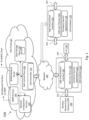
- FIG. 1 is a diagram illustrating a DAS architecture 100 for one embodiment of the present disclosure where the DAS controller and user planes are separated.
- a user plane 110 is implemented in DAS hardware 112 by executing hardware specific user plane applications 114 that process and transport RF communication traffic between one or more wireless network base stations 102 (shown as communication traffic 103) and user equipment 104 (shown as communication traffic 105).
- the user plane applications 114 may be executed by controllers in DAS master units, remote antenna units, extension and/or expansion units, or some combination thereof.
- the control plane 120 is implemented virtually in by a DAS cloud computing network 122 (referred to herein as a "DAS cloud” 122) in order to realize the DAS controller 124. That is, one or more network nodes of the DAS cloud 122 may comprise processors that execute the functions described herein of the control plane 122 and DAS controller 124. Moreover, the storage for persistent system level data (previously maintained on DAS hardware 112) may also be separated into the DAS cloud 122 and maintained on a data plane 130 (for example, a shared database) on DAS cloud 122 that is accessible from the DAS controller 124 via a defined data access protocol.
- a data plane 130 for example, a shared database
- the data plane 130 is also separate from the DAS controller 124 within DAS cloud 112, to allow for moving database tables to dedicated machines (either real or virtual machines) and thus further improve performance and scalability. Additionally, databases can be shared between DAS cloud 112 components such as, but not limited to, Network Configuration Services, O&M services, the DAS Controller and the WWW Backend Server which avoids redundancies in data and further speeds up the data access.
- DAS cloud 112 components such as, but not limited to, Network Configuration Services, O&M services, the DAS Controller and the WWW Backend Server which avoids redundancies in data and further speeds up the data access.
- the user plane 110 implemented in DAS hardware 112, and the DAS controller 124 implemented in DAS cloud 122 are communicatively coupled via a network 140 (which may comprise an Internet Protocol (IP) network such as the Internet, for example).
- IP Internet Protocol
- the user plane 110 includes a high level command and response protocol interface 142 (referred to herein as "high level protocol interface") through which the DAS controller 124 communicates to the user plane 110.
- High level protocol interface 142 provides an abstraction layer through which the DAS controller 124 can send non-hardware specific commands and data in order to configure operation of the user plane 110.
- the high level protocol interface 142 can communicate with the components of DAS hardware 112, either directly or indirectly, to configure the DAS hardware 112 to operate as directed by the DAS controller 124.
- the DAS controller 124 may send a command to the user plane 110 via high level protocol interface 142 to vary the transmit power of a first cellular band, designated RF band #1 for example.
- the DAS controller 124 may simply pass to the high level protocol interface 142 the designated band "RF band #1" and the desired transmit power, without the need for any underlying knowledge about which hardware registers, amplifiers, processors, etc. of DAS hardware 112 handle the processing of RF band #1.
- the high level protocol interface 142 interprets such instructions into DAS hardware 112 specific instructions in order to carry out the high-level commands received form the DAS controller 124.
- hardware level alarms or messages generated by the DAS hardware 112 may be received by the high level protocol interface 142 and translated to a high-level alarm notification to the DAS controller 124 over network 140.
- the DAS cloud 122 may further comprise servers or network nodes.
- the network nodes may comprise processors that implement network configuration services 145, an internet World Wide Web (WWW) backend server 143, a northbound interface (NBI) to operations and maintenance service 144, or both, with which the DAS operator may interact with, and control, any aspect of the control plane 120 and/or data plane 130.
- WWW World Wide Web
- NBI northbound interface
- MVC Model View Controller
- architecture 100 may be expanded in other embodiments to include multiple user plane entities which are managed by a control plane 120 from the DAS cloud 122. That is, one or more additional instances of user plane entities, which may be operated either in conjunction with DAS hardware 112 or completely independent from DAS hardware 112, may be managed and operated using architecture 100.
- one or more additional user planes 152 may be communicatively coupled to the DAS cloud 122 via network 140 and operated in the same manner as described above regarding user plane 110.
- the additional user planes 152 may be executed by DAS hardware 150 which is separate and independent from DAS hardware 112.
- one or more of the additional user planes 152 may also be executed by DAS hardware 112.
- Each of the additional user planes 152 comprises a high level command and response protocol interface 154 and may be communicatively coupled to the DAS cloud 122 via network 140 and operated in the same manner as described above regarding DAS hardware 112 and user plane 110. In this way, multiple DAS installations may be managed by an operator via the DAS cloud 122 without the need to connect to and utilize hardware specific software for each installation. Moreover, in some embodiments, the storage for persistent system level data for DAS hardware 112 and DAS hardware 150 (and/or any other DAS installations) is maintained together on data plane 130, thus providing a database that comprises a shared set of tables for all pertinent information relevant to the operator's communication system.
- the separation of the control and user planes of a DAS as illustrated by DAS architecture 100 supports scalability with respect to increasing RF communications traffic between BTS and user devices by enabling the DAS operator to add user plane nodes without changing the number of controllers in the network.
- Other benefits include a clear control and O&M interface between control plane and user plane, the flexibility to locate and scale the control plane and control plane resources independent of the processing resources available at the DAS, and independent evolution and development of the control plane and user plane functions.
- the control plane implemented in the DAS cloud can be technology agnostic and control analog as well as digital user planes, and used in conjunction with multiple user plane entities.
- certain functions of a DAS control plane are rarely used, or may even just be used once at the time of DAS commissioning. With such functions implemented by software executed in the DAS cloud, a single installation of the software can be shared by multiple user plane entities.
- a DAS controller 124 may be realized either by establishing one or more DAS controller virtual machines in DAS cloud 122, or by directly providing DAS applications associated with DAS controller functions as services available from DAS cloud 122. It should be understood that the virtualized DAS Controllers and Cloud Services, and network nodes, servers, gateways, and/or other components comprising the DAS cloud 122 may be executed from a data center of a DAS operator and/or any other cloud service provider. In fact, the physical location of the control plane/DAS Controller is no longer relevant as only the user plane 110 and RF components comprising the DAS hardware 112 need to be located at the DAS site. DAS cloud 122 resources can be allocated on demand and expenses incurred from running the DAS Controller, System Configuration, and Network Element Management Functions, for example, can be tailored to the needs of the system operator.
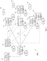
- FIG. 2 is a block diagram illustrating an example DAS 200 (also referred to herein as a DAS installation) of one embodiment of the present disclosure.
- DAS 200 comprises one or more master units 210 that are communicatively coupled to one or more remote antenna units 212 via one or more communication links 214.
- the communication links 214 may comprise wireless communication links, cables (i.e. wired communication links), or some combination thereof.
- the term cable is used generically and may refer to either electrical or fiber optic cables, or hybrid cables comprising both electrical conductors and optical fibers. It should be understood that DAS 200 may provide wireless telecommunication services to a building, plant, campus, transportation hub, tunnel, or any other type of facility.
- the communication links 214 discussed herein may each operate bidirectionally with downlink and uplink communications carried over the link. It should also be understood, however, that in other embodiments, a communication link 214 may itself further comprise a pair of links including, for example, an uplink cable for uplink communication, and a downlink cable for downlink communication.
- Each remote antenna unit 212 can be communicatively coupled directly to one or more of the master units 210 or indirectly via one or more other remote antenna units 212 and/or via one or more intermediary or expansion units 213.
- DAS 200 may further include one or more extension units 215 that are communicatively coupled to a remote antenna unit 212 to further extend coverage.
- control plane 120 is separated from user plane 110 by implementing the control plane 120 as a DAS controller on a separate machine (as shown at 216) and/or in a virtualized environment or in the cloud as discussed in greater detail below. Regardless of where or how the functions of a DAS controller 216 are specifically implemented, control plane 120 functions for the DAS 200 are executed on a platform separate from the DAS 200 hardware and their associated services provided to each of the Master Unit 210, Remote Antenna Units 212, and Expansion Units 213 and Extension Units 215 (when present) via the high level protocol interface 142.
- Each master unit 210 is communicatively coupled to one or more base stations 102 (such as the wireless network base stations 102 described in Figure 1 ).
- one or more of the base stations 102 can be co-located with the respective master units 210 to which it is coupled (for example, where the base station 102 is dedicated to providing base station capacity to the DAS 200 and is coupled to the respective master units 210).
- one or more of the base stations 102 can be located remotely from the respective master units 210 to which it is coupled (for example, where the base station 102 provides base station capacity to an area beyond the coverage area of the DAS 200). In this latter case, the master unit 210 can be coupled to a donor antenna and repeater or bidirectional amplifier in order to wirelessly communicate with the remotely located base station 102.
- the base stations 102 include one or more base stations that are used to provide public and/or private safety wireless services (for example, wireless communications used by emergency services organizations (such as police, fire and emergency medical services) to prevent or respond to incidents that harm or endanger persons or property. Such base stations are also referred to here as “safety wireless service base stations” or “safety base stations.”
- the base stations 102 also can include, in addition to safety base stations, one or more base stations that are used to provide commercial cellular wireless service. Such base stations are also referred to here as "commercial wireless service base stations" or "commercial base stations.”
- the base stations 102 can be coupled to the master units 210 using a network of attenuators, combiners, splitters, amplifiers, filters, cross-connects, etc., (sometimes referred to collectively as a "point-of-interface" or "POI").
- This network can be included in the master units 210 and/or can be separate from the master units 210. This is done so that, in the downlink, the desired set of RF channels output by the base stations 102 can be extracted, combined, and routed to the appropriate master units 210, and so that, in the upstream, the desired set of carriers output by the master units 210 can be extracted, combined, and routed to the appropriate interface of each base station 102. It is to be understood, however, that this is one example and that other embodiments can be implemented in other ways.
- each master unit 210 comprises downlink DAS circuitry 211, uplink DAS circuitry 224 and a controller 230 (that together comprise a segment of the DAS hardware 112) and hardware specific applications 114 that execute on the controller 230 (for example to implement the high level protocol interface 142).
- These elements together define the user plane 110 within the master unit 210 that processes and transports RF communications traffic 103 and 105 between the one or more wireless network base stations 102 and user equipment 104.
- Control plane services for the DAS 200 are separated from the master unit 210 and implemented elsewhere, such as by DAS controller 216 described below.
- High level protocol interface 142 provides the necessary connectivity between master unit 210 and systems implementing the control plane services.
- Downlink DAS circuitry 211 is configured to receive one or more downlink signals from one or more base stations 102. These signals are also referred to here as “base station downlink signals.” Each base station downlink signal includes one or more radio frequency channels used for communicating in the downlink direction with user equipment 104 (such as tablets or cellular telephone, for example) over the relevant wireless air interface. Typically, each base station downlink signal is received as an analog radio frequency signal, though in some embodiments one or more of the base station signals are received in a digital form (for example, in a digital baseband form complying with the Common Public Radio Interface (“CPRI") protocol, Open Radio Equipment Interface (“ORI”) protocol, the Open Base Station Standard Initiative (“OBSAI”) protocol, or other protocol).
- CPRI Common Public Radio Interface
- ORI Open Radio Equipment Interface
- OBSAI Open Base Station Standard Initiative
- each master unit 210 is also configured to generate one or more downlink transport signals derived from one or more base station downlink signals and to transmit one or more downlink transport signals to one or more of the remote antenna units 212.
- Each master unit 210 also comprises the uplink DAS circuitry 224 that is configured to receive the respective uplink transport signals transmitted to it from one or more remote antenna units 212 and to use the received uplink transport signals to generate one or more base station uplink radio frequency signals that are provided to the one or more base stations 102. Typically, this involves, among other things, combining or summing uplink signals received from multiple remote antenna units 212 in order to produce the base station signal provided to each base station 102.
- Each base station uplink signal includes one or more of the uplink radio frequency channels used for communicating with user equipment 104 over the wireless air interface. In this way, the DAS 200 increases the coverage area for the uplink capacity provided by the base stations 102.
- each remote antenna unit 212 in general, comprises downlink DAS circuitry 218, uplink DAS circuitry 221 and a controller 230 (that together comprise a segment of the DAS hardware 112) and hardware specific applications 114 that execute on the controller 230 (for example to implement the high level protocol interface 142).
- Downlink DAS circuitry 218 is configured to receive the downlink transport signals transmitted to it from one or more master units 210 and to use the received downlink transport signals to generate one or more downlink radio frequency signals that are radiated from one or more antennas 219 associated with that remote antenna unit 212 for reception by user equipment 104.
- These downlink radio frequency signals are analog radio frequency signals and are also referred to here as "remote downlink radio frequency signals.”
- Each remote downlink radio frequency signal includes one or more of the downlink radio frequency channels used for communicating with user equipment 104 over the wireless air interface.
- each remote antenna unit 212 comprises uplink DAS circuitry 221 that is configured to receive via antenna(s) 219 one or more uplink radio frequency signals transmitted from the user equipment 104. These signals are analog radio frequency signals and are also referred to here as "remote uplink radio frequency signals.” Each uplink radio frequency signal includes one or more radio frequency channels used for communicating in the uplink direction with user equipment 104 over the relevant wireless air interface.
- the uplink DAS circuitry 221 in each remote antenna unit 212 is also configured to generate one or more uplink transport signals derived from the one or more remote uplink radio frequency signals and to transmit one or more uplink transport signals to one or more of the master units 210.
- each expansion unit 213, in general, comprises downlink DAS circuitry 226, uplink DAS circuitry 228 and a controller 230 (that together comprise a segment of the DAS hardware 112) and hardware specific applications 114 that execute on the controller 230 (for example to implement the high level protocol interface 142).
- Downlink DAS circuitry 226 that is configured to receive the downlink transport signals transmitted to it from the master unit 210 (or other expansion unit 213) and transmits the downlink transport signals to one or more remote antenna units 212 or other downstream intermediary units 213.
- Each expansion unit 213 comprises uplink DAS circuitry 228 that is configured to receive the respective uplink transport signals transmitted to it from one or more remote antenna units 212 or other downstream intermediary units 213, combine or sum the received uplink transport signals, and transmit the combined uplink transport signals upstream to the master unit 210 or other expansion unit 213.
- one or more remote antenna units 212 may be coupled to the one or more master units 210 via one or more other remote antenna units 212 (for examples, where the remote antenna units 212 are coupled together in a daisy chain or ring topology).
- an expansion unit 213 may be implemented using a remote antenna units 212.
- each extension unit 215, in general, comprises downlink DAS circuitry 238, uplink DAS circuitry 231 and a controller 230 (that together comprise a segment of the DAS hardware 112) and hardware specific applications 114 that execute on the controller 230 (for example to implement the high level protocol interface 142).
- Downlink DAS circuitry 238 is configured to receive the downlink transport signals transmitted to it from a remote antenna unit 212 and to use the received downlink transport signals to generate one or more downlink radio frequency signals that are radiated from one or more antennas 219 associated with that extension unit 215 for reception by user equipment 104.
- Each downlink radio frequency signal includes one or more of the downlink radio frequency channels used for communicating with user equipment 104 over the wireless air interface.
- Each extension unit 215 may further comprise uplink DAS circuitry 231 that is configured to receive via antenna(s) 219 one or more uplink radio frequency signals transmitted from the user equipment 104. These signals are analog radio frequency signals and are also referred to here as "uplink radio frequency signals.” Each uplink radio frequency signal includes one or more radio frequency channels used for communicating in the uplink direction with user equipment 104 over the relevant wireless air interface.
- the uplink DAS circuitry 231 in each extension unit 215 may also be configured to generate one or more uplink transport signals derived from the one or more remote uplink radio frequency signals and to transmit one or more uplink transport signals to the remote antenna unit 212 to which it is coupled.
- the uplink DAS circuitry 221 in a remote antenna unit 212 may be further configured to receive the respective uplink transport signals transmitted to it from an extension unit 215 and to use the received uplink transport signals to generate uplink radio frequency signals that are provided to the master unit 210.
- a DAS Controller 216 in general may comprise a controller 232 that executes the DAS Control Plane Services 240 to realize the control plane function for DAS 200 either on a separate machine, in a virtualized environment or in the cloud.
- the high level protocol interface 142 in the DAS Controller 216 provides the necessary connectivity between DAS Controller 216 and the DAS 200 user plane functions that are executed on the various DAS 200 hardware components.
- the DAS Controller 216 may comprise a modem 235 in order to communicatively couple DAS Controller 216 to network 140.
- the downlink DAS circuitry 211, 218, 226, and 238 and uplink DAS circuitry 224, 221, 228 and 231 in each master unit 210, remote antenna unit 212, expansion unit 213, and extension unit 215, respectively, can comprise one or more appropriate connectors, attenuators, combiners, splitters, amplifiers, filters, duplexers, analog-to-digital converters, digital-to-analog converters, mixers, field-programmable gate arrays (FPGAs), microprocessors, transceivers, framers, etc., to implement the features described above.
- the downlink DAS circuitry 211, 218, 226, and 238 and uplink DAS circuitry 224, 221, 228 and 231 may share common circuitry and/or components. For example, some components (such as duplexers) by their nature are shared among the downlink DAS circuitry 211, 218, 226, and 238 and uplink DAS circuitry 224, 221, 228 and 231.
- the DAS 200 can use either digital transport, analog transport, or combinations of digital and analog transport for generating and communicating the transport signals between the base station 102, the master units 210, the remote antenna units 212, and any expansion units 213.
- some of the embodiments described here are implemented using analog transport over optical cables.
- other embodiments can be implemented in other ways, for example, in DASs that use other types of analog transport (for example, using other types of cable and/or using analog transport that makes use of frequency shifting), digital transport (for example, where digital samples indicative of the analog base station radio frequency signals and analog remote radio frequency signals are generated and communicated between the master units 210 and the remote antenna units 212), or combinations of analog and digital transport.
- Each unit 210, 212, 213, 215 in the DAS 200 can also comprise a respective controller 230, which as discussed above, executes the hardware specific user plane applications 114 and high level protocol interface 142 for the user plane 110 implemented within that particular unit.
- the controller 230 is implemented using one or more programmable processors and memory hardware that execute software that is configured to implement the various features described here as being implemented by the controller 230.
- the controller 230, the various features described here as being implemented by the controller 230, or portions thereof, can be implemented in other ways (for example, in a field programmable gate array (FPGA), application specific integrated circuit (ASIC), etc.).
- the master unit 210 may comprise a modem 235 communicatively coupled to network 140.
- each unit 210, 212, 213, 215 in the DAS 200 is also configured to send and receive management and control data with control plane 120 via a high level protocol implemented by the high level protocol interface 142.
- FIG 3 illustrates an example embodiment of a DAS architecture 300 providing an example implementation of the DAS architecture 100 discussed with respect to Figure 1 .
- DAS architecture 300 one or more DAS Controllers are implemented as DAS Controller Virtual Machine(s) 320 within DAS cloud 120.
- the web backend is realized using a Web Backend Virtual Machine (VM) 342 (i.e., a web server) and the data plane 130 is realized using a Data Base Virtual Machine (VM) 333 which comprises the shared database 330.
- VM Web Backend Virtual Machine
- VM Data Base Virtual Machine
- Communication between the DAS Controller Virtual Machine(s) 320, the Web Backend Virtual Machine 342, and the Shared Database 330 may be implemented by a Message and Data Bus 322, through which every functional entity of DAS cloud 122 can access data and send commands to any other entity coupled to bus 322.
- the Message and Data Bus 322 may be implemented, for example, using ethernet or any other type of communications technology.
- DAS architecture 300 may include multiple user plane entities (shown at 310) communicatively coupled to DAS cloud 120 via a communications network 140.
- Each of the user plane entities 310 may comprise a user plane 110 such as shown in Figure 1 and correspond to the user plane of a DAS as shown in Figure 2 .
- communications between the DAS Controller Virtual Machines 320 and the user planes 310 may be based on IP protocols and/or secured by VPN tunnels and/or firewalls.
- DAS cloud 120 further comprises a virtual Ethernet switch 324 that switches Ethernet packets between the user plane entities 310 and the DAS Controller Virtual Machine 320 with which they are associated.
- the DAS architecture 300 may further comprise a System Configuration Virtual Machine 330, and a Network Element Management Virtual Machine 332, each implemented by DAS cloud 120 and coupled to Message and Data Bus 322.
- Integration of the DAS Controller functionality and sharing of DAS system data in DAS cloud 120 with the System Configuration Virtual Machine 330 and Network Element Management Virtual Machine 332 may be achieved by sharing common data stored in the shared database 330 and/or by using the same web backend 342 and a web frontend 344 (i.e., a WWW client) for user access.
- the web frontend client 244 may be executed by a human interface device integrated into a server or other node coupled to DAS cloud 120.
- System Configuration Virtual Machine 330 executes one or more applications which may be used to configure operation of various aspects of the DAS cloud 120.
- the System Configuration Virtual Machine 330 executes applications that manage functions such as, but not limited to: RF Network Planning, RF Output Power Management, Optical Transport Capacity Management, Service Distribution Configuration, Hardware Configuration & bill-of-material (BOM), Inventory, and DAS Cloud user rights management.
- the Network Element Management Virtual Machine 332 provides the interface to the proprietary operations and maintenance services 144 for the network operator to control their DAS installations (for example via a northbound interface (NBI) to operations and maintenance service).
- NBI northbound interface
- the Network Element Management Virtual Machine 332 may execute one or more applications to provide functions such as, but not limited to: Fault Management (which may include generating, distributing and logging active alarms, alarm history, remedy, acknowledgement, etc.), Configuration Management (which may include hardware and RF electronics connectivity and alarm parameter changes, for example), Inventory Management (which may include an inventory of DAS hardware and software components and change history), Performance Management (which may include Alarm Statistics, hardware and RF component data graphs, etc.), User Management (which may include role and rights administration of user accounts for the system operator), Security Management (which may include VPN management, NE Base Image updates, control of software / application inventory), and or application or script processing for automation of routine tasks (such as software distribution and activation, NE backup, managing bulk configuration changes, etc.).
- Fault Management which may include generating, distributing and logging active alarms, alarm history, remedy, acknowledgement, etc.
- Configuration Management which may include hardware and RF electronics connectivity and alarm parameter changes, for example
- Inventory Management which may include an inventory of DAS hardware
- access to the common data stored in the shared database 330 may also be obtained via a WWW webpage server implemented by web backend 342 and accessed by a web frontend client (or web client user interface) 344.
- Web client user interface 344 thus provides a common user interface and single access point for a user to manage the operation and configuration of any user plane entity 310.
- the web backend 242 may serve web pages associated with each of various DAS applications provided by the virtual machines implemented in the DAS cloud 122 (for example, DAS Controller VMs 320, Network Element Management System VM 332, and/or System Configuration VM 330) to the web frontend client 344.
- the web backend VM 342 may interface with each of the respective DAS applications via a defined Application Programing Interface (API) (for example, using a Representational state transfer API, or JavaScript Object Notation based messaging) to request information and trigger commands and forwards the results to the web frontend client 344.
- API Application Programing Interface
- the web backend VM 342 may also have direct access to the shared database 330 rather than depend on access via the virtual machines.
- different roles in DAS Commissioning and Operation as well as access control may be handled via user management from the common user interface provided by the web frontend client 344.
- the virtualization of the control plane 120 functions for execution by the DAS cloud 122 saves costs over the need to provide dedicated DAS controllers locally at each DAS installation, and provides the flexibility that one controller can essentially be used to replace multiple traditional DAS control planes.
- Scalability for a DAS controller 320 in DAS architecture 300 is also obtained through the ability to simply allocate additional processing resources from within the DAS Cloud 122 (for example, additional or more powerful processing units, memory, disk space, etc.) to the virtual machine 320 that executes that respective DAS controller.
- a DAS controller 124 may be realized either by establishing one or more DAS controller virtual machines in DAS cloud 122, or by directly providing DAS applications associated with DAS controller functions as services available from DAS cloud 122.
- FIG. 4 illustrates an alternative embodiment of a DAS architecture 400 for another example implementation of the DAS architecture 100.
- DAS architecture 400 the DAS applications associated with the DAS controllers, System Configuration, and Network Element Management functions discussed above are directly provided as services available from applications executed by the DAS cloud 122. That is, the virtualized applications discussed in DAS architecture 400 are broken up into single functions that are grouped into separate cloud services 410, 412 and 414. Each of the cloud services are in turn implemented by the execution of particular applications by processors on nodes of DAS cloud 122.
- the separate cloud services provided by DAS cloud 122 are grouped into Network Planning and Configuration Services 410 (which may include applications that execute functions such as RF Planning, BOM Creation, Optical Transport Configuration, for example ), DAS Control Plane Services 412 (which may include applications that execute functions use at the time a DAS is commissioned, such as hardware population, cabling, leveling, service configuration, for example) and Operation and Maintenance Services 414 (which may include applications that execute functions such as RF Monitoring, Alarm functions, Performance Management, and so forth) which may include a northbound interface (NBI) to operations and maintenance service.
- NBI northbound interface
- each of the provided cloud services 410, 412, 414 are in communication with the Message and Data Bus 422, along with Web Backend Services 442, and the data plane 130 which comprises the shared database 330.
- every functional entity of DAS cloud 120 including each of the applications used to provide the cloud services 410, 412 and 414, can access data and send commands to any other entity coupled to bus 322.
- DAS architecture 300 may also include multiple user plane entities 310 communicatively coupled to DAS cloud 120 via a communications network 140. Communications between the cloud services 410, 412, 414 and the user planes entities 310 may be based on IP protocols and/or secured by VPN tunnels and/or firewalls.
- DAS cloud 120 in DAS architecture 400 may also further comprise virtual Ethernet switch 324 that switches Ethernet packets between the user plane entities 310 and the cloud services 410, 412, 414 that interact with the user plane entities 210.
- cloud services 410, 412, and 414 essentially function as a single centralized DAS Controller for all of the user plane entities 310.
- cloud services 410, 412, 414 may be configured to recognize logical user planes which may comprise the union of two or more of the user planes 310, a subdivision of any one or more of the user planes 310, or combinations thereof.
- sharing of DAS system data in DAS cloud 120 across all cloud services may be achieved by sharing common data stored in the shared database 330 and/or by using the same web backend 342 and a web frontend (i.e., a WWW client) 344 for user access.
- Storage of the database tables used by the cloud services 410, 412, 414 in the common data plane 130 with common access to shared database 330 ensures the data consistency between applications and ensures that updates to data made by one cloud service 410, 412, 414 is immediately available to the others.
- the same access to the shared database 330 may be selectively afforded to any component coupled to Message and Data Bus 322.
- DAS architecture 400 An advantage of Cloud Services as provided by DAS architecture 400 is that DAS Functions traditionally provided by separate DAS controllers can be shared between DAS sites while functional and structural redundancies can be removed. Further the DAS Cloud Services can save resources and be scaled to the needs. For instance, the Planning and Configuration Services 410 as well as DAS Control Plane Services 412 are processes that typically are only used at the time of a DAS installation. Accordingly, such services may be suspended during normal steady state operation to conserve processing resources.
- system and/or device elements, method steps, or example implementations described throughout this disclosure may be implemented at least in part using one or more computer systems, field programmable gate arrays (FPGAs), or similar devices comprising a processor coupled to a memory and executing code to realize those elements, processes, or examples, said code stored on a non-transient hardware data storage device.
- FPGAs field programmable gate arrays
- FIG. 1 A block diagram illustrating an exemplary computing environment in accordance with the present disclosure.
- FIG. 1 A block diagram illustrating an exemplary computing environment in accordance with the present disclosure.
- FIG. 1 A block diagram illustrating an exemplary computing environment in accordance with the present disclosure.
- FIG. 1 A block diagram illustrating an exemplary computing environment in accordance with the present disclosure.
- FIG. 1 A block diagram illustrating an exemplary computing environment in accordance with the present disclosure.
- FIG. 1 A block diagram illustrating an exemplary computing environment in accordance with the present disclosure.
- FIG. 1 A block diagram illustrating an exemplary computing environment in accordance with the present disclosure.
- FIG. 1 A block diagram illustrating an exemplary computing environment in accordance with the present disclosure.
- FIG. 1 A block diagram illustrating an exemplary computing environment in accordance with the present disclosure.
- FIG. 1 A block diagram illustrating an exemplary computing environment in accordance with the present disclosure.
- FIG. 1 A block diagram illustrating an exemplary computing environment in accordance with the present disclosure.
- DAS related terms such as "master unit”, “remote unit”, “remote antenna unit”, “expansion unit”, “extension unit”, “control unit” and “controller” refer to hardware elements that would be immediately recognized and understood by those of skill in the art of wireless communications.
Landscapes
- Engineering & Computer Science (AREA)
- Computer Networks & Wireless Communication (AREA)
- Signal Processing (AREA)
- Software Systems (AREA)
- Theoretical Computer Science (AREA)
- Physics & Mathematics (AREA)
- General Engineering & Computer Science (AREA)
- General Physics & Mathematics (AREA)
- Mobile Radio Communication Systems (AREA)
Claims (15)
- Verteiltes Antennensystem (100), DAS, wobei das System (100) Folgendes umfasst:mindestens eine Master-Einheit (210), die dazu konfiguriert ist, ein Downlink-Hochfrequenzsignal einer Basisstation zu empfangen und ein Uplink-Hochfrequenzsignal einer Basisstation zu übertragen;mindestens eine entfernte Antenneneinheit (212), die kommunikativ an die mindestens eine Master-Einheit (210) gekoppelt ist, wobei die entfernte Antenneneinheit (212) einen Leistungsverstärker umfasst und dazu konfiguriert ist, ein entferntes Downlink-Hochfrequenzsignal von mindestens einer Antenne (219) abzustrahlen, die mit der entfernten Antenneneinheit (212) assoziiert ist, wobei die entfernte Antenneneinheit (212) ferner dazu konfiguriert ist, ein entferntes Uplink-Hochfrequenzsignal von mindestens einer Antenne (219) zu empfangen, die mit der entfernten Antenneneinheit (212) assoziiert ist;mindestens eine erste Benutzerebene (110), umfassend eine Uplink-Schaltung (221, 224) und eine Downlink-Schaltung (211, 218), wobei die Uplink-Schaltung (221, 224) dazu konfiguriert ist, einen Uplink-Hochfrequenzverkehr von der mindestens einen entfernten Antenneneinheit (212) an die mindestens eine Master-Einheit (210) weiterzuleiten, wobei das Uplink-Hochfrequenzsignal der Basisstation mindestens teilweise den Uplink-Hochfrequenzverkehr umfasst, wobei die Downlink-Schaltung (211, 218) dazu konfiguriert ist, einen Downlink-Hochfrequenzverkehr von der mindestens einen Master-Einheit (210) an die mindestens eine entfernte Antenneneinheit (212) weiterzuleiten, wobei das Downlink-Hochfrequenzsignal der Basisstation mindestens teilweise den Downlink-Hochfrequenzverkehr umfasst;wobei die erste Benutzerebene (110) mit einer Steuerungsebene (120) über ein Netzwerk in Kommunikation steht, wobei die erste Benutzerebene (110) ferner eine High-Level-Protokollschnittstellenabstraktionsschicht (142) umfasst, wobei die Steuerungsebene (120) dazu konfiguriert ist, mit der ersten Benutzerebene (110) zu kommunizieren, indem von der Steuerungsebene (120) an die erste Benutzerebene (110) über die High-Level-Protokollschnittstellenabstraktionsschicht (142) nicht-hardwarespezifische Befehle und Daten gesendet werden, die dazu ausgelegt sind, den Betrieb der ersten Benutzerebene (110) zu konfigurieren, wobei die erste Benutzerebene (110) dazu ausgelegt ist, den Uplink- und den Downlink-Hochfrequenzverkehr auf Grundlage von Konfigurationsbefehlen, die von der Steuerungsebene (120) empfangen werden, zu verarbeiten und weiterzuleiten.
- System (100) nach Anspruch 1, wobei die erste Benutzerebene (110) logisch in eine Vielzahl von mehreren logischen Benutzerebenen unterteilt ist, wobei jede der mehreren logischen Benutzerebenen dazu konfiguriert ist, den Uplink- und den Downlink-Hochfrequenzverkehr auf Grundlage von unabhängigen Konfigurationen, die von der Steuerungsebene (120) empfangen werden, zu verarbeiten und weiterzuleiten.
- Verfahren (100) nach Anspruch 1, ferner umfassend:
mindestens eine zweite Benutzerebene (152), wobei die zweite Benutzerebene (152) mit der Steuerungsebene (120) über das Netzwerk in Kommunikation steht, wobei die zweite Benutzerebene (152) ferner eine High-Level-Protokollschnittstellenabstraktionsschicht (142) umfasst, wobei die Steuerungsebene (120) dazu konfiguriert ist, nicht-hardwarespezifische Befehle und Daten zu senden, die dazu ausgelegt sind, den Betrieb der zweiten Benutzerebene (152) zu konfigurieren, wobei die zweite Benutzerebene (152) dazu konfiguriert ist, einen zweiten Uplink-Hochfrequenzverkehr und einen zweiten Downlink-Hochfrequenzverkehr auf Grundlage von Konfigurationsbefehlen, die von der Steuerungsebene (120) empfangen werden, zu verarbeiten und weiterzuleiten. - System (100) nach Anspruch 1, wobei die erste Benutzerebene (110) mit einer anderen Benutzerebene (152) eines anderen verteilten Antennensystems (100) kombiniert ist, um eine logische Benutzerebene zu bilden, wobei die Steuerungsebene (120) dazu konfiguriert ist, nicht-hardwarespezifische Befehle und Daten zu senden, die dazu ausgelegt sind, den Betrieb der logischen Benutzerebene zu konfigurieren.
- System (100) nach Anspruch 1, wobei die erste Benutzerebene (110) dazu konfiguriert ist, über das Netzwerk unter Verwendung der High-Level-Protokollschnittstellenabstraktionsschicht (142) Alarme an die Steuerungsebene (120) zu übertragen.
- System (100) nach Anspruch 1, wobei die erste Benutzerebene (110) als Reaktion auf die Konfigurationsbefehle, die von der Steuerungsebene (120) empfangen werden, dazu konfiguriert ist, HF-Signalpegel von einem oder beiden von dem Uplink-Hochfrequenzverkehr und dem Downlink-Hochfrequenzverkehr einzustellen.
- System (100) nach Anspruch 1, wobei die High-Level-Protokollschnittstellenabstraktionsschicht (142) dazu konfiguriert ist, Konfigurationsbefehle, die von der Steuerungsebene (120) empfangen werden, in DAShardwarespezifische Anweisungen umzuwandeln, die mit der Uplink-Schaltung (221, 224) und der Downlink-Schaltung (211, 218) kompatibel sind.
- System (100) nach Anspruch 1, wobei die erste Benutzerebene (110) dazu konfiguriert ist, eines oder beide von analogen Uplink- und Downlink-Hochfrequenzverkehrssignalen oder digitalen Uplink- und Downlink-Hochfrequenzverkehrssignalen zu transportieren.
- Verfahren (100) nach Anspruch 1, ferner umfassend:ein DAS-Cloud-Computing-Netzwerk (122);wobei das DAS-Cloud-Computing-Netzwerk (122) die Steuerungsebene (120) umfasst.
- System (100) nach Anspruch 9, wobei die Steuerungsebene (120) eine oder mehrere Steuerungsebenenanwendungen umfasst, die von mindestens einem Netzwerkknoten des DAS-Cloud-Computing-Netzwerks (122) ausgeführt werden, wobei die Konfigurationsbefehle an die erste Benutzerebene (110) von der einen oder den mehreren Steuerungsebenenanwendungen erzeugt werden.
- System (100) nach Anspruch 9, wobei die Steuerungsebene (120) eine Vielzahl von virtuellen Maschinen (330, 332, 320) umfasst, die durch mindestens einen Netzwerkknoten des DAS-Cloud-Computing-Netzwerks (122) ausgeführt werden, wobei die Vielzahl von virtuellen Maschinen (330, 332, 320) dazu konfiguriert ist, die Konfigurationsbefehle an die erste Benutzerebene (110) zu erzeugen.
- System (100) nach Anspruch 9, wobei das DAS-Cloud-Computing-Netzwerk (122) ferner eine Datenebene (130) in Kommunikation mit der Steuerungsebene (120) umfasst, wobei die Datenebene (130) mindestens einen Netzwerkknoten oder eine virtuelle Datenbankmaschine umfasst, der bzw. die eine gemeinsam genutzte Datenbank (330) beinhaltet.
- System (100) nach Anspruch 9, wobei das DAS-Cloud-Computing-Netzwerk (122) ferner Folgendes umfasst:eine Vielzahl von virtuellen Maschinen (330, 332, 320);eine Datenebene (130), die eine gemeinsam genutzte Datenbank (330) umfasst;einen Nachrichten- und Datenbus (322), wobei die Vielzahl von virtuellen Maschinen (330, 332, 320) und die gemeinsam genutzte Datenbank (330) über den Nachrichten- und Datenbus (322) kommunikativ miteinander gekoppelt sind;wobei die Vielzahl von virtuellen Maschinen (330, 332, 320) mindestens eine virtuelle Maschine (320) für die DAS-Steuerung umfasst, die mit der ersten Benutzerebene (110) assoziiert ist, wobei die mindestens eine virtuelle Maschine (320) für die DAS-Steuerung über die High-Level-Protokollschnittstellenabstraktionsschicht (142) kommunikativ an die erste Benutzerebene (110) gekoppelt ist.
- System (100) nach Anspruch 9, wobei das DAS-Cloud-Computing-Netzwerk (122) ferner Folgendes umfasst:eine Vielzahl von DAS-Cloud-Dienst-Anwendungen (410, 412, 414), die durch einen oder mehrere Netzwerkknoten des DAS-Cloud-Computing-Netzwerks (122) ausgeführt werden;eine Datenebene (130), die eine gemeinsam genutzte Datenbank (330) umfasst;einen Nachrichten- und Datenbus (322), wobei die Vielzahl von DAS-Cloud-Dienst-Anwendungen (410, 412, 414) und die gemeinsam genutzte Datenbank (330) über den Nachrichten- und Datenbus (322) kommunikativ miteinander gekoppelt sind.
- System (100) nach Anspruch 14, wobei die Vielzahl von DAS-Cloud-Service-Anwendungen (410, 412, 414) einen Betriebs- und Wartungsdienst (414) in Kommunikation mit der ersten Benutzerebene (110) umfasst, wobei der Betriebs- und Wartungsdienst (414) kommunikativ an die erste Benutzerebene (110) über die Steuerungsebene (120) und die High-Level-Protokollschnittstellenabstraktionsschicht (142) gekoppelt ist;wobei die Vielzahl von DAS-Cloud-Dienst-Anwendungen (410, 412, 414) ferner einen Netzwerkkonfigurationsdienst (410) in Kommunikation mit der ersten Benutzerebene (110) umfasst, wobei der Netzwerkkonfigurationsdienst (410) kommunikativ an die erste Benutzerebene (110) über die Steuerungsebene (120) und die High-Level-Protokollschnittstellenabstraktionsschicht (142) gekoppelt ist;wobei die Vielzahl von DAS-Cloud-Dienst-Anwendungen (410, 412, 414) ferner einen Web-Backend-Dienst (442) in Kommunikation mit der ersten Benutzerebene (110) umfasst, wobei der Web-Backend-Dienst (442) kommunikativ an die erste Benutzerebene (110) über die Steuerungsebene (120) und die High-Level-Protokollschnittstellenabstraktionsschicht (142) gekoppelt ist.
Applications Claiming Priority (2)
| Application Number | Priority Date | Filing Date | Title |
|---|---|---|---|
| US201862622714P | 2018-01-26 | 2018-01-26 | |
| PCT/US2019/014971 WO2019147825A2 (en) | 2018-01-26 | 2019-01-24 | Cloud network implementation for a distributed antenna system control plane |
Publications (3)
| Publication Number | Publication Date |
|---|---|
| EP3744074A2 EP3744074A2 (de) | 2020-12-02 |
| EP3744074A4 EP3744074A4 (de) | 2021-09-29 |
| EP3744074B1 true EP3744074B1 (de) | 2024-12-11 |
Family
ID=67393772
Family Applications (1)
| Application Number | Title | Priority Date | Filing Date |
|---|---|---|---|
| EP19744213.0A Active EP3744074B1 (de) | 2018-01-26 | 2019-01-24 | Implementierung eines cloud-netzwerks für eine steuerungsebene eines verteilten antennensystems |
Country Status (3)
| Country | Link |
|---|---|
| US (2) | US10979114B2 (de) |
| EP (1) | EP3744074B1 (de) |
| WO (1) | WO2019147825A2 (de) |
Families Citing this family (9)
| Publication number | Priority date | Publication date | Assignee | Title |
|---|---|---|---|---|
| EP3744074B1 (de) | 2018-01-26 | 2024-12-11 | Outdoor Wireless Networks LLC | Implementierung eines cloud-netzwerks für eine steuerungsebene eines verteilten antennensystems |
| US20210091464A1 (en) * | 2018-10-31 | 2021-03-25 | Solid, Inc. | Evolved distributed antenna system |
| EP4062552A4 (de) * | 2019-11-18 | 2023-12-06 | CommScope Technologies LLC | Systeme und verfahren für ein verteiltes antennensystem mit mehreren betreibern |
| JP7668283B2 (ja) | 2020-02-05 | 2025-04-24 | コムスコープ テクノロジーズ リミティド ライアビリティ カンパニー | 先進的な分割無線アクセスネットワーク(ran)システムのためのフロントホールインターフェース |
| US11899685B1 (en) * | 2021-12-10 | 2024-02-13 | Amazon Technologies, Inc. | Dividing authorization between a control plane and a data plane for sharing database data |
| US12417305B1 (en) | 2021-12-10 | 2025-09-16 | Amazon Technologies, Inc. | Delegated authorization for consumers of shared databases |
| US12411863B1 (en) | 2021-12-10 | 2025-09-09 | Amazon Technologies, Inc. | Privately sharing database data across provider network regions |
| EP4523353A4 (de) * | 2022-05-07 | 2026-04-15 | Outdoor Wireless Networks LLC | Virtualisiertes verteiltes antennensystem |
| EP4674188A1 (de) * | 2023-03-02 | 2026-01-07 | Outdoor Wireless Networks LLC | Verbesserte energiesparoptimierung für verteiltes antennensystem (das) |
Family Cites Families (31)
| Publication number | Priority date | Publication date | Assignee | Title |
|---|---|---|---|---|
| WO2006005228A1 (en) * | 2004-07-13 | 2006-01-19 | Utstarcom Telecom Co., Ltd. | A interfacing method between remote unit and centralized bs |
| US20070274279A1 (en) | 2005-12-19 | 2007-11-29 | Wood Steven A | Distributed antenna system employing digital forward deployment of wireless transmit/receive locations |
| US8649388B2 (en) | 2010-09-02 | 2014-02-11 | Integrated Device Technology, Inc. | Transmission of multiprotocol data in a distributed antenna system |
| EP2719138B1 (de) * | 2011-06-09 | 2020-05-20 | CommScope Technologies LLC | Schnittstelle eines verteilten antennensystems zur verarbeitung von digitalen signalen in einem standardisierten format |
| GB2497989B (en) * | 2011-12-23 | 2014-02-19 | Toshiba Res Europ Ltd | Radio resource management for distributed cellular systems |
| EP2876926B1 (de) * | 2012-07-23 | 2019-07-03 | LG Electronics Inc. | Verfahren für kombinierte messungsberichte in einem drahtlosen kommunikationssystem und vorrichtung zur unterstützung dieses verfahrens |
| US20150229372A1 (en) * | 2014-02-07 | 2015-08-13 | Rearden, Llc | Systems and methods for mapping virtual radio instances into physical volumes of coherence in distributed antenna wireless systems |
| US9578671B2 (en) * | 2013-03-15 | 2017-02-21 | Blackberry Limited | Establishing multiple connections between a user equipment and wireless access network nodes |
| EP3576490B1 (de) | 2013-03-15 | 2023-10-18 | CommScope Technologies LLC | Ferngerät zur kommunikation mit basisstationen und terminalgeräten |
| EP3123641B1 (de) | 2014-03-28 | 2019-03-13 | CommScope Technologies LLC | Leistungsverwaltung für verteiltes antennensystem |
| US9787370B2 (en) * | 2014-03-31 | 2017-10-10 | Huawei Technologies Co., Ltd. | Dynamic clustering for radio coordination in a virtual network |
| WO2015180068A1 (zh) | 2014-05-28 | 2015-12-03 | 华为技术有限公司 | 一种实现虚拟化网管的方法、装置及系统 |
| CA3167284A1 (en) * | 2014-06-09 | 2015-12-17 | Airvana Lp | Radio access networks |
| EP3254421B1 (de) * | 2015-02-05 | 2022-05-04 | Commscope Technologies LLC | System und verfahren zur emulation von uplink-diversitätssignalen |
| US10206219B2 (en) * | 2015-03-17 | 2019-02-12 | Kt Corporation | Base station apparatus and resource management method and data processing method in wireless communication system |
| KR20170132258A (ko) * | 2015-03-30 | 2017-12-01 | 존 메짤링구아 어쏘시에이츠, 엘엘씨 | 위치에 대한 모바일 서비스를 포함하는 네트워크 서비스를 제공하기 위한 시스템, 방법, 및 제조 |
| EP3424151B1 (de) * | 2016-03-03 | 2020-09-30 | Andrew Wireless Systems GmbH | Hybrides ran/digital-das-zwischenverstärkersystem mit ethernet-transport |
| US10616876B2 (en) * | 2016-04-22 | 2020-04-07 | Lg Electronics Inc. | Method for transmitting control information in distributed antenna communication system, and apparatus therefor |
| WO2017210186A1 (en) | 2016-05-31 | 2017-12-07 | Corning Optical Communications LLC | Multiple application devices for providing services in wireless distribution systems (wds), including distributed antenna systems (das), and related systems and methods |
| JP6930540B2 (ja) * | 2016-08-10 | 2021-09-01 | 日本電気株式会社 | 無線アクセスネットワークノード、無線端末、コアネットワークノード、及びこれらの方法 |
| EP3497800A1 (de) * | 2016-08-11 | 2019-06-19 | Sony Corporation | Basisstation, benutzergerät und verfahren für mobiltelekommunikationssystem |
| US10359749B2 (en) * | 2016-12-07 | 2019-07-23 | At&T Intellectual Property I, L.P. | Method and apparatus for utilities management via guided wave communication |
| EP3586533B1 (de) * | 2017-02-23 | 2025-08-06 | John Mezzalingua Associates, LLC | System und verfahren zur adaptiven verfolgung und zuweisung von kapazitäten in einem breit verteilten drahtlosen netzwerk |
| EP3596890A4 (de) | 2017-03-16 | 2020-11-25 | INTEL Corporation | Systeme, verfahren und vorrichtungen zur verkehrsweiterleitung auf benutzerebene |
| US10674371B2 (en) * | 2017-04-12 | 2020-06-02 | Netscout Systems, Inc. | Network table error detection using call trace records |
| WO2018209497A1 (en) * | 2017-05-15 | 2018-11-22 | Mediatek Singapore Pte. Ltd. | Methods and apparatus for rrm measurement and reporting mechanism |
| US11115835B2 (en) * | 2017-05-28 | 2021-09-07 | Lg Electronics Inc. | Method and device for performing device-to-device communication by sharing uplink resource and sidelink resource in wireless communication system |
| US10284292B2 (en) * | 2017-05-30 | 2019-05-07 | Andrew Wireless Systems Gmbh | Systems and methods for communication link redundancy for distributed antenna systems |
| RU2745330C1 (ru) * | 2017-11-16 | 2021-03-24 | Телефонактиеболагет Лм Эрикссон (Пабл) | ОБМЕН TEID МЕЖДУ DU И CP-UP В gNB |
| US10736025B2 (en) * | 2017-11-30 | 2020-08-04 | Corning Optical Communications LLC | Fifth generation (5G) non-standalone (NSA) radio access system employing virtual fourth generation (4G) master connection to enable dual system data connectivity |
| EP3744074B1 (de) | 2018-01-26 | 2024-12-11 | Outdoor Wireless Networks LLC | Implementierung eines cloud-netzwerks für eine steuerungsebene eines verteilten antennensystems |
-
2019
- 2019-01-24 EP EP19744213.0A patent/EP3744074B1/de active Active
- 2019-01-24 WO PCT/US2019/014971 patent/WO2019147825A2/en not_active Ceased
- 2019-01-24 US US16/256,765 patent/US10979114B2/en active Active
-
2021
- 2021-03-09 US US17/196,507 patent/US12136974B2/en active Active
Also Published As
| Publication number | Publication date |
|---|---|
| US12136974B2 (en) | 2024-11-05 |
| US10979114B2 (en) | 2021-04-13 |
| EP3744074A2 (de) | 2020-12-02 |
| EP3744074A4 (de) | 2021-09-29 |
| WO2019147825A2 (en) | 2019-08-01 |
| WO2019147825A3 (en) | 2019-09-19 |
| US20190238199A1 (en) | 2019-08-01 |
| US20210218447A1 (en) | 2021-07-15 |
Similar Documents
| Publication | Publication Date | Title |
|---|---|---|
| US12136974B2 (en) | Cloud network implementation for a distributed antenna system control plane | |
| JP6279703B1 (ja) | スマート変電所の保護制御システムに基づくソフトウェア定義実現方法 | |
| JP6325070B2 (ja) | インダストリアル・インターネット・アーキテクチャに基づくスマート変電所の保護制御システム | |
| JP6882862B2 (ja) | フレキシブルな決定論的通信ネットワーク | |
| CN104539457B (zh) | 基于软件定义技术的设备统一管控的方法、装置和系统 | |
| US11716637B2 (en) | Systems and methods for a multiple-operator distributed antenna system | |
| CN102480358A (zh) | 集中化虚拟交换机架构控制方法和设备 | |
| CN109863724A (zh) | 用于转发元件的有状态控制的方法和装置 | |
| US12298994B2 (en) | Raw/sanitized data modeling | |
| KR102535781B1 (ko) | 데이터를 송신하기 위한 항공기 통신 시스템 | |
| US12244457B2 (en) | Real-time inventory for cloud network resources | |
| CN108183945A (zh) | 基于物联网技术的人防工程设备智能化管理系统 | |
| JP2024525127A (ja) | ネットワーク接続のための方法、装置、システム、サーバ、媒体およびコンピュータプログラム | |
| JP2018522480A (ja) | フロントホールトポロジを探索するための方法および装置 | |
| US8554980B2 (en) | Triggered notification | |
| CN109412828B (zh) | 用于软件定义网络中的网络拓扑发现的方法、设备和系统 | |
| US11381419B2 (en) | Communication network | |
| CN104158877A (zh) | 远程控制方法、装置及其系统 | |
| CN118020282B (zh) | 用于连接多个工业设备的网络设备 | |
| KR20180005554A (ko) | 플로우 관제 시스템, 컨트롤러 및 장애 검출 방법 | |
| Thakare et al. | Software defined network: Comprehensive study | |
| Huang et al. | The Design of Monitoring and Management System for Satellite Communication Network | |
| EP3709576B1 (de) | Vorrichtungstelemetriesteuerung | |
| KR20160138503A (ko) | 통신 장치, 통신 방법, 및 기억 매체 | |
| KR102182644B1 (ko) | 망 관리의 확장성과 분립성을 제공하는 장치 및 방법 |
Legal Events
| Date | Code | Title | Description |
|---|---|---|---|
| STAA | Information on the status of an ep patent application or granted ep patent |
Free format text: STATUS: THE INTERNATIONAL PUBLICATION HAS BEEN MADE |
|
| PUAI | Public reference made under article 153(3) epc to a published international application that has entered the european phase |
Free format text: ORIGINAL CODE: 0009012 |
|
| STAA | Information on the status of an ep patent application or granted ep patent |
Free format text: STATUS: REQUEST FOR EXAMINATION WAS MADE |
|
| 17P | Request for examination filed |
Effective date: 20200507 |
|
| AK | Designated contracting states |
Kind code of ref document: A2 Designated state(s): AL AT BE BG CH CY CZ DE DK EE ES FI FR GB GR HR HU IE IS IT LI LT LU LV MC MK MT NL NO PL PT RO RS SE SI SK SM TR |
|
| AX | Request for extension of the european patent |
Extension state: BA ME |
|
| DAV | Request for validation of the european patent (deleted) | ||
| DAX | Request for extension of the european patent (deleted) | ||
| REG | Reference to a national code |
Ref country code: DE Ref legal event code: R079 Free format text: PREVIOUS MAIN CLASS: H04L0029080000 Ipc: H04L0012240000 Ref document number: 602019063380 Country of ref document: DE |
|
| A4 | Supplementary search report drawn up and despatched |
Effective date: 20210831 |
|
| RIC1 | Information provided on ipc code assigned before grant |
Ipc: H04W 88/12 20090101ALN20210825BHEP Ipc: H04W 88/08 20090101ALN20210825BHEP Ipc: H04W 88/18 20090101ALN20210825BHEP Ipc: H04L 29/08 20060101ALN20210825BHEP Ipc: H04L 12/24 20060101AFI20210825BHEP |
|
| STAA | Information on the status of an ep patent application or granted ep patent |
Free format text: STATUS: EXAMINATION IS IN PROGRESS |
|
| 17Q | First examination report despatched |
Effective date: 20230223 |
|
| REG | Reference to a national code |
Ref country code: DE Ref legal event code: R079 Free format text: PREVIOUS MAIN CLASS: H04L0012240000 Ipc: H04L0041080600 Ref country code: DE Ref legal event code: R079 Ref document number: 602019063380 Country of ref document: DE Free format text: PREVIOUS MAIN CLASS: H04L0012240000 Ipc: H04L0041080600 |
|
| GRAP | Despatch of communication of intention to grant a patent |
Free format text: ORIGINAL CODE: EPIDOSNIGR1 |
|
| STAA | Information on the status of an ep patent application or granted ep patent |
Free format text: STATUS: GRANT OF PATENT IS INTENDED |
|
| INTG | Intention to grant announced |
Effective date: 20240806 |
|
| RIC1 | Information provided on ipc code assigned before grant |
Ipc: H04W 4/90 20180101ALN20240726BHEP Ipc: H04L 41/0895 20220101ALN20240726BHEP Ipc: H04L 41/0253 20220101ALN20240726BHEP Ipc: H04W 88/12 20090101ALN20240726BHEP Ipc: H04W 88/08 20090101ALN20240726BHEP Ipc: H04W 88/18 20090101ALN20240726BHEP Ipc: H04L 41/0806 20220101AFI20240726BHEP |
|
| RAP1 | Party data changed (applicant data changed or rights of an application transferred) |
Owner name: OUTDOOR WIRELESS NETWORKS LLC |
|
| GRAS | Grant fee paid |
Free format text: ORIGINAL CODE: EPIDOSNIGR3 |
|
| GRAA | (expected) grant |
Free format text: ORIGINAL CODE: 0009210 |
|
| STAA | Information on the status of an ep patent application or granted ep patent |
Free format text: STATUS: THE PATENT HAS BEEN GRANTED |
|
| AK | Designated contracting states |
Kind code of ref document: B1 Designated state(s): AL AT BE BG CH CY CZ DE DK EE ES FI FR GB GR HR HU IE IS IT LI LT LU LV MC MK MT NL NO PL PT RO RS SE SI SK SM TR |
|
| REG | Reference to a national code |
Ref country code: GB Ref legal event code: FG4D |
|
| REG | Reference to a national code |
Ref country code: CH Ref legal event code: EP |
|
| REG | Reference to a national code |
Ref country code: IE Ref legal event code: FG4D |
|
| REG | Reference to a national code |
Ref country code: DE Ref legal event code: R096 Ref document number: 602019063380 Country of ref document: DE |
|
| REG | Reference to a national code |
Ref country code: LT Ref legal event code: MG9D |
|
| PG25 | Lapsed in a contracting state [announced via postgrant information from national office to epo] |
Ref country code: HR Free format text: LAPSE BECAUSE OF FAILURE TO SUBMIT A TRANSLATION OF THE DESCRIPTION OR TO PAY THE FEE WITHIN THE PRESCRIBED TIME-LIMIT Effective date: 20241211 |
|
| PG25 | Lapsed in a contracting state [announced via postgrant information from national office to epo] |
Ref country code: FI Free format text: LAPSE BECAUSE OF FAILURE TO SUBMIT A TRANSLATION OF THE DESCRIPTION OR TO PAY THE FEE WITHIN THE PRESCRIBED TIME-LIMIT Effective date: 20241211 |
|
| PG25 | Lapsed in a contracting state [announced via postgrant information from national office to epo] |
Ref country code: BG Free format text: LAPSE BECAUSE OF FAILURE TO SUBMIT A TRANSLATION OF THE DESCRIPTION OR TO PAY THE FEE WITHIN THE PRESCRIBED TIME-LIMIT Effective date: 20241211 |
|
| PG25 | Lapsed in a contracting state [announced via postgrant information from national office to epo] |
Ref country code: ES Free format text: LAPSE BECAUSE OF FAILURE TO SUBMIT A TRANSLATION OF THE DESCRIPTION OR TO PAY THE FEE WITHIN THE PRESCRIBED TIME-LIMIT Effective date: 20241211 |
|
| PG25 | Lapsed in a contracting state [announced via postgrant information from national office to epo] |
Ref country code: NO Free format text: LAPSE BECAUSE OF FAILURE TO SUBMIT A TRANSLATION OF THE DESCRIPTION OR TO PAY THE FEE WITHIN THE PRESCRIBED TIME-LIMIT Effective date: 20250311 |
|
| PG25 | Lapsed in a contracting state [announced via postgrant information from national office to epo] |
Ref country code: GR Free format text: LAPSE BECAUSE OF FAILURE TO SUBMIT A TRANSLATION OF THE DESCRIPTION OR TO PAY THE FEE WITHIN THE PRESCRIBED TIME-LIMIT Effective date: 20250312 Ref country code: LV Free format text: LAPSE BECAUSE OF FAILURE TO SUBMIT A TRANSLATION OF THE DESCRIPTION OR TO PAY THE FEE WITHIN THE PRESCRIBED TIME-LIMIT Effective date: 20241211 |
|
| PG25 | Lapsed in a contracting state [announced via postgrant information from national office to epo] |
Ref country code: RS Free format text: LAPSE BECAUSE OF FAILURE TO SUBMIT A TRANSLATION OF THE DESCRIPTION OR TO PAY THE FEE WITHIN THE PRESCRIBED TIME-LIMIT Effective date: 20250311 |
|
| PG25 | Lapsed in a contracting state [announced via postgrant information from national office to epo] |
Ref country code: NL Free format text: LAPSE BECAUSE OF FAILURE TO SUBMIT A TRANSLATION OF THE DESCRIPTION OR TO PAY THE FEE WITHIN THE PRESCRIBED TIME-LIMIT Effective date: 20241211 |
|
| REG | Reference to a national code |
Ref country code: AT Ref legal event code: MK05 Ref document number: 1751246 Country of ref document: AT Kind code of ref document: T Effective date: 20241211 |
|
| PG25 | Lapsed in a contracting state [announced via postgrant information from national office to epo] |
Ref country code: SM Free format text: LAPSE BECAUSE OF FAILURE TO SUBMIT A TRANSLATION OF THE DESCRIPTION OR TO PAY THE FEE WITHIN THE PRESCRIBED TIME-LIMIT Effective date: 20241211 |
|
| PG25 | Lapsed in a contracting state [announced via postgrant information from national office to epo] |
Ref country code: PL Free format text: LAPSE BECAUSE OF FAILURE TO SUBMIT A TRANSLATION OF THE DESCRIPTION OR TO PAY THE FEE WITHIN THE PRESCRIBED TIME-LIMIT Effective date: 20241211 |
|
| PG25 | Lapsed in a contracting state [announced via postgrant information from national office to epo] |
Ref country code: IS Free format text: LAPSE BECAUSE OF FAILURE TO SUBMIT A TRANSLATION OF THE DESCRIPTION OR TO PAY THE FEE WITHIN THE PRESCRIBED TIME-LIMIT Effective date: 20250411 |
|
| PG25 | Lapsed in a contracting state [announced via postgrant information from national office to epo] |
Ref country code: PT Free format text: LAPSE BECAUSE OF FAILURE TO SUBMIT A TRANSLATION OF THE DESCRIPTION OR TO PAY THE FEE WITHIN THE PRESCRIBED TIME-LIMIT Effective date: 20250411 |
|
| PG25 | Lapsed in a contracting state [announced via postgrant information from national office to epo] |
Ref country code: EE Free format text: LAPSE BECAUSE OF FAILURE TO SUBMIT A TRANSLATION OF THE DESCRIPTION OR TO PAY THE FEE WITHIN THE PRESCRIBED TIME-LIMIT Effective date: 20241211 |
|
| PG25 | Lapsed in a contracting state [announced via postgrant information from national office to epo] |
Ref country code: AT Free format text: LAPSE BECAUSE OF FAILURE TO SUBMIT A TRANSLATION OF THE DESCRIPTION OR TO PAY THE FEE WITHIN THE PRESCRIBED TIME-LIMIT Effective date: 20241211 Ref country code: RO Free format text: LAPSE BECAUSE OF FAILURE TO SUBMIT A TRANSLATION OF THE DESCRIPTION OR TO PAY THE FEE WITHIN THE PRESCRIBED TIME-LIMIT Effective date: 20241211 |
|
| PG25 | Lapsed in a contracting state [announced via postgrant information from national office to epo] |
Ref country code: SK Free format text: LAPSE BECAUSE OF FAILURE TO SUBMIT A TRANSLATION OF THE DESCRIPTION OR TO PAY THE FEE WITHIN THE PRESCRIBED TIME-LIMIT Effective date: 20241211 |
|
| PG25 | Lapsed in a contracting state [announced via postgrant information from national office to epo] |
Ref country code: CZ Free format text: LAPSE BECAUSE OF FAILURE TO SUBMIT A TRANSLATION OF THE DESCRIPTION OR TO PAY THE FEE WITHIN THE PRESCRIBED TIME-LIMIT Effective date: 20241211 |
|
| PG25 | Lapsed in a contracting state [announced via postgrant information from national office to epo] |
Ref country code: IT Free format text: LAPSE BECAUSE OF FAILURE TO SUBMIT A TRANSLATION OF THE DESCRIPTION OR TO PAY THE FEE WITHIN THE PRESCRIBED TIME-LIMIT Effective date: 20241211 |
|
| REG | Reference to a national code |
Ref country code: CH Ref legal event code: PL |
|
| PG25 | Lapsed in a contracting state [announced via postgrant information from national office to epo] |
Ref country code: SE Free format text: LAPSE BECAUSE OF FAILURE TO SUBMIT A TRANSLATION OF THE DESCRIPTION OR TO PAY THE FEE WITHIN THE PRESCRIBED TIME-LIMIT Effective date: 20241211 |
|
| REG | Reference to a national code |
Ref country code: DE Ref legal event code: R097 Ref document number: 602019063380 Country of ref document: DE |
|
| PG25 | Lapsed in a contracting state [announced via postgrant information from national office to epo] |
Ref country code: MC Free format text: LAPSE BECAUSE OF FAILURE TO SUBMIT A TRANSLATION OF THE DESCRIPTION OR TO PAY THE FEE WITHIN THE PRESCRIBED TIME-LIMIT Effective date: 20241211 Ref country code: LU Free format text: LAPSE BECAUSE OF NON-PAYMENT OF DUE FEES Effective date: 20250124 |
|
| PG25 | Lapsed in a contracting state [announced via postgrant information from national office to epo] |
Ref country code: DK Free format text: LAPSE BECAUSE OF FAILURE TO SUBMIT A TRANSLATION OF THE DESCRIPTION OR TO PAY THE FEE WITHIN THE PRESCRIBED TIME-LIMIT Effective date: 20241211 |
|
| PG25 | Lapsed in a contracting state [announced via postgrant information from national office to epo] |
Ref country code: BE Free format text: LAPSE BECAUSE OF NON-PAYMENT OF DUE FEES Effective date: 20250131 |
|
| PLBE | No opposition filed within time limit |
Free format text: ORIGINAL CODE: 0009261 |
|
| STAA | Information on the status of an ep patent application or granted ep patent |
Free format text: STATUS: NO OPPOSITION FILED WITHIN TIME LIMIT |
|
| PG25 | Lapsed in a contracting state [announced via postgrant information from national office to epo] |
Ref country code: CH Free format text: LAPSE BECAUSE OF NON-PAYMENT OF DUE FEES Effective date: 20250131 |
|
| REG | Reference to a national code |
Ref country code: BE Ref legal event code: MM Effective date: 20250131 |
|
| 26N | No opposition filed |
Effective date: 20250912 |
|
| GBPC | Gb: european patent ceased through non-payment of renewal fee |
Effective date: 20250311 |
|
| PG25 | Lapsed in a contracting state [announced via postgrant information from national office to epo] |
Ref country code: GB Free format text: LAPSE BECAUSE OF NON-PAYMENT OF DUE FEES Effective date: 20250311 |
|
| PG25 | Lapsed in a contracting state [announced via postgrant information from national office to epo] |
Ref country code: FR Free format text: LAPSE BECAUSE OF NON-PAYMENT OF DUE FEES Effective date: 20250211 |
|
| PG25 | Lapsed in a contracting state [announced via postgrant information from national office to epo] |
Ref country code: IE Free format text: LAPSE BECAUSE OF NON-PAYMENT OF DUE FEES Effective date: 20250124 |
|
| PGFP | Annual fee paid to national office [announced via postgrant information from national office to epo] |
Ref country code: DE Payment date: 20260128 Year of fee payment: 8 |