EP3741996B1 - Rotierender schraubenkompressor - Google Patents
Rotierender schraubenkompressor Download PDFInfo
- Publication number
- EP3741996B1 EP3741996B1 EP20168553.4A EP20168553A EP3741996B1 EP 3741996 B1 EP3741996 B1 EP 3741996B1 EP 20168553 A EP20168553 A EP 20168553A EP 3741996 B1 EP3741996 B1 EP 3741996B1
- Authority
- EP
- European Patent Office
- Prior art keywords
- motor
- rotor
- compressor
- screw rotor
- screw
- Prior art date
- Legal status (The legal status is an assumption and is not a legal conclusion. Google has not performed a legal analysis and makes no representation as to the accuracy of the status listed.)
- Active
Links
Images


Classifications
-
- F—MECHANICAL ENGINEERING; LIGHTING; HEATING; WEAPONS; BLASTING
- F04—POSITIVE - DISPLACEMENT MACHINES FOR LIQUIDS; PUMPS FOR LIQUIDS OR ELASTIC FLUIDS
- F04C—ROTARY-PISTON, OR OSCILLATING-PISTON, POSITIVE-DISPLACEMENT MACHINES FOR LIQUIDS; ROTARY-PISTON, OR OSCILLATING-PISTON, POSITIVE-DISPLACEMENT PUMPS
- F04C3/00—Rotary-piston machines or pumps, with non-parallel axes of movement of co-operating members, e.g. of screw type
-
- F—MECHANICAL ENGINEERING; LIGHTING; HEATING; WEAPONS; BLASTING
- F04—POSITIVE - DISPLACEMENT MACHINES FOR LIQUIDS; PUMPS FOR LIQUIDS OR ELASTIC FLUIDS
- F04C—ROTARY-PISTON, OR OSCILLATING-PISTON, POSITIVE-DISPLACEMENT MACHINES FOR LIQUIDS; ROTARY-PISTON, OR OSCILLATING-PISTON, POSITIVE-DISPLACEMENT PUMPS
- F04C18/00—Rotary-piston pumps specially adapted for elastic fluids
- F04C18/08—Rotary-piston pumps specially adapted for elastic fluids of intermeshing-engagement type, i.e. with engagement of co-operating members similar to that of toothed gearing
- F04C18/12—Rotary-piston pumps specially adapted for elastic fluids of intermeshing-engagement type, i.e. with engagement of co-operating members similar to that of toothed gearing of other than internal-axis type
- F04C18/14—Rotary-piston pumps specially adapted for elastic fluids of intermeshing-engagement type, i.e. with engagement of co-operating members similar to that of toothed gearing of other than internal-axis type with toothed rotary pistons
- F04C18/16—Rotary-piston pumps specially adapted for elastic fluids of intermeshing-engagement type, i.e. with engagement of co-operating members similar to that of toothed gearing of other than internal-axis type with toothed rotary pistons with helical teeth, e.g. chevron-shaped, screw type
-
- F—MECHANICAL ENGINEERING; LIGHTING; HEATING; WEAPONS; BLASTING
- F04—POSITIVE - DISPLACEMENT MACHINES FOR LIQUIDS; PUMPS FOR LIQUIDS OR ELASTIC FLUIDS
- F04C—ROTARY-PISTON, OR OSCILLATING-PISTON, POSITIVE-DISPLACEMENT MACHINES FOR LIQUIDS; ROTARY-PISTON, OR OSCILLATING-PISTON, POSITIVE-DISPLACEMENT PUMPS
- F04C15/00—Component parts, details or accessories of machines, pumps or pumping installations, not provided for in groups F04C2/00 - F04C14/00
- F04C15/0096—Heating; Cooling
-
- F—MECHANICAL ENGINEERING; LIGHTING; HEATING; WEAPONS; BLASTING
- F04—POSITIVE - DISPLACEMENT MACHINES FOR LIQUIDS; PUMPS FOR LIQUIDS OR ELASTIC FLUIDS
- F04C—ROTARY-PISTON, OR OSCILLATING-PISTON, POSITIVE-DISPLACEMENT MACHINES FOR LIQUIDS; ROTARY-PISTON, OR OSCILLATING-PISTON, POSITIVE-DISPLACEMENT PUMPS
- F04C23/00—Combinations of two or more pumps, each being of rotary-piston or oscillating-piston type, specially adapted for elastic fluids; Pumping installations specially adapted for elastic fluids; Multi-stage pumps specially adapted for elastic fluids
- F04C23/02—Pumps characterised by combination with, or adaptation to, specific driving engines or motors
-
- F—MECHANICAL ENGINEERING; LIGHTING; HEATING; WEAPONS; BLASTING
- F04—POSITIVE - DISPLACEMENT MACHINES FOR LIQUIDS; PUMPS FOR LIQUIDS OR ELASTIC FLUIDS
- F04C—ROTARY-PISTON, OR OSCILLATING-PISTON, POSITIVE-DISPLACEMENT MACHINES FOR LIQUIDS; ROTARY-PISTON, OR OSCILLATING-PISTON, POSITIVE-DISPLACEMENT PUMPS
- F04C29/00—Component parts, details or accessories of pumps or pumping installations, not provided for in groups F04C18/00 - F04C28/00
- F04C29/0007—Injection of a fluid in the working chamber for sealing, cooling and lubricating
-
- F—MECHANICAL ENGINEERING; LIGHTING; HEATING; WEAPONS; BLASTING
- F04—POSITIVE - DISPLACEMENT MACHINES FOR LIQUIDS; PUMPS FOR LIQUIDS OR ELASTIC FLUIDS
- F04C—ROTARY-PISTON, OR OSCILLATING-PISTON, POSITIVE-DISPLACEMENT MACHINES FOR LIQUIDS; ROTARY-PISTON, OR OSCILLATING-PISTON, POSITIVE-DISPLACEMENT PUMPS
- F04C29/00—Component parts, details or accessories of pumps or pumping installations, not provided for in groups F04C18/00 - F04C28/00
- F04C29/0042—Driving elements, brakes, couplings, transmissions specially adapted for pumps
- F04C29/005—Means for transmitting movement from the prime mover to driven parts of the pump, e.g. clutches, couplings, transmissions
- F04C29/0071—Couplings between rotors and input or output shafts acting by interengaging or mating parts, i.e. positive coupling of rotor and shaft
-
- F—MECHANICAL ENGINEERING; LIGHTING; HEATING; WEAPONS; BLASTING
- F04—POSITIVE - DISPLACEMENT MACHINES FOR LIQUIDS; PUMPS FOR LIQUIDS OR ELASTIC FLUIDS
- F04C—ROTARY-PISTON, OR OSCILLATING-PISTON, POSITIVE-DISPLACEMENT MACHINES FOR LIQUIDS; ROTARY-PISTON, OR OSCILLATING-PISTON, POSITIVE-DISPLACEMENT PUMPS
- F04C29/00—Component parts, details or accessories of pumps or pumping installations, not provided for in groups F04C18/00 - F04C28/00
- F04C29/02—Lubrication; Lubricant separation
-
- F—MECHANICAL ENGINEERING; LIGHTING; HEATING; WEAPONS; BLASTING
- F04—POSITIVE - DISPLACEMENT MACHINES FOR LIQUIDS; PUMPS FOR LIQUIDS OR ELASTIC FLUIDS
- F04C—ROTARY-PISTON, OR OSCILLATING-PISTON, POSITIVE-DISPLACEMENT MACHINES FOR LIQUIDS; ROTARY-PISTON, OR OSCILLATING-PISTON, POSITIVE-DISPLACEMENT PUMPS
- F04C29/00—Component parts, details or accessories of pumps or pumping installations, not provided for in groups F04C18/00 - F04C28/00
- F04C29/04—Heating; Cooling; Heat insulation
- F04C29/045—Heating; Cooling; Heat insulation of the electric motor in hermetic pumps
-
- H—ELECTRICITY
- H02—GENERATION; CONVERSION OR DISTRIBUTION OF ELECTRIC POWER
- H02K—DYNAMO-ELECTRIC MACHINES
- H02K9/00—Arrangements for cooling or ventilating
- H02K9/19—Arrangements for cooling or ventilating for machines with closed casing and closed-circuit cooling using a liquid cooling medium, e.g. oil
-
- F—MECHANICAL ENGINEERING; LIGHTING; HEATING; WEAPONS; BLASTING
- F04—POSITIVE - DISPLACEMENT MACHINES FOR LIQUIDS; PUMPS FOR LIQUIDS OR ELASTIC FLUIDS
- F04C—ROTARY-PISTON, OR OSCILLATING-PISTON, POSITIVE-DISPLACEMENT MACHINES FOR LIQUIDS; ROTARY-PISTON, OR OSCILLATING-PISTON, POSITIVE-DISPLACEMENT PUMPS
- F04C2240/00—Components
- F04C2240/10—Stators
-
- F—MECHANICAL ENGINEERING; LIGHTING; HEATING; WEAPONS; BLASTING
- F04—POSITIVE - DISPLACEMENT MACHINES FOR LIQUIDS; PUMPS FOR LIQUIDS OR ELASTIC FLUIDS
- F04C—ROTARY-PISTON, OR OSCILLATING-PISTON, POSITIVE-DISPLACEMENT MACHINES FOR LIQUIDS; ROTARY-PISTON, OR OSCILLATING-PISTON, POSITIVE-DISPLACEMENT PUMPS
- F04C2240/00—Components
- F04C2240/20—Rotors
-
- F—MECHANICAL ENGINEERING; LIGHTING; HEATING; WEAPONS; BLASTING
- F04—POSITIVE - DISPLACEMENT MACHINES FOR LIQUIDS; PUMPS FOR LIQUIDS OR ELASTIC FLUIDS
- F04C—ROTARY-PISTON, OR OSCILLATING-PISTON, POSITIVE-DISPLACEMENT MACHINES FOR LIQUIDS; ROTARY-PISTON, OR OSCILLATING-PISTON, POSITIVE-DISPLACEMENT PUMPS
- F04C2240/00—Components
- F04C2240/30—Casings or housings
-
- F—MECHANICAL ENGINEERING; LIGHTING; HEATING; WEAPONS; BLASTING
- F04—POSITIVE - DISPLACEMENT MACHINES FOR LIQUIDS; PUMPS FOR LIQUIDS OR ELASTIC FLUIDS
- F04C—ROTARY-PISTON, OR OSCILLATING-PISTON, POSITIVE-DISPLACEMENT MACHINES FOR LIQUIDS; ROTARY-PISTON, OR OSCILLATING-PISTON, POSITIVE-DISPLACEMENT PUMPS
- F04C2240/00—Components
- F04C2240/50—Bearings
Definitions
- the technical field relates to a compressor, and more particularly to a rotary screw compressor.
- a conventional rotary screw compressor comprises a compression chamber, a male rotor, a female rotor and a drive motor, and the male rotor and the female rotor are installed in the compression chamber and engaged with each other
- the drive motor comprises a motor housing and a drive shaft rotatably installed to the motor housing, and a bearing driving part is installed between the drive shaft and the male rotor for connecting their connection, so that the drive shaft can drive the male rotor to rotate through the bearing driving part, and the male rotor further drives the female rotor to rotate and jointly performing a compression operation.
- the bearing driving part it is necessary to connect the bearing driving part to the male rotor at the front end of the aforementioned drive shaft and have a bearing position between the rear end of the drive shaft and the motor housing, and the bearing driving part is a complicated component, so that the motor housing requires sufficient space to accommodate these components, and the volume of the rotary screw compressor cannot be reduced.
- US2019063438A1 discloses aa screw compressor with: a compressor body in which a screw rotor is accommodated in a rotor casing; a motor in which a rotator and a stator are accommodated in a motor chamber, the motor for rotationally driving a rotor shaft through use of a motor shaft; axial liquid supplying parts, provided on an anti-rotor side of the motor shaft; a motor shaft cooling part which is a cavity extending in the axial direction inside the motor shaft, the motor shaft cooling part for cooling the motor shaft by circulating a cooling liquid through the inside of the cavity thereof; and a liquid outlet part positioned on a rotor side of the motor shaft or a motor side of the rotor shaft and fluidically connected to the motor shaft cooling part so as to extend radially inward from an outlet opening formed in an outer surface of the motor shaft or the rotor shaft.
- GB2376505A provides as screw compressor assembly for compressed gas comprising a screw compressor having a casing and at least one pair of intermeshing helically formed screw rotors and each of which is mounted on a rotor shaft, rotatably mounted within the casing by means of bearings.
- Said assembly further comprises a switched reluctance motor comprising a stator attached to the casing and a rotor mounted on one of the motor shaftssuch that one of the screw rotors is driven directly by the motor. In operation a magnetic field is generated in the motor stator which causes the motor rotor to turn which rotates the driven compressor rotor.
- US2007241627A1 discloses a compressor system utilizing direct rotational input from a permanent magnet motor to generate compressed air.
- the permanent magnet motor is mounted directly to an air screw compressor.
- the rotational input is provided by the permanent magnet motor to the air screw compressor without a gear train.
- the permanent magnet motor and associated variable speed drive controls the rotational speed of the permanent magnet motor and hence the screw compressor. Differing motors may selectively mount, and provide rotational input to, the air screw compressor.
- EP1366297A1 relates to a water-injected screw compressor, comprising a compressor element with a housing which borders a compression chamber in which two rotors are installed, which, by means of an axle ends, are borne in the housing by means of water-lubricated slide bearings, an electric motor comprising a housing which carries a stator at the inside, which stator surrounds a rotor with a rotor shaft.
- An axle end of one of the rotors is directly coupled to or forms one piece with the rotor shaft of the motor, said rotor shaft being located in the prolongation of said axle end.
- the rotor shaft of the motor is borne in at least one water-lubricated slide bearing.
- the cooling water circuit extends through the motor housing which is provided with a number of mutually connected channels. By means of an inlet, these channels are in connection with a vessel under pressure, and they connect to injection points provided for the injection of water into the compression chamber.
- US3922114A discloses a vertical rotary screw compressor, wherein the compressor assembly and the drive motor assembly are disposed in upright fashion with respect to each other.
- First axial fluid passage means are carried by the motor for passing compressed working fluid and entrained oil axially upward to cool the motor and for impingement against the upper end of the compressor discharge housing.
- Second axial fluid passage means return the compressor discharge, the separated oil and entrained oil axially downward to further cool the motor.
- An object of the present invention is to provide a rotary screw compressor, wherein the pump components to pump the coolant for cooling the motor can be omitted and the structure and the volume of the rotary screw compressor is simplified.
- Another object of the present invention is to provide a rotary screw compressor, wherein the deterioration of the mixed air due to a too fast flowing of the coolant through the drive motor assembly is prevented.
- Still another object of the present invention is to provide a rotary screw compressor, wherein the volume of the compressor is reduced and the structure of the compressor is simplified, extending the service life of the drive motor assembly, and reducing the transmission loss.
- a rotary screw compressor comprising a compressor assembly, comprising a compressor housing, a first screw rotor and a second screw rotor installed in the compressor housing and engaged with each other, an end of the first screw rotor having an engaging end, the compressor housing having a compression chamber for accommodating the first screw rotor and the second screw rotor, both ends of the first screw rotor and the second screw rotor have an air suction end and an air exhaust end respectively, and the first screw rotor and the second screw rotor have a first spiral groove and a second spiral groove from the air suction end respectively; a drive motor assembly comprising a motor housing and a motor rotor, a motor stator and a centering bushing installed in the motor housing, the motor stator being installed within the motor rotor and capable of driving the motor rotor to rotate, the centering bushing being coupled to the inner circumference of the motor rotor and having an end for accommodating the engaging end, so that the motor rotor can drive the first screw rotor to rotate through
- the compressor housing has a first opening coupled between the compression chamber and the guide tube, the first opening is situated between the first spiral groove and the second spiral groove of any one of the first screw rotor and the second screw rotor, the cooling passage is a spiral flow channel, the spiral flow channel surrounds the outer periphery of the motor housing, the motor housing has a second opening and a third opening sequentially arranged in a direction away from the compressor assembly, the second opening is coupled between an end of the spiral flow channel and the filling tube, and the third opening is coupled between the other end of the spiral flow channel and the guide tube; wherein the compressor assembly and the drive motor assembly are disposed in upright fashion with respect to each other, and the storage tank has an internal pressure greater than the air pressure between the first spiral groove and the second spiral groove of any one of the first screw rotor and the second screw rotor, so that a coolant can be delivered sequentially from the storage tank, the filling tube, the cooling passage, the guide tube, and the first opening to the compression chamber by pressure difference, the cool
- the cooling passage comprises two circular flow channels and a plurality of straight flow channels coupled between the two circular flow channels, the plurality of straight flow channels extend in a direction parallel to axis of the motor housing, the motor housing has a second opening and a third opening sequentially arranged in a direction away from the compressor assembly, the second opening is coupled between one of the circular flow channels and the filling tube, and the third opening is coupled between the other circular flow channel and the guide tube.
- the effect achieved by the invention is that the high-pressure coolant can be delivered sequentially from the storage tank, the filling tube, the cooling passage, the guide tube, and the first opening to the compression chamber by pressure difference, and finally the coolant within the compression chamber will be circulated to the storage tank through the tubes.
- the pump components to pump the coolant for cooling the motor can be omitted.
- Another effect achieved by the invention is that the coolant within the cooling passage flows upwardly from the bottom, avoiding that the coolant flows too fast due to the force of gravity, and thus the drive motor assembly would not be cooled timely and the mixed air would be easily deteriorated.
- Another effect of the invention is that the centering bushing is used to substitute the conventional drive shaft. Since the centering bushing no longer require bearings or bearing driving parts, therefore the space for accommodating such bearings or bearing driving parts can be saved, the overall volume of the rotary screw compressor can be decreased, the structure can be simplified, and the transmission loss can be reduced.
- both ends of the centering bushing require no lubrication of coolant, therefore the coolant can flow through the motor housing to cool the drive motor assembly without passing through both ends of the centering bushing. As a result, the coolant is prevented from permeating from both ends of the centering bushing into the motor housing, and the service life of the drive motor assembly can be extended.
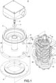
- the rotary screw compressor 10 comprises a compressor assembly 1 and a drive motor assembly 2.
- the compressor assembly 1 comprises a compressor housing 11 installed in the compressor housing 11, and a first screw rotor 12 and a second screw rotor 13 engaged with each other, and an end of the first screw rotor 12 has an engaging end 121.
- the compressor housing 11 has a compression chamber 111 for accommodating the first screw rotor 12 and the second screw rotor 13.
- both ends of the first screw rotor 12 and the second screw rotor 13 have an air suction end 14 and an air exhaust end 15 respectively, and a sealing line L is defined between the air suction end 14 and the air exhaust end 15, and the area between the air exhaust end 15 and the sealing line L is defined as a compression operation area, and the area between the air suction end 14 and the sealing line L is defined as an initial compression operation area.
- first screw rotor 12 and the second screw rotor 13 has a first spiral groove 17 and a second spiral groove 18 counting from the air suction end 14, and the initial compression area is substantially disposed between the air suction end 14 and the second spiral groove 18.
- the drive motor assembly 2 comprises a motor housing 21, a motor stator 23, a centering bushing 24 and a motor rotor 22 installed in the motor housing 21, and the motor stator 23 is installed to an outer side of the motor rotor 22, and the motor stator 23 drives the motor rotor 22 to rotate by the principle of electromagnetic induction, and the centering bushing 24 is coupled to the motor rotor 22 in a tight fit manner, and has an end for accommodating the engaging end 121 in the tight-fit manner, so that the motor rotor 22 can drive the centering bushing 24 to rotate, and the centering bushing 24 can drive the engaging end 121 to rotate, so that the motor rotor 22 can drive the first screw rotor 12 to rotate through the centering bushing 24 and the engaging end 121.
- the motor housing 21 has an inner surface 211 and an outer surface 212, and an air gap of 1mm is maintained between the motor rotor 22 and the motor stator 23, but the size is not limited to 1mm.
- the centering bushing 24 is passed and installed into the thermally expanded motor rotor 22, and the motor rotor 22 will be bounded tightly and naturally with the centering bushing 24 after cooling, and the engaging end 121 is passed and installed into the thermally expanded centering bushing 24, and the centering bushing 24 will be bounded tightly and naturally with the engaging end 121 after cooling.
- the rotary screw compressor 10 of this disclosure further comprises an insert key 3, and the engaging end 121 has a first snap slot 122 formed along the axial direction thereof, and the centering bushing 24 has a second snap slot 241 formed along the axial direction thereof, and the insert key 3 is snapped into the first snap slot 122 and the second snap slot 241, and the first screw rotor 12 and the centering bushing 24 use the insert key 3 to perform a mechanical transmission, and an axial hole for the interference fit of the concentric alignment, so that the centering bushing 24 and the first screw rotor 12 can be fixed securely with each other and rotated jointly.
- the rotary screw compressor 10 of this disclosure further comprises a gasket 4 and a bolt 5, and the engaging end 121 has an extremity 123 and a stop block 124 extending therefrom, and the extremity 123 has a first through hole 1231, and the gasket 4 has a second through hole 41, and a protrusion 242 is extended from an inner periphery of the centering bushing 24, and the bolt 5 is locked into the first through hole 1231 and the second through hole 41, and the gasket 4 is clamped between the extremity 123, the protrusion 242 and the bolt 5, and the stop block 124 and the centering bushing 24 block and position with each other, so that the engaging end 121 has an end for blocking and limiting a position through the gasket 4 and the other end for blocking and limiting a position through the stop block 124, so as to connect the engaging end 121 into the centering bushing 24 stably.
- the rotary screw compressor 10 of the invention further comprises a filling tube 61, a storage tank 62 and a guide tube 7, and the motor housing 21 has a cooling passage 213 formed between the inner surface 211 and the outer surface 212, and the filling tube 61 has an end just communicating to the storage tank 62 only and the other end just communicating to the cooling passage 213 only, and the guide tube 7 has an end just communicating to the cooling passage 213 only and the other end just communicating to the compression chamber 111 only, and a coolant sequentially flows through the liquid tube 6, the cooling passage 213 and the guide tube 7 to the compression chamber 111, and the compressor housing 11 has a first opening 112 between the compression chamber 111 and the guide tube 7, and the first opening 112 is disposed between the first spiral groove 17 and the second spiral groove 18 of any one of the first screw rotor 12 and the second screw rotor 13.
- the first opening 112 of the compressor housing 11 is situated in the initial compression operation area, which is at a low to
- the storage tank 62 is a high-pressure tank, and the air pressure within the storage tank 62 is greater than the air pressure between the first spiral groove 17 and the second spiral groove 18 of any one of the first screw rotor 12 and the second screw rotor 13.
- the air pressure within the storage tank 62 is greater than the air pressure of the aforementioned initial compression operation area, so that the high-pressure coolant can be delivered sequentially from the storage tank 62, the filling tube 61, the cooling passage 213, the guide tube 7, and the first opening 112 to the compression chamber 111 by pressure difference , and finally the coolant within the compression chamber 111 will be circulated to the storage tank 62 through the tubes, so that the process of pumping the coolant and the pump component are omitted, and the structure and the volume of the rotary screw compressor 10 is simplified as well.
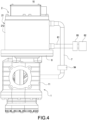
- the cooling passage 213 of this embodiment is a spiral flow channel 2131, and the spiral flow channel 2131 surrounds the outer periphery of the motor housing 21, and the motor housing 21 has a second opening 215 and a third opening 216 sequentially arranged in a direction away from the compressor assembly 1.
- the position of the third opening 216 is higher than the position of the second opening 215, and the second opening 215 is coupled between an end of the spiral flow channel 2131 and the filling tube 61, and the third opening 216 is coupled between the other end of the spiral flow channel 2131 and the guide tube 7, so that the coolant within the cooling passage 213 can flow upwardly from the bottom.
- the coolant within the cooling passage 213 flows upwardly from the bottom provides a uniform flow that facilitates the cooling of the drive motor assembly 2 and prevents the deterioration of the mixed air.
- the rotary screw compressor 10 of this disclosure further comprises an annular positioning plate 8, and the motor housing 21 has a connection port 214 configured to be corresponsive to the compressor housing 11, and a bearing seat 16 extends from an end of the compressor housing 11, and the annular positioning plate 8 is sheathed on the outer periphery of the bearing seat 16 and installed to the inner circumference of the connection port 214 in an transition-fit manner. Since the center of the annular positioning plate 8 can be aligned precisely with the axis of the bearing seat 16 and the center of the connection port 214 easily, and the annular positioning plate 8 can be detachably sealed onto the connection port 214, so that the annular positioning plate 8 has the features of convenient installation, optimal concentricity, and high sealing and anti-leaking functions.
- the tolerance between the annular positioning plate 8, the bearing seat 16, and the connection port 214 is small, and if a force greater than a predetermined external force is exerted onto the annular positioning plate 8, the annular positioning plate 8 will be sheathed on the bearing seat 16 tightly and fixed into the connection port 214 securely.
- the rotary screw compressor 10 of this disclosure further comprises two first bearings 91 and two second bearings 92 installed in the compressor housing 11, and the two first bearings 91 are disposed on both ends of the first screw rotor 12 respectively, so that both ends of the first screw rotor 12 can be positioned in the compressor housing 11 by the two first bearings 91, and the two second bearings 92 are disposed on both ends of the second screw rotor 13 respectively, so that both ends of the second screw rotor 13 can be positioned in the compressor housing 11 by the two second bearings 92, and one of the first bearings 91 is clamped between the bearing seat 16 and the first screw rotor 12. Since the bearing seat 16 is extended from and integrally formed with the compressor housing 11, the rotary screw compressor 10 is simplified and compact.
- the rotary screw compressor 10 of this disclosure further comprises a filter 94 and a cooler 95, wherein the cooler 95 is installed at the filling tube 61, and the filter 94 is installed at the guide tube 7, and the filter 94 is provided for filtering impurities of the coolant and the cooler 95 for provided for cooling the coolant, so that the temperature of the coolant is low.
- the motor rotor 22 of the rotary screw compressor 10 is provided for connecting the engaging end 121 of the first screw rotor 12 directly through the centering bushing 24, so that the first screw rotor 12 can drive the second screw rotor 13 to rotate for the operation of the compressor assembly 1.
- This centering bushing 24 is provided to substitute the conventional drive shaft, so that both ends of the centering bushing 24 no longer require any bearing or bearing driving part, so as to reduce the accommodation space and the overall volume of the rotary screw compressor 10.
- the structure of the rotary screw compressor 10 is simplified as well.
- the centering bushing 24 require no bearing or bearing driving part, so that it is not necessary to lubricate the coolant at both ends of the centering bushing 24, and the filling tube 61 just communicates to the cooling passage 213 only, and the guide tube 7 has an end just communicating to the cooling passage 213 only and the other end just communicating to the compression chamber 111 only, so that the coolant can flow through the motor housing 21 in order to cool the drive motor assembly 2, and the coolant does not need to flow through both ends of the centering bushing 24, so as to prevent the coolant from permeating from both ends of the centering bushing 24 into the motor housing 21, and prevent the motor rotor 22 and the motor stator 23 from being overheated or damaged, and the dirt in the motor housing 21 will not enter into the compression chamber 111, so as to extend the service life of the drive motor assembly 1.
- the conventional drive shaft drives the spiral rotor to rotate by the bearing driving part, so that there will be a transmission loss.
- the motor rotor 22 of this disclosure directly connects the centering bushing 24 with the engaging end 121 of the first screw rotor 12 to reduce the transmission loss.
- the annular positioning plate 8 is installed between the compressor housing 11 and the motor housing 21.
- the annular positioning plate 8 is provided to integrate two independent assemblies (which are the compressor assembly 1 and the drive motor assembly 2) into a whole compressor assembly, so as to further reduce the volume of the rotary screw compressor 10.
- compressor assembly 1 and the drive motor assembly 2 according to the invention are disposed in upright fashion with respect to each other.
- the engaging end 121 has a length ranging from one-third to half of the centering bushing 24, so that the mass of the centering bushing 24 is reduced and the center of gravity of the whole motor rotor 22 is lowered to prevent resonance occurred during the rotation of the motor rotor 22.
- FIG. 7 An alternative solution of the cooling passage 213 according to the invention is shown in FIG. 7 .
- the cooling passage 213 comprises two circular flow channels 2132 and a plurality of straight flow channels 2133 coupled between the two circular flow channels 2132, and the plurality of straight flow channels 2133 is configured to be parallel to the axial direction of the motor housing 21, and the motor housing 21 has a second opening 215' and a third opening 216' arranged sequentially in a direction away from the compressor assembly 1.
- the position of the third opening 216' is higher than the position of the second opening 215', and the second opening 215' is coupled between one of the circular flow channels 2132 and the filling tube 61, and the third opening 216' is coupled between the other circular flow channel 2132 and the guide tube 7, so that the coolant at the cooling passage 213 flows upwardly from the bottom to achieve the same effects and functions as those of the previous solution illustrated in FIGS. 1 to 6 .
Landscapes
- Engineering & Computer Science (AREA)
- Mechanical Engineering (AREA)
- General Engineering & Computer Science (AREA)
- Power Engineering (AREA)
- Applications Or Details Of Rotary Compressors (AREA)
Claims (8)
- Ein rotierender Schraubenkompressor, bestehend aus:Einer Kompressorbaugruppe (1), umfassend ein Kompressorgehäuse (11), einen ersten Schraubenrotor (12) und einen zweiten Schraubenrotor (13), die in dem Kompressorgehäuse (11) installiert sind und miteinander in Eingriff stehen, wobei ein Ende des ersten Schraubenrotors (12) ein Eingriffsende (121) aufweist, wobei das Kompressorgehäuse (11) eine Kompressionskammer (111) zur Aufnahme des ersten Schraubenrotors (12) und des zweiten Schraubenrotors (13) aufweist, beide Enden des ersten Schraubenrotors (12) und des zweiten Schraubenrotors (13) jeweils ein Luftansaugende (14) ein Luftauslassende (15) haben, und der erste Schraubenrotor (12) und der zweite Schraubenrotor (13) jeweils eine erste Spiralnut (17) und eine zweite Spiralnut (18) von dem Luftansaugende (14) haben;Einer Antriebsmotoranordnung (2) mit einem Motorgehäuse (21) und einem Motorrotor (22), einem Motorstator (23) und einer Zentrierbuchse (24), die in dem Motorgehäuse (21) installiert sind, wobei der Motorstator (23) in dem Motorrotor (22) installiert ist und in der Lage ist, den Motorrotor (22) zur Drehung anzutreiben, wobei die Zentrierbuchse (24) mit dem Innenumfang des Motorrotors (22) gekoppelt ist und ein Ende zur Aufnahme des Eingriffsendes (121) aufweist, so dass der Motorrotor (22) den ersten Schraubenrotor (12) antreiben kann, um sich durch die Zentrierbuchse (24) und das Eingriffsende (121) zu drehen, und das Motorgehäuse (21) eine Innenfläche (211), eine Außenfläche (212) und einen Kühlkanal (213) aufweist, der zwischen der Innenfläche (211) und der Außenfläche (212) angeordnet ist;ein Füllrohr (61);einen Vorratstank (62); undein Führungsrohr (7);wobei das Füllrohr (61) ein Ende hat, das mit dem Vorratsbehälter (62) in Verbindung steht, und das andere Ende mit dem Kühlkanal (213) in Verbindung steht, wobei das Führungsrohr (7) ein Ende hat, das mit dem Kühlkanal (213) in Verbindung steht, und das andere Ende mit der Kompressionskammer (111) in Verbindung steht, und dadurch gekennzeichnet, dass das Kompressorgehäuse (11) eine erste Öffnung (112) aufweist, die zwischen die Kompressionskammer (111) und das Führungsrohr (7) gekoppelt ist, wobei die erste Öffnung (112) zwischen der ersten Spiralnut (17) und der zweiten Spiralnut (18) des ersten Schraubenrotors (12) oder des zweiten Schraubenrotors (13) angeordnet ist, der Kühlkanal (213) ein spiralförmiger Strömungskanal (2131) ist, der spiralförmige Strömungskanal (2131) den Außenumfang des Motorgehäuses (21) umgibt, das Motorgehäuse (21) eine zweite Öffnung (215) und eine dritte Öffnung (216) aufweist, die aufeinanderfolgend in einer Richtung weg von der Kompressorbaugruppe (1) angeordnet sind, die zweite Öffnung (215) zwischen ein Ende des spiralförmiger Strömungskanals (2131) und das Füllrohr (61) gekoppelt ist, und die dritte Öffnung (216) zwischen das andere Ende des spiralförmigen Strömungskanals (2131) und das Führungsrohr (7) gekoppelt ist;wobei die Kompressorbaugruppe (1) und die Antriebsmotoreinheit (2) aufrecht zueinander angeordnet sind,und der Vorratstank (62) einen Innendruck aufweist, der größer ist als der Luftdruck zwischen der ersten Spiralnut (17) und der zweiten Spiralnut (18) des ersten Schraubenrotors (12) oder des zweiten Schraubenrotors (13), so dass ein Kühlmittel nacheinander aus dem Vorratstank (62), dem Füllrohr (61), dem Kühlkanal (213), dem Führungsrohr (7) und der ersten Öffnung (112) durch Druckdifferenz in den Kompressionsraum (111) gefördert werden kann, wobei das Kühlmittel im Kühlkanal (213) nach oben fließen kann.
- Ein rotierender Schraubenkompressor, bestehend aus:Kompressorbaugruppe (1), umfassend ein Kompressorgehäuse (11), einen ersten Schraubenrotor (12) und einen zweiten Schraubenrotor (13), die in dem Kompressorgehäuse (11) installiert sind und miteinander in Eingriff stehen, wobei ein Ende des ersten Schraubenrotors (12) ein Eingriffsende (121) aufweist, wobei das Kompressorgehäuse (11) eine Kompressionskammer (111) zur Aufnahme des ersten Schraubenrotors (12) und des zweiten Schraubenrotors (13) aufweist, beide Enden des ersten Schraubenrotors (12) und des zweiten Schraubenrotors (13) jeweils ein Luftansaugende (14) ein Luftauslassende (15) haben, und der erste Schraubenrotor (12) und der zweite Schraubenrotor (13) jeweils eine erste Spiralnut (17) eine zweite Spiralnut (18) von dem Luftansaugende (14) haben;Antriebsmotoranordnung (2) mit einem Motorgehäuse (21), einem Motorrotor (22), einem Motorstator (23) und einer Zentrierbuchse (24), die in dem Motorgehäuse (21) installiert ist, wobei der Motorstator (23) in dem Motorrotor (22) installiert ist und in der Lage ist, den Motorrotor (22) zur Drehung anzutreiben, wobei die Zentrierbuchse (24) mit dem Innenumfang des Motorrotors (22) gekoppelt ist und ein Ende zur Aufnahme des Eingriffsendes (121) aufweist, so dass der Motorrotor (22) den ersten Schraubenrotor (12) antreiben kann, um sich durch die Zentrierbuchse (24) und das Eingriffsende (121) zu drehen, wobei das Motorgehäuse (21) eine Innenfläche (211), eine Außenfläche (212) und einen Kühlkanal (213) aufweist, der zwischen der Innenfläche (211) und der Außenfläche (212) angeordnet ist;ein Füllrohr (61);einen Vorratstank (62); undein Führungsrohr (7);wobei das Füllrohr (61) ein Ende hat, das mit dem Vorratsbehälter (62) in Verbindung steht, und das andere Ende mit dem Kühlkanal (213) in Verbindung steht, wobei das Führungsrohr (7) ein Ende hat, das mit dem Kühlkanal (213) in Verbindung steht, und das andere Ende mit der Kompressionskammer (111) in Verbindung steht, dadurch gekennzeichnet, dass das Kompressorgehäuse (11) eine erste Öffnung (112) aufweist, die zwischen die Kompressionskammer (111) und das Führungsrohr (7) gekoppelt ist, wobei die erste Öffnung (112) zwischen der ersten Spiralnut (17) und der zweiten Spiralnut (18) des ersten Schraubenrotors (12) oder des zweiten Schraubenrotors (13) angeordnet ist, der Kühlkanal (213) zwei kreisförmige Strömungskanäle (2132) und eine Vielzahl von geraden Strömungskanälen (2133) umfasst, die zwischen den beiden kreisförmigen Strömungskanälen (2132) angeschlossen sind, wobei sich die Vielzahl von geraden Strömungskanälen (2133) in einer Richtung parallel zur Achse des Motorgehäuses (21) erstreckt, das Motorgehäuse (21) eine zweite Öffnung (215') und eine dritte Öffnung (216') aufweist, die aufeinanderfolgend in einer Richtung weg von der Kompressorbaugruppe (1) angeordnet sind, die zweite Öffnung (215') zwischen einem der kreisförmigen Strömungskanäle (2132) und dem Füllrohr (61) gekoppelt ist, und die dritte Öffnung (216') zwischen dem anderen kreisförmigen Strömungskanal (2132) und dem Führungsrohr (7) gekoppelt ist;wobei die Kompressorbaugruppe (1) und die Antriebsmotoranordnung (2) aufrecht zueinander angeordnet sind und der Vorratsbehälter (62) einen Innendruck aufweist, der größer ist als der Luftdruck zwischen der ersten Spiralnut (17) und der zweiten Spiralnut (18) des ersten Schraubenrotors (12) oder des zweiten Schraubenrotors (13), so dass ein Kühlmittel nacheinander von dem Vorratsbehälter (62), dem Füllrohr (61), dem Kühlkanal (213), dem Führungsrohr (7) und der ersten Öffnung (112) zu der Kompressionskammer (111) durch Druckunterschied geliefert werden kann, wobei das Kühlmittel innerhalb des Kühlkanals (213) nach oben fließen kann.
- Der rotierende Schraubenkompressor nach Anspruch 1 oder 2, wobei das Eingriffsende (121) eine Länge (a) im Bereich von einem Drittel bis zur Hälfte der Länge der Zentrierbuchse (24) aufweist.
- Der Rotierende Schraubenkompressor nach Anspruch 1 oder 2, der ferner einen Einsatzkeil (3) umfasst, wobei das Eingriffsende (121) einen ersten Schnappschlitz (122) aufweist, der entlang seiner Achse ausgebildet ist, und die Zentrierbuchse (24) einen zweiten Schnappschlitz (241) aufweist, der entlang ihrer Achse ausgebildet ist, und der Einsatzkeil (3) in den ersten Schnappschlitz (122) und den zweiten Schnappschlitz (241) eingeschnappt ist.
- Der Rotierende Schraubenkompressor nach Anspruch 1 oder 2, ferner mit einer Dichtung (4) und einem Bolzen (5), wobei das Eingriffsende (121) ein Ende (123) und einen sich davon erstreckenden Anschlagblock (124) aufweist und das Ende (123) ein erstes Durchgangsloch (1231) und die Dichtung (4) ein zweites Durchgangsloch (41) aufweist, und ein Vorsprung (242) von einem inneren Umfang der Zentrierbuchse (24) vorsteht, und der Bolzen (5) mit dem ersten Durchgangsloch (1231) und dem zweiten Durchgangsloch (41) verriegelt ist, und die Dichtung (4) zwischen dem Ende (123), dem Vorsprung (242) und dem Bolzen (5) eingeklemmt ist, und der Anschlagblock (124) und die Zentrierbuchse (24) einander blockieren und positionieren.
- Der rotierende Schraubenkompressor nach Anspruch 1 oder 2, ferner mit einem Filter (94) und einem Kühler (95), wobei der Kühler (95) am Füllrohr (61) und der Filter (94) am Führungsrohr (7) angebracht ist.
- Der rotierende Schraubenkompressor nach Anspruch 1 oder 2, ferner mit einer ringförmigen Positionierplatte (8), wobei das Motorgehäuse (21) eine mit dem Kompressorgehäuse (11) korrespondierende Anschlussöffnung (214) und einen von einem Ende des Kompressorgehäuses (11) ausgehenden Lagersitz (16) aufweist, und die ringförmige Positionierplatte (8) am Außenumfang des Lagersitzes (16) ummantelt ist und übergangsweise in den Innenumfang des Anschlussstutzens (214) übergeht, und die ringförmige Positionierplatte (8) lösbar auf den Anschlussstutzen (214) abgedichtet ist.
- Der rotierende Schraubenkompressor nach Anspruch 7, ferner mit zwei ersten Lagern (91) und zwei zweiten Lagern (92), die in dem Kompressorgehäuse (11) untergebracht sind, wobei die beiden ersten Lager (91) jeweils an beiden Enden des ersten Schraubenrotors (12) und die beiden zweiten Lager (92) jeweils an beiden Enden des zweiten Schraubenrotors (13) angeordnet sind und eines der ersten Lager (91) zwischen dem Lagersitz (16) und dem ersten Schraubenrotor (12) eingeklemmt ist.
Applications Claiming Priority (1)
| Application Number | Priority Date | Filing Date | Title |
|---|---|---|---|
| CN201910421109.5A CN111963427B (zh) | 2019-05-20 | 2019-05-20 | 螺旋式压缩机 |
Publications (3)
| Publication Number | Publication Date |
|---|---|
| EP3741996A1 EP3741996A1 (de) | 2020-11-25 |
| EP3741996C0 EP3741996C0 (de) | 2024-09-18 |
| EP3741996B1 true EP3741996B1 (de) | 2024-09-18 |
Family
ID=70227897
Family Applications (1)
| Application Number | Title | Priority Date | Filing Date |
|---|---|---|---|
| EP20168553.4A Active EP3741996B1 (de) | 2019-05-20 | 2020-04-07 | Rotierender schraubenkompressor |
Country Status (4)
| Country | Link |
|---|---|
| US (1) | US11326596B2 (de) |
| EP (1) | EP3741996B1 (de) |
| CN (1) | CN111963427B (de) |
| TW (1) | TWI705186B (de) |
Families Citing this family (6)
| Publication number | Priority date | Publication date | Assignee | Title |
|---|---|---|---|---|
| CN114109833A (zh) * | 2021-12-30 | 2022-03-01 | 石家庄通安机械有限公司 | 螺杆压缩机 |
| US12398738B2 (en) * | 2022-01-10 | 2025-08-26 | Parker-Hannifin Corporation | Integrated assembly of an electric motor, hydraulic pump, and electronic drive device and associated cooling configuration |
| CN114635852A (zh) * | 2022-03-18 | 2022-06-17 | 江苏新凯晟机械设备有限公司 | 一种具有清洁功能的空压机 |
| CN115076107B (zh) * | 2022-07-06 | 2023-06-23 | 杭州千岛泵业有限公司 | 一种悬臂立式螺杆真空泵 |
| CN115711234B (zh) * | 2022-12-12 | 2025-11-14 | 江苏新凯晟机械设备有限公司 | 一种封闭导通式空气压缩机排气调节结构 |
| WO2025221762A1 (en) * | 2024-04-15 | 2025-10-23 | Tyco Fire & Security Gmbh | Vaned diffuser for a mixed flow compressor |
Citations (2)
| Publication number | Priority date | Publication date | Assignee | Title |
|---|---|---|---|---|
| US3922114A (en) * | 1974-07-19 | 1975-11-25 | Dunham Bush Inc | Hermetic rotary helical screw compressor with improved oil management |
| EP1366297B1 (de) * | 2001-03-06 | 2006-09-27 | Atlas Copco Airpower, Naamloze Vennootschap | Wassereingespritzter schraubenverdichter |
Family Cites Families (12)
| Publication number | Priority date | Publication date | Assignee | Title |
|---|---|---|---|---|
| TW420255U (en) * | 2000-05-26 | 2001-01-21 | Ind Tech Res Inst | Composite double helical rotor device |
| FR2812040B1 (fr) * | 2000-07-18 | 2003-02-07 | Cit Alcatel | Carter monobloc pour pompe a vide |
| GB2376505B (en) | 2001-06-11 | 2003-12-17 | Compair Uk Ltd | Improvements in screw compressors |
| KR100408153B1 (ko) * | 2001-08-14 | 2003-12-01 | 주식회사 우성진공 | 드라이 진공펌프 |
| US20070241627A1 (en) * | 2006-04-12 | 2007-10-18 | Sullair Corporation | Lubricant cooled integrated motor/compressor design |
| WO2017018902A1 (ru) | 2015-07-28 | 2017-02-02 | Юрий Борисович СОКОЛОВ | Светодиодная лампа |
| JP6476093B2 (ja) * | 2015-08-28 | 2019-02-27 | 株式会社神戸製鋼所 | スクリュ圧縮機 |
| JP6982380B2 (ja) * | 2016-03-08 | 2021-12-17 | コベルコ・コンプレッサ株式会社 | スクリュ圧縮機 |
| CN205565990U (zh) * | 2016-04-01 | 2016-09-07 | 苏州汇川技术有限公司 | 一种设备与电机的安装结构 |
| DE102016011503A1 (de) * | 2016-09-21 | 2018-03-22 | Knorr-Bremse Systeme für Nutzfahrzeuge GmbH | System für ein Nutzfahrzeug umfassend einen Schraubenkompressor sowie einen Elektromotor |
| CN106401976A (zh) * | 2016-10-21 | 2017-02-15 | 珠海格力电器股份有限公司 | 空调器及其螺杆压缩机 |
| CN208734541U (zh) * | 2018-09-06 | 2019-04-12 | 苏州通润驱动设备股份有限公司 | 一种双级螺杆压缩机 |
-
2019
- 2019-05-20 CN CN201910421109.5A patent/CN111963427B/zh active Active
- 2019-05-28 TW TW108118450A patent/TWI705186B/zh active
-
2020
- 2020-04-01 US US16/837,750 patent/US11326596B2/en active Active
- 2020-04-07 EP EP20168553.4A patent/EP3741996B1/de active Active
Patent Citations (2)
| Publication number | Priority date | Publication date | Assignee | Title |
|---|---|---|---|---|
| US3922114A (en) * | 1974-07-19 | 1975-11-25 | Dunham Bush Inc | Hermetic rotary helical screw compressor with improved oil management |
| EP1366297B1 (de) * | 2001-03-06 | 2006-09-27 | Atlas Copco Airpower, Naamloze Vennootschap | Wassereingespritzter schraubenverdichter |
Also Published As
| Publication number | Publication date |
|---|---|
| TWI705186B (zh) | 2020-09-21 |
| US11326596B2 (en) | 2022-05-10 |
| EP3741996A1 (de) | 2020-11-25 |
| CN111963427B (zh) | 2022-06-14 |
| TW202043622A (zh) | 2020-12-01 |
| US20200370554A1 (en) | 2020-11-26 |
| EP3741996C0 (de) | 2024-09-18 |
| CN111963427A (zh) | 2020-11-20 |
Similar Documents
| Publication | Publication Date | Title |
|---|---|---|
| EP3741996B1 (de) | Rotierender schraubenkompressor | |
| KR102013510B1 (ko) | 스크류 압축기 | |
| CN112483388B (zh) | 共旋转式压缩机 | |
| US9197115B2 (en) | Electric machine cooling | |
| US6986648B2 (en) | Electric pump | |
| EP1302704B1 (de) | Eingetauchte, elektrische Fluidpumpe | |
| US12230777B2 (en) | Temperature control device for a battery bank module | |
| US20220333597A1 (en) | Integrated screw-spindle coolant pump | |
| JP2020513722A (ja) | 開放冷却アセンブリに組み合わされた封入冷却アセンブリが設けられた電気機械 | |
| KR20170068403A (ko) | 전기 모터 구동식 액체 펌프 | |
| US20130043747A1 (en) | Electric Machine Cooling | |
| TWI683060B (zh) | 無油螺旋壓縮機 | |
| EP4124756B1 (de) | Verbesserte schraubenspindelpumpe, insbesondere für kühlsysteme | |
| US20160369796A1 (en) | Integrated Motor-Pump | |
| US11739750B2 (en) | Gear pump | |
| CN101356375B (zh) | 流体泵 | |
| JPH02173393A (ja) | 軸流ポンプの軸推力軽減装置 | |
| CN223414728U (zh) | 一种电机结构 | |
| US20250059970A1 (en) | Automotive electric liquid pump | |
| CN220527823U (zh) | 旋翼驱动电机及飞行器 | |
| CN223062640U (zh) | 一种集成电子油泵 | |
| CN119636448A (zh) | 增程器 | |
| CN119062571A (zh) | 一种电动泵 | |
| HK1234808B (zh) | 电动机驱动的流体泵 |
Legal Events
| Date | Code | Title | Description |
|---|---|---|---|
| PUAI | Public reference made under article 153(3) epc to a published international application that has entered the european phase |
Free format text: ORIGINAL CODE: 0009012 |
|
| STAA | Information on the status of an ep patent application or granted ep patent |
Free format text: STATUS: THE APPLICATION HAS BEEN PUBLISHED |
|
| AK | Designated contracting states |
Kind code of ref document: A1 Designated state(s): AL AT BE BG CH CY CZ DE DK EE ES FI FR GB GR HR HU IE IS IT LI LT LU LV MC MK MT NL NO PL PT RO RS SE SI SK SM TR |
|
| AX | Request for extension of the european patent |
Extension state: BA ME |
|
| STAA | Information on the status of an ep patent application or granted ep patent |
Free format text: STATUS: REQUEST FOR EXAMINATION WAS MADE |
|
| 17P | Request for examination filed |
Effective date: 20201225 |
|
| RBV | Designated contracting states (corrected) |
Designated state(s): AL AT BE BG CH CY CZ DE DK EE ES FI FR GB GR HR HU IE IS IT LI LT LU LV MC MK MT NL NO PL PT RO RS SE SI SK SM TR |
|
| STAA | Information on the status of an ep patent application or granted ep patent |
Free format text: STATUS: EXAMINATION IS IN PROGRESS |
|
| 17Q | First examination report despatched |
Effective date: 20221103 |
|
| GRAP | Despatch of communication of intention to grant a patent |
Free format text: ORIGINAL CODE: EPIDOSNIGR1 |
|
| STAA | Information on the status of an ep patent application or granted ep patent |
Free format text: STATUS: GRANT OF PATENT IS INTENDED |
|
| INTG | Intention to grant announced |
Effective date: 20240523 |
|
| GRAS | Grant fee paid |
Free format text: ORIGINAL CODE: EPIDOSNIGR3 |
|
| GRAA | (expected) grant |
Free format text: ORIGINAL CODE: 0009210 |
|
| STAA | Information on the status of an ep patent application or granted ep patent |
Free format text: STATUS: THE PATENT HAS BEEN GRANTED |
|
| AK | Designated contracting states |
Kind code of ref document: B1 Designated state(s): AL AT BE BG CH CY CZ DE DK EE ES FI FR GB GR HR HU IE IS IT LI LT LU LV MC MK MT NL NO PL PT RO RS SE SI SK SM TR |
|
| REG | Reference to a national code |
Ref country code: GB Ref legal event code: FG4D |
|
| REG | Reference to a national code |
Ref country code: CH Ref legal event code: EP |
|
| REG | Reference to a national code |
Ref country code: IE Ref legal event code: FG4D |
|
| REG | Reference to a national code |
Ref country code: DE Ref legal event code: R096 Ref document number: 602020037796 Country of ref document: DE |
|
| U01 | Request for unitary effect filed |
Effective date: 20240918 |
|
| U07 | Unitary effect registered |
Designated state(s): AT BE BG DE DK EE FI FR IT LT LU LV MT NL PT RO SE SI Effective date: 20240930 |
|
| PG25 | Lapsed in a contracting state [announced via postgrant information from national office to epo] |
Ref country code: NO Free format text: LAPSE BECAUSE OF FAILURE TO SUBMIT A TRANSLATION OF THE DESCRIPTION OR TO PAY THE FEE WITHIN THE PRESCRIBED TIME-LIMIT Effective date: 20241218 |
|
| PG25 | Lapsed in a contracting state [announced via postgrant information from national office to epo] |
Ref country code: GR Free format text: LAPSE BECAUSE OF FAILURE TO SUBMIT A TRANSLATION OF THE DESCRIPTION OR TO PAY THE FEE WITHIN THE PRESCRIBED TIME-LIMIT Effective date: 20241219 |
|
| PG25 | Lapsed in a contracting state [announced via postgrant information from national office to epo] |
Ref country code: HR Free format text: LAPSE BECAUSE OF FAILURE TO SUBMIT A TRANSLATION OF THE DESCRIPTION OR TO PAY THE FEE WITHIN THE PRESCRIBED TIME-LIMIT Effective date: 20240918 |
|
| PG25 | Lapsed in a contracting state [announced via postgrant information from national office to epo] |
Ref country code: RS Free format text: LAPSE BECAUSE OF FAILURE TO SUBMIT A TRANSLATION OF THE DESCRIPTION OR TO PAY THE FEE WITHIN THE PRESCRIBED TIME-LIMIT Effective date: 20241218 |
|
| PG25 | Lapsed in a contracting state [announced via postgrant information from national office to epo] |
Ref country code: RS Free format text: LAPSE BECAUSE OF FAILURE TO SUBMIT A TRANSLATION OF THE DESCRIPTION OR TO PAY THE FEE WITHIN THE PRESCRIBED TIME-LIMIT Effective date: 20241218 Ref country code: NO Free format text: LAPSE BECAUSE OF FAILURE TO SUBMIT A TRANSLATION OF THE DESCRIPTION OR TO PAY THE FEE WITHIN THE PRESCRIBED TIME-LIMIT Effective date: 20241218 Ref country code: HR Free format text: LAPSE BECAUSE OF FAILURE TO SUBMIT A TRANSLATION OF THE DESCRIPTION OR TO PAY THE FEE WITHIN THE PRESCRIBED TIME-LIMIT Effective date: 20240918 Ref country code: GR Free format text: LAPSE BECAUSE OF FAILURE TO SUBMIT A TRANSLATION OF THE DESCRIPTION OR TO PAY THE FEE WITHIN THE PRESCRIBED TIME-LIMIT Effective date: 20241219 |
|
| PG25 | Lapsed in a contracting state [announced via postgrant information from national office to epo] |
Ref country code: IS Free format text: LAPSE BECAUSE OF FAILURE TO SUBMIT A TRANSLATION OF THE DESCRIPTION OR TO PAY THE FEE WITHIN THE PRESCRIBED TIME-LIMIT Effective date: 20250118 |
|
| PG25 | Lapsed in a contracting state [announced via postgrant information from national office to epo] |
Ref country code: SM Free format text: LAPSE BECAUSE OF FAILURE TO SUBMIT A TRANSLATION OF THE DESCRIPTION OR TO PAY THE FEE WITHIN THE PRESCRIBED TIME-LIMIT Effective date: 20240918 |
|
| PG25 | Lapsed in a contracting state [announced via postgrant information from national office to epo] |
Ref country code: ES Free format text: LAPSE BECAUSE OF FAILURE TO SUBMIT A TRANSLATION OF THE DESCRIPTION OR TO PAY THE FEE WITHIN THE PRESCRIBED TIME-LIMIT Effective date: 20240918 |
|
| PG25 | Lapsed in a contracting state [announced via postgrant information from national office to epo] |
Ref country code: CZ Free format text: LAPSE BECAUSE OF FAILURE TO SUBMIT A TRANSLATION OF THE DESCRIPTION OR TO PAY THE FEE WITHIN THE PRESCRIBED TIME-LIMIT Effective date: 20240918 Ref country code: PL Free format text: LAPSE BECAUSE OF FAILURE TO SUBMIT A TRANSLATION OF THE DESCRIPTION OR TO PAY THE FEE WITHIN THE PRESCRIBED TIME-LIMIT Effective date: 20240918 |
|
| PG25 | Lapsed in a contracting state [announced via postgrant information from national office to epo] |
Ref country code: SK Free format text: LAPSE BECAUSE OF FAILURE TO SUBMIT A TRANSLATION OF THE DESCRIPTION OR TO PAY THE FEE WITHIN THE PRESCRIBED TIME-LIMIT Effective date: 20240918 |
|
| U20 | Renewal fee for the european patent with unitary effect paid |
Year of fee payment: 6 Effective date: 20250430 |
|
| PLBE | No opposition filed within time limit |
Free format text: ORIGINAL CODE: 0009261 |
|
| STAA | Information on the status of an ep patent application or granted ep patent |
Free format text: STATUS: NO OPPOSITION FILED WITHIN TIME LIMIT |
|
| 26N | No opposition filed |
Effective date: 20250619 |
|
| REG | Reference to a national code |
Ref country code: CH Ref legal event code: H13 Free format text: ST27 STATUS EVENT CODE: U-0-0-H10-H13 (AS PROVIDED BY THE NATIONAL OFFICE) Effective date: 20251125 |
|
| PG25 | Lapsed in a contracting state [announced via postgrant information from national office to epo] |
Ref country code: MC Free format text: LAPSE BECAUSE OF FAILURE TO SUBMIT A TRANSLATION OF THE DESCRIPTION OR TO PAY THE FEE WITHIN THE PRESCRIBED TIME-LIMIT Effective date: 20240918 |
|
| GBPC | Gb: european patent ceased through non-payment of renewal fee |
Effective date: 20250407 |
|
| PG25 | Lapsed in a contracting state [announced via postgrant information from national office to epo] |
Ref country code: GB Free format text: LAPSE BECAUSE OF NON-PAYMENT OF DUE FEES Effective date: 20250407 |
|
| PG25 | Lapsed in a contracting state [announced via postgrant information from national office to epo] |
Ref country code: CH Free format text: LAPSE BECAUSE OF NON-PAYMENT OF DUE FEES Effective date: 20250430 |