EP3741965B1 - Turbomaschine, die einen ringförmigen befestigungsflansch umfasst - Google Patents
Turbomaschine, die einen ringförmigen befestigungsflansch umfasst Download PDFInfo
- Publication number
- EP3741965B1 EP3741965B1 EP20175251.6A EP20175251A EP3741965B1 EP 3741965 B1 EP3741965 B1 EP 3741965B1 EP 20175251 A EP20175251 A EP 20175251A EP 3741965 B1 EP3741965 B1 EP 3741965B1
- Authority
- EP
- European Patent Office
- Prior art keywords
- equal
- thickness
- wings
- component
- core
- Prior art date
- Legal status (The legal status is an assumption and is not a legal conclusion. Google has not performed a legal analysis and makes no representation as to the accuracy of the status listed.)
- Active
Links
Images

Classifications
-
- F—MECHANICAL ENGINEERING; LIGHTING; HEATING; WEAPONS; BLASTING
- F01—MACHINES OR ENGINES IN GENERAL; ENGINE PLANTS IN GENERAL; STEAM ENGINES
- F01D—NON-POSITIVE DISPLACEMENT MACHINES OR ENGINES, e.g. STEAM TURBINES
- F01D25/00—Component parts, details, or accessories, not provided for in, or of interest apart from, other groups
- F01D25/24—Casings; Casing parts, e.g. diaphragms, casing fastenings
- F01D25/243—Flange connections; Bolting arrangements
-
- F—MECHANICAL ENGINEERING; LIGHTING; HEATING; WEAPONS; BLASTING
- F02—COMBUSTION ENGINES; HOT-GAS OR COMBUSTION-PRODUCT ENGINE PLANTS
- F02C—GAS-TURBINE PLANTS; AIR INTAKES FOR JET-PROPULSION PLANTS; CONTROLLING FUEL SUPPLY IN AIR-BREATHING JET-PROPULSION PLANTS
- F02C7/00—Features, components parts, details or accessories, not provided for in, or of interest apart form groups F02C1/00 - F02C6/00; Air intakes for jet-propulsion plants
- F02C7/20—Mounting or supporting of plant; Accommodating heat expansion or creep
-
- F—MECHANICAL ENGINEERING; LIGHTING; HEATING; WEAPONS; BLASTING
- F02—COMBUSTION ENGINES; HOT-GAS OR COMBUSTION-PRODUCT ENGINE PLANTS
- F02K—JET-PROPULSION PLANTS
- F02K9/00—Rocket-engine plants, i.e. plants carrying both fuel and oxidant therefor; Control thereof
- F02K9/42—Rocket-engine plants, i.e. plants carrying both fuel and oxidant therefor; Control thereof using liquid or gaseous propellants
- F02K9/44—Feeding propellants
- F02K9/46—Feeding propellants using pumps
-
- F—MECHANICAL ENGINEERING; LIGHTING; HEATING; WEAPONS; BLASTING
- F02—COMBUSTION ENGINES; HOT-GAS OR COMBUSTION-PRODUCT ENGINE PLANTS
- F02K—JET-PROPULSION PLANTS
- F02K9/00—Rocket-engine plants, i.e. plants carrying both fuel and oxidant therefor; Control thereof
- F02K9/42—Rocket-engine plants, i.e. plants carrying both fuel and oxidant therefor; Control thereof using liquid or gaseous propellants
- F02K9/60—Constructional parts; Details not otherwise provided for
-
- F—MECHANICAL ENGINEERING; LIGHTING; HEATING; WEAPONS; BLASTING
- F05—INDEXING SCHEMES RELATING TO ENGINES OR PUMPS IN VARIOUS SUBCLASSES OF CLASSES F01-F04
- F05D—INDEXING SCHEME FOR ASPECTS RELATING TO NON-POSITIVE-DISPLACEMENT MACHINES OR ENGINES, GAS-TURBINES OR JET-PROPULSION PLANTS
- F05D2250/00—Geometry
- F05D2250/70—Shape
- F05D2250/75—Shape given by its similarity to a letter, e.g. T-shaped
Definitions
- This disclosure relates to a turbomachine comprising an annular fixing flange.
- turbomachines comprising a turbopump.
- the turbopump is composed of a generally cold pump and a turbine, generally activated by hot gases.
- the integration of the entire turbomachine requires controlling the transfer of forces between the pump and the turbine while controlling the changes in dimension due to the temperature difference between the pump and the turbine.
- the turbine casing is connected to the rest of the turbomachine, generally to the central hub of the turbomachine, by an annular fixing flange positioned under the turbine intake torus.
- turbomachines i.e. in which the pressure levels are generally greater than 100 bars and the thermal gradients greater than 450 K between the pump and the turbine, the temperature difference between the pump and the turbine creates relatively significant mechanical stresses when the turbine, and in particular the turbine intake core, is connected to the central hub of the turbomachine by an annular fixing flange positioned under the turbine intake core.
- the turbine in particular the turbine casing, is connected to the rest of the turbomachine by an annular fixing flange arranged above the turbine intake torus and one end of which is connected to the turbine and one end is connected to an external casing of the turbomachine pump.
- the annular fixing flange is connected to two other flanges and forms a triple flange which makes the design and assembly of the turbomachine, in particular the turbine, more complex than in the case of a so-called “low power” turbomachine.
- heat shields are installed between the pump and the turbine, in particular around the intake torus of the turbine, and a sealing element is installed in order to prevent hot gases circulating in the turbine from returning to cooler parts of the turbomachine, in particular the pump.
- the technical background includes in particular the documents US2012/077607 And US4126405 .
- the invention relates to a turbomachine comprising an axis of rotation and an annular flange for fixing a first component to a second component, the annular fixing flange comprising, in sectional view along a plane comprising the axis of rotation, an intermediate portion in the general shape of a "U" comprising a core extended by two wings, a first end connected to the first component and a second end connected to the second component, the first component being intended to be at a first temperature and the second component being intended to be at a second temperature, the second temperature being higher than the first temperature, the annular fixing flange being configured so that a maximum radial displacement per unit of force of the second end is greater than or equal to 10 -9 mm/N (millimeter per Newton) and less than or equal to 10 -4 mm/N.
- the section plane including the axis of rotation of the turbomachine is an axial section plane.
- the annular fixing flange Due to the "U" shape of the annular fixing flange, it is possible to position the annular fixing flange between the first and second components despite the temperature difference between the two components and this, without generating relatively significant mechanical stresses. It is understood that relative to the axis of rotation of the turbomachine, the annular fixing flange is positioned radially between the first and second components, that is to say that the first and second ends of the annular fixing flange are arranged radially between the first component and an outer radial end of the second component.
- the annular fixing flange is not a flange radially outer to the second component.
- each wing has one of the ends of the annular fixing flange.
- first temperature and the second temperature are maximum temperatures in operation of the turbomachine.
- annular fixing flange between the first and second components also makes it possible to dispense with the triple flange and to reduce the mass of the annular fixing flange. Indeed, when the annular fixing flange is connected to an external casing, the annular fixing flange has a greater mass than when the annular fixing flange is positioned between the first and second components.
- annular fixing flange can also act as a seal between the first and second components and prevent hot gases flowing in the second component from returning to the first component. This can reduce the number of components, the mass of the components required for mounting the second component in the turbomachine, and reduce the complexity of the design and mounting of the second component in the turbomachine.
- the radial displacement in operation of the second component is controlled and the annular fixing flange while having a certain elasticity has a rigidity allowing the first component to be fixed to the second component and this, between the operating temperature (taking taking into account a safety coefficient) and the ambient temperature, while taking into account the different temperatures of the components in operation.
- the safety coefficient for temperature can for example be 20%.
- the minimum temperature will be reduced by 20% and the maximum temperature will be increased by 20%.
- the radial displacement per unit force reflects the flexibility of the annular fixing flange.
- the maximum flexibility of the annular fixing flange will be obtained by the ratio of a maximum displacement of the second end of the annular fixing flange to the minimum force and the minimum flexibility of the annular fixing flange will be obtained by the ratio of a minimum displacement of the second end of the annular fixing flange to the maximum force.
- the maximum radial displacement per unit force of the second end of the annular fixing flange is therefore between these two values of the flexibility of the annular fixing flange.
- the annular fixing flange therefore makes it possible to fix the first component called “cold” to the second component called “hot”.
- the annular mounting flange is configured such that the maximum stresses due to the thermal gradient at any point on the annular mounting flange are between 100 MPa (megapascal) and 1000 MPa.
- the safety coefficient for temperature can for example be 20%.
- the minimum temperature will be reduced by 20% and the maximum temperature will be increased by 20%.
- the first temperature is less than or equal to 200 K, preferably less than or equal to 150 K, even more preferably less than or equal to 100 K and the second temperature is greater than or equal to 300 K, preferably greater than or equal to 500 K, even more preferably greater than or equal to 700 K.
- a length of the annular fixing flange, measured between the first end and the second end is greater than or equal to 20 times the maximum thermal expansion of the annular fixing flange, preferably greater than or equal to 100 times, more preferably greater than or equal to 500 times and less than or equal to 5000 times the maximum thermal expansion of the annular fixing flange, preferably less than or equal to 3000 times, more preferably less than or equal to 1000 times.
- the maximum thermal expansion is determined between ambient temperature and operating temperatures, i.e. the first temperature and the second temperature and is compared to the length of the fixing ring flange at ambient temperature.
- the two wings are spaced apart from each other by a space greater than or equal to 2% of the length of the annular fixing flange, preferably greater than or equal to 5%, even more preferably greater than or equal to 10% and less than or equal to 50% of the length of the annular fixing flange.
- the core has a thickness and the wings have a thickness, the thickness of the core being greater than the thickness of the wings, preferably the thickness of the core being 25 times greater than or equal to the thickness of the wings, more preferably 50 times greater than or equal to the thickness of the wings, more preferably 100 times greater than or equal to the thickness of the wings.
- the core has a width and the flanges have a thickness, the width of the core being greater than the thickness of the flanges, preferably the width of the core being 25 times greater than or equal to the thickness of the flanges, more preferably 50 times greater than or equal to the thickness of the flanges. equal to the thickness of the wings, even more preferably 100 times greater than or equal to the thickness of the wings.
- the core has an inner face having a non-zero radius of curvature.
- the upper limit of the radius of curvature of the web of the annular fixing flange is generally given by the space available between the annular fixing flange and the second component.
- the radius of curvature may not be constant, i.e. it may vary.
- the internal face could have two curved portions separated from each other by a straight portion.
- the first component is a turbopump body, for example a turbopump body hub
- the second component is a turbopump turbine gas inlet duct.
- the annular fixing flange is made of a superalloy.
- nickel-chromium-based superalloys such as the alloys commonly designated by the registered trademark Inconel ® , Hastelloy ® X, nickel-copper-based superalloys, such as the alloys commonly designated by the registered trademark Monel ® , nickel-chromium-cobalt-based superalloys, such as the alloys commonly designated by the registered trademark Waspalloy ® , Nimonic ® , Astroloy ® , martensitic stainless steel superalloys, such as the alloys commonly designated by the registered trademark 17-7-PH ® .
- the annular mounting flange and the second component form a single piece.
- the assembly of the turbomachine is simplified.
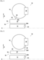
- FIG. 1 represents a partial schematic view in axial section of a turbomachine 10 according to a first embodiment.
- the turbomachine 10 comprises an axis of rotation A and a radial direction R.
- the turbomachine 10 comprises a first component 12 and a second component 14.
- the first component 12 is a turbopump body, for example a turbopump body hub
- the second component 14 is a turbopump turbine gas intake duct.
- the second component 14 is fixed to the first component 12 by an annular fixing flange 16.
- the annular fixing flange 16 is arranged radially between the first component 12 and the second component 14. As can be seen in the figure 1 , thanks to the annular fixing flange 16, the first component 12 and the second component 14 are fixed to each other without a triple flange arranged radially outside the second component, as is the case in turbomachines of the state of the art.
- the first component 12 is at a maximum temperature T1 and the second component is at a maximum temperature T2, the temperature T1 being lower than the temperature T2.
- the annular fixing flange 16 comprises, in sectional view along a plane comprising the axis of rotation A, an intermediate portion in the general shape of a “U” comprising a core 18 extended by two wings 20, 22, a first end 24 connected to the first component 12 and a second end 26 connected to the second component 14.
- each wing 20, 22 is extended by a fixing part 20A, 22A, each fixing part 20A, 22A carrying an end 24, 26.
- the turbomachine 10 also comprises turbine blades 28 supplied with hot gas by the second component 14, in particular the turbopump turbine gas intake duct.
- the annular fixing flange 16 is configured such that a maximum radial displacement per unit force of the second end is greater than or equal to 10 -9 mm/N (millimeter per Newton) and less than or equal to 10 -4 mm/N.
- the maximum flexibility of the annular fixing flange 16 is equal to approximately 1.7.10 -5 mm/N and for a minimum displacement of 1 mm of the second end 26 of the annular fixing flange 16 and a maximum force of approximately 280,933,781 N, the minimum flexibility of the annular fixing flange 16 is equal to 3.6.10 -9 mm/N.
- the maximum radial displacement per unit of force of the second end 26 of the annular fixing flange 16 is therefore between these two values of the flexibility of the annular fixing flange.
- the annular fixing flange can be made from INCONEL 718.
- FIG. 2 represents a second embodiment of the turbomachine 10 in which the second end 26 is arranged differently from the positioning of the first embodiment.
- the second end 26 can be positioned at different points of the second element 14.
- the first end 24 can also be arranged at different points, depending in particular on the size and therefore the space available in the turbomachine.
- FIG 3 represents a schematic view in axial section of the annular fixing flange of the figure 2 .
- the core 18 of the annular fixing flange 16 has a thickness E18 and a width L18 and the wings 20, 22 have a thickness E20, E22.
- the thickness E18 and the width L18 of the core 18 is greater than the thickness E20, E22 of the wings 20, 22.
- the thickness E20, E22 of the wings 20, 22 may be equal to 4 mm
- the thickness E18 of the core 18 may be equal to 10 mm
- the width L18 of the core 18 may be equal to 18 mm.
- the wings 20, 22 have thicknesses E20, E22 which are equal.
- the thicknesses E20, E22 could be different.
- the internal face has a non-zero radius of curvature R18.
- the radius of curvature R18 of the core 18 may be 4 mm (millimeter).
- the radius of curvature R18 of the core 18 is constant. It might not be constant.
- the fixing part 20A comprises a fixing hole 24B of the annular fixing flange 16 on the first component 12.
- the annular fixing flange 16 may be produced by additive manufacturing, for example by additive manufacturing by laser fusion on a powder bed.
- additive manufacturing When the annular fixing flange 16 is produced by additive manufacturing, it may be produced in a single piece with the second component. Thus, it is possible to dispense with means for fixing the second end 26 of the annular fixing flange 16 with the second component 14.
Landscapes
- Engineering & Computer Science (AREA)
- Chemical & Material Sciences (AREA)
- Combustion & Propulsion (AREA)
- Mechanical Engineering (AREA)
- General Engineering & Computer Science (AREA)
- Structures Of Non-Positive Displacement Pumps (AREA)
Claims (9)
- Turbomaschine (10), die eine Rotationsachse (A) und einen ringförmigen Befestigungsflansch (16) einer ersten Komponente (12) an eine zweite Komponente (14) umfasst, wobei die erste Komponente (12) ein Turbopumpenkörper ist und die zweite Komponente (14) ein Kanal zur Aufnahme von Gas der Turbopumpenturbine ist, wobei der ringförmige Befestigungsflansch (16), gesehen in Schnittansicht gemäß einer Ebene, die die Rotationsachse (A) umfasst, einen Zwischenabschnitt mit der allgemeinen Form eines "U", umfassend ein Zentralelement (18), das durch zwei Flügel (20, 22) verlängert ist, ein erstes Ende (24), das mit der ersten Komponente (12) verbunden ist, und ein zweites Ende (26), das mit der zweiten Komponente (14) verbunden ist, umfasst, wobei die erste Komponente (12) ausgelegt ist, um eine erste Temperatur (T1) aufzuweisen, und die zweite Komponente (14) ausgelegt ist, um eine zweite Temperatur (T2) aufzuweisen, wobei die zweite Temperatur (T2) höher als die erste Temperatur (T1) ist, wobei der ringförmige Befestigungsflansch (16) so konfiguriert ist, dass eine maximale radiale Verschiebung pro Krafteinheit des zweiten Endes (26) größer als oder gleich wie 10-9 mm/N und kleiner als oder gleich wie 10-4 mm/N ist.
- Turbomaschine (10) nach Anspruch 1, wobei der ringförmige Befestigungsflansch (16) so konfiguriert ist, dass die maximalen Belastungen aufgrund des thermischen Gradienten an jedem Punkt des ringförmigen Befestigungsflansches (16) im Bereich zwischen 100 MPa und 1000 MPa liegen.
- Turbomaschine (10) nach Anspruch 1 oder 2, wobei die erste Temperatur (T1) niedriger als oder gleich wie 200 K ist, vorzugsweise niedriger als oder gleich wie 150 K, noch bevorzugter niedriger als oder gleich wie 100 K, und die zweite Temperatur (T2) höher als oder gleich wie 300 K ist, vorzugsweise höher als oder gleich wie 500 K, noch bevorzugter höher als oder gleich wie 700 K.
- Turbomaschine (10) nach einem der Ansprüche 1 bis 3, wobei eine Länge des ringförmigen Befestigungsflansches (16), gemessen zwischen dem ersten Ende (24) und dem zweiten Ende (26), größer als oder gleich wie 20 Mal die maximale thermische Ausdehnung des ringförmigen Befestigungsflansches (16) ist, vorzugsweise größer als oder gleich wie 100 Mal, noch bevorzugter größer als oder gleich wie 500 Mal und kleiner als oder gleich wie 5000 Mal die maximale thermische Ausdehnung des ringförmigen Befestigungsflansches (16) ist, vorzugsweise kleiner als oder gleich wie 3000 Mal, noch bevorzugter kleiner als oder gleich wie 1000 Mal.
- Turbomaschine (10) nach Anspruch 4, wobei die zwei Flügel (20, 22) voneinander um einen Zwischenraum beabstandet sind, der größer als oder gleich wie 2 % der Länge des ringförmigen Befestigungsflansches ist, vorzugsweise größer als oder gleich wie 5 %, noch bevorzugter größer als oder gleich wie 10 % und kleiner als oder gleich wie 50 % der Länge des ringförmigen Befestigungsflansches.
- Turbomaschine (10) nach einem der Ansprüche 1 bis 5, wobei das Zentralelement (18) eine Dicke (E18) aufweist und die Flügel (20, 22) eine Dicke (E20, E22) aufweisen, wobei die Dicke (E18) des Zentralelements (18) größer als die Dicke (E20, E22) der Flügel (20, 22) ist, wobei vorzugsweise die Dicke (E18) des Zentralelements (18) 25 Mal größer als oder gleich wie die Dicke (E20, E22) der Flügel (20, 22) ist, noch bevorzugter 50 Mal größer als oder gleich wie die Dicke (E20, E22) der Flügel (20, 22) ist, noch bevorzugter 100 Mal größer als oder gleich wie die Dicke (E20, E22) der Flügel (20, 22) ist.
- Turbomaschine (10) nach einem der Ansprüche 1 bis 6, wobei das Zentralelement (18) eine Breite (L18) aufweist und die Flügel (20, 22) eine Dicke (E20, E22) aufweisen, wobei die Breite (L18) des Zentralelements (18) größer als die Dicke (E20, E22) der Flügel (20, 22) ist, wobei vorzugsweise die Breite (L18) des Zentralelements (18) 25 Mal größer als oder gleich wie die Dicke (E20, E22) der Flügel (20, 22) ist, noch bevorzugter 50 Mal größer als oder gleich wie die Dicke (E20, E22) der Flügel (20, 22) ist, noch bevorzugter 100 Mal größer als oder gleich wie die Dicke (E20, E22) der Flügel (20, 22) ist,
- Turbomaschine (10) nach einem der Ansprüche 1 bis 7, wobei das Zentralelement (18) eine Innenfläche aufweist, die einen Krümmungsradius (R18) von nicht null aufweist.
- Turbomaschine (10) nach einem der Ansprüche 1 bis 8, wobei der ringförmige Befestigungsflansch (16) aus Superlegierung hergestellt ist.
Applications Claiming Priority (1)
| Application Number | Priority Date | Filing Date | Title |
|---|---|---|---|
| FR1905256A FR3096411B1 (fr) | 2019-05-20 | 2019-05-20 | Turbomachine comprenant une bride annulaire de fixation |
Publications (3)
| Publication Number | Publication Date |
|---|---|
| EP3741965A1 EP3741965A1 (de) | 2020-11-25 |
| EP3741965B1 true EP3741965B1 (de) | 2024-10-16 |
| EP3741965C0 EP3741965C0 (de) | 2024-10-16 |
Family
ID=67587875
Family Applications (1)
| Application Number | Title | Priority Date | Filing Date |
|---|---|---|---|
| EP20175251.6A Active EP3741965B1 (de) | 2019-05-20 | 2020-05-18 | Turbomaschine, die einen ringförmigen befestigungsflansch umfasst |
Country Status (3)
| Country | Link |
|---|---|
| EP (1) | EP3741965B1 (de) |
| ES (1) | ES2998441T3 (de) |
| FR (1) | FR3096411B1 (de) |
Family Cites Families (3)
| Publication number | Priority date | Publication date | Assignee | Title |
|---|---|---|---|---|
| US3173250A (en) * | 1960-05-05 | 1965-03-16 | North American Aviation Inc | Reverse flow thrust chamber |
| US4126405A (en) * | 1976-12-16 | 1978-11-21 | General Electric Company | Turbine nozzle |
| FR2965319B1 (fr) * | 2010-09-27 | 2013-03-01 | Eurocopter France | Moyen d'accouplement flexible |
-
2019
- 2019-05-20 FR FR1905256A patent/FR3096411B1/fr active Active
-
2020
- 2020-05-18 ES ES20175251T patent/ES2998441T3/es active Active
- 2020-05-18 EP EP20175251.6A patent/EP3741965B1/de active Active
Also Published As
| Publication number | Publication date |
|---|---|
| EP3741965C0 (de) | 2024-10-16 |
| FR3096411B1 (fr) | 2021-06-11 |
| FR3096411A1 (fr) | 2020-11-27 |
| EP3741965A1 (de) | 2020-11-25 |
| ES2998441T3 (en) | 2025-02-20 |
Similar Documents
| Publication | Publication Date | Title |
|---|---|---|
| EP1970537B1 (de) | Gebläse eines Turbotriebwerks | |
| EP1847686B1 (de) | Vorrichtung zur Befestigung von Ringsektoren an einem Turbinengehäuse einer Strömungsmaschine | |
| EP2053200B1 (de) | Regelung des Blattspitzenspiels der Hochdruckturbine eines Turbinentriebwerks | |
| EP1455055B1 (de) | Turbomachine mit gekühlten Mantelringsegmenten | |
| CA2400151C (fr) | Secteur d'entretoise de support d'anneau de stator de la turbine haute pression d'une turbomachine avec rattrapage de jeux | |
| EP1265031B1 (de) | Befestigung von metallischen Aufsätzen auf CMC-Turbomaschinenbrennkammerwänden | |
| CA2870102C (fr) | Etage de turbine pour une turbomachine | |
| FR2643416A1 (fr) | Carter pour machine tournante, notamment pour un turbomoteur, et son procede d'assemblage | |
| EP3781793B1 (de) | Keramischer leitschaufelring zum kraftaufnahme | |
| WO2019202249A2 (fr) | Distributeur en cmc avec reprise d'effort par une pince étanche | |
| WO2010072968A1 (fr) | Roue mobile de turbomachine a aubes en materiau composite munie d'un anneau ressort | |
| FR2980235A1 (fr) | Anneau pour une turbine de turbomachine | |
| CA2518355A1 (fr) | Retenue des clavettes de centrage des anneaux sous aubes de stator a calage variable d'un moteur a turbine a gaz | |
| FR3020408A1 (fr) | Ensemble rotatif pour turbomachine | |
| EP3074611A1 (de) | Vorrichtung zur zentrierung und führung der rotation einer turbinenmotorwelle mit verbessertem mittel zum zurückhalten des äusseren lagerrings | |
| EP2060751A1 (de) | Turbinen- oder Kompressorstufe eines Turbotriebwerks | |
| EP3741965B1 (de) | Turbomaschine, die einen ringförmigen befestigungsflansch umfasst | |
| FR2961848A1 (fr) | Etage de turbine | |
| WO2023131759A1 (fr) | Turbine pour turbomachine | |
| CA2644312C (fr) | Etage de turbine ou de compresseur de turbomachine | |
| EP3983725B1 (de) | Anordnung für eine gasturbine | |
| EP3857031B1 (de) | Ringvorrichtung für turbomaschine und verfahren zum einbau einer solchen vorrichtung | |
| FR3024884B1 (fr) | Procede de realisation d'un anneau sectorise d'etancheite et d'une turbine de turbomachine | |
| FR3141207A1 (fr) | Anneau d’étanchéité pour turbine démontable par l’amont | |
| FR3052486A1 (fr) | Secteur de distributeur pour turbomachine comprenant une plateforme separees en portions circonferentielles |
Legal Events
| Date | Code | Title | Description |
|---|---|---|---|
| PUAI | Public reference made under article 153(3) epc to a published international application that has entered the european phase |
Free format text: ORIGINAL CODE: 0009012 |
|
| STAA | Information on the status of an ep patent application or granted ep patent |
Free format text: STATUS: THE APPLICATION HAS BEEN PUBLISHED |
|
| AK | Designated contracting states |
Kind code of ref document: A1 Designated state(s): AL AT BE BG CH CY CZ DE DK EE ES FI FR GB GR HR HU IE IS IT LI LT LU LV MC MK MT NL NO PL PT RO RS SE SI SK SM TR |
|
| AX | Request for extension of the european patent |
Extension state: BA ME |
|
| STAA | Information on the status of an ep patent application or granted ep patent |
Free format text: STATUS: REQUEST FOR EXAMINATION WAS MADE |
|
| 17P | Request for examination filed |
Effective date: 20210521 |
|
| RBV | Designated contracting states (corrected) |
Designated state(s): AL AT BE BG CH CY CZ DE DK EE ES FI FR GB GR HR HU IE IS IT LI LT LU LV MC MK MT NL NO PL PT RO RS SE SI SK SM TR |
|
| RAP3 | Party data changed (applicant data changed or rights of an application transferred) |
Owner name: ARIANEGROUP SAS |
|
| STAA | Information on the status of an ep patent application or granted ep patent |
Free format text: STATUS: EXAMINATION IS IN PROGRESS |
|
| 17Q | First examination report despatched |
Effective date: 20220614 |
|
| P01 | Opt-out of the competence of the unified patent court (upc) registered |
Effective date: 20230612 |
|
| GRAP | Despatch of communication of intention to grant a patent |
Free format text: ORIGINAL CODE: EPIDOSNIGR1 |
|
| STAA | Information on the status of an ep patent application or granted ep patent |
Free format text: STATUS: GRANT OF PATENT IS INTENDED |
|
| INTG | Intention to grant announced |
Effective date: 20231222 |
|
| GRAJ | Information related to disapproval of communication of intention to grant by the applicant or resumption of examination proceedings by the epo deleted |
Free format text: ORIGINAL CODE: EPIDOSDIGR1 |
|
| STAA | Information on the status of an ep patent application or granted ep patent |
Free format text: STATUS: EXAMINATION IS IN PROGRESS |
|
| INTC | Intention to grant announced (deleted) | ||
| GRAS | Grant fee paid |
Free format text: ORIGINAL CODE: EPIDOSNIGR3 |
|
| STAA | Information on the status of an ep patent application or granted ep patent |
Free format text: STATUS: GRANT OF PATENT IS INTENDED |
|
| GRAP | Despatch of communication of intention to grant a patent |
Free format text: ORIGINAL CODE: EPIDOSNIGR1 |
|
| INTG | Intention to grant announced |
Effective date: 20240618 |
|
| GRAA | (expected) grant |
Free format text: ORIGINAL CODE: 0009210 |
|
| STAA | Information on the status of an ep patent application or granted ep patent |
Free format text: STATUS: THE PATENT HAS BEEN GRANTED |
|
| AK | Designated contracting states |
Kind code of ref document: B1 Designated state(s): AL AT BE BG CH CY CZ DE DK EE ES FI FR GB GR HR HU IE IS IT LI LT LU LV MC MK MT NL NO PL PT RO RS SE SI SK SM TR |
|
| REG | Reference to a national code |
Ref country code: GB Ref legal event code: FG4D Free format text: NOT ENGLISH |
|
| REG | Reference to a national code |
Ref country code: DE Ref legal event code: R096 Ref document number: 602020039430 Country of ref document: DE Ref country code: CH Ref legal event code: EP |
|
| REG | Reference to a national code |
Ref country code: IE Ref legal event code: FG4D Free format text: LANGUAGE OF EP DOCUMENT: FRENCH |
|
| U01 | Request for unitary effect filed |
Effective date: 20241108 |
|
| U07 | Unitary effect registered |
Designated state(s): AT BE BG DE DK EE FI FR IT LT LU LV MT NL PT RO SE SI Effective date: 20241119 |
|
| P04 | Withdrawal of opt-out of the competence of the unified patent court (upc) registered |
Free format text: CASE NUMBER: APP_61237/2024 Effective date: 20241115 |
|
| REG | Reference to a national code |
Ref country code: ES Ref legal event code: FG2A Ref document number: 2998441 Country of ref document: ES Kind code of ref document: T3 Effective date: 20250220 |
|
| PG25 | Lapsed in a contracting state [announced via postgrant information from national office to epo] |
Ref country code: IS Free format text: LAPSE BECAUSE OF FAILURE TO SUBMIT A TRANSLATION OF THE DESCRIPTION OR TO PAY THE FEE WITHIN THE PRESCRIBED TIME-LIMIT Effective date: 20250216 Ref country code: HR Free format text: LAPSE BECAUSE OF FAILURE TO SUBMIT A TRANSLATION OF THE DESCRIPTION OR TO PAY THE FEE WITHIN THE PRESCRIBED TIME-LIMIT Effective date: 20241016 |
|
| PG25 | Lapsed in a contracting state [announced via postgrant information from national office to epo] |
Ref country code: NO Free format text: LAPSE BECAUSE OF FAILURE TO SUBMIT A TRANSLATION OF THE DESCRIPTION OR TO PAY THE FEE WITHIN THE PRESCRIBED TIME-LIMIT Effective date: 20250116 |
|
| PG25 | Lapsed in a contracting state [announced via postgrant information from national office to epo] |
Ref country code: GR Free format text: LAPSE BECAUSE OF FAILURE TO SUBMIT A TRANSLATION OF THE DESCRIPTION OR TO PAY THE FEE WITHIN THE PRESCRIBED TIME-LIMIT Effective date: 20250117 |
|
| PG25 | Lapsed in a contracting state [announced via postgrant information from national office to epo] |
Ref country code: PL Free format text: LAPSE BECAUSE OF FAILURE TO SUBMIT A TRANSLATION OF THE DESCRIPTION OR TO PAY THE FEE WITHIN THE PRESCRIBED TIME-LIMIT Effective date: 20241016 |
|
| PG25 | Lapsed in a contracting state [announced via postgrant information from national office to epo] |
Ref country code: RS Free format text: LAPSE BECAUSE OF FAILURE TO SUBMIT A TRANSLATION OF THE DESCRIPTION OR TO PAY THE FEE WITHIN THE PRESCRIBED TIME-LIMIT Effective date: 20250116 |
|
| U20 | Renewal fee for the european patent with unitary effect paid |
Year of fee payment: 6 Effective date: 20250528 |
|
| PG25 | Lapsed in a contracting state [announced via postgrant information from national office to epo] |
Ref country code: SM Free format text: LAPSE BECAUSE OF FAILURE TO SUBMIT A TRANSLATION OF THE DESCRIPTION OR TO PAY THE FEE WITHIN THE PRESCRIBED TIME-LIMIT Effective date: 20241016 |
|
| PGFP | Annual fee paid to national office [announced via postgrant information from national office to epo] |
Ref country code: CH Payment date: 20250601 Year of fee payment: 6 |
|
| PG25 | Lapsed in a contracting state [announced via postgrant information from national office to epo] |
Ref country code: SK Free format text: LAPSE BECAUSE OF FAILURE TO SUBMIT A TRANSLATION OF THE DESCRIPTION OR TO PAY THE FEE WITHIN THE PRESCRIBED TIME-LIMIT Effective date: 20241016 |
|
| PG25 | Lapsed in a contracting state [announced via postgrant information from national office to epo] |
Ref country code: CZ Free format text: LAPSE BECAUSE OF FAILURE TO SUBMIT A TRANSLATION OF THE DESCRIPTION OR TO PAY THE FEE WITHIN THE PRESCRIBED TIME-LIMIT Effective date: 20241016 |
|
| PLBE | No opposition filed within time limit |
Free format text: ORIGINAL CODE: 0009261 |
|
| STAA | Information on the status of an ep patent application or granted ep patent |
Free format text: STATUS: NO OPPOSITION FILED WITHIN TIME LIMIT |
|
| 26N | No opposition filed |
Effective date: 20250717 |
|
| PGFP | Annual fee paid to national office [announced via postgrant information from national office to epo] |
Ref country code: ES Payment date: 20250630 Year of fee payment: 6 |
|
| PG25 | Lapsed in a contracting state [announced via postgrant information from national office to epo] |
Ref country code: MC Free format text: LAPSE BECAUSE OF FAILURE TO SUBMIT A TRANSLATION OF THE DESCRIPTION OR TO PAY THE FEE WITHIN THE PRESCRIBED TIME-LIMIT Effective date: 20241016 |
|
| PGFP | Annual fee paid to national office [announced via postgrant information from national office to epo] |
Ref country code: GB Payment date: 20260306 Year of fee payment: 7 |
|
| PG25 | Lapsed in a contracting state [announced via postgrant information from national office to epo] |
Ref country code: IE Free format text: LAPSE BECAUSE OF NON-PAYMENT OF DUE FEES Effective date: 20250518 |