EP3741965A1 - Turbomaschine, die einen ringförmigen befestigungsflansch umfasst - Google Patents
Turbomaschine, die einen ringförmigen befestigungsflansch umfasst Download PDFInfo
- Publication number
- EP3741965A1 EP3741965A1 EP20175251.6A EP20175251A EP3741965A1 EP 3741965 A1 EP3741965 A1 EP 3741965A1 EP 20175251 A EP20175251 A EP 20175251A EP 3741965 A1 EP3741965 A1 EP 3741965A1
- Authority
- EP
- European Patent Office
- Prior art keywords
- equal
- component
- turbomachine
- thickness
- annular fixing
- Prior art date
- Legal status (The legal status is an assumption and is not a legal conclusion. Google has not performed a legal analysis and makes no representation as to the accuracy of the status listed.)
- Granted
Links
Images
Classifications
-
- F—MECHANICAL ENGINEERING; LIGHTING; HEATING; WEAPONS; BLASTING
- F01—MACHINES OR ENGINES IN GENERAL; ENGINE PLANTS IN GENERAL; STEAM ENGINES
- F01D—NON-POSITIVE DISPLACEMENT MACHINES OR ENGINES, e.g. STEAM TURBINES
- F01D25/00—Component parts, details, or accessories, not provided for in, or of interest apart from, other groups
- F01D25/24—Casings; Casing parts, e.g. diaphragms, casing fastenings
- F01D25/243—Flange connections; Bolting arrangements
-
- F—MECHANICAL ENGINEERING; LIGHTING; HEATING; WEAPONS; BLASTING
- F02—COMBUSTION ENGINES; HOT-GAS OR COMBUSTION-PRODUCT ENGINE PLANTS
- F02C—GAS-TURBINE PLANTS; AIR INTAKES FOR JET-PROPULSION PLANTS; CONTROLLING FUEL SUPPLY IN AIR-BREATHING JET-PROPULSION PLANTS
- F02C7/00—Features, components parts, details or accessories, not provided for in, or of interest apart form groups F02C1/00 - F02C6/00; Air intakes for jet-propulsion plants
- F02C7/20—Mounting or supporting of plant; Accommodating heat expansion or creep
-
- F—MECHANICAL ENGINEERING; LIGHTING; HEATING; WEAPONS; BLASTING
- F02—COMBUSTION ENGINES; HOT-GAS OR COMBUSTION-PRODUCT ENGINE PLANTS
- F02K—JET-PROPULSION PLANTS
- F02K9/00—Rocket-engine plants, i.e. plants carrying both fuel and oxidant therefor; Control thereof
- F02K9/42—Rocket-engine plants, i.e. plants carrying both fuel and oxidant therefor; Control thereof using liquid or gaseous propellants
- F02K9/44—Feeding propellants
- F02K9/46—Feeding propellants using pumps
-
- F—MECHANICAL ENGINEERING; LIGHTING; HEATING; WEAPONS; BLASTING
- F02—COMBUSTION ENGINES; HOT-GAS OR COMBUSTION-PRODUCT ENGINE PLANTS
- F02K—JET-PROPULSION PLANTS
- F02K9/00—Rocket-engine plants, i.e. plants carrying both fuel and oxidant therefor; Control thereof
- F02K9/42—Rocket-engine plants, i.e. plants carrying both fuel and oxidant therefor; Control thereof using liquid or gaseous propellants
- F02K9/60—Constructional parts; Details not otherwise provided for
-
- F—MECHANICAL ENGINEERING; LIGHTING; HEATING; WEAPONS; BLASTING
- F05—INDEXING SCHEMES RELATING TO ENGINES OR PUMPS IN VARIOUS SUBCLASSES OF CLASSES F01-F04
- F05D—INDEXING SCHEME FOR ASPECTS RELATING TO NON-POSITIVE-DISPLACEMENT MACHINES OR ENGINES, GAS-TURBINES OR JET-PROPULSION PLANTS
- F05D2250/00—Geometry
- F05D2250/70—Shape
- F05D2250/75—Shape given by its similarity to a letter, e.g. T-shaped
Definitions
- the present disclosure relates to a turbomachine comprising an annular fixing flange.
- Turbomachines comprising a turbopump.
- the turbopump is composed of a generally cold pump and a turbine, generally activated by hot gases.
- the integration of the whole of the turbomachine requires controlling the passage of forces between the pump and the turbine while controlling the changes in dimension due to the temperature difference between the pump and the turbine.
- the turbine housing is connected to the rest of the turbomachine, generally to the central hub of the turbomachine, by an annular fixing flange positioned under the inlet torus of the turbine.
- turbomachines that is to say in which the pressure levels are generally greater than 100 bars and the thermal gradients greater than 450 K between the pump and the turbine, the temperature difference between the pump and the turbine create relatively high mechanical stresses when the turbine, and in particular the inlet torus of the turbine, is connected to the central hub of the turbomachine by an annular fixing flange positioned under the inlet torus of the turbine.
- the turbine in particular the turbine casing, is connected to the rest of the turbomachine by an annular fixing flange arranged above the inlet torus of the turbine and of which one end is connected to the turbine and one end is connected to an outer casing of the pump of the turbomachine.
- the annular fixing flange is connected to two other flanges and forms a triple flange which makes the design and assembly of the turbomachine, in particular of the turbine, more complex than in the case of a so-called “low power” turbomachine.
- heat shields In addition, in order to limit the thermal gradients between the pump and the turbine, heat shields, generally at least two, are installed between the pump and the turbine, in particular around the inlet toroid of the turbine, and an element d The seal is installed in order to prevent hot gases flowing in the turbine from returning to cooler parts of the turbomachine, in particular the pump.
- These heat shields and this sealing element make the design, manufacture and assembly of the turbomachine more complex than in the case of a so-called “low power” turbomachine. This complexity also leads to higher manufacturing costs for the turbomachine than in the case of a so-called “low power” turbomachine.
- the present disclosure aims to remedy at least in part these drawbacks.
- the present disclosure relates to a turbomachine comprising an axis of rotation and an annular flange for fixing a first component to a second component, the annular flange for fixing comprising, in sectional view along a plane comprising the axis of rotation, an intermediate portion in the general shape of a "U" comprising a core extended by two wings, a first end connected to the first component and a second end connected to the second component, the first component being intended to be at a first temperature and the second component being intended to be at a second temperature, the second temperature being higher than the first temperature, the annular fixing flange being configured so that a maximum radial displacement per unit force of the second end is greater than or equal to 10 -9 mm / N (millimeter per Newton) and less than or equal to 10 -4 mm / N.
- the section plane comprising the axis of rotation of the turbomachine is an axial section plane.
- the annular fixing flange is positioned radially between the first and the second component, that is to say that the first and the second end of the annular flange of fasteners are disposed radially between the first component and an outer radial end of the second component.
- the annular fixing flange is not a flange radially external to the second component.
- each wing has one of the ends of the annular fixing flange.
- first temperature and the second temperature are maximum temperatures in operation of the turbomachine.
- the positioning of the annular fixing flange between the first and the second component also makes it possible to dispense with the triple flange and to reduce the mass of the annular fixing flange.
- the annular fixing flange when the annular fixing flange is connected to an outer casing, the annular fixing flange has a greater mass than when the annular fixing flange is positioned between the first and the second component.
- annular fixing flange can also act as a seal between the first and the second component and prevent hot gases flowing through the second component from returning to the first component. This makes it possible to reduce the number of components, the mass of the components required for mounting the second component in the turbomachine and to reduce the complexity of the design and mounting of the second component in the turbomachine.
- the operating radial displacement of the second component is controlled and the annular fixing flange while having a certain elasticity has a rigidity allowing the first component to be fixed to the second component and this, between the operating temperature (holding factor of safety) and the ambient temperature, while taking into account the different temperatures of the components in operation.
- the safety coefficient for the temperature may for example be 20%.
- the minimum temperature will be reduced by 20% and the maximum temperature will be increased by 20%.
- the radial displacement per unit force reflects the flexibility of the annular mounting flange.
- the maximum flexibility of the annular fixing flange will be obtained by the ratio of a maximum displacement of the second end of the annular fixing flange compared to the minimum force and the minimum flexibility of the annular fixing flange will be obtained by the ratio of a minimum displacement of the second end of the annular fixing flange to the maximum force.
- the maximum radial displacement per unit of force of the second end of the annular fixing flange is therefore between these two values of the flexibility of the annular fixing flange.
- the annular fixing flange therefore makes it possible to fix the first component called “cold” to the second component called “hot”.
- the annular fixing flange is configured so that the maximum stresses due to the thermal gradient at any point of the annular fixing flange are between 100 MPa (megapascal) and 1000 MPa.
- the safety coefficient for the temperature may for example be 20%.
- the minimum temperature will be reduced by 20% and the maximum temperature will be increased by 20%.
- the first temperature is less than or equal to 200 K, preferably less than or equal to 150 K, even more preferably less than or equal to 100 K and the second temperature is greater than or equal to 300 K, preferably greater than or equal to 500 K, even more preferably greater than or equal to 700 K.
- a length of the annular securing flange, measured between the first end and the second end is greater than or equal to 20 times the maximum thermal expansion of the annular securing flange, preferably greater than or equal to 100 times, even more preferably greater than or equal to 500 times and less than or equal to 5000 times the maximum thermal expansion of the annular fixing flange, preferably less than or equal to 3000 times, even more preferably less than or equal to 1000 times.
- the maximum thermal expansion is determined between room temperature and operating temperatures, i.e. the first temperature and the second temperature, and is compared to the length of the ring clamp at room temperature.
- the two wings are spaced apart from each other by a space greater than or equal to 2% of the length of the annular fixing flange, preferably greater than or equal to 5%, even more than preferably greater than or equal to 10% and less than or equal to 50% of the length of the annular fixing flange.
- the core has a thickness and the wings have a thickness, the thickness of the core being greater than the thickness of the wings, preferably the thickness of the core being 25 times greater than or equal. the thickness of the wings, even more preferably 50 times greater than or equal to the thickness of the wings, even more preferably 100 times greater than or equal to the thickness of the wings.
- the core has a width and the wings have a thickness, the width of the core being greater than the thickness of the wings, preferably the width of the core being 25 times greater than or equal to 'wing thickness, even more preferably 50 times greater or equal to the thickness of the wings, even more preferably 100 times greater than or equal to the thickness of the wings.
- the core has an internal face having a non-zero radius of curvature.
- the upper limit of the radius of curvature of the core of the annular fixing flange is generally given by the space available between the annular fixing flange and the second component.
- the radius of curvature may not be constant, that is, it may vary.
- the internal face could have two curved portions separated from one another by a straight portion.
- the first component is a turbopump body, eg, a turbopump body hub
- the second component is a turbopump turbine gas inlet duct.
- the annular fixing flange is made of a superalloy.
- superalloys based on nickel-chromium such as the alloys commonly designated by the registered trademark Inconel®, Hastelloy® X, superalloys based on nickel-copper, such as the alloys commonly designated by the Monel® trademark, nickel-chromium-cobalt-based superalloys, such as the alloys commonly designated by the registered trademark Waspalloy®, Nimonic®, Astroloy®, martensitic stainless steel superalloys, such as the alloys commonly designated by the registered trademark 17-7-PH®.
- the annular fixing flange and the second component form a single piece.
- the assembly of the turbomachine is simplified.
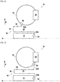
- the figure 1 represents a partial schematic view in axial section of a turbomachine 10 according to a first embodiment.
- the turbomachine 10 comprises an axis of rotation A and a radial direction R.
- the turbomachine 10 comprises a first component 12 and a second component 14.
- the first component 12 is a turbopump body, for example a turbopump body hub
- the second component 14 is a turbopump turbine gas inlet duct.
- the second component 14 is fixed to the first component 12 by an annular fixing flange 16.
- the annular fixing flange 16 is disposed radially between the first component 12 and the second component 14. As can be seen in the figure. figure 1 , thanks to the annular fixing flange 16, the first component 12 and the second component 14 are fixed to each other without a triple flange disposed radially outside the second component, as is the case in turbomachines of the state of the art.
- the first component 12 is at a maximum temperature T1 and the second component is at a maximum temperature T2, the temperature T1 being lower than the temperature T2.
- the annular fixing flange 16 comprises, in sectional view along a plane comprising the axis of rotation A, an intermediate portion in the general shape of a "U" comprising a core 18 extended by two wings 20, 22, a first end 24 connected to the first component 12 and a second end 26 connected to the second component 14.
- each wing 20, 22 is extended by a fixing part 20A, 22A, each fixing part 20A, 22A carrying an end 24, 26.
- the turbomachine 10 also comprises turbine blades 28 supplied with hot gas by the second component 14, in this example the turbopump turbine gas inlet duct.
- the annular fixing flange 16 is configured so that a maximum radial displacement per unit force of the second end is greater than or equal to 10 -9 mm / N (millimeter per Newton) and less than or equal to 10 -4 mm / N .
- the maximum flexibility of the annular fixing flange 16 is equal to approximately 1.7.10 -5 mm / N and for a minimum displacement of 1 mm of the second end 26 of the annular fixing flange 16 and a maximum force of approximately 280 933 781 N, the minimum flexibility of the annular flange fixing 16 is equal to 3.6.10 -9 mm / N.
- the maximum radial displacement per unit of force of the second end 26 of the annular fixing flange 16 is therefore between these two values of the flexibility of the annular fixing flange.
- the annular fixing flange can be made from INCONEL 718.
- the figure 2 shows a second embodiment of the turbomachine 10 in which the second end 26 is arranged differently from the positioning of the first embodiment.
- the second end 26 can be positioned at different points from the second element 14.
- the first end 24 can also be arranged at different points, depending in particular on the size and therefore on the space available in the turbomachine.
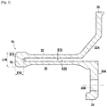
- the figure 3 shows a schematic view in axial section of the annular flange for fixing the figure 2 .
- the core 18 of the annular fixing flange 16 has a thickness E18 and a width L18 and the flanges 20, 22 have a thickness E20, E22.
- the thickness E18 and the width L18 of the core 18 is greater than the thickness E20, E22 of the wings 20, 22.
- the thickness E20, E22 of the wings 20, 22 can be equal to 4 mm
- the thickness E18 of the core 18 may be equal to 10 mm
- the width L18 of the core 18 may be equal to 18 mm.
- the wings 20, 22 have thicknesses E20, E22 which are equal.
- the thicknesses E20, E22 could be different.
- the internal face has a non-zero radius of curvature R18.
- the radius of curvature R18 of the core 18 can be 4 mm (millimeter).
- the radius of curvature R18 of the core 18 is constant. It might not be constant.
- the fixing part 20A has a fixing hole 24B of the annular fixing flange 16 on the first component 12.
- the annular fixing flange 16 can be produced by additive manufacturing, for example by additive manufacturing by laser fusion on a powder bed.
- additive manufacturing for example by additive manufacturing by laser fusion on a powder bed.
- the annular fixing flange 16 can be produced in one piece with the second component.
- it is possible to do without means of fixing the second end 26 of the annular fixing flange 16 with the second component 14.
Landscapes
- Engineering & Computer Science (AREA)
- Chemical & Material Sciences (AREA)
- Combustion & Propulsion (AREA)
- Mechanical Engineering (AREA)
- General Engineering & Computer Science (AREA)
- Structures Of Non-Positive Displacement Pumps (AREA)
Applications Claiming Priority (1)
| Application Number | Priority Date | Filing Date | Title |
|---|---|---|---|
| FR1905256A FR3096411B1 (fr) | 2019-05-20 | 2019-05-20 | Turbomachine comprenant une bride annulaire de fixation |
Publications (3)
| Publication Number | Publication Date |
|---|---|
| EP3741965A1 true EP3741965A1 (de) | 2020-11-25 |
| EP3741965B1 EP3741965B1 (de) | 2024-10-16 |
| EP3741965C0 EP3741965C0 (de) | 2024-10-16 |
Family
ID=67587875
Family Applications (1)
| Application Number | Title | Priority Date | Filing Date |
|---|---|---|---|
| EP20175251.6A Active EP3741965B1 (de) | 2019-05-20 | 2020-05-18 | Turbomaschine, die einen ringförmigen befestigungsflansch umfasst |
Country Status (3)
| Country | Link |
|---|---|
| EP (1) | EP3741965B1 (de) |
| ES (1) | ES2998441T3 (de) |
| FR (1) | FR3096411B1 (de) |
Citations (3)
| Publication number | Priority date | Publication date | Assignee | Title |
|---|---|---|---|---|
| US3173250A (en) * | 1960-05-05 | 1965-03-16 | North American Aviation Inc | Reverse flow thrust chamber |
| US4126405A (en) * | 1976-12-16 | 1978-11-21 | General Electric Company | Turbine nozzle |
| US20120077607A1 (en) * | 2010-09-27 | 2012-03-29 | Eurocopter | Flexible coupling means |
-
2019
- 2019-05-20 FR FR1905256A patent/FR3096411B1/fr active Active
-
2020
- 2020-05-18 ES ES20175251T patent/ES2998441T3/es active Active
- 2020-05-18 EP EP20175251.6A patent/EP3741965B1/de active Active
Patent Citations (3)
| Publication number | Priority date | Publication date | Assignee | Title |
|---|---|---|---|---|
| US3173250A (en) * | 1960-05-05 | 1965-03-16 | North American Aviation Inc | Reverse flow thrust chamber |
| US4126405A (en) * | 1976-12-16 | 1978-11-21 | General Electric Company | Turbine nozzle |
| US20120077607A1 (en) * | 2010-09-27 | 2012-03-29 | Eurocopter | Flexible coupling means |
Also Published As
| Publication number | Publication date |
|---|---|
| EP3741965B1 (de) | 2024-10-16 |
| EP3741965C0 (de) | 2024-10-16 |
| FR3096411B1 (fr) | 2021-06-11 |
| FR3096411A1 (fr) | 2020-11-27 |
| ES2998441T3 (en) | 2025-02-20 |
Similar Documents
| Publication | Publication Date | Title |
|---|---|---|
| EP1970537B1 (de) | Gebläse eines Turbotriebwerks | |
| EP1265031B1 (de) | Befestigung von metallischen Aufsätzen auf CMC-Turbomaschinenbrennkammerwänden | |
| EP1455055B1 (de) | Turbomachine mit gekühlten Mantelringsegmenten | |
| EP2053200B1 (de) | Regelung des Blattspitzenspiels der Hochdruckturbine eines Turbinentriebwerks | |
| EP3473806A1 (de) | Gehäuse für ein turbotriebwerk, das einen zentralen abschnitt umfasst, der relativ zu zwei seitenabschnitten im bereich einer verbindung hervorragt | |
| FR2643416A1 (fr) | Carter pour machine tournante, notamment pour un turbomoteur, et son procede d'assemblage | |
| EP1265034A1 (de) | Befestigung einer Turbinenbrennkammer aus keramischem Matrix-Verbundswerkstoff mit gelöteten Befestigungsfüssen | |
| EP1265032A1 (de) | Gasturbinenbrennkammer aus Verbundwerkstoff mit keramischer Matrix | |
| EP3781793B1 (de) | Keramischer leitschaufelring zum kraftaufnahme | |
| FR2980235A1 (fr) | Anneau pour une turbine de turbomachine | |
| WO2010072968A1 (fr) | Roue mobile de turbomachine a aubes en materiau composite munie d'un anneau ressort | |
| EP1265036A1 (de) | Elastische Befestigung einer Turbinenbrennkammer aus keramischem Matrix-Verbundwerkstoff in einem metallischen Gehäuse | |
| FR3020408A1 (fr) | Ensemble rotatif pour turbomachine | |
| EP3074611A1 (de) | Vorrichtung zur zentrierung und führung der rotation einer turbinenmotorwelle mit verbessertem mittel zum zurückhalten des äusseren lagerrings | |
| EP2060751A1 (de) | Turbinen- oder Kompressorstufe eines Turbotriebwerks | |
| EP3741965B1 (de) | Turbomaschine, die einen ringförmigen befestigungsflansch umfasst | |
| FR2961848A1 (fr) | Etage de turbine | |
| WO2023131759A1 (fr) | Turbine pour turbomachine | |
| CA2644312C (fr) | Etage de turbine ou de compresseur de turbomachine | |
| EP3983725B1 (de) | Anordnung für eine gasturbine | |
| EP3857031A1 (de) | Ringförmige anordnung für einen turbinenmotor | |
| FR3065481A1 (fr) | Ensemble pour turbine, notamment pour une turbomachine | |
| FR3024884B1 (fr) | Procede de realisation d'un anneau sectorise d'etancheite et d'une turbine de turbomachine | |
| FR3159629A1 (fr) | Dispositif de fixation amélioré pour distributeur de turbine de turbomachine | |
| FR3141207A1 (fr) | Anneau d’étanchéité pour turbine démontable par l’amont |
Legal Events
| Date | Code | Title | Description |
|---|---|---|---|
| PUAI | Public reference made under article 153(3) epc to a published international application that has entered the european phase |
Free format text: ORIGINAL CODE: 0009012 |
|
| STAA | Information on the status of an ep patent application or granted ep patent |
Free format text: STATUS: THE APPLICATION HAS BEEN PUBLISHED |
|
| AK | Designated contracting states |
Kind code of ref document: A1 Designated state(s): AL AT BE BG CH CY CZ DE DK EE ES FI FR GB GR HR HU IE IS IT LI LT LU LV MC MK MT NL NO PL PT RO RS SE SI SK SM TR |
|
| AX | Request for extension of the european patent |
Extension state: BA ME |
|
| STAA | Information on the status of an ep patent application or granted ep patent |
Free format text: STATUS: REQUEST FOR EXAMINATION WAS MADE |
|
| 17P | Request for examination filed |
Effective date: 20210521 |
|
| RBV | Designated contracting states (corrected) |
Designated state(s): AL AT BE BG CH CY CZ DE DK EE ES FI FR GB GR HR HU IE IS IT LI LT LU LV MC MK MT NL NO PL PT RO RS SE SI SK SM TR |
|
| RAP3 | Party data changed (applicant data changed or rights of an application transferred) |
Owner name: ARIANEGROUP SAS |
|
| STAA | Information on the status of an ep patent application or granted ep patent |
Free format text: STATUS: EXAMINATION IS IN PROGRESS |
|
| 17Q | First examination report despatched |
Effective date: 20220614 |
|
| P01 | Opt-out of the competence of the unified patent court (upc) registered |
Effective date: 20230612 |
|
| GRAP | Despatch of communication of intention to grant a patent |
Free format text: ORIGINAL CODE: EPIDOSNIGR1 |
|
| STAA | Information on the status of an ep patent application or granted ep patent |
Free format text: STATUS: GRANT OF PATENT IS INTENDED |
|
| INTG | Intention to grant announced |
Effective date: 20231222 |
|
| GRAJ | Information related to disapproval of communication of intention to grant by the applicant or resumption of examination proceedings by the epo deleted |
Free format text: ORIGINAL CODE: EPIDOSDIGR1 |
|
| STAA | Information on the status of an ep patent application or granted ep patent |
Free format text: STATUS: EXAMINATION IS IN PROGRESS |
|
| INTC | Intention to grant announced (deleted) | ||
| GRAS | Grant fee paid |
Free format text: ORIGINAL CODE: EPIDOSNIGR3 |
|
| STAA | Information on the status of an ep patent application or granted ep patent |
Free format text: STATUS: GRANT OF PATENT IS INTENDED |
|
| GRAP | Despatch of communication of intention to grant a patent |
Free format text: ORIGINAL CODE: EPIDOSNIGR1 |
|
| INTG | Intention to grant announced |
Effective date: 20240618 |
|
| GRAA | (expected) grant |
Free format text: ORIGINAL CODE: 0009210 |
|
| STAA | Information on the status of an ep patent application or granted ep patent |
Free format text: STATUS: THE PATENT HAS BEEN GRANTED |
|
| AK | Designated contracting states |
Kind code of ref document: B1 Designated state(s): AL AT BE BG CH CY CZ DE DK EE ES FI FR GB GR HR HU IE IS IT LI LT LU LV MC MK MT NL NO PL PT RO RS SE SI SK SM TR |
|
| REG | Reference to a national code |
Ref country code: GB Ref legal event code: FG4D Free format text: NOT ENGLISH |
|
| REG | Reference to a national code |
Ref country code: DE Ref legal event code: R096 Ref document number: 602020039430 Country of ref document: DE Ref country code: CH Ref legal event code: EP |
|
| REG | Reference to a national code |
Ref country code: IE Ref legal event code: FG4D Free format text: LANGUAGE OF EP DOCUMENT: FRENCH |
|
| U01 | Request for unitary effect filed |
Effective date: 20241108 |
|
| U07 | Unitary effect registered |
Designated state(s): AT BE BG DE DK EE FI FR IT LT LU LV MT NL PT RO SE SI Effective date: 20241119 |
|
| P04 | Withdrawal of opt-out of the competence of the unified patent court (upc) registered |
Free format text: CASE NUMBER: APP_61237/2024 Effective date: 20241115 |
|
| REG | Reference to a national code |
Ref country code: ES Ref legal event code: FG2A Ref document number: 2998441 Country of ref document: ES Kind code of ref document: T3 Effective date: 20250220 |
|
| PG25 | Lapsed in a contracting state [announced via postgrant information from national office to epo] |
Ref country code: IS Free format text: LAPSE BECAUSE OF FAILURE TO SUBMIT A TRANSLATION OF THE DESCRIPTION OR TO PAY THE FEE WITHIN THE PRESCRIBED TIME-LIMIT Effective date: 20250216 Ref country code: HR Free format text: LAPSE BECAUSE OF FAILURE TO SUBMIT A TRANSLATION OF THE DESCRIPTION OR TO PAY THE FEE WITHIN THE PRESCRIBED TIME-LIMIT Effective date: 20241016 |
|
| PG25 | Lapsed in a contracting state [announced via postgrant information from national office to epo] |
Ref country code: NO Free format text: LAPSE BECAUSE OF FAILURE TO SUBMIT A TRANSLATION OF THE DESCRIPTION OR TO PAY THE FEE WITHIN THE PRESCRIBED TIME-LIMIT Effective date: 20250116 |
|
| PG25 | Lapsed in a contracting state [announced via postgrant information from national office to epo] |
Ref country code: GR Free format text: LAPSE BECAUSE OF FAILURE TO SUBMIT A TRANSLATION OF THE DESCRIPTION OR TO PAY THE FEE WITHIN THE PRESCRIBED TIME-LIMIT Effective date: 20250117 |
|
| PG25 | Lapsed in a contracting state [announced via postgrant information from national office to epo] |
Ref country code: PL Free format text: LAPSE BECAUSE OF FAILURE TO SUBMIT A TRANSLATION OF THE DESCRIPTION OR TO PAY THE FEE WITHIN THE PRESCRIBED TIME-LIMIT Effective date: 20241016 |
|
| PG25 | Lapsed in a contracting state [announced via postgrant information from national office to epo] |
Ref country code: RS Free format text: LAPSE BECAUSE OF FAILURE TO SUBMIT A TRANSLATION OF THE DESCRIPTION OR TO PAY THE FEE WITHIN THE PRESCRIBED TIME-LIMIT Effective date: 20250116 |
|
| U20 | Renewal fee for the european patent with unitary effect paid |
Year of fee payment: 6 Effective date: 20250528 |
|
| PG25 | Lapsed in a contracting state [announced via postgrant information from national office to epo] |
Ref country code: SM Free format text: LAPSE BECAUSE OF FAILURE TO SUBMIT A TRANSLATION OF THE DESCRIPTION OR TO PAY THE FEE WITHIN THE PRESCRIBED TIME-LIMIT Effective date: 20241016 |
|
| PGFP | Annual fee paid to national office [announced via postgrant information from national office to epo] |
Ref country code: CH Payment date: 20250601 Year of fee payment: 6 |
|
| PG25 | Lapsed in a contracting state [announced via postgrant information from national office to epo] |
Ref country code: SK Free format text: LAPSE BECAUSE OF FAILURE TO SUBMIT A TRANSLATION OF THE DESCRIPTION OR TO PAY THE FEE WITHIN THE PRESCRIBED TIME-LIMIT Effective date: 20241016 |
|
| PG25 | Lapsed in a contracting state [announced via postgrant information from national office to epo] |
Ref country code: CZ Free format text: LAPSE BECAUSE OF FAILURE TO SUBMIT A TRANSLATION OF THE DESCRIPTION OR TO PAY THE FEE WITHIN THE PRESCRIBED TIME-LIMIT Effective date: 20241016 |
|
| PLBE | No opposition filed within time limit |
Free format text: ORIGINAL CODE: 0009261 |
|
| STAA | Information on the status of an ep patent application or granted ep patent |
Free format text: STATUS: NO OPPOSITION FILED WITHIN TIME LIMIT |
|
| 26N | No opposition filed |
Effective date: 20250717 |
|
| PGFP | Annual fee paid to national office [announced via postgrant information from national office to epo] |
Ref country code: ES Payment date: 20250630 Year of fee payment: 6 |
|
| PG25 | Lapsed in a contracting state [announced via postgrant information from national office to epo] |
Ref country code: MC Free format text: LAPSE BECAUSE OF FAILURE TO SUBMIT A TRANSLATION OF THE DESCRIPTION OR TO PAY THE FEE WITHIN THE PRESCRIBED TIME-LIMIT Effective date: 20241016 |
|
| PGFP | Annual fee paid to national office [announced via postgrant information from national office to epo] |
Ref country code: GB Payment date: 20260306 Year of fee payment: 7 |
|
| PG25 | Lapsed in a contracting state [announced via postgrant information from national office to epo] |
Ref country code: IE Free format text: LAPSE BECAUSE OF NON-PAYMENT OF DUE FEES Effective date: 20250518 |