EP3741591A1 - Machine à changer les pneus, en particulier pour les grandes roues - Google Patents
Machine à changer les pneus, en particulier pour les grandes roues Download PDFInfo
- Publication number
- EP3741591A1 EP3741591A1 EP20175400.9A EP20175400A EP3741591A1 EP 3741591 A1 EP3741591 A1 EP 3741591A1 EP 20175400 A EP20175400 A EP 20175400A EP 3741591 A1 EP3741591 A1 EP 3741591A1
- Authority
- EP
- European Patent Office
- Prior art keywords
- tyre
- bead
- sliding
- changing machine
- assembly
- Prior art date
- Legal status (The legal status is an assumption and is not a legal conclusion. Google has not performed a legal analysis and makes no representation as to the accuracy of the status listed.)
- Withdrawn
Links
Images


Classifications
-
- B—PERFORMING OPERATIONS; TRANSPORTING
- B60—VEHICLES IN GENERAL
- B60C—VEHICLE TYRES; TYRE INFLATION; TYRE CHANGING; CONNECTING VALVES TO INFLATABLE ELASTIC BODIES IN GENERAL; DEVICES OR ARRANGEMENTS RELATED TO TYRES
- B60C25/00—Apparatus or tools adapted for mounting, removing or inspecting tyres
- B60C25/01—Apparatus or tools adapted for mounting, removing or inspecting tyres for removing tyres from or mounting tyres on wheels
- B60C25/05—Machines
- B60C25/132—Machines for removing and mounting tyres
- B60C25/135—Machines for removing and mounting tyres having a tyre support or a tool, movable along wheel axis
- B60C25/138—Machines for removing and mounting tyres having a tyre support or a tool, movable along wheel axis with rotary motion of tool or tyre support
-
- B—PERFORMING OPERATIONS; TRANSPORTING
- B60—VEHICLES IN GENERAL
- B60C—VEHICLE TYRES; TYRE INFLATION; TYRE CHANGING; CONNECTING VALVES TO INFLATABLE ELASTIC BODIES IN GENERAL; DEVICES OR ARRANGEMENTS RELATED TO TYRES
- B60C25/00—Apparatus or tools adapted for mounting, removing or inspecting tyres
- B60C25/01—Apparatus or tools adapted for mounting, removing or inspecting tyres for removing tyres from or mounting tyres on wheels
- B60C25/05—Machines
- B60C25/0518—Horizontal wheel axis in working position
-
- B—PERFORMING OPERATIONS; TRANSPORTING
- B60—VEHICLES IN GENERAL
- B60C—VEHICLE TYRES; TYRE INFLATION; TYRE CHANGING; CONNECTING VALVES TO INFLATABLE ELASTIC BODIES IN GENERAL; DEVICES OR ARRANGEMENTS RELATED TO TYRES
- B60C25/00—Apparatus or tools adapted for mounting, removing or inspecting tyres
- B60C25/01—Apparatus or tools adapted for mounting, removing or inspecting tyres for removing tyres from or mounting tyres on wheels
- B60C25/05—Machines
- B60C25/0521—Handling of rim or tyre, e.g. lifting and positioning devices
-
- B—PERFORMING OPERATIONS; TRANSPORTING
- B60—VEHICLES IN GENERAL
- B60C—VEHICLE TYRES; TYRE INFLATION; TYRE CHANGING; CONNECTING VALVES TO INFLATABLE ELASTIC BODIES IN GENERAL; DEVICES OR ARRANGEMENTS RELATED TO TYRES
- B60C25/00—Apparatus or tools adapted for mounting, removing or inspecting tyres
- B60C25/01—Apparatus or tools adapted for mounting, removing or inspecting tyres for removing tyres from or mounting tyres on wheels
- B60C25/05—Machines
- B60C25/0548—Machines equipped with sensing means, e.g. for positioning, measuring or controlling
Definitions
- the present invention relates to a tyre-changing machine, particularly for large wheels.
- Vehicle wheels comprise a metal rim, commonly known as a wheel rim, on which a tyre is mounted in a removable manner.
- the rim has a substantially cylindrical shape and is provided with annular flanges at the ends, commonly known as flanges, on which the beads with which the tyre is provided are interlocked.
- the rim comprises a first flange and a second flange which, during the use of the tyre-changing machine, are respectively directed towards the tyre-changing machine itself and outwards, i.e. on the opposite side of the machine.
- the tyre comprises a first bead and a second bead associated with the first flange and with the second flange, respectively.
- the tyre-changing machines allow the tyre to be removed from the rim to carry out, for example, maintenance or replacement jobs of the wheel components and, subsequently, to mount the same tyre again, or a replacing one, onto the rim.
- the tyre-changing machines of known type comprise a supporting frame to the ground supporting means for gripping and setting the wheel in rotation, which allow both to hold the rim on the machine, preventing it from falling to the ground during tyre removal operations, and to set the wheel in rotation with respect to the supporting frame to promote the tyre removal operation.
- the tyre-changing machines used to work on large wheels comprise means for gripping and setting the wheel in rotation which are movable with respect to the supporting frame along a substantially vertical direction.
- the tyre can be hooked and lifted with respect to the ground, after that it has been moved close to the tyre-changing machine by rolling on the ground.
- the large wheels are set in rotation around a substantially horizontal axis.
- the bead-breaking of the tyre is initially carried out using suitable bead-breaking tools with which the tyre-changing machines are provided and which are associated with the supporting frame.
- the bead-breaking tools are forcefully fitted between the rim and the tyre in order to promote bead detachment from the flanges.
- the wheel is set in rotation and, thanks to another working tool with which the tyre-changing machine is provided, the tyre is removed from the rim.
- a particular type of tyre-changing machines used to work on large wheels is shown for example in patent document EP 1623850 and comprises a bead-breaking tool capable of removing both the first and the second bead.
- the above mentioned tyre-changing machine also comprises a hook-shaped tool that is fitted between the second removed bead and the second flange and, as a result of setting the tyre in rotation, promotes the complete overriding of the second flange by the second bead.
- the first bead can also ride over the second flange, completely separating the tyre from the rim.
- the tyre can remain fastened to the hook-shaped tool, thus requiring the intervention of an operator who has to unhook it manually and place it on the ground.
- a second type of tyre-changing machine for large wheels comprises a first bead-breaking tool and a second bead-breaking tool, which are positioned at the first bead and at the second bead respectively.
- bead-breaking tools can be used both to un-bead the tyre and to remove it from the rim.
- the first bead-breaking tool and the second bead-breaking tool are operated in such a way as to simultaneously apply two opposite forces in the proximity of the beads but in diametrically opposite wheel positions, so as to incline the tyre and force the second bead to ride over the second flange.
- the first bead may also ride over the second flange.
- the second type of tyre-changing machines does, however, also have some drawbacks, which are partially due to the limitations suffered by the tyre-changing machines manufactured according to the teachings of patent document EP 1623850 .
- the tyre after being separated from the rim, falls immediately and suddenly to the ground, often positioning horizontally and risking to damage persons and/or property that may be present.
- control of the machine is mainly manual, through the use of a control panel by an operator.
- the main aim of the present invention is to devise a tyre-changing machine, particularly for large wheels, which allows improving the way the tyre is detached, so as to promote the grip and subsequent handling of the tyre by an operator.
- the present invention is intended to reduce any damage caused by the tyre to the components of the tyre-changing machine and to the operators in the working area of the tyre-changing machine itself.
- Another object of the present invention is to devise a tyre-changing machine that can be controlled at least partially in an automated manner.
- Another object of the present invention is to devise a tyre-changing machine that allows overcoming the above mentioned drawbacks of the prior art within a simple, rational, easy, effective to use and affordable solution.
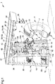
- reference numeral 1 globally indicates a tyre-changing machine, particularly for large wheels, which can be used to remove and fit a tyre 2 from and on the rim 3 of a wheel 4.
- the rim 3 is made of metal material, has a substantially cylindrical shape and comprises at the ends a first flange member 5 and a second flange member 6, which are substantially annular flanges on which the tyre 2 abuts.
- the channel 7 of the rim 3 is defined, i.e. the inner portion of the rim 3 which is not visible from the outside when the tyre 2 is fitted on the rim 3.
- the first flange member 5 and the second flange member 6 face the tyre-changing machine 1 and outwards, respectively, i.e. opposite the tyre-changing machine 1.
- the tyre 2 has a substantially ring-shaped design and comprises a tread 8, which contacts the ground when using the wheel 4.
- the tyre 2 comprises a first flank 9 and a second flank 10, which extend in a substantially transverse manner to the tread 8.
- the first flank 9 and the second flank 10 are provided with a first bead 11 and with a second bead 12, respectively, located on the opposite side with respect to the tread 8.
- first bead 11 and the second bead 12 When mounted on the rim 3, the first bead 11 and the second bead 12 can be juxtaposed to the first flange member 5 and to the second flange member 6, respectively.
- the term "mounted”, when referring to the first bead 11 and/or to the second bead 12, is used to indicate the condition in which the first bead 11 and/or the second bead 12 are located between the first flange member 5 and the second flange member 6, i.e. arranged inside the channel 7.
- the term "removed" relates to the condition wherein the first bead 11 and/or the second bead 12 are located in a space not comprised between the first flange member 5 and the second flange member 6.
- substantially horizontal and substantially vertical mean, respectively, a direction which is comprised within the range ⁇ 40° with respect to the horizontal plane and a direction which is comprised within the range ⁇ 40° with respect to the vertical plane.
- the tyre-changing machine 1 comprises at least one supporting frame 13 resting on the ground comprising at least one post member 14 and at least one cross member 15 associated with the upper end of the post member 14.
- the supporting frame 13 e.g., comprises holding bars made of metal material mutually associated to form a reticular structure resting on the ground and retaining walls (not shown in the figures) associated with the holding bars.
- the post member 14 comprises holding bars having a substantially vertical extension and, below, it is provided with a bedplate directly in contact with the ground.
- the post member 14 comprises a first portion 14a and a second portion 14b, mutually flanked and both extending from the bedplate towards the top of the post member 14.
- the wheel 4 When using the tyre-changing machine 1, the wheel 4 is positioned in the proximity of the first portion 14a while the operator, on the other hand, moves in the proximity of the second portion 14b.
- the cross member 15 comprises holding bars having a substantially horizontal extension which extend in a cantilevered fashion from the post member 14 outwards.
- the cross member 15 protrudes from the first portion 14a; this way there are no objects protruding from the second portion 14b that may interfere with the operator's activities.
- the tyre-changing machine 1 comprises gripping and setting in rotation means 16 associated with the supporting frame 13, adapted to grip the wheel 4 and to move the rim 3 in rotation around a substantially horizontal axis of rotation R.
- substantially horizontal is intended to indicate a direction that is comprised within the range ⁇ 40° with respect to the horizontal plane.
- the axis of rotation R is inclined by a first angle ⁇ with respect to the horizontal plane, wherein the first angle ⁇ can vary from -40° (condition wherein the axis of rotation R extends from the post member 14 downwards) to +40° (condition wherein the axis of rotation R extends from the post member 14 upwards), passing e.g. through 0° (condition wherein the axis of rotation R is perfectly horizontal).
- the first angle ⁇ has an amplitude ranging from 0° to 35°, or from 1 to 10°, or from 3° to 7°, and even better equal to 5°.
- first angle ⁇ greater than zero means that the wheel 4 is partially inclined towards the tyre-changing machine 1, when mounted on the gripping and setting in rotation means 16, thus limiting the occurrence of unpleasant accidents caused by the accidental fall of the wheel 4 due to its possible detachment from the gripping and setting in rotation means 16.
- the gripping and setting in rotation means 16 comprises:
- the gripping and setting in rotation means 16 are located at the first portion 14a.
- the gripping unit 17 comprises a disc-shaped member 22 mounted centrally on the transmission shaft 21.
- the jaws 18 are mounted on the edge of the disc-shaped member 22 in a substantially radial manner.
- jaws 18 are present in a different number; for example, there may be two jaws 18 located in diametrically opposite positions or three jaws 18 staggered by 120°, or six jaws 18 staggered by 60°.
- Each jaw 18 is rotatable with respect to the disc-shaped member 22 around an axis substantially orthogonal to the axis of rotation R, so as to grip the rim 3.
- the tyre-changing machine 1 comprises movement means 23, associated with the supporting frame 13 and adapted to move the gripping and setting in rotation means 16 along a substantially vertical direction of lifting/lowering L.
- the movement means 23 are located at the point where the first portion 14a is located.
- substantially vertical indicates a direction that is comprised in the range ⁇ 40° with respect to the vertical plane.
- the direction of lifting/lowering L is inclined by a second angle ⁇ with respect to the vertical plane, wherein the second angle ⁇ may vary between -40° (condition wherein the direction of lifting/lowering L extends from the bedplate of the post member 14 upwards, moving away from the second portion 14b), and +40° (condition wherein the direction of lifting/lowering L extends from the bedplate of the post member 14 upwards, approaching the second portion 14b), passing e.g. through 0° (condition wherein the direction of lifting/lowering L is perfectly vertical).
- the second angle ⁇ has a width ranging from 0° to -20°, or from -15° to -5°, or from -12° to -8°, and even better equal to -10°.
- the movement means 23 usefully comprise at least one sliding rail 24 associated with the post member 14 and having a substantially vertical extension.
- the sliding rail 24 comprises two tubular members extending between the top and the bedplate of the post member 14.
- the gripping and setting in rotation means 16 comprise at least one sliding member 25 which is engaged on the sliding rail 24 in a sliding manner along the direction of lifting/lowering L.
- the sliding member 25 is substantially a slide, sliding along the tubular members.
- the movement means 23 comprise at least one actuator device 26 associated with the supporting frame 13 and with the sliding member 25 for the movement of the sliding member 25 on the sliding rail 24.
- actuator devices 26 mounted at the upper end of the post member 14.
- Each actuator device 26 is a hydraulic cylinder provided with a stem extending along a substantially vertical direction.
- actuator devices 26 there is a different number of actuator devices 26, e.g. only one actuator device 26 may be located centrally with respect to the sliding member 25.
- actuator devices 26 can be of different types, e.g. pneumatic cylinders.
- the tyre-changing machine 1 comprises at least one first bead-breaking assembly 27 and at least a second bead-breaking assembly 28 associated below the cross member 15 and adapted to remove the first bead 11 and the second bead 12 when both beads 11, 12 are mounted on the rim 3 and to grip simultaneously the tyre 2 in a delivery configuration, wherein the tyre 2 is kept suspended below the cross member 15, when at least the second bead 12 is removed from the rim 3.
- the first bead-breaking assembly 27 and the second bead-breaking assembly 28 comprise a first arm 29 and a second arm 30 respectively, both associated with one end below the cross member 15 and protruding downwards.
- the first bead-breaking assembly 27 and the second bead-breaking assembly 28 comprise a first bead-breaking device 31 and a second bead-breaking device 32 respectively, associated with the free end of the first arm 29 and of the second arm 30.
- the bead-breaking devices 31, 32 have a substantially truncated-cone shape and comprise, at one side opposite the arms 29, 30 a protruding portion 33 having a substantially annular shape.
- the first bead-breaking device 31 is forcefully fitted between the first bead 11 and the first flange member 5, while the second bead-breaking device 32 is forcefully fitted between the second bead 12 and the second flange member 6, thus promoting the detachment of the beads 11, 12 themselves.
- the tyre-changing machine 1 comprises sliding means 34 associated with the supporting frame 13 and adapted to make the first bead-breaking assembly 27 and the second bead-breaking assembly 28 slide with respect to the cross member 15 along a sliding direction S substantially parallel to the axis of rotation R.
- the sliding means 34 comprise:
- the first rail unit 35 comprises two bar members.
- the second rail unit 38 conveniently coincides with the first rail unit 35 and, in actual facts, both the slides 36, 39 slide on the same rail unit.
- the first rail unit 35 may, e.g., comprise a different number of bars on which the first slide 36 slides.
- the second rail unit 38 can be independent of the first rail unit 35, comprising, for example, bar members on which only the second slide 39 slides.
- the first arm 29 is fixed to the first slide 36 and the second arm 30 is fixed to the second slide 39.
- the first actuator member 37 and the second actuator member 40 are hydraulic cylinders that allow the first slide 36 and the second slide 39 to move along the sliding direction S, thus allowing the first bead-breaking assembly 27 and the second bead-breaking assembly 28 to slide with respect to the cross member 15.
- the tyre-changing machine 1 advantageously comprises at least one management and control unit 41 operationally connected to the sliding means 34 and configured to make the first bead-breaking assembly 27 and the second bead-breaking assembly 28 slide simultaneously in the delivery configuration to move the tyre 2 away from the rim 3.
- the management and control unit 41 in the particular embodiment shown in the figures, is associated with the post member 14 at the second portion 14b and is substantially an electronic processor that manages the operation of the tyre-changing machine 1.
- the management and control unit 41 controls, in particular, the operation of the sliding means 34.
- the tyre 2 as mentioned above, is in the delivery configuration when at least the second bead 12 is removed, i.e. it has ridden over the second flange member 6.
- the tyre 2 is no longer permanently associated with the rim 3 and may sag out at the point where the second flange member 6 is located.
- the sliding means 34 move the second bead-breaking assembly 28 so that it abuts on the second flank 10 and holds the tyre 2.
- the delivery configuration also indicates the condition wherein both the beads 11, 12 are removed and the tyre 2 is moved away from the rim 3.
- first bead-breaking assembly 27 and the second bead-breaking assembly 28 have to be brought closer together to abut on the first flank 9 and on the second flank 10 respectively, and grip the tyre 2, then they have to slide simultaneously in the direction of moving away from the post member 14 so as to drag the tyre 2 away from the rim 3 and, at the same time, prevent it from falling to the ground.
- the management and control unit 41 controls the operation of the first actuator member 37 and of the second actuator member 40, thus modifying the sliding level of the first slide 36 and of the second slide 39 with respect to the cross member 15.
- the tyre-changing machine 1 comprises position detection means 42, 43, 44 associated with the supporting frame 13, connected to the management and control unit 41 and adapted to detect the position of the gripping and setting in rotation means 16, of the first bead-breaking assembly 27 and of the second bead-breaking assembly 28 with respect to the supporting frame 13.
- the position detection means 42, 43, 44 comprise first linear transducers 42, located in the proximity of the first rail unit 35, and second linear transducers 43, located in the proximity of the second rail unit 38.
- the first linear transducers 42 detect the distance of the first slide 36 from the post member 14 and the second linear transducers 43 detect the distance of the second slide 39 from the post member 14.
- the first linear transducers 42 and the second linear transducers 43 communicate these data to the management and control unit 41.
- the management and control unit 41 can control, in a targeted manner, the operation of the first actuator member 37 and of the second actuator member 40, thus locating the first bead-breaking assembly 27 and the second bead-breaking assembly 28 in a suitable position to ensure the correct operation of the tyre-changing machine 1.
- the management and control unit 41 also controls the operation of the movement means 23 and, specifically, controls the operation of the actuator device 26.
- the position detection means 42, 43, 44 comprise third linear transducers 44 located in the proximity of the sliding rail 24 which detect the height of the sliding member 25 and communicate this data to the management and control unit 41.
- the management and control unit 41 controls, if necessary, the actuator device 26, thus modifying the height of the sliding member 25.
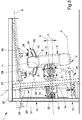
- the tyre-changing machine 1 comprises:
- the movement assembly 46 conveniently comprises:
- the holding member 47 is substantially plate-shaped and is hinged at the lower end of the post member 14.
- the first actuation unit 49 is associated with the holding member 47 and allows the rotation thereof, positioning it alternately in a first substantially vertical position and in a second substantially horizontal position.
- the shift member 48 comprises a plate 48a to which two bars 48b with substantially horizontal extension are attached and which lie on a plane substantially parallel to the lying plane of the holding member 47.
- the bars 48b can slide inside two sleeves 47a attached to one end of the holding member 47 along the thrust direction P.
- the thrust assembly 45 is secured to the plate 48a and, therefore, also slides along the thrust direction P with respect to the holding member 47.
- the second actuation unit 50 comprises a hydraulic cylinder which is attached to the holding member 47 and to the plate 48a and allows the plate 48a to slide along the thrust direction P and the bars 48b to slide inside the sleeves 47a.
- the holding member 47 is located in the first position and the bars 48b do not protrude from the holding member 47.
- the plate 48a is made to slide so that the bars 48b cantilever out of the holding member 47, thanks to the intervention of the second actuation unit 50, and the holding member 47 is made to rotate thanks to the intervention of the first actuation unit 49.
- the second actuation unit 50 makes the plate 48a slide again towards the holding member 47; this way the thrust assembly 45 exerts a pressure on the tyre 2 along the thrust direction P, at the point where the second flank 10 is located.
- the thrust assembly 45 comprises at least one roller 51 associated at one end with the shift member 48 and rotatable with respect to the shift member 48 around a rolling axis T substantially incident and perpendicular to the axis of rotation R when the thrust assembly 45 is in the thrust configuration.
- the thrust assembly 45 comprises a small arm 52 attached at one end to the plate 48a and on the opposite end of which the roller 51 is mounted in a rotatable manner.
- the rolling axis of the roller 51 coincides with the longitudinal axis of the small arm 52.
- the rolling axis T takes different orientations in space depending on the positioning of the thrust assembly 45.
- this special positioning is particularly advantageous when using the tyre-changing machine 1.
- the tyre-changing machine 1 comprises sensor means 53 operationally connected to the management and control unit 41 and adapted to detect the position of the thrust assembly 45 with respect to the supporting frame 13.
- the sensor means 53 comprises a fourth linear transducer 53 which is mounted on the holding member 47 along the thrust direction P and detects the distance of the thrust assembly 45 from the holding member 47.
- the management and control unit 41 controls the operation of the movement assembly 46 depending on the position of the thrust assembly 45 and, specifically, adjusts the first actuation unit 49 and the second actuation unit 50, controlling the thrust that the thrust assembly 45 exerts on the second flank 10.
- the tyre-changing machine 1 comprises at least one user interface 54 connected to the management and control unit 41 for the control of the tyre-changing machine 1 by an operator.
- the user interface 54 conveniently comprises means for entering the diameter of the rim 3 by the operator.
- the management and control unit 41 automatically controls the operation of the tyre-changing machine 1 thanks to its special configuration and to the data provided by the position detection means 42, 43, 44 and by the sensor means 53.
- the operator through the user interface 54, enters the diameter of the rim 3 which is sent to the management and control unit 41.
- the management and control unit 41 controls the movement means 23, in particular the actuator device 26, which determine the sliding of the gripping and setting in rotation means 16 along the direction of lifting/lowering L by positioning them at a height related to the diameter of the rim 3 entered.
- the operator makes the wheel 4 roll on the ground and keeps it in a vertical position, i.e. with the tread 8 contacting the ground, and positions the wheel 4 in the proximity of the gripping and setting in rotation means 16.
- the gripping and setting in rotation means 16 contact the rim 3 and, precisely, the jaws 18 grasp the rim 3 itself.
- the movement means 23 lift the gripping and setting in rotation means 16, thus also lifting the wheel 4 previously hooked by the gripping unit 17, until it reaches a first height.
- the management and control unit 41 controls the sliding means 34 by determining the sliding of the first bead-breaking assembly 27 and of the second bead-breaking assembly 28 towards the tyre 2.
- the first bead-breaking device 31 and the second bead-breaking device 32 contact the first flange member 5 and the second flange member 6, respectively.
- the tyre-changing machine 1 conveniently comprises pressure sensors that detect the contact between the bead-breaking devices 31 and 32 and the flange members 5, 6, thus achieving controlled contact between the bead-breaking device 31 and 32 and the flange members 5, 6.
- the first linear transducer 42 and the second linear transducer 43 communicate the position of the first bead-breaking assembly 27 and of the second bead-breaking assembly 28 to the management and control unit 41, which is able to derive the width of the rim 3, i.e. the distance between the flange members 5, 6.
- the width of the rim 3, together with the rim diameter, is a datum used by the management and control unit 41 to position the moving parts of the tyre-changing machine 1 at the optimal distances from the rim 3 and from the tyre 2 to carry out automatic operation.
- the movement means 23 then lower the gripping and setting in rotation means 16 to a second height, so that the first bead-breaking device 31 and the second bead-breaking device 32 abut on the first bead 11 and on the second bead 12, respectively.
- the sliding means 34 continue to make the first bead-breaking assembly 27 and the second bead-breaking assembly 28 slide towards each other, so that the first bead 11 and the second bead 12 move away from the first flange member 5 and from the second flange member 6 ( Figure 3 ).
- the setting in rotation of the wheel 4 by the gripping and setting in rotation means 16 allows moving the beads 11, 12 away from the flange members 5, 6 along the entire circumferential perimeter of the rim 3, so that the wheel 4 is removed.
- the bead-breaking operation is carried out first on one bead and then on the other bead, although it is possible to perform the simultaneous bead-breaking of both beads 11, 12.
- the operator can possibly spread a lubricant between the beads 11, 12 and the flange members 5, 6 thus promoting the removal of the tyre 2.
- the second bead-breaking assembly 28 is moved away from the tyre 2 and positioned in the proximity thereof so as to hold the tyre 2 when positioned in the delivery configuration.
- the thrust assembly 45 is positioned in the thrust configuration and the roller 51 abuts on the second flank 10.
- the sliding means 34 move the first bead-breaking assembly 27 towards the first flank 9 and the movement assembly 46 makes the thrust assembly 45 slide along the thrust direction P towards the second flank 10 ( Figure 4 ).
- first bead-breaking assembly 27 and the thrust assembly 45 exert two thrusts in substantially parallel but opposite directions on the tyre 2, so as to promote the removal of the second bead 12 and its coming out of the channel 7 of the rim 3.
- the gripping and setting in rotation means 16 set the rim 3 in rotation around the axis of rotation R, thus promoting the removal of the second bead 12 around the entire circumferential perimeter of the rim 3.
- the roller 51 rolls around the rolling axis T without substantially grazing on the second flank 10, except for an extremely small extent, so as not to damage the tyre 2.
- the special positioning of the rolling axis T when the thrust assembly 45 is in the thrust configuration, i.e. substantially incident and orthogonal to the axis of rotation R, allows increasing the contact surface between the roller 51 and the second flank 10, to promote the rolling of the roller 51 on the tyre 2 and to keep the tyre 2 inside the channel 7, in order to promote the removal of the tyre 2 itself ( Figure 5 ).
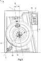
- the second bead-breaking assembly 28 is located in the proximity of the tyre 2 so that it comes in contact with the second flank 10 and holds the tyre 2 as soon as the second bead 12 has been removed, i.e. when it completely rides over the second flange member 6 and the tyre 2 switches to the delivery configuration ( Figure 6 ).
- both the bead-breaking assemblies 27, 28 are moved synchronously so as to move away from the post member 14 and drag the first bead 11 beyond the second flange member 6, so as to move the tyre 2 away from the rim 3 ( Figure 7 ) and then release it in a controlled manner in a position which is not close to the rim 3.
- the release of the tyre 2 takes place in a very safe condition because, when released, the tyre 2 falls standing in an obstacle-free area and when the operator is ready to receive it, i.e. not suddenly.
- the tyre-changing machine 1 can provide that the release of the tyre 2 occurs only after the enabling command by the operator via the user interface 54.
- the tyre-changing machine according to the invention can also operate almost completely automatically; the operator is in fact required to enter only the rim diameter (and, if necessary, the enabling command to release the removed tyre) while all other commands are given by the management and control unit.
Landscapes
- Engineering & Computer Science (AREA)
- Mechanical Engineering (AREA)
- Tires In General (AREA)
- Vehicle Body Suspensions (AREA)
Applications Claiming Priority (1)
| Application Number | Priority Date | Filing Date | Title |
|---|---|---|---|
| IT102019000007034A IT201900007034A1 (it) | 2019-05-20 | 2019-05-20 | Macchina smontagomme, in particolare per ruote di grandi dimensioni |
Publications (1)
| Publication Number | Publication Date |
|---|---|
| EP3741591A1 true EP3741591A1 (fr) | 2020-11-25 |
Family
ID=67875974
Family Applications (1)
| Application Number | Title | Priority Date | Filing Date |
|---|---|---|---|
| EP20175400.9A Withdrawn EP3741591A1 (fr) | 2019-05-20 | 2020-05-19 | Machine à changer les pneus, en particulier pour les grandes roues |
Country Status (2)
| Country | Link |
|---|---|
| EP (1) | EP3741591A1 (fr) |
| IT (1) | IT201900007034A1 (fr) |
Cited By (1)
| Publication number | Priority date | Publication date | Assignee | Title |
|---|---|---|---|---|
| IT202100016793A1 (it) | 2021-06-25 | 2022-12-25 | Devel Srl | Macchina smontagomme, in particolare per ruote di grandi dimensioni |
Citations (7)
| Publication number | Priority date | Publication date | Assignee | Title |
|---|---|---|---|---|
| EP0042363A1 (fr) * | 1980-06-12 | 1981-12-23 | Snap-on Equipment Srl a unico socio. | Appareil pour le montage et démontage de pneumatiques |
| US4606393A (en) * | 1983-05-10 | 1986-08-19 | Corghi Electromeccanica S.P.A. | Tire removal machine with a simultaneously movable tool carrying head and automatic centering unit |
| JPH09123717A (ja) * | 1995-10-31 | 1997-05-13 | Onodani Kiko Kk | タイヤ着脱装置 |
| EP1040941A2 (fr) * | 1999-04-02 | 2000-10-04 | BUTLER ENGINEERING & MARKETING S.r.l. | Machine à changer les pneumatiques d'un véhicule utilitaire |
| EP1052120A1 (fr) * | 1999-05-14 | 2000-11-15 | GIULIANO S.r.l. | Station polyvalente pour le montage et le démontage de pneumatiques conventionnels et spéciaux |
| EP1364814A2 (fr) * | 2002-05-23 | 2003-11-26 | BUTLER ENGINEERING & MARKETING S.r.l. | Machine de montage de pneumatiques et de décoincement des bourrelets pour roues de véhicules utilitaires |
| EP1623850A1 (fr) | 2004-08-03 | 2006-02-08 | SICAM S.r.l. | Machine de montage de pneumatiques |
-
2019
- 2019-05-20 IT IT102019000007034A patent/IT201900007034A1/it unknown
-
2020
- 2020-05-19 EP EP20175400.9A patent/EP3741591A1/fr not_active Withdrawn
Patent Citations (7)
| Publication number | Priority date | Publication date | Assignee | Title |
|---|---|---|---|---|
| EP0042363A1 (fr) * | 1980-06-12 | 1981-12-23 | Snap-on Equipment Srl a unico socio. | Appareil pour le montage et démontage de pneumatiques |
| US4606393A (en) * | 1983-05-10 | 1986-08-19 | Corghi Electromeccanica S.P.A. | Tire removal machine with a simultaneously movable tool carrying head and automatic centering unit |
| JPH09123717A (ja) * | 1995-10-31 | 1997-05-13 | Onodani Kiko Kk | タイヤ着脱装置 |
| EP1040941A2 (fr) * | 1999-04-02 | 2000-10-04 | BUTLER ENGINEERING & MARKETING S.r.l. | Machine à changer les pneumatiques d'un véhicule utilitaire |
| EP1052120A1 (fr) * | 1999-05-14 | 2000-11-15 | GIULIANO S.r.l. | Station polyvalente pour le montage et le démontage de pneumatiques conventionnels et spéciaux |
| EP1364814A2 (fr) * | 2002-05-23 | 2003-11-26 | BUTLER ENGINEERING & MARKETING S.r.l. | Machine de montage de pneumatiques et de décoincement des bourrelets pour roues de véhicules utilitaires |
| EP1623850A1 (fr) | 2004-08-03 | 2006-02-08 | SICAM S.r.l. | Machine de montage de pneumatiques |
Cited By (2)
| Publication number | Priority date | Publication date | Assignee | Title |
|---|---|---|---|---|
| IT202100016793A1 (it) | 2021-06-25 | 2022-12-25 | Devel Srl | Macchina smontagomme, in particolare per ruote di grandi dimensioni |
| WO2022269499A1 (fr) * | 2021-06-25 | 2022-12-29 | Devel Srl | Machine à changer les pneus, en particulier pour grandes roues |
Also Published As
| Publication number | Publication date |
|---|---|
| IT201900007034A1 (it) | 2020-11-20 |
Similar Documents
| Publication | Publication Date | Title |
|---|---|---|
| EP2181867B1 (fr) | Machine de changement de roues pour la fixation et le retrait de roues de véhicules | |
| EP3137362B1 (fr) | Dispositif de mesure d'essieux de véhicules ferroviaires | |
| EP2113761B1 (fr) | Machine pour équilibrer les roues de véhicule | |
| EP2629992B1 (fr) | Machine de démontage de pneu | |
| US4726108A (en) | Device to replace rolls and apparatus on rolling stands having rolls supported at one end | |
| EP2233325A1 (fr) | Machine pour placer et enlever des pneus de jantes de véhicules | |
| EP2524819B1 (fr) | Unité de démonte-talons pour machines de changement de pneus | |
| EP3075577B1 (fr) | Machine destinée à monter et à démonter des pneus de roues de véhicules | |
| EP3741591A1 (fr) | Machine à changer les pneus, en particulier pour les grandes roues | |
| EP2527166B1 (fr) | Unité de démonte-talons pour machines de changement de pneus | |
| EP2927028B1 (fr) | Machine permettant de monter/retirer un pneumatique | |
| EP2995478B1 (fr) | Machine destinée à monter et à démonter des pneus de roues de véhicules | |
| EP2062753A1 (fr) | Machine pour placer et supprimer des pneus de jantes avec appareil de levage | |
| US20020164238A1 (en) | Lifting unit for tire vehicle wheels | |
| EP3293020B1 (fr) | Machine de changement de pneu | |
| ITMO980232A1 (it) | Macchina per smontare e montare pneumatici. | |
| EP0052586A2 (fr) | Dispositif pour faciliter le montage et le démontage des roues lourdes de véhicules automobiles | |
| EP3608129B1 (fr) | Procede de demontage des pneus de roue de vehicule | |
| EP2756969A1 (fr) | Machine destinée à démonter des pneus de jantes de véhicules ou destinée à monter des pneus sur une jante de véhicule | |
| JP2020059496A (ja) | 車両ホイール、特にトラックのホイールを取り付けおよび/または取り外すための機械 | |
| EP2995476B1 (fr) | Tête fonctionnelle pour placer et retirer des pneus de véhicules | |
| US5017111A (en) | Apparatus for charging a tire heating press | |
| EP4359232A1 (fr) | Machine à changer les pneus, en particulier pour grandes roues | |
| EP1852273A1 (fr) | Dispositif auxiliaire pour les machines d'un atelier adapté pour lever les roues de véhicules, particulièrement pour les appareils de changements de pneus et similaires | |
| JPH1086617A (ja) | タイヤのデマウント装置 |
Legal Events
| Date | Code | Title | Description |
|---|---|---|---|
| PUAI | Public reference made under article 153(3) epc to a published international application that has entered the european phase |
Free format text: ORIGINAL CODE: 0009012 |
|
| STAA | Information on the status of an ep patent application or granted ep patent |
Free format text: STATUS: THE APPLICATION HAS BEEN PUBLISHED |
|
| AK | Designated contracting states |
Kind code of ref document: A1 Designated state(s): AL AT BE BG CH CY CZ DE DK EE ES FI FR GB GR HR HU IE IS IT LI LT LU LV MC MK MT NL NO PL PT RO RS SE SI SK SM TR |
|
| AX | Request for extension of the european patent |
Extension state: BA ME |
|
| STAA | Information on the status of an ep patent application or granted ep patent |
Free format text: STATUS: THE APPLICATION IS DEEMED TO BE WITHDRAWN |
|
| 18D | Application deemed to be withdrawn |
Effective date: 20210526 |