EP3741495A1 - Method and system for laser additive manufacturing based on keyhole effects - Google Patents
Method and system for laser additive manufacturing based on keyhole effects Download PDFInfo
- Publication number
- EP3741495A1 EP3741495A1 EP19740837.0A EP19740837A EP3741495A1 EP 3741495 A1 EP3741495 A1 EP 3741495A1 EP 19740837 A EP19740837 A EP 19740837A EP 3741495 A1 EP3741495 A1 EP 3741495A1
- Authority
- EP
- European Patent Office
- Prior art keywords
- welding wire
- laser beam
- substrate
- additive manufacturing
- normal line
- Prior art date
- Legal status (The legal status is an assumption and is not a legal conclusion. Google has not performed a legal analysis and makes no representation as to the accuracy of the status listed.)
- Granted
Links
Images

Classifications
-
- B—PERFORMING OPERATIONS; TRANSPORTING
- B33—ADDITIVE MANUFACTURING TECHNOLOGY
- B33Y—ADDITIVE MANUFACTURING, i.e. MANUFACTURING OF THREE-DIMENSIONAL [3D] OBJECTS BY ADDITIVE DEPOSITION, ADDITIVE AGGLOMERATION OR ADDITIVE LAYERING, e.g. BY 3D PRINTING, STEREOLITHOGRAPHY OR SELECTIVE LASER SINTERING
- B33Y10/00—Processes of additive manufacturing
-
- B—PERFORMING OPERATIONS; TRANSPORTING
- B23—MACHINE TOOLS; METAL-WORKING NOT OTHERWISE PROVIDED FOR
- B23K—SOLDERING OR UNSOLDERING; WELDING; CLADDING OR PLATING BY SOLDERING OR WELDING; CUTTING BY APPLYING HEAT LOCALLY, e.g. FLAME CUTTING; WORKING BY LASER BEAM
- B23K26/00—Working by laser beam, e.g. welding, cutting or boring
- B23K26/34—Laser welding for purposes other than joining
- B23K26/342—Build-up welding
-
- B—PERFORMING OPERATIONS; TRANSPORTING
- B33—ADDITIVE MANUFACTURING TECHNOLOGY
- B33Y—ADDITIVE MANUFACTURING, i.e. MANUFACTURING OF THREE-DIMENSIONAL [3D] OBJECTS BY ADDITIVE DEPOSITION, ADDITIVE AGGLOMERATION OR ADDITIVE LAYERING, e.g. BY 3D PRINTING, STEREOLITHOGRAPHY OR SELECTIVE LASER SINTERING
- B33Y30/00—Apparatus for additive manufacturing; Details thereof or accessories therefor
-
- Y—GENERAL TAGGING OF NEW TECHNOLOGICAL DEVELOPMENTS; GENERAL TAGGING OF CROSS-SECTIONAL TECHNOLOGIES SPANNING OVER SEVERAL SECTIONS OF THE IPC; TECHNICAL SUBJECTS COVERED BY FORMER USPC CROSS-REFERENCE ART COLLECTIONS [XRACs] AND DIGESTS
- Y02—TECHNOLOGIES OR APPLICATIONS FOR MITIGATION OR ADAPTATION AGAINST CLIMATE CHANGE
- Y02P—CLIMATE CHANGE MITIGATION TECHNOLOGIES IN THE PRODUCTION OR PROCESSING OF GOODS
- Y02P10/00—Technologies related to metal processing
- Y02P10/25—Process efficiency
Definitions
- the present disclosure relates to a method and system for laser additive manufacturing based on keyhole effects and belong to the field of advanced manufacturing technology.
- laser additive manufacturing As a kind of advanced manufacturing technology, laser additive manufacturing has the advantages of low energy consumption, short flow, integration of forming and property control and etc.. Laser additive manufacturing has gradually realized laser rapid prototyping manufacturing and laser direct additive manufacturing since its development in 1980s. Laser additive manufacturing has changed the forming and processing mode of traditional metal parts, especially the parts with high performance and complex configuration. Because of its high utilization rate of materials, short manufacturing cycle and excellent performance of formed parts, laser additive manufacturing is widely used in aerospace, shipbuilding and other fields.
- Laser additive manufacturing can be divided into two categories according to the different states of metal materials during forming, one is represented by selective laser melting (SLM), in which powder is pre-laid before metal powder deposition; and the other is represented by direct metal deposition, in which the material is sent into the melting pool in real time in the metal material deposition process.
- SLM selective laser melting
- direct metal deposition in which the material is sent into the melting pool in real time in the metal material deposition process.
- Selective laser melting is a technology that scans the pre-laid metal powder with a high-energy laser beam according to the predetermined scanning path to melt it completely, and then cools and solidifies it for formation.
- SLM Selective laser melting
- the greatest advantage of SLM technology is that it can form complex shape parts, and secondly it can manufacture small batch of parts within a certain volume range rapidly. But its manufacturing cost is directly proportional to the processing time. Therefore, when forming large parts, the processing cost will greatly increase due to the increase of processing time.
- the selective laser melting technology has strict requirements on the processing conditions, and its processing needs to be completed in the vacuum chamber, which limits its development in practical production.
- the metal powder is used as the raw material, the high-energy laser is used as the energy source, according to the predetermined processing path, the metal powder that is fed synchronously is melted, solidified and deposited layer by layer, so as to realize the direct manufacturing of metal parts.
- the parts formed by this method have good compactness, but due to the interaction between laser and powder, the laser energy is attenuated, so the effective utilization rate of energy is low.
- the fed powder enters the melting pool, resulting in low deposition efficiency of the powder feeding additive manufacturing. For example, W. Syed et al.
- the present disclosure aims to provide a method which can improve the forming efficiency of wire feeding laser additive manufacturing, and solve the problems of high laser energy reflectivity and low formation efficiency in the wire feeding process.
- the laser additive manufacturing method includes the following steps.
- a welding wire and a laser beam are arranged, at certain angles, at two sides of a normal line of a substrate.
- a light spot generated by the laser beam is applied on a position of the welding wire that has a certain distance from the substrate.
- the laser beam produces a deep penetration melting keyhole.
- the welding wire absorbs most of the energy of the laser beam and is heated and melted in a deep penetration melting mod.
- the welding wire transits energy to a surface of the substrate to form a melting pool and a cladding layer in a first area.
- the laser beam irradiates a second area of the substrate to preheat the second area of the substrate in a thermal conduction mode.
- the method adopts a front wire feeding mode, and the welding wire, the laser beam and a normal line of the substrate are in one plane.
- An angle between the welding wire and the normal line is a first angle, and an angle between the laser beam and the normal line is a second angel.
- the first angle between the welding wire and the normal line is 5° ⁇ 30°.
- the second angle between the laser beam and the normal line is 15° ⁇ 45°.
- the position of the light spot applied on the welding wire is 1-5mm away from the surface of the workpiece.
- a system for laser additive manufacturing based on keyhole effects incudes a substrate, a welding wire and a laser beam.
- the substrate has a surface suitable for additive manufacturing.
- the welding wire and the laser beam are placed, at certain angles, at two sides of a normal line of the substrate.
- a light spot generated by the laser beam acts on the welding wire and produces a deep penetration melting keyhole, such that the welding wire absorbs the energy of the laser beam in the deep penetration melting mode and transits energy to the substrate to form a melting pool 3 and a cladding layer 2 in a first area.
- the laser beam After passing through the welding wire, the laser beam irradiates a second area of the substrate to preheat the second area of the substrate in a thermal conduction mode.
- the system adopts a front wire feeding mode, and the welding wire, the laser beam 5 and the normal line of the substrate are in one plane.
- An angle between the welding wire and the normal line is a first angle, and an angle between the laser beam and the normal line is a second angel.
- the first angle between the welding wire and the normal line is 5° ⁇ 30°.
- the second angle between the laser beam and the normal line is 15° ⁇ 45°.
- the light spot acting on the welding wire is 1 ⁇ 5mm away from the surface of the substrate.
- the present disclosure may provide one or more technical advantages.
- the melting rate of the welding wire is greatly increased, and the formation efficiency is greatly improved.
- a system for a method for wire feeding additive manufacturing based on the keyhole effects includes a substrate 1.
- a welding wire 7 and a laser beam 5 are arranged at two different sides of a normal line of the substrate 1.
- the welding wire 7 is arranged with a certain angle with the normal line of the substrate 1.
- the laser beam is also arranged with a certain angle with the normal line of the substrate 1.
- the laser beam 5 acts on the welding wire 7 and produces a deep penetration melting keyhole 4 on the welding wire 7.
- the welding wire 7 absorbs the energy of the laser beam 5 in a deep penetration melting mode and transits energy to the substrate 1 to form a melting pool 3 and a cladding layer 2.
- the laser beam 5 irradiates the surface of the substrate 1 to preheat a workpiece in a thermal conduction mode.
- the substrate 1 in the system is the surface of the workpiece where the additive manufacturing is implemented, and can be made of any suitable metal material.
- the welding wire 7 in the system is supplied from the guide nozzle 6, the movement process of the guide nozzle 6 and the wire feeding speed of the welding wire 7 can be controlled in any applicable way, such as using a special or general control system (not shown in the figure).
- the welding wire 7 in the system is made of material suitable for the material of the substrate 1.
- the welding wire 7 is made of the same material as the substrate 1 to form a cladding layer 2 with the same material as the substrate 1.
- the laser beam 5 in the system can be generated by any applicable laser.
- the laser beam 5 is guided to a position above the substrate 1 through a light guiding system such as an optical fiber, and generates a light spot in a set area through an optical focusing system.
- the power, focusing position and other parameters of the laser beam 5 can be set by using the relevant control device (not shown in the figure), so that the laser, the light guiding system and the optical focusing system can be controlled.
- the parameters are set in such a manner that required heating effect is provided at a required position of the welding wire 7.
- the welding wire 7 and the laser beam 5 in the system are configured in a front wire feeding mode. That is, the welding wire is fed in front of the normal line along a system scanning direction, and the laser beam 5 is on the other side of the normal line.
- An included angle between the welding wire 7 and the normal line is a first angle
- an included angle between the laser beam 5 and the normal line is a second angle.
- the welding wire 7 and the laser beam 5 may share the same three-dimensional moving device, or each of the welding wire 7 and the laser beam 5 is equipped with a three-dimensional moving device.
- Each of the welding wire 7 and the laser beam 5 moves according to a predetermined trajectory, so as to form a cladding layer 2 with a predetermined shape on the substrate 1.
- the first angle between the welding wire 7 and the normal line is 5° ⁇ 30°.
- the second angle between the laser beam 5 and the normal line is 5° ⁇ 30°.
- the light spot of the laser beam 5 focused on the welding wire is 1-5mm away from the substrate 1.
- keyhole effect refers to that the laser beam acts on the welding wire with a high power density, so that the welding wire is heated and melted to a temperature above the boiling point, resulting in violent evaporation of the material, a deep penetration melting keyhole is formed on the welding wire because of the vapor pressure, and the laser beam can pass through the welding wire through the keyhole.
- deep penetration melting mode refers to that the laser beam heats the welding wire with a high power, the welding wire absorbs the heat of the laser beam and then melts deeply, thus forming a deep penetration melting keyhole on the welding wire, and the laser beam can pass through the welding wire via the deep penetration melting keyhole.
- thermal conduction mode refers to that the laser beam heats the surface of the substrate with a small power, the surface of the substrate only melts in a limited depth after absorbing the heat of the laser beam, and transmits heat to the surrounding of the laser irradiation position and the interior of the substrate through heat conduction.
- Embodiment one The basic principle of the embodiment of this disclosure is shown in FIG. 1 , and will not be repeated here.
- the YLS-6000 fiber laser of IPG company is used.
- the welding wire is made of 316L stainless steel with a diameter of 1.2mm.
- a 200 mm focusing mirror is used.
- a front wire feeding mode is adopted.
- the laser beam and the normal line of the workpiece are in the same plane.
- the angle between the welding wire and the normal line of the workpiece is adjusted to 15°, the angle between the laser beam and the normal line of the workpiece is adjusted to 30°.
- the position of the light spot acting on the welding wire is 2mm away from the surface of the workpiece.
- the shielding gas is Ar, and the gas flow rate is 20L / min.
- the process parameters are as follows: laser power is 3kw, wire feeding speed is 3m/min, scanning speed is 1.5m/min.
- the cross-sectional optics microscope photo of the formed part of embodiment one is shown in FIG. 2 .
- the formed part of this embodiment is in a good state, and the metal deposition efficiency is 0.72kg / (h-kW), which is about double times of the traditional laser additive manufacturing.
- Embodiment two The basic principle of the embodiment of this disclosure is shown in FIG. 1 , and will not be repeated here.
- the YLS-6000 fiber laser of IPG company is used.
- the welding wire is made of 316L stainless steel with a diameter of 1.2mm.
- a 200 mm focusing mirror is used.
- a front wire feeding mode is adopted.
- the laser beam and the normal line of the workpiece are in the same plane.
- the angle between the welding wire and the normal line of the workpiece is adjusted to 30°, and the angle between the laser beam and the normal line of the workpiece is adjusted to 30°.
- the position of the light spot acting on the welding wire is 2mm away from the surface of the workpiece.
- the shielding gas is Ar, and the gas flow rate is 20L / min.
- the process parameters are as follows: laser power is 3kw, wire feeding speed is 4m/min, scanning speed is 1.5m/min.
- the cross-sectional optics microscope photo of the formed part of embodiment two is shown in FIG. 2 , the formed part is in good state, and the metal deposition efficiency is 0.72kg / (h-kW), which is about triple times of the traditional laser additive manufacturing.
- Embodiment three The basic principle of the embodiment of this disclosure is shown in FIG. 1 , and will not be repeated here.
- the YLS-6000 fiber laser of IPG company is used.
- the welding wire is made of 316L stainless steel with a diameter of 1.2mm.
- a 200 mm focusing mirror is used.
- a front wire feeding mode is adopted.
- the laser beam and the normal line of the workpiece are in the same plane.
- the angle between the welding wire and the normal line of the workpiece is adjusted to 15°, and the angle between the laser beam and the normal line of the workpiece is adjusted to 30°.
- the position of the light spot acting on the welding wire is 2.5mm away from the surface of the workpiece.
- the shielding gas is Ar, and the gas flow rate is 20L / min.
- the process parameters are as follows: laser power is 3kw, wire feeding speed is 4.5m/min, scanning speed is 1.5m/min.
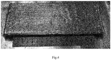
- the appearance of the formed part in embodiment three is shown in FIG. 4 .
Landscapes
- Engineering & Computer Science (AREA)
- Physics & Mathematics (AREA)
- Optics & Photonics (AREA)
- Plasma & Fusion (AREA)
- Mechanical Engineering (AREA)
- Chemical & Material Sciences (AREA)
- Manufacturing & Machinery (AREA)
- Materials Engineering (AREA)
- Laser Beam Processing (AREA)
Abstract
Description
- This application claims priority to a PCT patent application No.
PCT/CN2019/070902 filed on January 8, 2019 - The present disclosure relates to a method and system for laser additive manufacturing based on keyhole effects and belong to the field of advanced manufacturing technology.
- As a kind of advanced manufacturing technology, laser additive manufacturing has the advantages of low energy consumption, short flow, integration of forming and property control and etc.. Laser additive manufacturing has gradually realized laser rapid prototyping manufacturing and laser direct additive manufacturing since its development in 1980s. Laser additive manufacturing has changed the forming and processing mode of traditional metal parts, especially the parts with high performance and complex configuration. Because of its high utilization rate of materials, short manufacturing cycle and excellent performance of formed parts, laser additive manufacturing is widely used in aerospace, shipbuilding and other fields.
- Laser additive manufacturing can be divided into two categories according to the different states of metal materials during forming, one is represented by selective laser melting (SLM), in which powder is pre-laid before metal powder deposition; and the other is represented by direct metal deposition, in which the material is sent into the melting pool in real time in the metal material deposition process.
- Selective laser melting (SLM) is a technology that scans the pre-laid metal powder with a high-energy laser beam according to the predetermined scanning path to melt it completely, and then cools and solidifies it for formation. Compared with traditional machining, the greatest advantage of SLM technology is that it can form complex shape parts, and secondly it can manufacture small batch of parts within a certain volume range rapidly. But its manufacturing cost is directly proportional to the processing time. Therefore, when forming large parts, the processing cost will greatly increase due to the increase of processing time. At the same time, the selective laser melting technology has strict requirements on the processing conditions, and its processing needs to be completed in the vacuum chamber, which limits its development in practical production.
- Compared with selective laser melting, there are two main ways of laser melting deposition, one is synchronous powder feeding, the other is wire feeding. In the process of powder feeding laser additive manufacturing, the metal powder is used as the raw material, the high-energy laser is used as the energy source, according to the predetermined processing path, the metal powder that is fed synchronously is melted, solidified and deposited layer by layer, so as to realize the direct manufacturing of metal parts. The parts formed by this method have good compactness, but due to the interaction between laser and powder, the laser energy is attenuated, so the effective utilization rate of energy is low. At the same time, not all the fed powder enters the melting pool, resulting in low deposition efficiency of the powder feeding additive manufacturing. For example, W. Syed et al. studied the influence of different process parameters on the deposition efficiency of 316L stainless steel powder. The powder deposition efficiency increased with the increase of power, and the average deposition efficiency was about 0.21 kg / (H·kW) (W.Syed, Pinkerton A J, Li L. A comparative study of wire feeding and powder feeding in direct diode laser deposition for rapid prototyping[J]. Applied surface science, 2005, 247(1): 268-276.). For the wire feeding additive manufacturing, the cladding efficiency of the wire feeding additive manufacturing can reach almost 100% under the appropriate process conditions, which can greatly improve the utilization rate of the material. However, the laser absorption rate of the metal wire is affected by many factors, and the affecting factors are more complex. In addition, due to the reflection of the wire, the energy of the laser acting on the wire and melting it is greatly reduced, resulting in low deposition efficiency. By using 316L stainless steel welding wire to implement formation on the stainless steel part, the influence of different process parameters on laser additive manufacturing was studied by Faming Shen et al.. The deposition efficiency was about 0.27kg / (H·kW) (Faming Shen. Characteristics of wire-based laser additive manufacturing for stainless steel[D]. Harbin Institute of Technology.2015).
- How to realize high efficiency laser additive manufacturing and improve energy utilization and formation efficiency is a difficult problem to be solved. Therefore, this field needs a new laser additive manufacturing method that uses the deep laser welding principle and improves the forming efficiency.
- The present disclosure aims to provide a method which can improve the forming efficiency of wire feeding laser additive manufacturing, and solve the problems of high laser energy reflectivity and low formation efficiency in the wire feeding process.
- The technical scheme of the disclosure is as follows.
- According to one aspect of the present disclosure, there is provided a method for laser additive manufacturing based on keyhole effects. The laser additive manufacturing method includes the following steps.
- A welding wire and a laser beam are arranged, at certain angles, at two sides of a normal line of a substrate. A light spot generated by the laser beam is applied on a position of the welding wire that has a certain distance from the substrate. The laser beam produces a deep penetration melting keyhole. The welding wire absorbs most of the energy of the laser beam and is heated and melted in a deep penetration melting mod. The welding wire transits energy to a surface of the substrate to form a melting pool and a cladding layer in a first area. After passing through the welding wire, the laser beam irradiates a second area of the substrate to preheat the second area of the substrate in a thermal conduction mode.
- In an embodiment, the method adopts a front wire feeding mode, and the welding wire, the laser beam and a normal line of the substrate are in one plane. An angle between the welding wire and the normal line is a first angle, and an angle between the laser beam and the normal line is a second angel.
- In an embodiment, the first angle between the welding wire and the normal line is 5° ∼ 30°.
- In an embodiment, the second angle between the laser beam and the normal line is 15° ∼ 45°.
- In an embodiment, the position of the light spot applied on the welding wire is 1-5mm away from the surface of the workpiece.
- According to another aspect of the present disclosure, there is provided a system for laser additive manufacturing based on keyhole effects. The system incudes a substrate, a welding wire and a laser beam.
- The substrate has a surface suitable for additive manufacturing. The welding wire and the laser beam are placed, at certain angles, at two sides of a normal line of the substrate. A light spot generated by the laser beam acts on the welding wire and produces a deep penetration melting keyhole, such that the welding wire absorbs the energy of the laser beam in the deep penetration melting mode and transits energy to the substrate to form a
melting pool 3 and acladding layer 2 in a first area. After passing through the welding wire, the laser beam irradiates a second area of the substrate to preheat the second area of the substrate in a thermal conduction mode. - In an embodiment, the system adopts a front wire feeding mode, and the welding wire, the
laser beam 5 and the normal line of the substrate are in one plane. An angle between the welding wire and the normal line is a first angle, and an angle between the laser beam and the normal line is a second angel. - In an embodiment, the first angle between the welding wire and the normal line is 5° ∼ 30°.
- In an embodiment, the second angle between the laser beam and the normal line is 15° ∼ 45°.
- In an embodiment, the light spot acting on the welding wire is 1∼5mm away from the surface of the substrate.
- In accordance with the abovementioned, the present disclosure may provide one or more technical advantages.
- In one aspect, by heating and melting the welding wire in the deep penetration melting mode, the melting rate of the welding wire is greatly increased, and the formation efficiency is greatly improved.
- In another aspect, by heating and melting a workpiece in the thermal conduction mode, the occurrence of defects, such as air hole and the like, can be effectively avoided.
-
-
FIG. 1 is a schematic diagram of a method of laser additive manufacturing based on keyhole effect; -
FIG. 2 is an optics microscope photo of a manufactured part in an embodiment one; -
FIG. 3 is an optics microscope photo of a manufactured part in an embodiment two; and -
FIG. 4 is an appearance view of a manufactured part in an embodiment three. - 1 substrate, 2 cladding layer, 3 melting pool, 4 deep penetration melting keyhole, 5 laser beam, 6 guide nozzle, 7 welding wire, 8 preheating area.
- Several preferred embodiments of the present disclosure will be described in detail in conjunction with the accompanying drawings as follows, however, the present disclosure is intended to encompass any substitutions, modifications, equivalents, etc., made thereto without departing from the spirit and scope of the present disclosure. In order to provide those skilled in the art with thorough understanding of the present disclosure, particular details will be described below in the exemplary embodiments of the present disclosure, although those skilled in the art can understand the present disclosure without the description of these details.
- As illustrated in
FIG. 1 , according to the present disclosure, a system for a method for wire feeding additive manufacturing based on the keyhole effects is provided. The illustrated system includes asubstrate 1. Awelding wire 7 and alaser beam 5 are arranged at two different sides of a normal line of thesubstrate 1. Thewelding wire 7 is arranged with a certain angle with the normal line of thesubstrate 1. The laser beam is also arranged with a certain angle with the normal line of thesubstrate 1. Thelaser beam 5 acts on thewelding wire 7 and produces a deeppenetration melting keyhole 4 on thewelding wire 7. Thewelding wire 7 absorbs the energy of thelaser beam 5 in a deep penetration melting mode and transits energy to thesubstrate 1 to form amelting pool 3 and acladding layer 2. After passing through thewelding wire 7, thelaser beam 5 irradiates the surface of thesubstrate 1 to preheat a workpiece in a thermal conduction mode. - The
substrate 1 in the system is the surface of the workpiece where the additive manufacturing is implemented, and can be made of any suitable metal material. - The
welding wire 7 in the system is supplied from theguide nozzle 6, the movement process of theguide nozzle 6 and the wire feeding speed of thewelding wire 7 can be controlled in any applicable way, such as using a special or general control system (not shown in the figure). - The
welding wire 7 in the system is made of material suitable for the material of thesubstrate 1. In an optional embodiment, thewelding wire 7 is made of the same material as thesubstrate 1 to form acladding layer 2 with the same material as thesubstrate 1. - The
laser beam 5 in the system can be generated by any applicable laser. Thelaser beam 5 is guided to a position above thesubstrate 1 through a light guiding system such as an optical fiber, and generates a light spot in a set area through an optical focusing system. The power, focusing position and other parameters of thelaser beam 5 can be set by using the relevant control device (not shown in the figure), so that the laser, the light guiding system and the optical focusing system can be controlled. The parameters are set in such a manner that required heating effect is provided at a required position of thewelding wire 7. - The
welding wire 7 and thelaser beam 5 in the system are configured in a front wire feeding mode. That is, the welding wire is fed in front of the normal line along a system scanning direction, and thelaser beam 5 is on the other side of the normal line. An included angle between thewelding wire 7 and the normal line is a first angle, and an included angle between thelaser beam 5 and the normal line is a second angle. Thewelding wire 7 and thelaser beam 5 may share the same three-dimensional moving device, or each of thewelding wire 7 and thelaser beam 5 is equipped with a three-dimensional moving device. Each of thewelding wire 7 and thelaser beam 5 moves according to a predetermined trajectory, so as to form acladding layer 2 with a predetermined shape on thesubstrate 1. - In an optional embodiment, the first angle between the
welding wire 7 and the normal line is 5° ∼ 30°. In an optional embodiment, the second angle between thelaser beam 5 and the normal line is 5° ∼ 30°. The light spot of thelaser beam 5 focused on the welding wire is 1-5mm away from thesubstrate 1. - The term "keyhole effect" mentioned here refers to that the laser beam acts on the welding wire with a high power density, so that the welding wire is heated and melted to a temperature above the boiling point, resulting in violent evaporation of the material, a deep penetration melting keyhole is formed on the welding wire because of the vapor pressure, and the laser beam can pass through the welding wire through the keyhole.
- The term "deep penetration melting mode" mentioned here refers to that the laser beam heats the welding wire with a high power, the welding wire absorbs the heat of the laser beam and then melts deeply, thus forming a deep penetration melting keyhole on the welding wire, and the laser beam can pass through the welding wire via the deep penetration melting keyhole.
- The term "thermal conduction mode" mentioned here refers to that the laser beam heats the surface of the substrate with a small power, the surface of the substrate only melts in a limited depth after absorbing the heat of the laser beam, and transmits heat to the surrounding of the laser irradiation position and the interior of the substrate through heat conduction.
- The method and system of wire feeding laser additive manufacturing based on the keyhole effect will be further described in combination with specific embodiments.
- Embodiment one: The basic principle of the embodiment of this disclosure is shown in
FIG. 1 , and will not be repeated here. In this embodiment, the YLS-6000 fiber laser of IPG company is used. The welding wire is made of 316L stainless steel with a diameter of 1.2mm. A 200 mm focusing mirror is used. A front wire feeding mode is adopted. The laser beam and the normal line of the workpiece are in the same plane. The angle between the welding wire and the normal line of the workpiece is adjusted to 15°, the angle between the laser beam and the normal line of the workpiece is adjusted to 30°. The position of the light spot acting on the welding wire is 2mm away from the surface of the workpiece. The shielding gas is Ar, and the gas flow rate is 20L / min. The process parameters are as follows: laser power is 3kw, wire feeding speed is 3m/min, scanning speed is 1.5m/min. The cross-sectional optics microscope photo of the formed part of embodiment one is shown inFIG. 2 . The formed part of this embodiment is in a good state, and the metal deposition efficiency is 0.72kg / (h-kW), which is about double times of the traditional laser additive manufacturing. - Embodiment two: The basic principle of the embodiment of this disclosure is shown in
FIG. 1 , and will not be repeated here. In this embodiment, the YLS-6000 fiber laser of IPG company is used. The welding wire is made of 316L stainless steel with a diameter of 1.2mm. A 200 mm focusing mirror is used. A front wire feeding mode is adopted. The laser beam and the normal line of the workpiece are in the same plane. The angle between the welding wire and the normal line of the workpiece is adjusted to 30°, and the angle between the laser beam and the normal line of the workpiece is adjusted to 30°. The position of the light spot acting on the welding wire is 2mm away from the surface of the workpiece. The shielding gas is Ar, and the gas flow rate is 20L / min. The process parameters are as follows: laser power is 3kw, wire feeding speed is 4m/min, scanning speed is 1.5m/min. The cross-sectional optics microscope photo of the formed part of embodiment two is shown inFIG. 2 , the formed part is in good state, and the metal deposition efficiency is 0.72kg / (h-kW), which is about triple times of the traditional laser additive manufacturing. - Embodiment three: The basic principle of the embodiment of this disclosure is shown in
FIG. 1 , and will not be repeated here. In this embodiment, the YLS-6000 fiber laser of IPG company is used. The welding wire is made of 316L stainless steel with a diameter of 1.2mm. A 200 mm focusing mirror is used. A front wire feeding mode is adopted. The laser beam and the normal line of the workpiece are in the same plane. The angle between the welding wire and the normal line of the workpiece is adjusted to 15°, and the angle between the laser beam and the normal line of the workpiece is adjusted to 30°. The position of the light spot acting on the welding wire is 2.5mm away from the surface of the workpiece. The shielding gas is Ar, and the gas flow rate is 20L / min. The process parameters are as follows: laser power is 3kw, wire feeding speed is 4.5m/min, scanning speed is 1.5m/min. The appearance of the formed part in embodiment three is shown inFIG. 4 . - The above are merely preferred embodiments of the present invention, and those skilled in the art can understand that the present invention is not limited thereto. Without departing from the principle of the present invention, the present invention can also make several improvements and modifications, and these improvements and modifications should also be regarded as within the protection scope of the present invention.
Claims (10)
- A method for laser additive manufacturing based on keyhole effects, comprising:arranging a welding wire (7) and a laser beam (5) at two sides of a normal line of a substrate (1) at certain angles with respect to the normal line respectively;applying a light spot of the laser beam (5) on a position of the welding wire (7) having a certain distance from the substrate (1) to produce a deep penetration melting keyhole (4), the welding wire 7 absorbing energy of the laser beam (5), being heated and melted in a deep penetration welding mode, and the welding wire (7) transiting energy to the substrate (1) to form a melting pool 3 and a cladding layer (2) at a first area; andafter passing through the welding wire (7), the laser beam (5) irradiating a second area of the substrate (1) to preheat the second area of the substrate (1) in a thermal conduction mode.
- The method for laser additive manufacturing based on keyhole effects according to claim 1, wherein the method adopts a front wire feeding mode, and the welding wire (7), the laser beam (5) and the normal line of the substrate (1) are in one plane, an angle between the welding wire (7) and the normal line is a first angle, and an angle between the laser beam (5) and the normal line is a second angel.
- The method for laser additive manufacturing based on keyhole effects according to claim 2, wherein the first angle between the welding wire (7) and the normal line is 5° ∼30°.
- The method for laser additive manufacturing based on keyhole effects according to claim 2, wherein the second angle between the laser beam (5) and the normal line is 15° ∼45°.
- The method for laser additive manufacturing based on keyhole effects according to claim 1, wherein the position of the welding wire (7) where the light spot is applied is 1∼5mm away from a surface of a workpiece.
- A system for laser additive manufacturing based on keyhole effects, comprising:a substrate (1), having a surface suitable for additive manufacturing; anda welding wire (7) and a laser beam (5), arranged at two sides of a normal line of the substrate (1) at certain angles with respect to the normal line respectively,wherein the laser beam (5) is applied on the welding wire (7)and produces a deep penetration melting keyhole (4), the welding wire (7) absorbs energy of the laser beam (5) and is heated and melted in a deep penetration melting mode, and the welding wire (7) transits energy to the substrate (1) to form a melting pool (3) and a cladding layer (2) at a first area;after passing through the welding wire (7), the laser beam 5 irradiates a second area of the substrate (1) to preheat the second area of the substrate (1) in a thermal conduction mode.
- The system for laser additive manufacturing based on keyhole effects according to claim 6, wherein the system adopts a front wire feeding mode, and the welding wire (7), the laser beam (5) and the normal line of the substrate (1) are in one plane, an angle between the welding wire (7) and the normal line is a first angle, and an angle between the laser beam (5) and the normal line is a second angel.
- The system for laser additive manufacturing based on keyhole effects according to claim 7, wherein the first angle between the welding wire (7) and the normal line is 5° ∼30°.
- The system for laser additive manufacturing based on keyhole effects according to claim 7, wherein the second angle between the laser beam (5) and the normal line is 15° ∼45°.
- The system for laser additive manufacturing based on keyhole effects according to claim 6, wherein a light spot is applied on a position of the welding wire (7) that is 1∼5mm away from a surface of a workpiece.
Applications Claiming Priority (2)
| Application Number | Priority Date | Filing Date | Title |
|---|---|---|---|
| CN201810047415.2A CN108188581B (en) | 2018-01-18 | 2018-01-18 | A wire-feeding laser additive manufacturing method |
| PCT/CN2019/070902 WO2019141115A1 (en) | 2018-01-18 | 2019-01-08 | Method and system for laser additive manufacturing based on keyhole effects |
Publications (3)
| Publication Number | Publication Date |
|---|---|
| EP3741495A1 true EP3741495A1 (en) | 2020-11-25 |
| EP3741495A4 EP3741495A4 (en) | 2021-12-01 |
| EP3741495B1 EP3741495B1 (en) | 2023-03-29 |
Family
ID=62589572
Family Applications (1)
| Application Number | Title | Priority Date | Filing Date |
|---|---|---|---|
| EP19740837.0A Active EP3741495B1 (en) | 2018-01-18 | 2019-01-08 | Method and system for laser additive manufacturing based on keyhole effects |
Country Status (5)
| Country | Link |
|---|---|
| US (1) | US12023758B2 (en) |
| EP (1) | EP3741495B1 (en) |
| JP (1) | JP6910092B2 (en) |
| CN (1) | CN108188581B (en) |
| WO (1) | WO2019141115A1 (en) |
Families Citing this family (8)
| Publication number | Priority date | Publication date | Assignee | Title |
|---|---|---|---|---|
| CN108188581B (en) * | 2018-01-18 | 2019-12-13 | 北京工业大学 | A wire-feeding laser additive manufacturing method |
| CN112867579B (en) * | 2018-10-19 | 2023-04-04 | 三菱电机株式会社 | Additive manufacturing apparatus and additive manufacturing method |
| CN109807417B (en) * | 2019-03-24 | 2021-03-16 | 北京工业大学 | A method of laser active cutting welding wire to control droplet temperature |
| CN111299837A (en) * | 2019-11-27 | 2020-06-19 | 北京工业大学 | Efficient laser additive manufacturing method based on wire thermal conduction welding |
| DE102019219276A1 (en) * | 2019-12-10 | 2021-06-10 | Eos Gmbh Electro Optical Systems | Hatch reversal with keyhole handover |
| WO2022003189A1 (en) * | 2020-07-02 | 2022-01-06 | Oerlikon Surface Solutions Ag, Pfäffikon | Method to produce high corrosion and wear resistant cast iron components by using laser cladding |
| US12350741B2 (en) | 2020-10-16 | 2025-07-08 | Arcam Ab | Systems and methods for weld tapering at a trailing edge using time multiplexing |
| CN113278962B (en) * | 2021-04-16 | 2022-12-09 | 北京工业大学 | Preparation method of laser cladding layer of cutter edge based on powder-cored welding wire deep melting mode |
Family Cites Families (17)
| Publication number | Priority date | Publication date | Assignee | Title |
|---|---|---|---|---|
| JP2000117469A (en) * | 1998-10-13 | 2000-04-25 | Nissan Motor Co Ltd | Overlaying method |
| JP4664569B2 (en) * | 2002-05-08 | 2011-04-06 | 株式会社東芝 | Method and apparatus for sealing surface defects |
| GB0302399D0 (en) * | 2003-02-03 | 2003-03-05 | Rolls Royce Plc | Laser deposition |
| JP4848921B2 (en) * | 2006-10-13 | 2011-12-28 | パナソニック株式会社 | Composite welding method and composite welding equipment |
| JP5104945B2 (en) * | 2008-11-27 | 2012-12-19 | パナソニック株式会社 | Composite welding method and composite welding equipment |
| US10105780B2 (en) * | 2012-07-06 | 2018-10-23 | Lincoln Global, Inc. | Method and system of using a consumable and a heat source with a weld puddle |
| US20140042131A1 (en) * | 2012-08-10 | 2014-02-13 | Lincoln Global, Inc. | Laser welding consumable |
| JP5797633B2 (en) * | 2012-10-31 | 2015-10-21 | 株式会社神戸製鋼所 | Arc welding apparatus, constant voltage characteristic welding power source and arc welding method |
| JP6261406B2 (en) * | 2014-03-20 | 2018-01-17 | 日立造船株式会社 | Welding apparatus and welding method |
| CN104551391B (en) * | 2014-12-25 | 2017-03-01 | 北京石油化工学院 | A kind of laser enhancing GMAW droplet transfer control method under water |
| US10994371B2 (en) * | 2016-02-24 | 2021-05-04 | Mitsubishi Electric Research Laboratories, Inc. | System and method for depositing a metal to form a three-dimensional part |
| US10799986B2 (en) * | 2016-06-27 | 2020-10-13 | Illinois Tool Works Inc. | Wide path welding, cladding, additive manufacturing |
| CN106001823B (en) * | 2016-07-29 | 2018-11-13 | 大族激光科技产业集团股份有限公司 | Laser Overlaying welding method and device |
| US20180154442A1 (en) * | 2016-12-06 | 2018-06-07 | Velo3D, Inc. | Optics, detectors, and three-dimensional printing |
| CN107414302A (en) * | 2017-08-10 | 2017-12-01 | 上海交通大学 | A kind of laser heated filament complex welding method |
| CN107414303A (en) * | 2017-08-10 | 2017-12-01 | 上海交通大学 | A kind of laser scanning combination laser heating wire TIG complex welding method |
| CN108188581B (en) * | 2018-01-18 | 2019-12-13 | 北京工业大学 | A wire-feeding laser additive manufacturing method |
-
2018
- 2018-01-18 CN CN201810047415.2A patent/CN108188581B/en active Active
-
2019
- 2019-01-08 US US16/962,708 patent/US12023758B2/en active Active
- 2019-01-08 EP EP19740837.0A patent/EP3741495B1/en active Active
- 2019-01-08 WO PCT/CN2019/070902 patent/WO2019141115A1/en not_active Ceased
- 2019-01-08 JP JP2020537536A patent/JP6910092B2/en active Active
Also Published As
| Publication number | Publication date |
|---|---|
| US12023758B2 (en) | 2024-07-02 |
| US20200346303A1 (en) | 2020-11-05 |
| CN108188581B (en) | 2019-12-13 |
| JP2021510122A (en) | 2021-04-15 |
| EP3741495B1 (en) | 2023-03-29 |
| CN108188581A (en) | 2018-06-22 |
| WO2019141115A1 (en) | 2019-07-25 |
| EP3741495A4 (en) | 2021-12-01 |
| JP6910092B2 (en) | 2021-07-28 |
Similar Documents
| Publication | Publication Date | Title |
|---|---|---|
| EP3741495B1 (en) | Method and system for laser additive manufacturing based on keyhole effects | |
| EP2424706B2 (en) | Additive layer fabrication method | |
| TWI702105B (en) | Laser processing apparatus and method | |
| CN112404729B (en) | Wire feeding type double-beam laser additive manufacturing method | |
| EP2424707B2 (en) | Additive layer fabrication method | |
| CN106312314B (en) | double laser beam welding system and method | |
| Jia et al. | Experimental study on nanosecond-millisecond combined pulse laser drilling of alumina ceramic with different spot sizes | |
| WO2014121621A1 (en) | A laser quenching method and apparatus | |
| CN202021424U (en) | Laser wire filling welding machine with non-stable cavity and coaxial wire feed | |
| CN103290176B (en) | A kind of multi irradiation laser-quenching method and device | |
| EP2588268A1 (en) | Laser-based lap welding of sheet metal components using laser induced protuberances to control gap | |
| CN204524549U (en) | A kind of bifocus recombination laser welding processing head | |
| CN104827034A (en) | 3D (3-dimensional) printing device | |
| CN204686014U (en) | 3D printing equipment | |
| US9649727B2 (en) | High speed laser cutting of amorphous metals | |
| WO2019119617A1 (en) | High-refractive-index and low-hardness transparent material laser cutting device and method | |
| CN105195893A (en) | Laser welding technology | |
| EP2246143A1 (en) | Additive layer fabrication method | |
| EP2246145A1 (en) | Additive layer fabrication method | |
| Kelkar | Pulsed laser welding | |
| CN111299837A (en) | Efficient laser additive manufacturing method based on wire thermal conduction welding | |
| CN111069786B (en) | Laser grooving device and method | |
| CN203509342U (en) | Laser welding device | |
| Zhou et al. | Vector and temporal manipulation for laser processing efficiency improvement | |
| CN210237778U (en) | A multi-laser source cladding welding device |
Legal Events
| Date | Code | Title | Description |
|---|---|---|---|
| STAA | Information on the status of an ep patent application or granted ep patent |
Free format text: STATUS: THE INTERNATIONAL PUBLICATION HAS BEEN MADE |
|
| PUAI | Public reference made under article 153(3) epc to a published international application that has entered the european phase |
Free format text: ORIGINAL CODE: 0009012 |
|
| STAA | Information on the status of an ep patent application or granted ep patent |
Free format text: STATUS: REQUEST FOR EXAMINATION WAS MADE |
|
| 17P | Request for examination filed |
Effective date: 20200812 |
|
| AK | Designated contracting states |
Kind code of ref document: A1 Designated state(s): AL AT BE BG CH CY CZ DE DK EE ES FI FR GB GR HR HU IE IS IT LI LT LU LV MC MK MT NL NO PL PT RO RS SE SI SK SM TR |
|
| AX | Request for extension of the european patent |
Extension state: BA ME |
|
| DAV | Request for validation of the european patent (deleted) | ||
| DAX | Request for extension of the european patent (deleted) | ||
| A4 | Supplementary search report drawn up and despatched |
Effective date: 20211028 |
|
| RIC1 | Information provided on ipc code assigned before grant |
Ipc: B33Y 30/00 20150101ALI20211022BHEP Ipc: B33Y 10/00 20150101ALI20211022BHEP Ipc: B23K 26/342 20140101AFI20211022BHEP |
|
| GRAP | Despatch of communication of intention to grant a patent |
Free format text: ORIGINAL CODE: EPIDOSNIGR1 |
|
| STAA | Information on the status of an ep patent application or granted ep patent |
Free format text: STATUS: GRANT OF PATENT IS INTENDED |
|
| INTG | Intention to grant announced |
Effective date: 20221024 |
|
| RIN1 | Information on inventor provided before grant (corrected) |
Inventor name: XU, JIEJIE Inventor name: ZOU, JIANGLIN Inventor name: WU, QIANG Inventor name: HUANG, TING Inventor name: XIAO, RONGSHI |
|
| GRAS | Grant fee paid |
Free format text: ORIGINAL CODE: EPIDOSNIGR3 |
|
| GRAA | (expected) grant |
Free format text: ORIGINAL CODE: 0009210 |
|
| STAA | Information on the status of an ep patent application or granted ep patent |
Free format text: STATUS: THE PATENT HAS BEEN GRANTED |
|
| AK | Designated contracting states |
Kind code of ref document: B1 Designated state(s): AL AT BE BG CH CY CZ DE DK EE ES FI FR GB GR HR HU IE IS IT LI LT LU LV MC MK MT NL NO PL PT RO RS SE SI SK SM TR |
|
| REG | Reference to a national code |
Ref country code: CH Ref legal event code: EP |
|
| REG | Reference to a national code |
Ref country code: DE Ref legal event code: R096 Ref document number: 602019026935 Country of ref document: DE |
|
| REG | Reference to a national code |
Ref country code: AT Ref legal event code: REF Ref document number: 1556335 Country of ref document: AT Kind code of ref document: T Effective date: 20230415 |
|
| REG | Reference to a national code |
Ref country code: IE Ref legal event code: FG4D |
|
| REG | Reference to a national code |
Ref country code: LT Ref legal event code: MG9D |
|
| PG25 | Lapsed in a contracting state [announced via postgrant information from national office to epo] |
Ref country code: RS Free format text: LAPSE BECAUSE OF FAILURE TO SUBMIT A TRANSLATION OF THE DESCRIPTION OR TO PAY THE FEE WITHIN THE PRESCRIBED TIME-LIMIT Effective date: 20230329 Ref country code: NO Free format text: LAPSE BECAUSE OF FAILURE TO SUBMIT A TRANSLATION OF THE DESCRIPTION OR TO PAY THE FEE WITHIN THE PRESCRIBED TIME-LIMIT Effective date: 20230629 Ref country code: LV Free format text: LAPSE BECAUSE OF FAILURE TO SUBMIT A TRANSLATION OF THE DESCRIPTION OR TO PAY THE FEE WITHIN THE PRESCRIBED TIME-LIMIT Effective date: 20230329 Ref country code: LT Free format text: LAPSE BECAUSE OF FAILURE TO SUBMIT A TRANSLATION OF THE DESCRIPTION OR TO PAY THE FEE WITHIN THE PRESCRIBED TIME-LIMIT Effective date: 20230329 Ref country code: HR Free format text: LAPSE BECAUSE OF FAILURE TO SUBMIT A TRANSLATION OF THE DESCRIPTION OR TO PAY THE FEE WITHIN THE PRESCRIBED TIME-LIMIT Effective date: 20230329 |
|
| REG | Reference to a national code |
Ref country code: NL Ref legal event code: MP Effective date: 20230329 |
|
| REG | Reference to a national code |
Ref country code: AT Ref legal event code: MK05 Ref document number: 1556335 Country of ref document: AT Kind code of ref document: T Effective date: 20230329 |
|
| PG25 | Lapsed in a contracting state [announced via postgrant information from national office to epo] |
Ref country code: SE Free format text: LAPSE BECAUSE OF FAILURE TO SUBMIT A TRANSLATION OF THE DESCRIPTION OR TO PAY THE FEE WITHIN THE PRESCRIBED TIME-LIMIT Effective date: 20230329 Ref country code: NL Free format text: LAPSE BECAUSE OF FAILURE TO SUBMIT A TRANSLATION OF THE DESCRIPTION OR TO PAY THE FEE WITHIN THE PRESCRIBED TIME-LIMIT Effective date: 20230329 Ref country code: GR Free format text: LAPSE BECAUSE OF FAILURE TO SUBMIT A TRANSLATION OF THE DESCRIPTION OR TO PAY THE FEE WITHIN THE PRESCRIBED TIME-LIMIT Effective date: 20230630 Ref country code: FI Free format text: LAPSE BECAUSE OF FAILURE TO SUBMIT A TRANSLATION OF THE DESCRIPTION OR TO PAY THE FEE WITHIN THE PRESCRIBED TIME-LIMIT Effective date: 20230329 |
|
| PG25 | Lapsed in a contracting state [announced via postgrant information from national office to epo] |
Ref country code: SM Free format text: LAPSE BECAUSE OF FAILURE TO SUBMIT A TRANSLATION OF THE DESCRIPTION OR TO PAY THE FEE WITHIN THE PRESCRIBED TIME-LIMIT Effective date: 20230329 Ref country code: RO Free format text: LAPSE BECAUSE OF FAILURE TO SUBMIT A TRANSLATION OF THE DESCRIPTION OR TO PAY THE FEE WITHIN THE PRESCRIBED TIME-LIMIT Effective date: 20230329 Ref country code: PT Free format text: LAPSE BECAUSE OF FAILURE TO SUBMIT A TRANSLATION OF THE DESCRIPTION OR TO PAY THE FEE WITHIN THE PRESCRIBED TIME-LIMIT Effective date: 20230731 Ref country code: ES Free format text: LAPSE BECAUSE OF FAILURE TO SUBMIT A TRANSLATION OF THE DESCRIPTION OR TO PAY THE FEE WITHIN THE PRESCRIBED TIME-LIMIT Effective date: 20230329 Ref country code: EE Free format text: LAPSE BECAUSE OF FAILURE TO SUBMIT A TRANSLATION OF THE DESCRIPTION OR TO PAY THE FEE WITHIN THE PRESCRIBED TIME-LIMIT Effective date: 20230329 Ref country code: AT Free format text: LAPSE BECAUSE OF FAILURE TO SUBMIT A TRANSLATION OF THE DESCRIPTION OR TO PAY THE FEE WITHIN THE PRESCRIBED TIME-LIMIT Effective date: 20230329 |
|
| PG25 | Lapsed in a contracting state [announced via postgrant information from national office to epo] |
Ref country code: SK Free format text: LAPSE BECAUSE OF FAILURE TO SUBMIT A TRANSLATION OF THE DESCRIPTION OR TO PAY THE FEE WITHIN THE PRESCRIBED TIME-LIMIT Effective date: 20230329 Ref country code: PL Free format text: LAPSE BECAUSE OF FAILURE TO SUBMIT A TRANSLATION OF THE DESCRIPTION OR TO PAY THE FEE WITHIN THE PRESCRIBED TIME-LIMIT Effective date: 20230329 Ref country code: IS Free format text: LAPSE BECAUSE OF FAILURE TO SUBMIT A TRANSLATION OF THE DESCRIPTION OR TO PAY THE FEE WITHIN THE PRESCRIBED TIME-LIMIT Effective date: 20230729 |
|
| REG | Reference to a national code |
Ref country code: DE Ref legal event code: R097 Ref document number: 602019026935 Country of ref document: DE |
|
| PG25 | Lapsed in a contracting state [announced via postgrant information from national office to epo] |
Ref country code: DK Free format text: LAPSE BECAUSE OF FAILURE TO SUBMIT A TRANSLATION OF THE DESCRIPTION OR TO PAY THE FEE WITHIN THE PRESCRIBED TIME-LIMIT Effective date: 20230329 Ref country code: CZ Free format text: LAPSE BECAUSE OF FAILURE TO SUBMIT A TRANSLATION OF THE DESCRIPTION OR TO PAY THE FEE WITHIN THE PRESCRIBED TIME-LIMIT Effective date: 20230329 |
|
| PLBE | No opposition filed within time limit |
Free format text: ORIGINAL CODE: 0009261 |
|
| STAA | Information on the status of an ep patent application or granted ep patent |
Free format text: STATUS: NO OPPOSITION FILED WITHIN TIME LIMIT |
|
| 26N | No opposition filed |
Effective date: 20240103 |
|
| PG25 | Lapsed in a contracting state [announced via postgrant information from national office to epo] |
Ref country code: SI Free format text: LAPSE BECAUSE OF FAILURE TO SUBMIT A TRANSLATION OF THE DESCRIPTION OR TO PAY THE FEE WITHIN THE PRESCRIBED TIME-LIMIT Effective date: 20230329 |
|
| PG25 | Lapsed in a contracting state [announced via postgrant information from national office to epo] |
Ref country code: SI Free format text: LAPSE BECAUSE OF FAILURE TO SUBMIT A TRANSLATION OF THE DESCRIPTION OR TO PAY THE FEE WITHIN THE PRESCRIBED TIME-LIMIT Effective date: 20230329 Ref country code: IT Free format text: LAPSE BECAUSE OF FAILURE TO SUBMIT A TRANSLATION OF THE DESCRIPTION OR TO PAY THE FEE WITHIN THE PRESCRIBED TIME-LIMIT Effective date: 20230329 |
|
| PG25 | Lapsed in a contracting state [announced via postgrant information from national office to epo] |
Ref country code: MC Free format text: LAPSE BECAUSE OF FAILURE TO SUBMIT A TRANSLATION OF THE DESCRIPTION OR TO PAY THE FEE WITHIN THE PRESCRIBED TIME-LIMIT Effective date: 20230329 |
|
| PG25 | Lapsed in a contracting state [announced via postgrant information from national office to epo] |
Ref country code: MC Free format text: LAPSE BECAUSE OF FAILURE TO SUBMIT A TRANSLATION OF THE DESCRIPTION OR TO PAY THE FEE WITHIN THE PRESCRIBED TIME-LIMIT Effective date: 20230329 |
|
| REG | Reference to a national code |
Ref country code: CH Ref legal event code: PL |
|
| PG25 | Lapsed in a contracting state [announced via postgrant information from national office to epo] |
Ref country code: LU Free format text: LAPSE BECAUSE OF NON-PAYMENT OF DUE FEES Effective date: 20240108 |
|
| PG25 | Lapsed in a contracting state [announced via postgrant information from national office to epo] |
Ref country code: LU Free format text: LAPSE BECAUSE OF NON-PAYMENT OF DUE FEES Effective date: 20240108 |
|
| PG25 | Lapsed in a contracting state [announced via postgrant information from national office to epo] |
Ref country code: BE Free format text: LAPSE BECAUSE OF NON-PAYMENT OF DUE FEES Effective date: 20240131 |
|
| PG25 | Lapsed in a contracting state [announced via postgrant information from national office to epo] |
Ref country code: CH Free format text: LAPSE BECAUSE OF NON-PAYMENT OF DUE FEES Effective date: 20240131 |
|
| PG25 | Lapsed in a contracting state [announced via postgrant information from national office to epo] |
Ref country code: CH Free format text: LAPSE BECAUSE OF NON-PAYMENT OF DUE FEES Effective date: 20240131 Ref country code: BE Free format text: LAPSE BECAUSE OF NON-PAYMENT OF DUE FEES Effective date: 20240131 |
|
| REG | Reference to a national code |
Ref country code: BE Ref legal event code: MM Effective date: 20240131 |
|
| PG25 | Lapsed in a contracting state [announced via postgrant information from national office to epo] |
Ref country code: BG Free format text: LAPSE BECAUSE OF FAILURE TO SUBMIT A TRANSLATION OF THE DESCRIPTION OR TO PAY THE FEE WITHIN THE PRESCRIBED TIME-LIMIT Effective date: 20230329 |
|
| PG25 | Lapsed in a contracting state [announced via postgrant information from national office to epo] |
Ref country code: BG Free format text: LAPSE BECAUSE OF FAILURE TO SUBMIT A TRANSLATION OF THE DESCRIPTION OR TO PAY THE FEE WITHIN THE PRESCRIBED TIME-LIMIT Effective date: 20230329 |
|
| PG25 | Lapsed in a contracting state [announced via postgrant information from national office to epo] |
Ref country code: IE Free format text: LAPSE BECAUSE OF NON-PAYMENT OF DUE FEES Effective date: 20240108 |
|
| PG25 | Lapsed in a contracting state [announced via postgrant information from national office to epo] |
Ref country code: IE Free format text: LAPSE BECAUSE OF NON-PAYMENT OF DUE FEES Effective date: 20240108 |
|
| PG25 | Lapsed in a contracting state [announced via postgrant information from national office to epo] |
Ref country code: CY Free format text: LAPSE BECAUSE OF FAILURE TO SUBMIT A TRANSLATION OF THE DESCRIPTION OR TO PAY THE FEE WITHIN THE PRESCRIBED TIME-LIMIT; INVALID AB INITIO Effective date: 20190108 |
|
| PG25 | Lapsed in a contracting state [announced via postgrant information from national office to epo] |
Ref country code: HU Free format text: LAPSE BECAUSE OF FAILURE TO SUBMIT A TRANSLATION OF THE DESCRIPTION OR TO PAY THE FEE WITHIN THE PRESCRIBED TIME-LIMIT; INVALID AB INITIO Effective date: 20190108 |
|
| PG25 | Lapsed in a contracting state [announced via postgrant information from national office to epo] |
Ref country code: TR Free format text: LAPSE BECAUSE OF FAILURE TO SUBMIT A TRANSLATION OF THE DESCRIPTION OR TO PAY THE FEE WITHIN THE PRESCRIBED TIME-LIMIT Effective date: 20230329 |
|
| PGFP | Annual fee paid to national office [announced via postgrant information from national office to epo] |
Ref country code: GB Payment date: 20260127 Year of fee payment: 8 |
|
| PGFP | Annual fee paid to national office [announced via postgrant information from national office to epo] |
Ref country code: DE Payment date: 20260114 Year of fee payment: 8 |
|
| PGFP | Annual fee paid to national office [announced via postgrant information from national office to epo] |
Ref country code: FR Payment date: 20260128 Year of fee payment: 8 |