EP2424707B2 - Additive layer fabrication method - Google Patents
Additive layer fabrication method Download PDFInfo
- Publication number
- EP2424707B2 EP2424707B2 EP10718667.8A EP10718667A EP2424707B2 EP 2424707 B2 EP2424707 B2 EP 2424707B2 EP 10718667 A EP10718667 A EP 10718667A EP 2424707 B2 EP2424707 B2 EP 2424707B2
- Authority
- EP
- European Patent Office
- Prior art keywords
- laser
- substrate
- layers
- specific power
- computer
- Prior art date
- Legal status (The legal status is an assumption and is not a legal conclusion. Google has not performed a legal analysis and makes no representation as to the accuracy of the status listed.)
- Active
Links
Images

Classifications
-
- B—PERFORMING OPERATIONS; TRANSPORTING
- B23—MACHINE TOOLS; METAL-WORKING NOT OTHERWISE PROVIDED FOR
- B23K—SOLDERING OR UNSOLDERING; WELDING; CLADDING OR PLATING BY SOLDERING OR WELDING; CUTTING BY APPLYING HEAT LOCALLY, e.g. FLAME CUTTING; WORKING BY LASER BEAM
- B23K35/00—Rods, electrodes, materials, or media, for use in soldering, welding, or cutting
- B23K35/02—Rods, electrodes, materials, or media, for use in soldering, welding, or cutting characterised by mechanical features, e.g. shape
- B23K35/0222—Rods, electrodes, materials, or media, for use in soldering, welding, or cutting characterised by mechanical features, e.g. shape for use in soldering, brazing
- B23K35/0244—Powders, particles or spheres; Preforms made therefrom
-
- B—PERFORMING OPERATIONS; TRANSPORTING
- B22—CASTING; POWDER METALLURGY
- B22F—WORKING METALLIC POWDER; MANUFACTURE OF ARTICLES FROM METALLIC POWDER; MAKING METALLIC POWDER; APPARATUS OR DEVICES SPECIALLY ADAPTED FOR METALLIC POWDER
- B22F10/00—Additive manufacturing of workpieces or articles from metallic powder
- B22F10/20—Direct sintering or melting
- B22F10/28—Powder bed fusion, e.g. selective laser melting [SLM] or electron beam melting [EBM]
-
- B—PERFORMING OPERATIONS; TRANSPORTING
- B22—CASTING; POWDER METALLURGY
- B22F—WORKING METALLIC POWDER; MANUFACTURE OF ARTICLES FROM METALLIC POWDER; MAKING METALLIC POWDER; APPARATUS OR DEVICES SPECIALLY ADAPTED FOR METALLIC POWDER
- B22F12/00—Apparatus or devices specially adapted for additive manufacturing; Auxiliary means for additive manufacturing; Combinations of additive manufacturing apparatus or devices with other processing apparatus or devices
- B22F12/40—Radiation means
- B22F12/41—Radiation means characterised by the type, e.g. laser or electron beam
- B22F12/43—Radiation means characterised by the type, e.g. laser or electron beam pulsed; frequency modulated
-
- B—PERFORMING OPERATIONS; TRANSPORTING
- B23—MACHINE TOOLS; METAL-WORKING NOT OTHERWISE PROVIDED FOR
- B23K—SOLDERING OR UNSOLDERING; WELDING; CLADDING OR PLATING BY SOLDERING OR WELDING; CUTTING BY APPLYING HEAT LOCALLY, e.g. FLAME CUTTING; WORKING BY LASER BEAM
- B23K26/00—Working by laser beam, e.g. welding, cutting or boring
- B23K26/20—Bonding
- B23K26/32—Bonding taking account of the properties of the material involved
-
- B—PERFORMING OPERATIONS; TRANSPORTING
- B23—MACHINE TOOLS; METAL-WORKING NOT OTHERWISE PROVIDED FOR
- B23K—SOLDERING OR UNSOLDERING; WELDING; CLADDING OR PLATING BY SOLDERING OR WELDING; CUTTING BY APPLYING HEAT LOCALLY, e.g. FLAME CUTTING; WORKING BY LASER BEAM
- B23K26/00—Working by laser beam, e.g. welding, cutting or boring
- B23K26/34—Laser welding for purposes other than joining
- B23K26/342—Build-up welding
-
- B—PERFORMING OPERATIONS; TRANSPORTING
- B29—WORKING OF PLASTICS; WORKING OF SUBSTANCES IN A PLASTIC STATE IN GENERAL
- B29C—SHAPING OR JOINING OF PLASTICS; SHAPING OF MATERIAL IN A PLASTIC STATE, NOT OTHERWISE PROVIDED FOR; AFTER-TREATMENT OF THE SHAPED PRODUCTS, e.g. REPAIRING
- B29C64/00—Additive manufacturing, i.e. manufacturing of three-dimensional [3D] objects by additive deposition, additive agglomeration or additive layering, e.g. by 3D printing, stereolithography or selective laser sintering
- B29C64/10—Processes of additive manufacturing
- B29C64/141—Processes of additive manufacturing using only solid materials
- B29C64/153—Processes of additive manufacturing using only solid materials using layers of powder being selectively joined, e.g. by selective laser sintering or melting
-
- B—PERFORMING OPERATIONS; TRANSPORTING
- B33—ADDITIVE MANUFACTURING TECHNOLOGY
- B33Y—ADDITIVE MANUFACTURING, i.e. MANUFACTURING OF THREE-DIMENSIONAL [3-D] OBJECTS BY ADDITIVE DEPOSITION, ADDITIVE AGGLOMERATION OR ADDITIVE LAYERING, e.g. BY 3-D PRINTING, STEREOLITHOGRAPHY OR SELECTIVE LASER SINTERING
- B33Y10/00—Processes of additive manufacturing
-
- B—PERFORMING OPERATIONS; TRANSPORTING
- B22—CASTING; POWDER METALLURGY
- B22F—WORKING METALLIC POWDER; MANUFACTURE OF ARTICLES FROM METALLIC POWDER; MAKING METALLIC POWDER; APPARATUS OR DEVICES SPECIALLY ADAPTED FOR METALLIC POWDER
- B22F10/00—Additive manufacturing of workpieces or articles from metallic powder
- B22F10/30—Process control
- B22F10/36—Process control of energy beam parameters
-
- B—PERFORMING OPERATIONS; TRANSPORTING
- B22—CASTING; POWDER METALLURGY
- B22F—WORKING METALLIC POWDER; MANUFACTURE OF ARTICLES FROM METALLIC POWDER; MAKING METALLIC POWDER; APPARATUS OR DEVICES SPECIALLY ADAPTED FOR METALLIC POWDER
- B22F12/00—Apparatus or devices specially adapted for additive manufacturing; Auxiliary means for additive manufacturing; Combinations of additive manufacturing apparatus or devices with other processing apparatus or devices
- B22F12/40—Radiation means
- B22F12/41—Radiation means characterised by the type, e.g. laser or electron beam
-
- B—PERFORMING OPERATIONS; TRANSPORTING
- B23—MACHINE TOOLS; METAL-WORKING NOT OTHERWISE PROVIDED FOR
- B23K—SOLDERING OR UNSOLDERING; WELDING; CLADDING OR PLATING BY SOLDERING OR WELDING; CUTTING BY APPLYING HEAT LOCALLY, e.g. FLAME CUTTING; WORKING BY LASER BEAM
- B23K2103/00—Materials to be soldered, welded or cut
- B23K2103/50—Inorganic material, e.g. metals, not provided for in B23K2103/02 – B23K2103/26
-
- C—CHEMISTRY; METALLURGY
- C23—COATING METALLIC MATERIAL; COATING MATERIAL WITH METALLIC MATERIAL; CHEMICAL SURFACE TREATMENT; DIFFUSION TREATMENT OF METALLIC MATERIAL; COATING BY VACUUM EVAPORATION, BY SPUTTERING, BY ION IMPLANTATION OR BY CHEMICAL VAPOUR DEPOSITION, IN GENERAL; INHIBITING CORROSION OF METALLIC MATERIAL OR INCRUSTATION IN GENERAL
- C23C—COATING METALLIC MATERIAL; COATING MATERIAL WITH METALLIC MATERIAL; SURFACE TREATMENT OF METALLIC MATERIAL BY DIFFUSION INTO THE SURFACE, BY CHEMICAL CONVERSION OR SUBSTITUTION; COATING BY VACUUM EVAPORATION, BY SPUTTERING, BY ION IMPLANTATION OR BY CHEMICAL VAPOUR DEPOSITION, IN GENERAL
- C23C16/00—Chemical coating by decomposition of gaseous compounds, without leaving reaction products of surface material in the coating, i.e. chemical vapour deposition [CVD] processes
- C23C16/44—Chemical coating by decomposition of gaseous compounds, without leaving reaction products of surface material in the coating, i.e. chemical vapour deposition [CVD] processes characterised by the method of coating
- C23C16/48—Chemical coating by decomposition of gaseous compounds, without leaving reaction products of surface material in the coating, i.e. chemical vapour deposition [CVD] processes characterised by the method of coating by irradiation, e.g. photolysis, radiolysis, particle radiation
- C23C16/483—Chemical coating by decomposition of gaseous compounds, without leaving reaction products of surface material in the coating, i.e. chemical vapour deposition [CVD] processes characterised by the method of coating by irradiation, e.g. photolysis, radiolysis, particle radiation using coherent light, UV to IR, e.g. lasers
-
- C—CHEMISTRY; METALLURGY
- C23—COATING METALLIC MATERIAL; COATING MATERIAL WITH METALLIC MATERIAL; CHEMICAL SURFACE TREATMENT; DIFFUSION TREATMENT OF METALLIC MATERIAL; COATING BY VACUUM EVAPORATION, BY SPUTTERING, BY ION IMPLANTATION OR BY CHEMICAL VAPOUR DEPOSITION, IN GENERAL; INHIBITING CORROSION OF METALLIC MATERIAL OR INCRUSTATION IN GENERAL
- C23C—COATING METALLIC MATERIAL; COATING MATERIAL WITH METALLIC MATERIAL; SURFACE TREATMENT OF METALLIC MATERIAL BY DIFFUSION INTO THE SURFACE, BY CHEMICAL CONVERSION OR SUBSTITUTION; COATING BY VACUUM EVAPORATION, BY SPUTTERING, BY ION IMPLANTATION OR BY CHEMICAL VAPOUR DEPOSITION, IN GENERAL
- C23C24/00—Coating starting from inorganic powder
-
- Y—GENERAL TAGGING OF NEW TECHNOLOGICAL DEVELOPMENTS; GENERAL TAGGING OF CROSS-SECTIONAL TECHNOLOGIES SPANNING OVER SEVERAL SECTIONS OF THE IPC; TECHNICAL SUBJECTS COVERED BY FORMER USPC CROSS-REFERENCE ART COLLECTIONS [XRACs] AND DIGESTS
- Y02—TECHNOLOGIES OR APPLICATIONS FOR MITIGATION OR ADAPTATION AGAINST CLIMATE CHANGE
- Y02P—CLIMATE CHANGE MITIGATION TECHNOLOGIES IN THE PRODUCTION OR PROCESSING OF GOODS
- Y02P10/00—Technologies related to metal processing
- Y02P10/25—Process efficiency
Description
- This invention relates to an additive layer fabrication (ALF) method, that is to say a method in which successive layers of material are added on top of each other so as to build-up a three-dimensional structure. The invention is particularly but not exclusively applicable to selective laser melting, and may be applied both to the manufacture of new articles, or to the repair of used ones.
- In selective laser melting a laser beam is used to melt a controlled amount of powdered (usually metallic) material on a substrate, so as to form a layer of fused material thereon. By moving the laser beam relative to the substrate along a predetermined path, the layer can be defined in two dimensions on the substrate, the width of the layer being determined by the diameter of the laser beam where it strikes the substrate. Repeating the movement of the laser along all or part of its path enables further layers of material to be deposited, thereby fabricating a three-dimensional object.
- Selective laser melting hitherto has been performed using continuous wave (CW) lasers, typically Nd: YAG lasers operating at 1064 nm. This can achieve high material deposition rates particularly suited for repair applications or where a subsequent machining operation is acceptable in order to achieve the finished component. The method does not however lend itself to the production of near-net-shape components to close tolerances and with a high quality surface finish. Preferred embodiments of one aspect of the present invention seek to address this shortcoming.
- Modulating the laser beam pulse enables the amount of heat applied to the powder to be accurately and precisely controlled.
- By using a pulse-modulated laser, much finer control of the fabrication process can be achieved. We have found it possible to produce layers as little as 10µm thick.
- By "traversing" we mean moving along a predetermined path e.g. under computer control. Traversing is not limited to moving in a straight line from one edge of the substrate to the other.
- The quantity of powdered material which is fused to form the layer, and thus the thickness of the layer depends inter alia on the power per unit area (specific power) applied by the laser to the material as it traverses the substrate and on the other operating parameters of the laser, the powder feed rate and the traverse speed. Modulating the pulse shape and/or duration provides a means of controlling the specific power for a given traverse rate. By modulating the laser beam pulse during a traverse, the thickness of the layer deposited during that traverse can be varied. This can result in decrease in manufacturing time compared to a method in which the layer thickness is constant and vertical profiling is achieved by depositing a layer only during part of the traverse.
- Modulation during the traverse also enables the side surfaces of the layered structure to be profiled or patterned, whether to provide structural reinforcement, or for decorative purposes or otherwise. This is achieved by controlling the timing of corresponding modulation events in successive layer-forming traverses of the laser beam: repeating modulation events at the same times during each traverse will build features extending vertically (orthogonally to the substrate) whereas advancing or delaying them relative to the corresponding events of the previous traverse will result in features inclined to the substrate rearwardly or forwardly relative to the direction of motion of the traversing laser beam.
- The powdered material may be delivered to the point of application of the laser to the object (the "laser spot") at a rate related to the power of the laser beam.
- The method may be repeated at least once so as to form at least one further layer on top of a previously-formed layer.
- A problem we have encountered in some instances of selective laser melting is that of excessive distortion of the substrate compared to that which occurs when CW laser power is used.
- In selective laser melting, the laser beam creates a weld pool into which the powdered material is deposited, in a similar manner to which a welder manually adds filler wire to a weld pool created in conventional electric arc welding processes but on a much smaller scale. During formation of the initial layers on the substrate, the substrate thus is subjected to intense localised heating, creating steep thermal gradients between the molten material and the cold material further away. If the transverse compressive stresses caused by the very hot expanding material exceed the yield point of the material then compressive plastic yielding (CPY) will occur in the surrounding material. On cooling and shrinkage high tensile transverse residual stresses across the "weld" will be created and these will be balanced by compressive residual stresses further away. It is these compressive residual stresses that cause buckling distortion when they exceed the critical buckling load (CBL) of the substrate. Welding distortion and residual stress generation is described for example, by Rajad, D. in "Heat Effects of Welding - Temperature Field, Residual Stress, Distortion". Springer-Verlag, Berlin, (1992).
- Accordingly, the invention provides in a first aspect a method according to
claim 1. - We have found that the distortion can be reduced if the layers nearest the substrate are formed more thickly than those further from it, so that fewer traverses of the laser are needed to establish a foundation for the fabricated structure. This reduces the number of times the substrate is heated to an extent which gives rise to the distortion. Accordingly, when the at least one previously formed layer is adjacent or close to the substrate, it may be formed to be thicker than the at least one further layer, whereby to reduce distortion of the substrate.
- The thinner said layers are formed by applying heat by means of a pulsed laser and the thicker said layers are formed by applying heat by means of a continuous wave laser. Alternatively (not according to the present invention) the thicker layers may be formed by another method which will fuse a greater quantity of powdered material in a single pass for example by increasing the peak power and/or the duty cycle of a pulse-modulated laser and/or by reducing the traverse speed. Whatever method is used, care of course must be taken so that the supply of powder is at an adequate rate for the thicker layer to be formed.
- The at least one thicker layer may be such that the formation of subsequent thinner layers does not result in material deformation of the substrate.
- A second aspect of the invention provides additive layer fabrication apparatus for fabricating an object according to claim 2.
- A third aspect of the invention provides a computer program which when installed and operated performs, on the apparatus of the second aspect, a method according to the first aspect.
- The invention will now be described merely by way of example with reference to the accompanying drawings, wherein
-
Figure 1 shows an apparatus for implementing the method of the invention, -
Figure 2 shows waveforms of a laser beam produced in the apparatus ofFigure 1 ; -
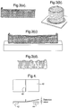
Figure 3 shows structures fabricated by means of the invention; -
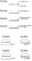
Figures 4 and5 illustrate experiments performed to demonstrate the invention, and -
Figure 6 shows test pieces fabricated in the experiments. - Referring to
Figure 1 , an apparatus for selective laser melting comprises abase plate 10 configured to receive an object or workpiece comprising a parent plate orsubstrate 12 on to which successive layers ofmaterial laser generator 24 is controlled by acomputer 26 to deliver a laser beam via anoptical fibre 28 toconventional focussing optics 30, which focus the laser beam to aspot 34 on the surface of the workpiece. A powder delivery system 32 (also known per se) delivers powder to the vicinity of thelaser spot 34 on the workpiece surface. The delivery system comprises three pipes 36 (only two shown) arranged at 120° intervals around the laser spot. - The
laser apparatus computer 26 in the X-Y plane parallel to the base plate surface, and vertically in the Z direction orthogonal to it. Thelaser spot 34 thus can be directed to any point in the working envelope in the X-Y plane, and vertically so as to accommodate workpieces of different height, and regions of different height within workpieces. As illustrated in the figure, the traverse direction is in the direction ofarrow 38, the apparatus being in the process of fabricating thelayer 22. - The
laser apparatus 24 is an Nd:YAG laser operating at a wavelength of 1064nm, and having a CW power output of 500w. Thecomputer 26 is programmed to control it either in the CW mode or a pulsed mode. - In an experiment, the apparatus was used with the laser operating in pulsed mode to produce an additive layer structure. The
substrate 12 was a plate of 316L stainless steel 100mm x 70mm x 1.5 m thick. The powdered material was 316L stainless steel. The operating parameters were as follows:Average laser power 250w (=maximum laser power x repetition rate x pulseduration) Maximum laser power 500w Pulse repetition rate 10Hz Pulse duration 50ms Laser spot size 600µm diameter Traverse rate 5mm/s Powder feed rate 5g/min - The average laser power and the powder feed rate were held constant throughout the experiment.
-
Figure 2(a) shows the pulsed laser power output. In a single traverse, the apparatus produced a fused layer of material on the substrate surface of a substantially constant thickness of approximately 40µm. - In
Figure 2(b) , there is shown a pulse modulated laser output waveform in which periodically (for 300ms in every second) the average power of the laser is increased from 250w to 500w. In other words the duty cycle of each pulse is increased from 50% to 100%. During these periods a larger quantity of material is fused by the laser onto the substrate, resulting in a thicker layer. The feed rate of the powder either is increased to cater for this increased demand, or alternatively powder is fed at the maximum rate required at any time during the traverse, and the excess powder is collected and re-used. - In the experimental apparatus, the laser pulses were nominally of triangular shape, as shown in
Figure 2 . Other pulse shapes may be used for example a square-wave shape, the power of the laser then being controlled by modulating the mark/space ratio (on/off duration) of the pulses within the pulse repetition period. -
Figures 3a to 3d show some additive layer fabrications produced by means of the invention.Figure 3a shows a fence-like structure, the side (vertical) surfaces of which exhibit a basket-weave pattern.Figure 3b shows a cylindrical structure in which the sides exhibit a helical pattern.Figure 3C shows another fence-like structure in which the side surfaces have a zig-zag or herringbone pattern. Finally,Figure 3d shows a fence patterned as woven material strung between intermediate posts. These finely-detailed patterns are achieved by means of the linear resolution obtainable in the traverse direction. For example inFigure 2 , a pulse repetition rate of 10 Hz and a traverse speed of 5mm/s implies a feed rate of 0.5mm/pulse. A traverse speed of 2mm/s yields a feed rate of 0.2mm/pulse which would enable a finer pattern to be resolved in the fabricated product. For a constant layer thickness, the power of the laser is reduced proportionally to the feed rate. Variation in width (transversely of the traverse direction) of the built-up structure can be achieved by increasing both the pulse duty cycle and the laser spot size simultaneously, so that the deposited layer is wider but not thicker. - Alternatively it can be achieved with constant laser spot size by increasing the "interaction time" of the laser. The interaction time is the time for which the laser spot is incident on an area of the workpiece, and for a given laser power and spot area is a measure of the specific power (energy per unit area per unit time applied to the workpiece) mentioned earlier. Increasing the specific power whether by increasing the interaction time or the laser power, results in a larger weld pool, which in turn allows more powder to be taken up. Thus a wider deposit of material can be achieved.
- Substantially wider formations, for example the 'posts' in
figure 3(d) can be fabricated by multiple traverses in which the laser is operated only transiently where a post is required to be built up. Patterns on the side surfaces of the structure such as inFigures 3(a) and 3(c) are achieved by delaying or advancing corresponding modulation events in successive passes. Advancing each event slightly results in a pattern rearwardly-inclined relative to the traverse direction (assuming successive passes are in the same direction). Delaying each event provides a forwardly-inclined pattern. -
Figure 4 shows a series of experiments undertaken to demonstrate distortion arising during selective laser melting, and the improvement which can be obtained with an aspect of the present invention. - In each experiment, a
sample plate 40 of 316L stainless steel 100mmx70mmx1.5mm thick was clamped at one end to asupport 42 on thebase plate 10 of thefigure 1 apparatus. The other end of the sample plate was supported by but not clamped to asupport 44. An additivelayer fabrication structure 46 comprising several superimposed layers was formed on the plate using 316L powder by means of the apparatus offigure 1 . The experiment was performed using either continuous wave laser power or pulse modulated laser power. The operating parameters were: -
Laser Power 250w Spot size 600µm diameter Traverse rate 5mm/s Powder Feed rate 5 g/min -
Average power 250w Maximum power 500w Repetition rate 10Hz Pulse duration 50ms Spot Size 600µm diameter Traverse rate 5mm/s Powder feed rate 5g/min - The experiment was performed four times, forming additive layer fabricated structures of fused material as follows:
- a) 10 layers were built to a height of 2mm using CW laser power (
Figure 5a ) - b) 50 layers were built to a height of 2mm using pulsed laser power (
Figure 5b ) - c) 5 layers were built using CW laser power followed by 25 layers using pulsed laser power to a total height of 2mm (
Figure 5c ) - d) 25 layers were built using pulsed laser power followed by 5 layers using CW laser power, to a total height of 2mm (
Figure 5d ). -
Figure 6 shows the results of the four experiments. In experiment (a), the use of CW laser power only resulted in distortion of the free edge of thesubstrate 40 by 5mm (Figure 6a ). The use of pulsed laser power only (experiment (b),Figure 6(b) ) resulted in much greater distortion of 14mm. This is thought to be due to the greater total heat input to the substrate due to the larger number of thin layers deposited using the pulsed laser technique. In contrast, building up the structure initially by the use of CW laser power in experiment (c),Figure 6c , resulted in 4.7mm distortion, approximately the same as in experiment (a). Building up the structure first by pulsed laser power followed by CW laser power (experiment (d),figure 6d ) resulted in as much distortion as did the use of pulsed laser power alone in experiment (b). - These experiments suggest that to reduce distortion it is advantageous to commence building an ALF structure using CW laser power, and then continuing with pulsed laser power to obtain the advantages of precision and surface finish discussed above. There appears to be a "threshold build height" (TBH) above which the use of pulsed laser power does not increase distortion: in the case of experiment (c), five CW layers of total thickness approximately 1 mm were sufficient, which suggests that TBH in this case was at or below that thickness. Because the conditions of each additive layer fabrication are specific to that fabrication it is necessary to determine the TBH by experiment or by reference to other similar fabrications. The guiding principle is that when the TBH is achieved, heat from the laser spot is distributed in the fabricated structure and so is not concentrated on a small area of the substrate. Compressive plastic yielding and the subsequent residual stresses and distortion thus can be avoided or reduced. Of course, residual stresses can be further reduced by annealing or other heat-treatment after the additive layer fabrication has been effected.
- Although the invention has been described with reference to the selective laser melting variant of ALF, it is applicable also to other ALF methods such as selective laser sintering, in which the heat input to the powder is sufficient to fuse individual particles together but is not sufficient to form a molten pool of material. In those variants, the amount of distortion may be reduced and the fabrication of preliminary CW layers may not be necessary.
- Furthermore, although described with reference to powdered metallic material, other fusible powdered materials may be used with operating parameters appropriate to those materials as will be known to those skilled in the art. Examples of such powders are mixtures of glass or carbon fibres or metallic particles (e.g. aluminium, titanium or steel) mixed with polyimide, polystyrene or other thermoplastic polymers, or greensand.
- Features in a built-up structure which extend significantly in a direction not perpendicular to the parent plate or substrate can be achieved by supporting the workpiece on a multi-axis manipulator or table so that its orientation relative to the (vertical) laser axis can be adjusted. For example to build up feature extending at 60° to the parent plate, the plate itself must be set at 60° to the laser axis.
- It will be appreciated that the underlying purpose of initially using CW laser power is to increase the specific power applied to the laser and hence the rate at which powdered material is fused into a layer on the substrate thereby producing a thicker layer in a single pass.
Claims (3)
- A method of fabricating an object (12, 14, 16, 18, 20, 22), the method including the steps of:a) applying heat by means of a laser beam to powdered material whereby to create a local pool of molten material so as to fuse the powdered material and create a layer (14) on a substrate (12), andb) repeating the above step as necessary to build up a stack of layers (14, 16, 18, 20, 22) one on top of the other,characterised in that the step of creating one or more said layers nearest to the substrate is carried out with higher specific power being applied to the laser (24, 28, 30) than for the step of creating the layers further from the substrate, whereby to create one or more thicker layers nearest to the substrate and thinner layers further from the substrate and thereby to reduce distortion in the substrate; and wherein
the thinner layers are formed by applying heat by means of a pulsed laser; and wherein
the step of applying higher specific power to the laser is carried out by applying heat by means of a continuous wave laser. - Fabrication apparatus for fabricating an object (12, 14, 16, 18, 20, 22), the apparatus comprising a computer (26), a base plate (10) for supporting an object onto which successive layers (14, 16, 18, 20, 22) of material may be built up, a powder delivery system (32) to deliver powder to the vicinity of a laser spot (34) on a surface of the object, a laser (24, 28, 30) adapted to deliver a laser beam to the laser spot, the laser mounted so as to be moveable under the control of the computer in the X-Y plane parallel to a base plate surface, and vertically in the Z direction orthogonal to it), characterised in that the computer is programmed to modulate the specific power applied to the laser whereby to apply a higher specific power in continuous wave mode for forming layers nearest to the substrate and a lower specific power in pulsed mode for forming layers further from the substrate.
- A computer program which when installed and operated causes the fabrication apparatus of claim 2 to perform the method of claim 1.
Priority Applications (1)
| Application Number | Priority Date | Filing Date | Title |
|---|---|---|---|
| EP10718667.8A EP2424707B2 (en) | 2009-04-28 | 2010-04-27 | Additive layer fabrication method |
Applications Claiming Priority (4)
| Application Number | Priority Date | Filing Date | Title |
|---|---|---|---|
| EP09275030A EP2246145A1 (en) | 2009-04-28 | 2009-04-28 | Additive layer fabrication method |
| GB0907226A GB0907226D0 (en) | 2009-04-28 | 2009-04-28 | Additive layer fabrication method |
| EP10718667.8A EP2424707B2 (en) | 2009-04-28 | 2010-04-27 | Additive layer fabrication method |
| PCT/GB2010/050686 WO2010125381A1 (en) | 2009-04-28 | 2010-04-27 | Additive layer fabrication method |
Publications (3)
| Publication Number | Publication Date |
|---|---|
| EP2424707A1 EP2424707A1 (en) | 2012-03-07 |
| EP2424707B1 EP2424707B1 (en) | 2018-10-31 |
| EP2424707B2 true EP2424707B2 (en) | 2021-09-29 |
Family
ID=42314761
Family Applications (1)
| Application Number | Title | Priority Date | Filing Date |
|---|---|---|---|
| EP10718667.8A Active EP2424707B2 (en) | 2009-04-28 | 2010-04-27 | Additive layer fabrication method |
Country Status (4)
| Country | Link |
|---|---|
| US (1) | US9278483B2 (en) |
| EP (1) | EP2424707B2 (en) |
| ES (1) | ES2700454T5 (en) |
| WO (1) | WO2010125381A1 (en) |
Families Citing this family (28)
| Publication number | Priority date | Publication date | Assignee | Title |
|---|---|---|---|---|
| DE102011079518A1 (en) * | 2011-07-21 | 2013-01-24 | Evonik Degussa Gmbh | Improved component properties through optimized process control in laser sintering |
| CH705662A1 (en) † | 2011-11-04 | 2013-05-15 | Alstom Technology Ltd | Process for producing articles of a solidified by gamma-prime nickel-base superalloy excretion by selective laser melting (SLM). |
| GB201204752D0 (en) * | 2012-03-19 | 2012-05-02 | Bae Systems Plc | Additive layer manufacturing |
| WO2014004704A1 (en) | 2012-06-26 | 2014-01-03 | California Institute Of Technology | Systems and methods for implementing bulk metallic glass-based macroscale gears |
| US20140342179A1 (en) | 2013-04-12 | 2014-11-20 | California Institute Of Technology | Systems and methods for shaping sheet materials that include metallic glass-based materials |
| EP2918358B1 (en) * | 2014-03-12 | 2017-06-21 | Safran Landing Systems UK Limited | Method for producing a component involving flow-forming |
| US10151377B2 (en) | 2015-03-05 | 2018-12-11 | California Institute Of Technology | Systems and methods for implementing tailored metallic glass-based strain wave gears and strain wave gear components |
| US10968527B2 (en) | 2015-11-12 | 2021-04-06 | California Institute Of Technology | Method for embedding inserts, fasteners and features into metal core truss panels |
| US10596660B2 (en) | 2015-12-15 | 2020-03-24 | Howmedica Osteonics Corp. | Porous structures produced by additive layer manufacturing |
| CN105347664B (en) * | 2015-12-15 | 2019-03-01 | 深圳市杰普特光电股份有限公司 | A kind of preform production method based on 3D printing technique |
| US11701819B2 (en) | 2016-01-28 | 2023-07-18 | Seurat Technologies, Inc. | Additive manufacturing, spatial heat treating system and method |
| US10618111B2 (en) | 2016-01-28 | 2020-04-14 | Lawrence Livermore National Security, Llc | Heat treatment to anneal residual stresses during additive manufacturing |
| US10399179B2 (en) | 2016-12-14 | 2019-09-03 | General Electric Company | Additive manufacturing systems and methods |
| KR20190119154A (en) * | 2017-03-10 | 2019-10-21 | 캘리포니아 인스티튜트 오브 테크놀로지 | Method for manufacturing strain wave gear flexplanes using metal additive manufacturing |
| EP3630395A4 (en) | 2017-05-24 | 2020-11-25 | California Institute of Technology | Hypoeutectic amorphous metal-based materials for additive manufacturing |
| WO2018223117A2 (en) | 2017-06-02 | 2018-12-06 | California Institute Of Technology | High toughness metallic glass-based composites for additive manufacturing |
| US11628517B2 (en) | 2017-06-15 | 2023-04-18 | Howmedica Osteonics Corp. | Porous structures produced by additive layer manufacturing |
| EP3479798B1 (en) | 2017-11-03 | 2023-06-21 | Howmedica Osteonics Corp. | Flexible construct for femoral reconstruction |
| AU2018385685B2 (en) * | 2017-12-15 | 2020-02-20 | Andritz Inc. | Water relief groove to prevent cavitation of opposite refiner plate |
| US11090861B2 (en) | 2018-07-26 | 2021-08-17 | General Electric Company | Systems and methods for lateral material transfer in additive manufacturing system |
| US11426818B2 (en) | 2018-08-10 | 2022-08-30 | The Research Foundation for the State University | Additive manufacturing processes and additively manufactured products |
| CN109590468B (en) * | 2018-12-07 | 2021-07-23 | 湖南大学 | Control method for manufacturing surface sticky powder of austenitic stainless steel component by laser direct additive manufacturing |
| DE102018221393A1 (en) * | 2018-12-11 | 2020-06-18 | Rhenoflex Gmbh | Powder application device and method for producing stiffening elements from powdery material |
| KR102155186B1 (en) * | 2018-12-31 | 2020-09-11 | 경북대학교 산학협력단 | Metal 3D Printing Manufacturing Method and Apparatus Using Junction Method Between Different Materials |
| US11680629B2 (en) | 2019-02-28 | 2023-06-20 | California Institute Of Technology | Low cost wave generators for metal strain wave gears and methods of manufacture thereof |
| US11859705B2 (en) | 2019-02-28 | 2024-01-02 | California Institute Of Technology | Rounded strain wave gear flexspline utilizing bulk metallic glass-based materials and methods of manufacture thereof |
| US11400613B2 (en) | 2019-03-01 | 2022-08-02 | California Institute Of Technology | Self-hammering cutting tool |
| US11591906B2 (en) | 2019-03-07 | 2023-02-28 | California Institute Of Technology | Cutting tool with porous regions |
Family Cites Families (21)
| Publication number | Priority date | Publication date | Assignee | Title |
|---|---|---|---|---|
| DE4309524C2 (en) | 1993-03-24 | 1998-05-20 | Eos Electro Optical Syst | Method of making a three-dimensional object |
| FR2707677B1 (en) * | 1993-07-13 | 1995-08-25 | Technogenia | Plate for defibering or refining paper pulp, and process for its production. |
| DE4326986C1 (en) | 1993-08-11 | 1994-12-22 | Eos Electro Optical Syst | Method and device for producing three-dimensional objects |
| US5837960A (en) | 1995-08-14 | 1998-11-17 | The Regents Of The University Of California | Laser production of articles from powders |
| JP3591147B2 (en) | 1996-07-19 | 2004-11-17 | 日産自動車株式会社 | Method of overlaying with laser beam |
| US5902538A (en) * | 1997-08-29 | 1999-05-11 | 3D Systems, Inc. | Simplified stereolithographic object formation methods of overcoming minimum recoating depth limitations |
| DE19949972C1 (en) | 1999-10-11 | 2001-02-08 | Fraunhofer Ges Forschung | Process for the manufacture of molded bodies or for the application of coatings onto workpieces comprises building up a molded body in layers or applying a coating made up of at least two individual layers |
| CA2391933A1 (en) * | 1999-11-16 | 2001-06-28 | Triton Systems, Inc. | Laser fabrication of discontinuously reinforced metal matrix composites |
| DE10042132B4 (en) | 2000-08-28 | 2012-12-13 | Cl Schutzrechtsverwaltungs Gmbh | Selective surface layer melting |
| DE10042733A1 (en) * | 2000-08-31 | 2002-03-28 | Inst Physikalische Hochtech Ev | Multicrystalline laser-crystallized silicon thin-film solar cell on a transparent substrate |
| US6518643B2 (en) * | 2001-03-23 | 2003-02-11 | International Business Machines Corporation | Tri-layer dielectric fuse cap for laser deletion |
| WO2003042895A1 (en) | 2001-11-17 | 2003-05-22 | Insstek Inc. | Method and system for real-time monitoring and controlling height of deposit by using image photographing and image processing technology in laser cladding and laser-aided direct metal manufacturing process |
| AU2003278047A1 (en) | 2002-10-31 | 2004-05-25 | Stephen F. Corbin | System and method for closed-loop control of laser cladding by powder injection |
| AU2003261497B2 (en) | 2002-11-08 | 2009-02-26 | Howmedica Osteonics Corp. | Laser-produced porous surface |
| SE524421C2 (en) | 2002-12-19 | 2004-08-10 | Arcam Ab | Apparatus and method for making a three-dimensional product |
| DE102004022385B4 (en) | 2004-05-01 | 2010-06-02 | Lim Laserinstitut Mittelsachsen Gmbh | Device for the rapid production of microbodies |
| DE102005007792B4 (en) * | 2005-02-14 | 2013-03-07 | Lim Laserinstitut Mittelsachsen Gmbh | Method and device for build-up welding of layers of particles with a particle size of less than 20 μm onto substrates |
| GB0509263D0 (en) * | 2005-05-06 | 2005-06-15 | Rolls Royce Plc | Component fabrication |
| US8728387B2 (en) | 2005-12-06 | 2014-05-20 | Howmedica Osteonics Corp. | Laser-produced porous surface |
| US20080182017A1 (en) | 2007-01-31 | 2008-07-31 | General Electric Company | Laser net shape manufacturing and repair using a medial axis toolpath deposition method |
| US8728589B2 (en) * | 2007-09-14 | 2014-05-20 | Photon Dynamics, Inc. | Laser decal transfer of electronic materials |
-
2010
- 2010-04-27 WO PCT/GB2010/050686 patent/WO2010125381A1/en active Application Filing
- 2010-04-27 US US13/318,947 patent/US9278483B2/en active Active
- 2010-04-27 EP EP10718667.8A patent/EP2424707B2/en active Active
- 2010-04-27 ES ES10718667T patent/ES2700454T5/en active Active
Also Published As
| Publication number | Publication date |
|---|---|
| EP2424707A1 (en) | 2012-03-07 |
| ES2700454T5 (en) | 2022-02-28 |
| EP2424707B1 (en) | 2018-10-31 |
| US20120132631A1 (en) | 2012-05-31 |
| US9278483B2 (en) | 2016-03-08 |
| ES2700454T3 (en) | 2019-02-15 |
| WO2010125381A1 (en) | 2010-11-04 |
Similar Documents
| Publication | Publication Date | Title |
|---|---|---|
| EP2424707B2 (en) | Additive layer fabrication method | |
| EP2424706B1 (en) | Additive layer fabrication method | |
| EP2246143A1 (en) | Additive layer fabrication method | |
| US10828720B2 (en) | Foil-based additive manufacturing system and method | |
| JP7294798B2 (en) | Systems and methods for additive structural construction techniques | |
| US10337335B2 (en) | Method for manufacturing a metallic or ceramic component by selective laser melting additive manufacturing | |
| RU2697470C2 (en) | Method and system for additive production using light beam | |
| EP2246145A1 (en) | Additive layer fabrication method | |
| US20120267345A1 (en) | Method of manufacturing a component | |
| CN102958641A (en) | Laser-based lap welding of sheet metal components using laser induced protuberances to control gap | |
| CN102328081A (en) | Method for rapidly forming three-dimensional metal parts by high-power lasers | |
| WO2020058722A1 (en) | A powder bed: additive manufacturing | |
| EP0558870B1 (en) | Free welding of metal structures casing a laser | |
| EP3741495B1 (en) | Method and system for laser additive manufacturing based on keyhole effects | |
| WO2018166555A1 (en) | Method and apparatus for wired additive manufacturing | |
| CN112404729B (en) | Wire feeding type double-beam laser additive manufacturing method | |
| WO2018089080A1 (en) | Foil-based additive manufacturing system and method | |
| EP3434396A1 (en) | Pre-fusion laser sintering for metal powder stabilization during additive manufacturing | |
| KR20210147194A (en) | Control method of slicing thickness with constant deposition and melting volume | |
| US8816239B2 (en) | Method of manufacturing a component | |
| RU2725465C2 (en) | 3d printer | |
| US20200009655A1 (en) | Processes and systems for double-pulse laser micro sintering | |
| KR20210042984A (en) | Additive manufacturing | |
| RU2688969C2 (en) | Method of hollow coatings production at gas-powder laser welding-up with radiation scanning | |
| KR20240034550A (en) | Over-deposition technique considering post-process of the curved shape for directed energy deposition process |
Legal Events
| Date | Code | Title | Description |
|---|---|---|---|
| PUAI | Public reference made under article 153(3) epc to a published international application that has entered the european phase |
Free format text: ORIGINAL CODE: 0009012 |
|
| 17P | Request for examination filed |
Effective date: 20111109 |
|
| AK | Designated contracting states |
Kind code of ref document: A1 Designated state(s): AT BE BG CH CY CZ DE DK EE ES FI FR GB GR HR HU IE IS IT LI LT LU LV MC MK MT NL NO PL PT RO SE SI SK SM TR |
|
| DAX | Request for extension of the european patent (deleted) | ||
| STAA | Information on the status of an ep patent application or granted ep patent |
Free format text: STATUS: EXAMINATION IS IN PROGRESS |
|
| 17Q | First examination report despatched |
Effective date: 20170823 |
|
| GRAP | Despatch of communication of intention to grant a patent |
Free format text: ORIGINAL CODE: EPIDOSNIGR1 |
|
| STAA | Information on the status of an ep patent application or granted ep patent |
Free format text: STATUS: GRANT OF PATENT IS INTENDED |
|
| INTG | Intention to grant announced |
Effective date: 20180612 |
|
| GRAS | Grant fee paid |
Free format text: ORIGINAL CODE: EPIDOSNIGR3 |
|
| GRAA | (expected) grant |
Free format text: ORIGINAL CODE: 0009210 |
|
| STAA | Information on the status of an ep patent application or granted ep patent |
Free format text: STATUS: THE PATENT HAS BEEN GRANTED |
|
| AK | Designated contracting states |
Kind code of ref document: B1 Designated state(s): AT BE BG CH CY CZ DE DK EE ES FI FR GB GR HR HU IE IS IT LI LT LU LV MC MK MT NL NO PL PT RO SE SI SK SM TR |
|
| REG | Reference to a national code |
Ref country code: GB Ref legal event code: FG4D Ref country code: CH Ref legal event code: EP |
|
| REG | Reference to a national code |
Ref country code: AT Ref legal event code: REF Ref document number: 1058793 Country of ref document: AT Kind code of ref document: T Effective date: 20181115 |
|
| REG | Reference to a national code |
Ref country code: IE Ref legal event code: FG4D |
|
| REG | Reference to a national code |
Ref country code: DE Ref legal event code: R096 Ref document number: 602010054739 Country of ref document: DE |
|
| REG | Reference to a national code |
Ref country code: ES Ref legal event code: FG2A Ref document number: 2700454 Country of ref document: ES Kind code of ref document: T3 Effective date: 20190215 |
|
| REG | Reference to a national code |
Ref country code: NL Ref legal event code: MP Effective date: 20181031 |
|
| REG | Reference to a national code |
Ref country code: LT Ref legal event code: MG4D |
|
| REG | Reference to a national code |
Ref country code: AT Ref legal event code: MK05 Ref document number: 1058793 Country of ref document: AT Kind code of ref document: T Effective date: 20181031 |
|
| PG25 | Lapsed in a contracting state [announced via postgrant information from national office to epo] |
Ref country code: HR Free format text: LAPSE BECAUSE OF FAILURE TO SUBMIT A TRANSLATION OF THE DESCRIPTION OR TO PAY THE FEE WITHIN THE PRESCRIBED TIME-LIMIT Effective date: 20181031 Ref country code: PL Free format text: LAPSE BECAUSE OF FAILURE TO SUBMIT A TRANSLATION OF THE DESCRIPTION OR TO PAY THE FEE WITHIN THE PRESCRIBED TIME-LIMIT Effective date: 20181031 Ref country code: LV Free format text: LAPSE BECAUSE OF FAILURE TO SUBMIT A TRANSLATION OF THE DESCRIPTION OR TO PAY THE FEE WITHIN THE PRESCRIBED TIME-LIMIT Effective date: 20181031 Ref country code: IS Free format text: LAPSE BECAUSE OF FAILURE TO SUBMIT A TRANSLATION OF THE DESCRIPTION OR TO PAY THE FEE WITHIN THE PRESCRIBED TIME-LIMIT Effective date: 20190228 Ref country code: AT Free format text: LAPSE BECAUSE OF FAILURE TO SUBMIT A TRANSLATION OF THE DESCRIPTION OR TO PAY THE FEE WITHIN THE PRESCRIBED TIME-LIMIT Effective date: 20181031 Ref country code: LT Free format text: LAPSE BECAUSE OF FAILURE TO SUBMIT A TRANSLATION OF THE DESCRIPTION OR TO PAY THE FEE WITHIN THE PRESCRIBED TIME-LIMIT Effective date: 20181031 Ref country code: FI Free format text: LAPSE BECAUSE OF FAILURE TO SUBMIT A TRANSLATION OF THE DESCRIPTION OR TO PAY THE FEE WITHIN THE PRESCRIBED TIME-LIMIT Effective date: 20181031 Ref country code: NO Free format text: LAPSE BECAUSE OF FAILURE TO SUBMIT A TRANSLATION OF THE DESCRIPTION OR TO PAY THE FEE WITHIN THE PRESCRIBED TIME-LIMIT Effective date: 20190131 Ref country code: BG Free format text: LAPSE BECAUSE OF FAILURE TO SUBMIT A TRANSLATION OF THE DESCRIPTION OR TO PAY THE FEE WITHIN THE PRESCRIBED TIME-LIMIT Effective date: 20190131 |
|
| PG25 | Lapsed in a contracting state [announced via postgrant information from national office to epo] |
Ref country code: PT Free format text: LAPSE BECAUSE OF FAILURE TO SUBMIT A TRANSLATION OF THE DESCRIPTION OR TO PAY THE FEE WITHIN THE PRESCRIBED TIME-LIMIT Effective date: 20190301 Ref country code: NL Free format text: LAPSE BECAUSE OF FAILURE TO SUBMIT A TRANSLATION OF THE DESCRIPTION OR TO PAY THE FEE WITHIN THE PRESCRIBED TIME-LIMIT Effective date: 20181031 Ref country code: GR Free format text: LAPSE BECAUSE OF FAILURE TO SUBMIT A TRANSLATION OF THE DESCRIPTION OR TO PAY THE FEE WITHIN THE PRESCRIBED TIME-LIMIT Effective date: 20190201 Ref country code: SE Free format text: LAPSE BECAUSE OF FAILURE TO SUBMIT A TRANSLATION OF THE DESCRIPTION OR TO PAY THE FEE WITHIN THE PRESCRIBED TIME-LIMIT Effective date: 20181031 |
|
| REG | Reference to a national code |
Ref country code: DE Ref legal event code: R026 Ref document number: 602010054739 Country of ref document: DE |
|
| PLBI | Opposition filed |
Free format text: ORIGINAL CODE: 0009260 |
|
| 26 | Opposition filed |
Opponent name: SIEMENS AKTIENGESELLSCHAFT Effective date: 20190619 |
|
| PG25 | Lapsed in a contracting state [announced via postgrant information from national office to epo] |
Ref country code: DK Free format text: LAPSE BECAUSE OF FAILURE TO SUBMIT A TRANSLATION OF THE DESCRIPTION OR TO PAY THE FEE WITHIN THE PRESCRIBED TIME-LIMIT Effective date: 20181031 Ref country code: CZ Free format text: LAPSE BECAUSE OF FAILURE TO SUBMIT A TRANSLATION OF THE DESCRIPTION OR TO PAY THE FEE WITHIN THE PRESCRIBED TIME-LIMIT Effective date: 20181031 |
|
| PLAF | Information modified related to communication of a notice of opposition and request to file observations + time limit |
Free format text: ORIGINAL CODE: EPIDOSCOBS2 |
|
| PLAX | Notice of opposition and request to file observation + time limit sent |
Free format text: ORIGINAL CODE: EPIDOSNOBS2 |
|
| PG25 | Lapsed in a contracting state [announced via postgrant information from national office to epo] |
Ref country code: RO Free format text: LAPSE BECAUSE OF FAILURE TO SUBMIT A TRANSLATION OF THE DESCRIPTION OR TO PAY THE FEE WITHIN THE PRESCRIBED TIME-LIMIT Effective date: 20181031 Ref country code: SK Free format text: LAPSE BECAUSE OF FAILURE TO SUBMIT A TRANSLATION OF THE DESCRIPTION OR TO PAY THE FEE WITHIN THE PRESCRIBED TIME-LIMIT Effective date: 20181031 Ref country code: EE Free format text: LAPSE BECAUSE OF FAILURE TO SUBMIT A TRANSLATION OF THE DESCRIPTION OR TO PAY THE FEE WITHIN THE PRESCRIBED TIME-LIMIT Effective date: 20181031 Ref country code: SM Free format text: LAPSE BECAUSE OF FAILURE TO SUBMIT A TRANSLATION OF THE DESCRIPTION OR TO PAY THE FEE WITHIN THE PRESCRIBED TIME-LIMIT Effective date: 20181031 |
|
| PG25 | Lapsed in a contracting state [announced via postgrant information from national office to epo] |
Ref country code: SI Free format text: LAPSE BECAUSE OF FAILURE TO SUBMIT A TRANSLATION OF THE DESCRIPTION OR TO PAY THE FEE WITHIN THE PRESCRIBED TIME-LIMIT Effective date: 20181031 |
|
| REG | Reference to a national code |
Ref country code: CH Ref legal event code: PL |
|
| REG | Reference to a national code |
Ref country code: BE Ref legal event code: MM Effective date: 20190430 |
|
| PLBB | Reply of patent proprietor to notice(s) of opposition received |
Free format text: ORIGINAL CODE: EPIDOSNOBS3 |
|
| PG25 | Lapsed in a contracting state [announced via postgrant information from national office to epo] |
Ref country code: LU Free format text: LAPSE BECAUSE OF NON-PAYMENT OF DUE FEES Effective date: 20190427 Ref country code: MC Free format text: LAPSE BECAUSE OF FAILURE TO SUBMIT A TRANSLATION OF THE DESCRIPTION OR TO PAY THE FEE WITHIN THE PRESCRIBED TIME-LIMIT Effective date: 20181031 |
|
| PG25 | Lapsed in a contracting state [announced via postgrant information from national office to epo] |
Ref country code: LI Free format text: LAPSE BECAUSE OF NON-PAYMENT OF DUE FEES Effective date: 20190430 Ref country code: CH Free format text: LAPSE BECAUSE OF NON-PAYMENT OF DUE FEES Effective date: 20190430 |
|
| PG25 | Lapsed in a contracting state [announced via postgrant information from national office to epo] |
Ref country code: BE Free format text: LAPSE BECAUSE OF NON-PAYMENT OF DUE FEES Effective date: 20190430 |
|
| PG25 | Lapsed in a contracting state [announced via postgrant information from national office to epo] |
Ref country code: TR Free format text: LAPSE BECAUSE OF FAILURE TO SUBMIT A TRANSLATION OF THE DESCRIPTION OR TO PAY THE FEE WITHIN THE PRESCRIBED TIME-LIMIT Effective date: 20181031 |
|
| PG25 | Lapsed in a contracting state [announced via postgrant information from national office to epo] |
Ref country code: IE Free format text: LAPSE BECAUSE OF NON-PAYMENT OF DUE FEES Effective date: 20190427 |
|
| PLAB | Opposition data, opponent's data or that of the opponent's representative modified |
Free format text: ORIGINAL CODE: 0009299OPPO |
|
| R26 | Opposition filed (corrected) |
Opponent name: SIEMENS AKTIENGESELLSCHAFT Effective date: 20190619 |
|
| PG25 | Lapsed in a contracting state [announced via postgrant information from national office to epo] |
Ref country code: CY Free format text: LAPSE BECAUSE OF FAILURE TO SUBMIT A TRANSLATION OF THE DESCRIPTION OR TO PAY THE FEE WITHIN THE PRESCRIBED TIME-LIMIT Effective date: 20181031 |
|
| PG25 | Lapsed in a contracting state [announced via postgrant information from national office to epo] |
Ref country code: HU Free format text: LAPSE BECAUSE OF FAILURE TO SUBMIT A TRANSLATION OF THE DESCRIPTION OR TO PAY THE FEE WITHIN THE PRESCRIBED TIME-LIMIT; INVALID AB INITIO Effective date: 20100427 Ref country code: MT Free format text: LAPSE BECAUSE OF FAILURE TO SUBMIT A TRANSLATION OF THE DESCRIPTION OR TO PAY THE FEE WITHIN THE PRESCRIBED TIME-LIMIT Effective date: 20181031 |
|
| PUAH | Patent maintained in amended form |
Free format text: ORIGINAL CODE: 0009272 |
|
| STAA | Information on the status of an ep patent application or granted ep patent |
Free format text: STATUS: PATENT MAINTAINED AS AMENDED |
|
| 27A | Patent maintained in amended form |
Effective date: 20210929 |
|
| AK | Designated contracting states |
Kind code of ref document: B2 Designated state(s): AT BE BG CH CY CZ DE DK EE ES FI FR GB GR HR HU IE IS IT LI LT LU LV MC MK MT NL NO PL PT RO SE SI SK SM TR |
|
| REG | Reference to a national code |
Ref country code: DE Ref legal event code: R102 Ref document number: 602010054739 Country of ref document: DE |
|
| REG | Reference to a national code |
Ref country code: ES Ref legal event code: DC2A Ref document number: 2700454 Country of ref document: ES Kind code of ref document: T5 Effective date: 20220228 |
|
| PG25 | Lapsed in a contracting state [announced via postgrant information from national office to epo] |
Ref country code: MK Free format text: LAPSE BECAUSE OF FAILURE TO SUBMIT A TRANSLATION OF THE DESCRIPTION OR TO PAY THE FEE WITHIN THE PRESCRIBED TIME-LIMIT Effective date: 20181031 |
|
| PGFP | Annual fee paid to national office [announced via postgrant information from national office to epo] |
Ref country code: FR Payment date: 20230321 Year of fee payment: 14 |
|
| PGFP | Annual fee paid to national office [announced via postgrant information from national office to epo] |
Ref country code: IT Payment date: 20230322 Year of fee payment: 14 Ref country code: GB Payment date: 20230321 Year of fee payment: 14 |
|
| PGFP | Annual fee paid to national office [announced via postgrant information from national office to epo] |
Ref country code: ES Payment date: 20230502 Year of fee payment: 14 Ref country code: DE Payment date: 20230321 Year of fee payment: 14 |