EP3740635B1 - A hinge cover and vehicle - Google Patents
A hinge cover and vehicle Download PDFInfo
- Publication number
- EP3740635B1 EP3740635B1 EP19700542.4A EP19700542A EP3740635B1 EP 3740635 B1 EP3740635 B1 EP 3740635B1 EP 19700542 A EP19700542 A EP 19700542A EP 3740635 B1 EP3740635 B1 EP 3740635B1
- Authority
- EP
- European Patent Office
- Prior art keywords
- hinge
- cover member
- hinge arm
- arm
- shaped portion
- Prior art date
- Legal status (The legal status is an assumption and is not a legal conclusion. Google has not performed a legal analysis and makes no representation as to the accuracy of the status listed.)
- Active
Links
Images


Classifications
-
- B—PERFORMING OPERATIONS; TRANSPORTING
- B60—VEHICLES IN GENERAL
- B60R—VEHICLES, VEHICLE FITTINGS, OR VEHICLE PARTS, NOT OTHERWISE PROVIDED FOR
- B60R13/00—Elements for body-finishing, identifying, or decorating; Arrangements or adaptations for advertising purposes
-
- E—FIXED CONSTRUCTIONS
- E05—LOCKS; KEYS; WINDOW OR DOOR FITTINGS; SAFES
- E05D—HINGES OR SUSPENSION DEVICES FOR DOORS, WINDOWS OR WINGS
- E05D11/00—Additional features or accessories of hinges
- E05D11/0054—Covers, e.g. for protection
-
- E—FIXED CONSTRUCTIONS
- E05—LOCKS; KEYS; WINDOW OR DOOR FITTINGS; SAFES
- E05D—HINGES OR SUSPENSION DEVICES FOR DOORS, WINDOWS OR WINGS
- E05D5/00—Construction of single parts, e.g. the parts for attachment
- E05D5/02—Parts for attachment, e.g. flaps
- E05D5/06—Bent flaps
- E05D5/062—Bent flaps specially adapted for vehicles
-
- E—FIXED CONSTRUCTIONS
- E05—LOCKS; KEYS; WINDOW OR DOOR FITTINGS; SAFES
- E05D—HINGES OR SUSPENSION DEVICES FOR DOORS, WINDOWS OR WINGS
- E05D5/00—Construction of single parts, e.g. the parts for attachment
- E05D5/02—Parts for attachment, e.g. flaps
- E05D5/06—Bent flaps
- E05D2005/067—Bent flaps gooseneck shaped
-
- E—FIXED CONSTRUCTIONS
- E05—LOCKS; KEYS; WINDOW OR DOOR FITTINGS; SAFES
- E05Y—INDEXING SCHEME ASSOCIATED WITH SUBCLASSES E05D AND E05F, RELATING TO CONSTRUCTION ELEMENTS, ELECTRIC CONTROL, POWER SUPPLY, POWER SIGNAL OR TRANSMISSION, USER INTERFACES, MOUNTING OR COUPLING, DETAILS, ACCESSORIES, AUXILIARY OPERATIONS NOT OTHERWISE PROVIDED FOR, APPLICATION THEREOF
- E05Y2201/00—Constructional elements; Accessories therefor
- E05Y2201/10—Covers; Housings
- E05Y2201/11—Covers
Definitions
- the present invention relates to hinge covers, more particularly but not exclusively, the present invention relates to hinge covers for hinges with an elongate hinge arm used to attach a closure to a vehicle body.
- the invention also relates to a vehicle having such a cover mounted to a hinge arm
- Hinges are used on vehicles to attach moveable closures, such as doors, bonnets, tailgates, and boot lids, etc., to the vehicle body.
- Hinges having elongate hinge arms are often used mount a boot lid to the body for example.
- Such hinges are often referred to as swan neck hinges due to the shape of the hinge arm and are used because they assist in supporting the weight of the boot lid upon opening or closing and help in guiding the boot lid through both the opening and closing movements.
- covers In order to improve the aesthetics of a vehicle, it is known to attach covers to conceal components that may be deemed unsightly, or deemed to create an unfinished appearance. It is known in particular to attach covers to the elongate arms of swan neck type hinges in order to conceal the hinge arm and any attached cable or harness.
- the known hinge covers usually comprise visible fixings such as buckles, belts, clips or straps in order to securely retain the hinge covers in place. Such visible fixings can be aesthetically unsatisfactory.
- the known covers for swan neck type hinges generally comprise an elongate three sided channel section which goes over the arm to cover it on the three most exposed sides. Whilst this covers the majority of the hinge arm, the arm, and any attached cable or harness, remains visible along the exposed fourth side reducing the aesthetic quality. It is also known to provide a housing portion at the closure end of the channel shaped portion which encapsulates the hinge mounting on the closure. Where a trim panel is attached to the interior surface of the closure, the trim panel and the housing portion are aligned to provide a neat finish. However, subsequent adjustment of the closure causes it to move relative to the hinge arm on which the cover is mounted and can result in the housing portion moving out of alignment with the trim panel, leading to excessive gapping between them.
- JP2016/022782 describes a trunk lid hinge structure connected to a trunk lid equipped with a pipe-like hinge cover for covering a long hinge to which a harness for an electrical component is attached.
- US2015/183382 describes a cover for a hinge arm connecting a vehicle trunk lid to the vehicle.
- the cover includes an inside surface, a first end and a second end, a rib and a flange portion.
- the rib is located along the inside surface of the cover at the first end.
- the flange portion extends generally orthogonally from the first end of the cover. The rib and flange portion help to secure the cover and increase its effectiveness at covering other components of the vehicle.
- JP3260114 describes a wire harness cover which is temporarily fixed to a hinge arm using engaging protrusions which extend into holes in the hinge arm. Lids are used to permanently fix the cover to the hinge arm.
- EP2085550 describes a hinge structure for a vehicle open/close body, in which a long hinge member supporting the open/close body is rotatably disposed in an opening portion of a vehicle body and the hinge member rotates according to an opening and closing motion of the open/close body, wherein a cover member for covering the hinge member is disposed in the hinge member; and wherein a shape of an outer periphery surface of the cover member facing a corner portion of the opening portion is formed in a shape following a shape of the corner portion.
- a hinge cover for a hinge having an elongate hinge arm, wherein any fixings used to secure the cover to the hinge arm are not visible when the cover is mounted.
- a hinge cover for a hinge having an elongate arm which is able to form a flexible connection with a trim panel on an associated closure in order to prevent gapping upon relative movement between the closure and the hinge arm.
- a hinge cover member for use with a swan neck type hinge for attaching a closure to a vehicle body, the hinge having a mounting structure at one end of a hinge arm for attaching the hinge arm to the closure, the hinge cover member comprising an elongate channel shaped portion for receiving the hinge arm and a housing portion at one end of the elongate channel shaped portion configured to overlie part of a surface of the closure about the mounting structure and wherein the housing portion defines at least one formation for attaching an edge of a trim panel mounted to the closure to the housing portion.
- the at least one formation may be a clip formation for gripping said edge of the trim panel.
- the at least one clip formation may define a slot or recess along at least part of an edge of the housing portion into which an edge region of the trim panel is inserted in use.
- the height of the slot or recess may be adjusted relative to the corresponding trim panel edge that is to be received.
- the slot or recess may further be adjusted depending on the clamping force that is to be applied to the trim panel edge.
- the housing portion may be integrally formed with the channel shaped portion, or may be a separate component adapted to form a connection with the channel shaped portion.
- the housing portion may entirely conceal, or conceal a significant proportion of, the mounting structure in use.
- the elongate channel shaped portion defines a pair of spaced side walls interconnected at one end by a base region, the elongate channel portion being resiliently deformable such that the side walls can be biased apart from a rest position, a plurality of locking projections being provided on the inner surface of the elongate channel shaped portion for engagement with corresponding locking formations on the hinge arm to secure the cover member to the hinge arm. Said plurality of locking projections may be provided on the inner surface of at least one of the side walls.
- the side walls of the elongate channel shaped portion may be configured to be biased apart from the rest position to allow the first cover member to be mounted to the hinge arm in use.
- a plurality of locating ribs are spaced apart along the inner surface of the elongate channel shaped portion for engagement with an outer surface of the hinge arm.
- the plurality of locating ribs comprise locating ribs on an inner surface of one of the side walls for engagement with a first side of the hinge arm, a plurality of clamping formations projecting from the inner surface of the base region in spaced relation said one of the side walls, the clamping formations configured to engage a second side of the hinge arm opposite the first side such that in use, the hinge arm is clamped between the clamping formations and the locating ribs on said one side wall of the elongate channel shaped portion.
- the hinge cover member may be a first hinge cover member forming part of a hinge cover assembly together with a second hinge cover member, the first and second cover members being mountable about the hinge arm and configured so as to completely encircle the hinge arm over at least part of its length in use.
- a vehicle having a body and a closure mounted to the body by a swan neck type hinge, the hinge having an elongate hinge arm attached to the closure at one end by a mounting structure, wherein a hinge cover member in accordance with the first aspect of the invention is mounted to the hinge arm.
- a trim panel may be mounted to the closure and an edge of the trim panel attached to the housing portion by said formation. Where said formation is a clip formation, an edge of the trim panel may be clamped in the clip formation.
- the trim panel may have a live hinge proximal said edge about which the trim panel is able to flex. This may accommodate at least a limited degree of relative movement between the housing portion and the closure without the edge region of the trim panel disconnecting from said clip formation.
- the arrangement may be configured such that during adjustment of the position of the closure relative to the hinge, the edge region of the trim panel is constrained to move with the hinge cover.
- the housing portion may have a first section extending generally in a first plane for overlaying an inner face of the closure to which the second mounting structure is attached and a second section extending generally in a second plane perpendicular to the first plane, the clip formation being provided along an edge of the second section.
- the hinge arm may define corresponding locking formations in the form of locking apertures in which the locking projections engage to secure the hinge cover member to the hinge arm.
- the locking apertures may be defined in a side region of the hinge arm.
- the hinge cover comprises locating ribs on an inner surface of one of the side walls for engagement with a first side of the hinge arm and a plurality of clamping formations projecting from the inner surface of the base region in spaced relation said one of the side walls
- the hinge arm may be clamped between the locating ribs on said one of the side walls of the elongate channel shaped portion of the hinge cover member and the clamping formations.
- the spacing between the side walls of the elongate channel shaped portion of the hinge cover member may be greater than the width of the hinge arm.
- the closure may be a boot lid.
- the hinge cover assembly 10 is adapted for use with a swan neck hinge 12 as illustrated in Figures 3 and 4 .
- Hinges of this type are commonly used for mounting a movable closure to a vehicle body.
- the hinge is used to mount a boot lid 13 to the body of a vehicle.
- the invention is not limited to use with hinges for mounting boot lids but can be adapted for use with hinges for mounting other types of closure to a vehicle or indeed non-vehicular applications.
- the hinge 12 has an elongate hinge arm 14 and includes a first mounting structure 16 at one end for attaching the hinge arm 14 to the body of a vehicle (not shown) and a second mounting structure 18 at the other end for attaching the hinge arm 14 to the boot lid 13.
- the hinge arm is pivotally connected to each of the mounting structures 16, 18 in a known manner and may be adjustably connected to at least the first mounting structure 16.
- the hinge cover assembly 10 includes a first cover member 20 and a second cover member 22.
- the first cover member 20 has an elongate channel shaped portion 24 having a pair of opposed side walls 26, 28 interconnected at one end by a base region or wall 30.
- the channel shaped portion 24 is mounted over the elongate arm 14 of the swan neck hinge 12 to encapsulate the arm about three sides over part of its length.
- the hinge arm 14 is curved in the longitudinal direction and the elongate channel shaped portion 24 is correspondingly curved to form a close fit over the hinge arm 12.
- At one end of the channel shaped portion 24 is a housing portion or flange 32. In use, the housing portion 32 overlies part of the boot lid 13 so as to encase at least part of the second mounting structure 28.
- the second cover member 22 is releasably attachable to the channel shaped portion 24 of the first cover member so as to extend between the free ends of the side walls 26, 28 in opposed relation to the base region 30.
- the second cover member 22 is an elongate U shaped member having a base 22A and a pair of depending flanges 22B.
- the base 22A is substantially planar in the lateral direction but curves in the longitudinal direction to conform to the curvature of the channel shaped portion 24.
- the flanges 22B are a close fit between side walls 26, 28 of the first cover member 20.
- At least the channel shaped portion 24 of the first cover member 20 is resiliently flexible so that the side walls 26, 28 can be moved apart from a rest position to enable fitment over the hinge arm 14 and for mounting of the second cover member 22.
- the arrangement is such that the second cover member 22 is a tight fit between the side walls 26, 28 of the first cover member when they are in the rest position.
- Male engagement members or lugs 34 are spaced apart along the inner surface of each side wall 26, 28 of first cover member proximal their free ends and corresponding female engagement members or apertures 36 are provided in each of the flanges 22B of the second cover member. The male engagement members 34 are received in the apertures 36 to lock the second cover member 22 to the first cover member 20 when assembled.
- first cover member 20 is mounted to the hinge arm 14 as illustrated in Figures 3 , 3A and 3B so that it extends about the hinge arm on the three most exposed sides of the arm.
- the second cover member 22 is then mounted to the first cover member 22, as can be seen best in Figures 2 and 3A , to cover the remaining side of the hinge arm 14 so that the arm is fully enclosed or encircled over at least part of its length.
- the hinge cover assembly 10 encircles the hinge arm 14 of that part of its length which is generally exposed to view when the boot lid is open.
- FIG. 1 , 3A and 3B An embodiment for mounting of the first cover member 20 to the hinge arm 14 is best seen in Figures 1 , 3A and 3B .
- the spacing between the side walls 26, 28 of the channel shaped portion 24 is larger than the width of the hinge arm 14.
- a number of locating ribs 40A, 40B project inwardly from the inner surface of a first one of the side walls 26.
- the ribs 40A, 40B extend from the base outwardly towards the free end of the first side wall 26 over part of its height and are spaced apart along the length of the channel shaped portion 24.
- the locating ribs 40A, 40B are arranged to contact the hinge arm 14 on one side.
- ribs 40A only extend up the first side wall whilst others 40B also extend laterally across the inner surface of the base region 30 and up part of the second side wall 28.
- the ribs 40A, 40B each define a slot 40C at their upper end or ends into which the corresponding flange 22B of the second cover member 22 is received.
- a clamping formation 40D which projects inwardly from the base region 30 in spaced relation to the first side wall 26.
- the clamping formations 40D define an abutment surface 42 which opposes the first side wall 26 and which in use contacts the hinge arm 14 on the opposite side from the ribs 40A, 40B so that the hinge arm is clamped between the ribs 40A, 40B on the first side wall 26 and the clamping formations 40D. This locates the first cover member 20 relative to the hinge arm 14.
- a longitudinal channel 44 is defined between the hinge arm 14 and the second side wall 28 through which cables or harnesses or other components can be routed.
- a number of locking projections 46 extend inwardly (laterally) from the inner surface of the first side wall 26.
- the locking projections 46 in this embodiment are in the form of pegs or pins which extend inwardly by a greater distance then the locating ribs 40A, 40B.
- the pegs or pins 46 may be cylindrical or cross shaped in lateral cross-section.
- Each locking projection 46 is received in a corresponding locking aperture 48 defined in a side wall 50 of the hinge arm proximal the first side wall 26.
- the first side wall 26 is flexed outwardly away from the second side wall 28 and the clamping formations 40D to enable the hinge arm to be located between the fist side wall 26 and the clamping formations 40D and to enable the locking projections 46 to slide up the side 50 of the hinge arm 14 to engage in their respective locking apertures 48.
- the locking projections 46 have a chamfered upper edge 52 which engages the hinge arm to force the first side wall 26 outwardly when the first cover member is pressed on to the hinge arm.
- the natural resilience of the material biases the first side wall 26 back to its rest position in which the hinge arm 14 is clamped between the locating ribs 40A, 40B on the first side wall 26 and the clamping formations 40D and the locking projections 46 are firmly located in the locking apertures 48.
- the first hinge cover member 20 is arranged so that once fitted, it is a tight fit on the hinge arm 14. Any cables, harnesses or other components that are to be routed along the longitudinal channel 44 can be arranged in position and fixed using ties as required.
- the second cover member 22 is then pressed into position between the free ends of the first and second side walls 26, 28 of the first cover member.
- the first and second side walls 26, 28 may flex apart slightly to enable the second cover member 22 to be pressed into place.
- the hinge arm 14 is completely encircled by the hinge cover assembly on all sides so that no part of the hinge arm or any associated cables, harness or other components routed along the hinge are visible over at least part of the length of the hinge arm. This provides for a particularly neat appearance.
- all the fittings for securing the first cover member 20 to hinge arm are located internally of the channel shaped portion 24, there no externally visible fixings which further provides for a neat and aesthetically pleasing finish.
- the first and second cover members 20, 22 can be made of any suitable material but are conveniently moulded from a polymeric material selected to provide the desired mechanical properties and aesthetic appearance.
- first and second cover members may have corresponding male and female connectors which can be engaged, say with a snap fit, to fix the second cover member 22 to the first cover member 20. It is preferable though that any such connectors should not be visible from the outside once the cover members are assembled together.
- a hinge cover comprising only a first cover member 20 may still be advantageous as it will enclose the hinge arm on the three most exposed sides but without any fixings that are visible once the cover member is mounted to the hinge arm.
- the first hinge cover member 20 if used on its own may be modified to omit the mounting slots 40C and may be modified so that the second side wall 28 is located closer to hinge arm 14.
- the second side wall 28 could be adapted to contact the hinge arm 14 on the opposite side from the first side wall or be provided with locating ribs similar to the ribs 40A, 40B on the first side wall omitting the clamping formations 40D.
- FIGS 5 to 8 illustrate another aspect of the invention.
- the housing portion or flange 32 at the closure end of the elongate channel shaped portion 24 of the first cover member is arranged to overlie part of the inner face 54 of the boot lid 13 to which the hinge arm 14 is attached by the second hinge mounting structure 18.
- the housing portion 32 thus covers the second hinge mounting structure 18 where it locates on the boot lid so that the mounting structure is not visible.
- the housing portion is profiled to interface with a trim panel 56 mounted to the inner surface of the boot lid 13 and to conform to the shape of the boot lid to provide a neat finish.
- the trim panel 56 may comprise a section of carpet or other fabric, for example.
- the second mounting structure 18 is attached close to a lower edge 58 of the boot lid and close to one side edge 60.
- the housing portion 32 has a first section 62 which extends generally in a first plane overlying an inner face 54 of the boot lid 13 where the second mounting structure 18 is attached and a second section 64 which overlies part of the lower edge 58 of the boot lid and which extends generally in a second plane perpendicular to the first plane.
- the position of the second mounting structure 18 relative to the boot lid 13 is adjustable, typically in a direction perpendicular to the first plane as indicated by arrows 66. Since the hinge cover assembly 10 is mounted to the hinge arm 14 and the trim panel 56 is mounted to the boot lid, adjusting the position of the second mounting structure 18 will result in relative movement between the housing portion 32 and the trim panel 56 which can affect the neatness of the finish. A particular issue is that relative movement between the second mounting structure 18 and the boot lid in a direction parallel to the first plane will result in the second section 64 of the housing portion 32 moving towards or away from the lower edge 58 of the boot lid which can result in a gap appearing between the housing portion 32 and the trim panel 56.
- the housing portion 32 defines a clip formation 70 which grips an edge region 72 of the trim panel 56 and the trim panel has a live hinge 74 which extends generally parallel to the respective side edge 68 of the second section.
- the edge region 72 of the trim panel is constrained to move with the housing portion 32 if the position of the second mounting structure 18 on the boot lid 13 is adjusted, as is illustrated by the dashed lines at 76 in Figure 8 . This prevents gaps appearing between the housing portion 32 and the trim panel 56.
- the clip formation 70 comprises a C-section slot or recess in which the edge region 72 of the trim panel is inserted, the C-section being configured to clamp the edge region 72.
- the hinge cover comprises a first cover member 20 only or where the hinge cover is an assembly comprising first and second cover members 20, 22 as described above.
Landscapes
- Engineering & Computer Science (AREA)
- Mechanical Engineering (AREA)
- Superstructure Of Vehicle (AREA)
Description
- The present invention relates to hinge covers, more particularly but not exclusively, the present invention relates to hinge covers for hinges with an elongate hinge arm used to attach a closure to a vehicle body. The invention also relates to a vehicle having such a cover mounted to a hinge arm
- Hinges are used on vehicles to attach moveable closures, such as doors, bonnets, tailgates, and boot lids, etc., to the vehicle body. Hinges having elongate hinge arms are often used mount a boot lid to the body for example. Such hinges are often referred to as swan neck hinges due to the shape of the hinge arm and are used because they assist in supporting the weight of the boot lid upon opening or closing and help in guiding the boot lid through both the opening and closing movements.
- Due to the structural requirements, it is not viable to position swan neck hinges in a location that conceals them from view when the respective closure is open. Electrical cables or harnesses which must pass from the body into the closure are often routed along the hinge arm and so will also be exposed when the closure is open.
- In order to improve the aesthetics of a vehicle, it is known to attach covers to conceal components that may be deemed unsightly, or deemed to create an unfinished appearance. It is known in particular to attach covers to the elongate arms of swan neck type hinges in order to conceal the hinge arm and any attached cable or harness. The known hinge covers usually comprise visible fixings such as buckles, belts, clips or straps in order to securely retain the hinge covers in place. Such visible fixings can be aesthetically unsatisfactory.
- The known covers for swan neck type hinges generally comprise an elongate three sided channel section which goes over the arm to cover it on the three most exposed sides. Whilst this covers the majority of the hinge arm, the arm, and any attached cable or harness, remains visible along the exposed fourth side reducing the aesthetic quality. It is also known to provide a housing portion at the closure end of the channel shaped portion which encapsulates the hinge mounting on the closure. Where a trim panel is attached to the interior surface of the closure, the trim panel and the housing portion are aligned to provide a neat finish. However, subsequent adjustment of the closure causes it to move relative to the hinge arm on which the cover is mounted and can result in the housing portion moving out of alignment with the trim panel, leading to excessive gapping between them.
-
JP2016/022782 -
US2015/183382 describes a cover for a hinge arm connecting a vehicle trunk lid to the vehicle. The cover includes an inside surface, a first end and a second end, a rib and a flange portion. The rib is located along the inside surface of the cover at the first end. Opposite the rib, the flange portion extends generally orthogonally from the first end of the cover. The rib and flange portion help to secure the cover and increase its effectiveness at covering other components of the vehicle. -
JP3260114 -
EP2085550 describes a hinge structure for a vehicle open/close body, in which a long hinge member supporting the open/close body is rotatably disposed in an opening portion of a vehicle body and the hinge member rotates according to an opening and closing motion of the open/close body, wherein a cover member for covering the hinge member is disposed in the hinge member; and wherein a shape of an outer periphery surface of the cover member facing a corner portion of the opening portion is formed in a shape following a shape of the corner portion. - It would be advantageous to provide a hinge cover assembly that at least partially mitigates one or more drawbacks associated with the known hinge covers.
- In particular, it would be beneficial to provide a hinge cover for a hinge having an elongate hinge arm, wherein any fixings used to secure the cover to the hinge arm are not visible when the cover is mounted.
- It would also be advantageous to provide a hinge cover for a hinge having an elongate arm suitable for concealing a larger proportion of a hinge arm than current covers achieve.
- It would also be beneficial to provide a hinge cover for a hinge having an elongate arm which is able to form a flexible connection with a trim panel on an associated closure in order to prevent gapping upon relative movement between the closure and the hinge arm.
- According to a first aspect of the invention, there is provided a hinge cover member for use with a swan neck type hinge for attaching a closure to a vehicle body, the hinge having a mounting structure at one end of a hinge arm for attaching the hinge arm to the closure, the hinge cover member comprising an elongate channel shaped portion for receiving the hinge arm and a housing portion at one end of the elongate channel shaped portion configured to overlie part of a surface of the closure about the mounting structure and wherein the housing portion defines at least one formation for attaching an edge of a trim panel mounted to the closure to the housing portion.
- The at least one formation may be a clip formation for gripping said edge of the trim panel. The at least one clip formation may define a slot or recess along at least part of an edge of the housing portion into which an edge region of the trim panel is inserted in use. The height of the slot or recess may be adjusted relative to the corresponding trim panel edge that is to be received. The slot or recess may further be adjusted depending on the clamping force that is to be applied to the trim panel edge.
- The housing portion may be integrally formed with the channel shaped portion, or may be a separate component adapted to form a connection with the channel shaped portion. The housing portion may entirely conceal, or conceal a significant proportion of, the mounting structure in use.
- In an embodiment, the elongate channel shaped portion defines a pair of spaced side walls interconnected at one end by a base region, the elongate channel portion being resiliently deformable such that the side walls can be biased apart from a rest position, a plurality of locking projections being provided on the inner surface of the elongate channel shaped portion for engagement with corresponding locking formations on the hinge arm to secure the cover member to the hinge arm. Said plurality of locking projections may be provided on the inner surface of at least one of the side walls. The side walls of the elongate channel shaped portion may be configured to be biased apart from the rest position to allow the first cover member to be mounted to the hinge arm in use.
- In an embodiment, a plurality of locating ribs are spaced apart along the inner surface of the elongate channel shaped portion for engagement with an outer surface of the hinge arm. In an embodiment the plurality of locating ribs comprise locating ribs on an inner surface of one of the side walls for engagement with a first side of the hinge arm, a plurality of clamping formations projecting from the inner surface of the base region in spaced relation said one of the side walls, the clamping formations configured to engage a second side of the hinge arm opposite the first side such that in use, the hinge arm is clamped between the clamping formations and the locating ribs on said one side wall of the elongate channel shaped portion.
- The hinge cover member may be a first hinge cover member forming part of a hinge cover assembly together with a second hinge cover member, the first and second cover members being mountable about the hinge arm and configured so as to completely encircle the hinge arm over at least part of its length in use.
- In accordance with a second aspect of the invention, there is provided a vehicle having a body and a closure mounted to the body by a swan neck type hinge, the hinge having an elongate hinge arm attached to the closure at one end by a mounting structure, wherein a hinge cover member in accordance with the first aspect of the invention is mounted to the hinge arm.
- A trim panel may be mounted to the closure and an edge of the trim panel attached to the housing portion by said formation. Where said formation is a clip formation, an edge of the trim panel may be clamped in the clip formation. The trim panel may have a live hinge proximal said edge about which the trim panel is able to flex. This may accommodate at least a limited degree of relative movement between the housing portion and the closure without the edge region of the trim panel disconnecting from said clip formation. The arrangement may be configured such that during adjustment of the position of the closure relative to the hinge, the edge region of the trim panel is constrained to move with the hinge cover. The housing portion may have a first section extending generally in a first plane for overlaying an inner face of the closure to which the second mounting structure is attached and a second section extending generally in a second plane perpendicular to the first plane, the clip formation being provided along an edge of the second section.
- Where the hinge cover member has a plurality of locking projections on the inner surface of the elongate channel shaped portion, the hinge arm may define corresponding locking formations in the form of locking apertures in which the locking projections engage to secure the hinge cover member to the hinge arm. The locking apertures may be defined in a side region of the hinge arm.
- Where the hinge cover comprises locating ribs on an inner surface of one of the side walls for engagement with a first side of the hinge arm and a plurality of clamping formations projecting from the inner surface of the base region in spaced relation said one of the side walls, the hinge arm may be clamped between the locating ribs on said one of the side walls of the elongate channel shaped portion of the hinge cover member and the clamping formations.
- The spacing between the side walls of the elongate channel shaped portion of the hinge cover member may be greater than the width of the hinge arm.
- The closure may be a boot lid.
- In order that the invention may be more clearly understood one or more embodiments thereof will now be described, by way of example only, with reference to the accompanying drawings, of which:
-
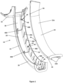
Figure 1 shows an exploded view of an embodiment of a hinge cover assembly in accordance with aspects of the invention; -
Figure 2 shows a perspective view of the hinge cover assembly ofFigure 1 in an assembled configuration; -
Figure 3 shows a side view of a swan neck type hinge with the hinge cover assembly ofFigures 1 and2 mounted to an arm of the hinge; -
Figure 3A is a cross-sectional view through the hinge arm and hinge cover assembly ofFigure 3 taken at the line A-A; -
Figure 3B is a cross-sectional view through the hinge arm and hinge cover assembly ofFigure 3 taken at the line B-B; -
Figure 4 shows an exploded view of part of the hinge cover assembly and swan neck type hinge ofFigure 3 in a pre-assembled configuration; -
Figure 5 shows a perspective view of part of a boot lid showing the hinge cover assembly ofFigures 1 and2 mounted to an arm of a swan neck hinge attached to the boot lid; -
Figure 6 is a cross sectional view through part of the boot lid ofFigure 5 showing a second mounting structure of the hinge ofFigure 3 adjustably attached to the boot lid; -
Figure 7 is a cross-sectional view through the hinge cover assembly and trim panel ofFigure 5 taken at the line C-C; -
Figure 8 is a further cross sectional view through the hinge cover assembly and trim panel ofFigure 5 taken along the line of C-C but viewed from the opposite side from that taken inFigure 7 and also showing details of the boot lid. - With reference initially to
Figures 1 to 4 , a first embodiment of ahinge cover assembly 10, in accordance with aspects of the invention will be described. Thehinge cover assembly 10 is adapted for use with a swan neck hinge 12 as illustrated inFigures 3 and4 . Hinges of this type are commonly used for mounting a movable closure to a vehicle body. In the embodiment described, the hinge is used to mount aboot lid 13 to the body of a vehicle. However, it should be appreciated that the invention is not limited to use with hinges for mounting boot lids but can be adapted for use with hinges for mounting other types of closure to a vehicle or indeed non-vehicular applications. - The
hinge 12 has anelongate hinge arm 14 and includes afirst mounting structure 16 at one end for attaching thehinge arm 14 to the body of a vehicle (not shown) and asecond mounting structure 18 at the other end for attaching thehinge arm 14 to theboot lid 13. The hinge arm is pivotally connected to each of the mountingstructures first mounting structure 16. - The
hinge cover assembly 10 includes afirst cover member 20 and asecond cover member 22. - The
first cover member 20 has an elongate channel shapedportion 24 having a pair ofopposed side walls wall 30. The channel shapedportion 24 is mounted over theelongate arm 14 of the swan neck hinge 12 to encapsulate the arm about three sides over part of its length. Thehinge arm 14 is curved in the longitudinal direction and the elongate channel shapedportion 24 is correspondingly curved to form a close fit over thehinge arm 12. At one end of the channel shapedportion 24 is a housing portion orflange 32. In use, thehousing portion 32 overlies part of theboot lid 13 so as to encase at least part of thesecond mounting structure 28. - The
second cover member 22 is releasably attachable to the channel shapedportion 24 of the first cover member so as to extend between the free ends of theside walls base region 30. Thesecond cover member 22 is an elongate U shaped member having abase 22A and a pair of depending flanges 22B. Thebase 22A is substantially planar in the lateral direction but curves in the longitudinal direction to conform to the curvature of the channel shapedportion 24. The flanges 22B are a close fit betweenside walls first cover member 20. At least the channel shapedportion 24 of thefirst cover member 20 is resiliently flexible so that theside walls hinge arm 14 and for mounting of thesecond cover member 22. The arrangement is such that thesecond cover member 22 is a tight fit between theside walls side wall apertures 36 are provided in each of the flanges 22B of the second cover member. Themale engagement members 34 are received in theapertures 36 to lock thesecond cover member 22 to thefirst cover member 20 when assembled. - In use, the channel shaped
portion 24 offirst cover member 20 is mounted to thehinge arm 14 as illustrated inFigures 3 ,3A and3B so that it extends about the hinge arm on the three most exposed sides of the arm. Thesecond cover member 22 is then mounted to thefirst cover member 22, as can be seen best inFigures 2 and3A , to cover the remaining side of thehinge arm 14 so that the arm is fully enclosed or encircled over at least part of its length. In use, thehinge cover assembly 10 encircles thehinge arm 14 of that part of its length which is generally exposed to view when the boot lid is open. - An embodiment for mounting of the
first cover member 20 to thehinge arm 14 is best seen inFigures 1 ,3A and3B . The spacing between theside walls portion 24 is larger than the width of thehinge arm 14. A number of locatingribs side walls 26. Theribs first side wall 26 over part of its height and are spaced apart along the length of the channel shapedportion 24. The locatingribs hinge arm 14 on one side. Some of theribs 40A only extend up the first side wall whilstothers 40B also extend laterally across the inner surface of thebase region 30 and up part of thesecond side wall 28. Theribs slot 40C at their upper end or ends into which the corresponding flange 22B of thesecond cover member 22 is received. Also associated with each of the laterally extendingribs 40B is aclamping formation 40D which projects inwardly from thebase region 30 in spaced relation to thefirst side wall 26. The clampingformations 40D define anabutment surface 42 which opposes thefirst side wall 26 and which in use contacts thehinge arm 14 on the opposite side from theribs ribs first side wall 26 and theclamping formations 40D. This locates thefirst cover member 20 relative to thehinge arm 14. Alongitudinal channel 44 is defined between thehinge arm 14 and thesecond side wall 28 through which cables or harnesses or other components can be routed. - To affix the
first cover member 20 to the hinge arm, a number of lockingprojections 46 extend inwardly (laterally) from the inner surface of thefirst side wall 26. The lockingprojections 46 in this embodiment are in the form of pegs or pins which extend inwardly by a greater distance then the locatingribs projection 46 is received in acorresponding locking aperture 48 defined in aside wall 50 of the hinge arm proximal thefirst side wall 26. To fit thefirst cover member 20 to thehinge arm 14, thefirst side wall 26 is flexed outwardly away from thesecond side wall 28 and theclamping formations 40D to enable the hinge arm to be located between thefist side wall 26 and theclamping formations 40D and to enable the lockingprojections 46 to slide up theside 50 of thehinge arm 14 to engage in theirrespective locking apertures 48. The lockingprojections 46 have a chamferedupper edge 52 which engages the hinge arm to force thefirst side wall 26 outwardly when the first cover member is pressed on to the hinge arm. Once the lockingprojections 46 have engaged in theirrespective locking apertures 48, the natural resilience of the material biases thefirst side wall 26 back to its rest position in which thehinge arm 14 is clamped between the locatingribs first side wall 26 and theclamping formations 40D and the lockingprojections 46 are firmly located in the lockingapertures 48. The firsthinge cover member 20 is arranged so that once fitted, it is a tight fit on thehinge arm 14. Any cables, harnesses or other components that are to be routed along thelongitudinal channel 44 can be arranged in position and fixed using ties as required. Thesecond cover member 22 is then pressed into position between the free ends of the first andsecond side walls second side walls second cover member 22 to be pressed into place. Once thesecond cover member 22 is in position, thehinge arm 14 is completely encircled by the hinge cover assembly on all sides so that no part of the hinge arm or any associated cables, harness or other components routed along the hinge are visible over at least part of the length of the hinge arm. This provides for a particularly neat appearance. Furthermore, since all the fittings for securing thefirst cover member 20 to hinge arm are located internally of the channel shapedportion 24, there no externally visible fixings which further provides for a neat and aesthetically pleasing finish. - The first and
second cover members - Other arrangements for attaching the
second cover member 22 to thefirst cover member 20 can be adopted. For example, the first and second cover members may have corresponding male and female connectors which can be engaged, say with a snap fit, to fix thesecond cover member 22 to thefirst cover member 20. It is preferable though that any such connectors should not be visible from the outside once the cover members are assembled together. - Whilst the use of two
cover members first cover member 20 may still be advantageous as it will enclose the hinge arm on the three most exposed sides but without any fixings that are visible once the cover member is mounted to the hinge arm. The firsthinge cover member 20 if used on its own may be modified to omit the mountingslots 40C and may be modified so that thesecond side wall 28 is located closer to hingearm 14. Thesecond side wall 28 could be adapted to contact thehinge arm 14 on the opposite side from the first side wall or be provided with locating ribs similar to theribs formations 40D. -
Figures 5 to 8 illustrate another aspect of the invention. The housing portion orflange 32 at the closure end of the elongate channel shapedportion 24 of the first cover member is arranged to overlie part of theinner face 54 of theboot lid 13 to which thehinge arm 14 is attached by the secondhinge mounting structure 18. Thehousing portion 32 thus covers the secondhinge mounting structure 18 where it locates on the boot lid so that the mounting structure is not visible. The housing portion is profiled to interface with atrim panel 56 mounted to the inner surface of theboot lid 13 and to conform to the shape of the boot lid to provide a neat finish. Thetrim panel 56 may comprise a section of carpet or other fabric, for example. - Typically, the
second mounting structure 18 is attached close to alower edge 58 of the boot lid and close to oneside edge 60. In order to conform to the shape of the boot lid, thehousing portion 32 has afirst section 62 which extends generally in a first plane overlying aninner face 54 of theboot lid 13 where thesecond mounting structure 18 is attached and asecond section 64 which overlies part of thelower edge 58 of the boot lid and which extends generally in a second plane perpendicular to the first plane. - As illustrated in
Figure 6 , the position of thesecond mounting structure 18 relative to theboot lid 13 is adjustable, typically in a direction perpendicular to the first plane as indicated byarrows 66. Since thehinge cover assembly 10 is mounted to thehinge arm 14 and thetrim panel 56 is mounted to the boot lid, adjusting the position of thesecond mounting structure 18 will result in relative movement between thehousing portion 32 and thetrim panel 56 which can affect the neatness of the finish. A particular issue is that relative movement between thesecond mounting structure 18 and the boot lid in a direction parallel to the first plane will result in thesecond section 64 of thehousing portion 32 moving towards or away from thelower edge 58 of the boot lid which can result in a gap appearing between thehousing portion 32 and thetrim panel 56. To address this issue, at least along part of aside edge 68 of thesecond section 64 of the housing portion, thehousing portion 32 defines aclip formation 70 which grips anedge region 72 of thetrim panel 56 and the trim panel has alive hinge 74 which extends generally parallel to therespective side edge 68 of the second section. With this arrangement, theedge region 72 of the trim panel is constrained to move with thehousing portion 32 if the position of thesecond mounting structure 18 on theboot lid 13 is adjusted, as is illustrated by the dashed lines at 76 inFigure 8 . This prevents gaps appearing between thehousing portion 32 and thetrim panel 56. - In the present embodiment, the
clip formation 70 comprises a C-section slot or recess in which theedge region 72 of the trim panel is inserted, the C-section being configured to clamp theedge region 72. However, other clip formations could be used an indeed other arrangements for securing theedge region 72 of the trim panel to the housing portion can be adopted. This aspect of the invention can be used where the hinge cover comprises afirst cover member 20 only or where the hinge cover is an assembly comprising first andsecond cover members - The above embodiments are described by way of example only. Many variations are possible without departing from the scope of the appended claims
Claims (15)
- A hinge cover member (10) for use with a swan neck type hinge (12) for attaching a closure to a vehicle body, the hinge having a mounting structure (18) at one end of a hinge arm (14) for attaching the hinge arm to the closure, the hinge cover member comprising an elongate channel shaped portion (20) for receiving the hinge arm and a housing portion (32) at one end of the elongate channel shaped portion configured to overlie part of a surface of the closure about the mounting structure, characterized in that the housing portion defines at least one formation (70) for attaching an edge (72) of a trim panel mounted to the closure, to the housing portion.
- A hinge cover member as claimed in claim 1, wherein the at least one formation is a clip formation for gripping said edge of the trim panel.
- A hinge cover member as claimed in claim 2, the at least one clip formation defining a slot along at least part of an edge of the housing portion into which an edge region of the trim panel is inserted in use.
- A hinge cover member as claimed in any one of claims 1 to 3, wherein the channel shaped portion defines a pair of spaced side walls (26, 28) interconnected at one end by a base region (30), the elongate channel shaped portion being resiliently deformable such that the side walls can be biased apart from a rest position, a plurality of locking projections (46) being provided on the inner surface of the elongate channel shaped portion for engagement with corresponding locking formations (48) on the hinge arm to secure the hinge cover member to the hinge arm.
- A hinge cover member as claimed in claim 4, wherein said plurality of locking projections are provided on the inner surface of at least one of the side walls.
- A hinge cover member as claimed in claim 5, wherein the side walls of the elongate channel shaped portion can be biased apart from the rest position to allow the hinge cover member to be mounted to the hinge arm in use.
- A hinge cover member as claimed in any one of claims 4 to 6, wherein a plurality of locating ribs are spaced apart along the inner surface of the elongate channel shaped portion for engagement with an outer surface of the hinge arm.
- A hinge cover member as claimed in claim 7, wherein the plurality of locating ribs comprise locating ribs on an inner surface of one of the side walls for engagement with a first side of the hinge arm, a plurality of clamping formations (40D) projecting from the inner surface of the base region in spaced relation said one of the side walls, the clamping formations configured to engage a second side of the hinge arm opposite the first side such that in use, the hinge arm is clamped between the clamping formations and the locating ribs on said one side wall of the elongate channel shaped portion.
- A vehicle having a body and a closure mounted to the body by a swan neck type hinge (12), the hinge having an elongate hinge arm (14) attached to the closure at one end by a mounting structure (18), wherein a hinge cover member (10) as claimed in any one of claims 1 to 8 is mounted to the hinge arm;and, optionally, wherein a trim panel (56) is mounted to the closure and an edge of the trim panel is attached to the housing portion by said formation;and, optionally, wherein said formation is a clip formation, an edge of the trim panel being clamped in the clip formation.
- A vehicle as claimed in claim 9, wherein the trim panel has a live hinge proximal said edge.
- A vehicle as claimed in either of claims 9 or 10, wherein the hinge cover member is configured in accordance any one of claims 4 to 8, the hinge arm defining corresponding locking formations (48) in the form of locking apertures in which the locking projections engage to secure the hinge cover member to the hinge arm.
- A vehicle as claimed in claim 11, wherein the locking apertures are defined in a side region of the hinge arm.
- A vehicle as claimed in any one of claims 9 to 12, wherein the hinge cover is configured in accordance with claim 8 and wherein the hinge arm is clamped between the locating ribs on said one of the side walls of the elongate channel shaped portion of the hinge cover member and the clamping formations.
- A vehicle as claimed in claim 13, wherein the spacing between the side walls of the elongate channel shaped portion of the hinge cover member is greater than the width of the hinge arm.
- A vehicle as claimed in any one of claims 9 to 14, wherein the closure is a boot lid.
Applications Claiming Priority (2)
| Application Number | Priority Date | Filing Date | Title |
|---|---|---|---|
| GB1800907.6A GB2570321B (en) | 2018-01-19 | 2018-01-19 | A hinge cover and vehicle |
| PCT/GB2019/050010 WO2019141964A1 (en) | 2018-01-19 | 2019-01-03 | A hinge cover and vehicle |
Publications (2)
| Publication Number | Publication Date |
|---|---|
| EP3740635A1 EP3740635A1 (en) | 2020-11-25 |
| EP3740635B1 true EP3740635B1 (en) | 2023-10-25 |
Family
ID=61283463
Family Applications (1)
| Application Number | Title | Priority Date | Filing Date |
|---|---|---|---|
| EP19700542.4A Active EP3740635B1 (en) | 2018-01-19 | 2019-01-03 | A hinge cover and vehicle |
Country Status (4)
| Country | Link |
|---|---|
| US (1) | US11433828B2 (en) |
| EP (1) | EP3740635B1 (en) |
| GB (1) | GB2570321B (en) |
| WO (1) | WO2019141964A1 (en) |
Families Citing this family (7)
| Publication number | Priority date | Publication date | Assignee | Title |
|---|---|---|---|---|
| GB2570322B (en) * | 2018-01-19 | 2021-08-04 | Bentley Motors Ltd | A hinge cover and vehicle |
| GB2570321B (en) | 2018-01-19 | 2021-05-05 | Bentley Motors Ltd | A hinge cover and vehicle |
| JP7297806B2 (en) * | 2021-03-29 | 2023-06-26 | 矢崎総業株式会社 | protector |
| US11920391B2 (en) | 2021-09-10 | 2024-03-05 | Dee Zee, Inc. | Hinge covers for exposed vehicle door hinges |
| USD1085968S1 (en) | 2021-10-29 | 2025-07-29 | Dee Zee, Inc. | Vehicle door hinge cover |
| USD1076749S1 (en) * | 2023-09-01 | 2025-05-27 | Volvo Truck Corporation | Trim for vehicle interior |
| DE102024113351A1 (en) | 2024-05-14 | 2025-11-20 | Audi Aktiengesellschaft | A flap device for covering a storage compartment of a motor vehicle, and a motor vehicle with a flap device |
Family Cites Families (16)
| Publication number | Priority date | Publication date | Assignee | Title |
|---|---|---|---|---|
| JP2964445B2 (en) | 1994-11-08 | 1999-10-18 | 矢崎総業株式会社 | Harness protector |
| JP3260114B2 (en) * | 1997-10-31 | 2002-02-25 | 矢崎総業株式会社 | Striatal protector |
| US6572177B2 (en) | 2001-01-29 | 2003-06-03 | Westinghouse Air Brake Technologies Corporation | Cover for flexible signal connection for a transit vehicle door |
| US20030038500A1 (en) | 2001-08-22 | 2003-02-27 | Aubry Michael Eugene | Vehicle deck lid power operator |
| EP1363375B1 (en) | 2002-05-14 | 2010-11-17 | Yazaki Corporation | Wire harness protector |
| KR100850982B1 (en) * | 2007-11-13 | 2008-08-12 | 현대자동차주식회사 | Trunk room hinge cover |
| EP2085550B1 (en) * | 2008-01-31 | 2011-10-19 | Honda Motor Co., Ltd. | Hinge structure for vehicle open/close body |
| JP5381290B2 (en) * | 2009-04-28 | 2014-01-08 | スズキ株式会社 | Automobile trunk lid switchgear |
| DE102013111309A1 (en) * | 2013-10-14 | 2015-04-16 | Euwe Eugen Wexler Gmbh | Interior trim element for a motor vehicle |
| JP6156139B2 (en) | 2013-12-27 | 2017-07-05 | マツダ株式会社 | Trunk lid hinge structure |
| US9701259B2 (en) * | 2014-01-02 | 2017-07-11 | Toyota Motor Engineering & Manufacturing North America, Inc. | Hinge arm fitting feature |
| US9435151B2 (en) | 2014-01-29 | 2016-09-06 | Toyota Motor Engineering & Manufacturing North America, Inc. | Cover assembly for attaching to a hinge arm |
| JP6172076B2 (en) * | 2014-07-17 | 2017-08-02 | マツダ株式会社 | Trunk lid hinge structure |
| KR20170069718A (en) * | 2015-12-11 | 2017-06-21 | 현대자동차주식회사 | Fastener of door trim for automobile |
| US10221596B1 (en) | 2017-10-17 | 2019-03-05 | GM Global Technology Operations LLC | Telescopic trunk lid support device |
| GB2570321B (en) | 2018-01-19 | 2021-05-05 | Bentley Motors Ltd | A hinge cover and vehicle |
-
2018
- 2018-01-19 GB GB1800907.6A patent/GB2570321B/en active Active
-
2019
- 2019-01-03 EP EP19700542.4A patent/EP3740635B1/en active Active
- 2019-01-03 WO PCT/GB2019/050010 patent/WO2019141964A1/en not_active Ceased
- 2019-01-19 US US16/963,195 patent/US11433828B2/en active Active
Also Published As
| Publication number | Publication date |
|---|---|
| EP3740635A1 (en) | 2020-11-25 |
| GB2570321B (en) | 2021-05-05 |
| GB2570321A (en) | 2019-07-24 |
| GB201800907D0 (en) | 2018-03-07 |
| US11433828B2 (en) | 2022-09-06 |
| US20210122300A1 (en) | 2021-04-29 |
| WO2019141964A1 (en) | 2019-07-25 |
Similar Documents
| Publication | Publication Date | Title |
|---|---|---|
| EP3740635B1 (en) | A hinge cover and vehicle | |
| US7420125B2 (en) | Grommet assembly | |
| US11293207B2 (en) | Two part boot hinge cover | |
| EP1363375B1 (en) | Wire harness protector | |
| US9511725B2 (en) | Wiring harness wiring structure | |
| US6070931A (en) | Assembly structure of an automotive door harness | |
| US7380310B2 (en) | Hidden hinge | |
| US10899294B2 (en) | Grommet assembly | |
| JPH1016672A (en) | Vehicle door harness assembly structure | |
| US10207661B2 (en) | Grommet | |
| US11066024B2 (en) | Grommet assembly | |
| US10724562B2 (en) | Line securement lock | |
| DK2024979T3 (en) | An apparatus for absorbing noise | |
| CN103502054A (en) | Wire harness routing structure section | |
| US6467220B1 (en) | Device for fastening a lock module on a vehicle door | |
| EP2940236B1 (en) | Damper, striker assembly and vehicle | |
| JP5040837B2 (en) | Clamp | |
| EP0378419B1 (en) | Front loading flush glass run system | |
| US5307248A (en) | Underhood lamp wiring strap | |
| JPH0623142Y2 (en) | Wiring equipment | |
| JP3711087B2 (en) | Protector mounting structure | |
| US6978519B2 (en) | Device for adjusting and locking a strap | |
| JP5920285B2 (en) | Grommet for door and wire harness with grommet | |
| JPH07304370A (en) | Door grip structure | |
| JP7391191B2 (en) | cable mold |
Legal Events
| Date | Code | Title | Description |
|---|---|---|---|
| STAA | Information on the status of an ep patent application or granted ep patent |
Free format text: STATUS: UNKNOWN |
|
| STAA | Information on the status of an ep patent application or granted ep patent |
Free format text: STATUS: THE INTERNATIONAL PUBLICATION HAS BEEN MADE |
|
| PUAI | Public reference made under article 153(3) epc to a published international application that has entered the european phase |
Free format text: ORIGINAL CODE: 0009012 |
|
| STAA | Information on the status of an ep patent application or granted ep patent |
Free format text: STATUS: REQUEST FOR EXAMINATION WAS MADE |
|
| 17P | Request for examination filed |
Effective date: 20200630 |
|
| AK | Designated contracting states |
Kind code of ref document: A1 Designated state(s): AL AT BE BG CH CY CZ DE DK EE ES FI FR GB GR HR HU IE IS IT LI LT LU LV MC MK MT NL NO PL PT RO RS SE SI SK SM TR |
|
| AX | Request for extension of the european patent |
Extension state: BA ME |
|
| DAV | Request for validation of the european patent (deleted) | ||
| DAX | Request for extension of the european patent (deleted) | ||
| STAA | Information on the status of an ep patent application or granted ep patent |
Free format text: STATUS: EXAMINATION IS IN PROGRESS |
|
| 17Q | First examination report despatched |
Effective date: 20220810 |
|
| P01 | Opt-out of the competence of the unified patent court (upc) registered |
Effective date: 20230418 |
|
| GRAP | Despatch of communication of intention to grant a patent |
Free format text: ORIGINAL CODE: EPIDOSNIGR1 |
|
| STAA | Information on the status of an ep patent application or granted ep patent |
Free format text: STATUS: GRANT OF PATENT IS INTENDED |
|
| INTG | Intention to grant announced |
Effective date: 20230706 |
|
| GRAS | Grant fee paid |
Free format text: ORIGINAL CODE: EPIDOSNIGR3 |
|
| GRAA | (expected) grant |
Free format text: ORIGINAL CODE: 0009210 |
|
| STAA | Information on the status of an ep patent application or granted ep patent |
Free format text: STATUS: THE PATENT HAS BEEN GRANTED |
|
| AK | Designated contracting states |
Kind code of ref document: B1 Designated state(s): AL AT BE BG CH CY CZ DE DK EE ES FI FR GB GR HR HU IE IS IT LI LT LU LV MC MK MT NL NO PL PT RO RS SE SI SK SM TR |
|
| REG | Reference to a national code |
Ref country code: GB Ref legal event code: FG4D |
|
| REG | Reference to a national code |
Ref country code: CH Ref legal event code: EP |
|
| REG | Reference to a national code |
Ref country code: DE Ref legal event code: R096 Ref document number: 602019039985 Country of ref document: DE |
|
| REG | Reference to a national code |
Ref country code: IE Ref legal event code: FG4D |
|
| REG | Reference to a national code |
Ref country code: LT Ref legal event code: MG9D |
|
| REG | Reference to a national code |
Ref country code: NL Ref legal event code: MP Effective date: 20231025 |
|
| REG | Reference to a national code |
Ref country code: AT Ref legal event code: MK05 Ref document number: 1624815 Country of ref document: AT Kind code of ref document: T Effective date: 20231025 |
|
| PG25 | Lapsed in a contracting state [announced via postgrant information from national office to epo] |
Ref country code: NL Free format text: LAPSE BECAUSE OF FAILURE TO SUBMIT A TRANSLATION OF THE DESCRIPTION OR TO PAY THE FEE WITHIN THE PRESCRIBED TIME-LIMIT Effective date: 20231025 |
|
| PG25 | Lapsed in a contracting state [announced via postgrant information from national office to epo] |
Ref country code: GR Free format text: LAPSE BECAUSE OF FAILURE TO SUBMIT A TRANSLATION OF THE DESCRIPTION OR TO PAY THE FEE WITHIN THE PRESCRIBED TIME-LIMIT Effective date: 20240126 |
|
| PG25 | Lapsed in a contracting state [announced via postgrant information from national office to epo] |
Ref country code: IS Free format text: LAPSE BECAUSE OF FAILURE TO SUBMIT A TRANSLATION OF THE DESCRIPTION OR TO PAY THE FEE WITHIN THE PRESCRIBED TIME-LIMIT Effective date: 20240225 |
|
| PG25 | Lapsed in a contracting state [announced via postgrant information from national office to epo] |
Ref country code: LT Free format text: LAPSE BECAUSE OF FAILURE TO SUBMIT A TRANSLATION OF THE DESCRIPTION OR TO PAY THE FEE WITHIN THE PRESCRIBED TIME-LIMIT Effective date: 20231025 |
|
| PG25 | Lapsed in a contracting state [announced via postgrant information from national office to epo] |
Ref country code: AT Free format text: LAPSE BECAUSE OF FAILURE TO SUBMIT A TRANSLATION OF THE DESCRIPTION OR TO PAY THE FEE WITHIN THE PRESCRIBED TIME-LIMIT Effective date: 20231025 |
|
| PG25 | Lapsed in a contracting state [announced via postgrant information from national office to epo] |
Ref country code: ES Free format text: LAPSE BECAUSE OF FAILURE TO SUBMIT A TRANSLATION OF THE DESCRIPTION OR TO PAY THE FEE WITHIN THE PRESCRIBED TIME-LIMIT Effective date: 20231025 |
|
| PG25 | Lapsed in a contracting state [announced via postgrant information from national office to epo] |
Ref country code: LT Free format text: LAPSE BECAUSE OF FAILURE TO SUBMIT A TRANSLATION OF THE DESCRIPTION OR TO PAY THE FEE WITHIN THE PRESCRIBED TIME-LIMIT Effective date: 20231025 Ref country code: IS Free format text: LAPSE BECAUSE OF FAILURE TO SUBMIT A TRANSLATION OF THE DESCRIPTION OR TO PAY THE FEE WITHIN THE PRESCRIBED TIME-LIMIT Effective date: 20240225 Ref country code: GR Free format text: LAPSE BECAUSE OF FAILURE TO SUBMIT A TRANSLATION OF THE DESCRIPTION OR TO PAY THE FEE WITHIN THE PRESCRIBED TIME-LIMIT Effective date: 20240126 Ref country code: ES Free format text: LAPSE BECAUSE OF FAILURE TO SUBMIT A TRANSLATION OF THE DESCRIPTION OR TO PAY THE FEE WITHIN THE PRESCRIBED TIME-LIMIT Effective date: 20231025 Ref country code: BG Free format text: LAPSE BECAUSE OF FAILURE TO SUBMIT A TRANSLATION OF THE DESCRIPTION OR TO PAY THE FEE WITHIN THE PRESCRIBED TIME-LIMIT Effective date: 20240125 Ref country code: AT Free format text: LAPSE BECAUSE OF FAILURE TO SUBMIT A TRANSLATION OF THE DESCRIPTION OR TO PAY THE FEE WITHIN THE PRESCRIBED TIME-LIMIT Effective date: 20231025 Ref country code: PT Free format text: LAPSE BECAUSE OF FAILURE TO SUBMIT A TRANSLATION OF THE DESCRIPTION OR TO PAY THE FEE WITHIN THE PRESCRIBED TIME-LIMIT Effective date: 20240226 |
|
| PG25 | Lapsed in a contracting state [announced via postgrant information from national office to epo] |
Ref country code: SE Free format text: LAPSE BECAUSE OF FAILURE TO SUBMIT A TRANSLATION OF THE DESCRIPTION OR TO PAY THE FEE WITHIN THE PRESCRIBED TIME-LIMIT Effective date: 20231025 Ref country code: RS Free format text: LAPSE BECAUSE OF FAILURE TO SUBMIT A TRANSLATION OF THE DESCRIPTION OR TO PAY THE FEE WITHIN THE PRESCRIBED TIME-LIMIT Effective date: 20231025 Ref country code: PL Free format text: LAPSE BECAUSE OF FAILURE TO SUBMIT A TRANSLATION OF THE DESCRIPTION OR TO PAY THE FEE WITHIN THE PRESCRIBED TIME-LIMIT Effective date: 20231025 Ref country code: NO Free format text: LAPSE BECAUSE OF FAILURE TO SUBMIT A TRANSLATION OF THE DESCRIPTION OR TO PAY THE FEE WITHIN THE PRESCRIBED TIME-LIMIT Effective date: 20240125 Ref country code: LV Free format text: LAPSE BECAUSE OF FAILURE TO SUBMIT A TRANSLATION OF THE DESCRIPTION OR TO PAY THE FEE WITHIN THE PRESCRIBED TIME-LIMIT Effective date: 20231025 Ref country code: HR Free format text: LAPSE BECAUSE OF FAILURE TO SUBMIT A TRANSLATION OF THE DESCRIPTION OR TO PAY THE FEE WITHIN THE PRESCRIBED TIME-LIMIT Effective date: 20231025 |
|
| PG25 | Lapsed in a contracting state [announced via postgrant information from national office to epo] |
Ref country code: DK Free format text: LAPSE BECAUSE OF FAILURE TO SUBMIT A TRANSLATION OF THE DESCRIPTION OR TO PAY THE FEE WITHIN THE PRESCRIBED TIME-LIMIT Effective date: 20231025 |
|
| PG25 | Lapsed in a contracting state [announced via postgrant information from national office to epo] |
Ref country code: CZ Free format text: LAPSE BECAUSE OF FAILURE TO SUBMIT A TRANSLATION OF THE DESCRIPTION OR TO PAY THE FEE WITHIN THE PRESCRIBED TIME-LIMIT Effective date: 20231025 |
|
| REG | Reference to a national code |
Ref country code: DE Ref legal event code: R097 Ref document number: 602019039985 Country of ref document: DE |
|
| PG25 | Lapsed in a contracting state [announced via postgrant information from national office to epo] |
Ref country code: SK Free format text: LAPSE BECAUSE OF FAILURE TO SUBMIT A TRANSLATION OF THE DESCRIPTION OR TO PAY THE FEE WITHIN THE PRESCRIBED TIME-LIMIT Effective date: 20231025 |
|
| PG25 | Lapsed in a contracting state [announced via postgrant information from national office to epo] |
Ref country code: SM Free format text: LAPSE BECAUSE OF FAILURE TO SUBMIT A TRANSLATION OF THE DESCRIPTION OR TO PAY THE FEE WITHIN THE PRESCRIBED TIME-LIMIT Effective date: 20231025 Ref country code: SK Free format text: LAPSE BECAUSE OF FAILURE TO SUBMIT A TRANSLATION OF THE DESCRIPTION OR TO PAY THE FEE WITHIN THE PRESCRIBED TIME-LIMIT Effective date: 20231025 Ref country code: RO Free format text: LAPSE BECAUSE OF FAILURE TO SUBMIT A TRANSLATION OF THE DESCRIPTION OR TO PAY THE FEE WITHIN THE PRESCRIBED TIME-LIMIT Effective date: 20231025 Ref country code: IT Free format text: LAPSE BECAUSE OF FAILURE TO SUBMIT A TRANSLATION OF THE DESCRIPTION OR TO PAY THE FEE WITHIN THE PRESCRIBED TIME-LIMIT Effective date: 20231025 Ref country code: EE Free format text: LAPSE BECAUSE OF FAILURE TO SUBMIT A TRANSLATION OF THE DESCRIPTION OR TO PAY THE FEE WITHIN THE PRESCRIBED TIME-LIMIT Effective date: 20231025 Ref country code: DK Free format text: LAPSE BECAUSE OF FAILURE TO SUBMIT A TRANSLATION OF THE DESCRIPTION OR TO PAY THE FEE WITHIN THE PRESCRIBED TIME-LIMIT Effective date: 20231025 Ref country code: CZ Free format text: LAPSE BECAUSE OF FAILURE TO SUBMIT A TRANSLATION OF THE DESCRIPTION OR TO PAY THE FEE WITHIN THE PRESCRIBED TIME-LIMIT Effective date: 20231025 |
|
| PG25 | Lapsed in a contracting state [announced via postgrant information from national office to epo] |
Ref country code: MC Free format text: LAPSE BECAUSE OF FAILURE TO SUBMIT A TRANSLATION OF THE DESCRIPTION OR TO PAY THE FEE WITHIN THE PRESCRIBED TIME-LIMIT Effective date: 20231025 |
|
| PG25 | Lapsed in a contracting state [announced via postgrant information from national office to epo] |
Ref country code: MC Free format text: LAPSE BECAUSE OF FAILURE TO SUBMIT A TRANSLATION OF THE DESCRIPTION OR TO PAY THE FEE WITHIN THE PRESCRIBED TIME-LIMIT Effective date: 20231025 |
|
| PLBE | No opposition filed within time limit |
Free format text: ORIGINAL CODE: 0009261 |
|
| REG | Reference to a national code |
Ref country code: CH Ref legal event code: PL |
|
| STAA | Information on the status of an ep patent application or granted ep patent |
Free format text: STATUS: NO OPPOSITION FILED WITHIN TIME LIMIT |
|
| PG25 | Lapsed in a contracting state [announced via postgrant information from national office to epo] |
Ref country code: LU Free format text: LAPSE BECAUSE OF NON-PAYMENT OF DUE FEES Effective date: 20240103 |
|
| PG25 | Lapsed in a contracting state [announced via postgrant information from national office to epo] |
Ref country code: LU Free format text: LAPSE BECAUSE OF NON-PAYMENT OF DUE FEES Effective date: 20240103 |
|
| 26N | No opposition filed |
Effective date: 20240726 |
|
| PG25 | Lapsed in a contracting state [announced via postgrant information from national office to epo] |
Ref country code: BE Free format text: LAPSE BECAUSE OF NON-PAYMENT OF DUE FEES Effective date: 20240131 |
|
| PG25 | Lapsed in a contracting state [announced via postgrant information from national office to epo] |
Ref country code: CH Free format text: LAPSE BECAUSE OF NON-PAYMENT OF DUE FEES Effective date: 20240131 |
|
| PG25 | Lapsed in a contracting state [announced via postgrant information from national office to epo] |
Ref country code: SI Free format text: LAPSE BECAUSE OF FAILURE TO SUBMIT A TRANSLATION OF THE DESCRIPTION OR TO PAY THE FEE WITHIN THE PRESCRIBED TIME-LIMIT Effective date: 20231025 |
|
| PG25 | Lapsed in a contracting state [announced via postgrant information from national office to epo] |
Ref country code: SI Free format text: LAPSE BECAUSE OF FAILURE TO SUBMIT A TRANSLATION OF THE DESCRIPTION OR TO PAY THE FEE WITHIN THE PRESCRIBED TIME-LIMIT Effective date: 20231025 Ref country code: CH Free format text: LAPSE BECAUSE OF NON-PAYMENT OF DUE FEES Effective date: 20240131 Ref country code: BE Free format text: LAPSE BECAUSE OF NON-PAYMENT OF DUE FEES Effective date: 20240131 |
|
| REG | Reference to a national code |
Ref country code: BE Ref legal event code: MM Effective date: 20240131 |
|
| PGFP | Annual fee paid to national office [announced via postgrant information from national office to epo] |
Ref country code: FR Payment date: 20241227 Year of fee payment: 7 |
|
| PG25 | Lapsed in a contracting state [announced via postgrant information from national office to epo] |
Ref country code: IE Free format text: LAPSE BECAUSE OF NON-PAYMENT OF DUE FEES Effective date: 20240103 |
|
| PG25 | Lapsed in a contracting state [announced via postgrant information from national office to epo] |
Ref country code: IE Free format text: LAPSE BECAUSE OF NON-PAYMENT OF DUE FEES Effective date: 20240103 |
|
| PG25 | Lapsed in a contracting state [announced via postgrant information from national office to epo] |
Ref country code: CY Free format text: LAPSE BECAUSE OF FAILURE TO SUBMIT A TRANSLATION OF THE DESCRIPTION OR TO PAY THE FEE WITHIN THE PRESCRIBED TIME-LIMIT; INVALID AB INITIO Effective date: 20190103 |
|
| PG25 | Lapsed in a contracting state [announced via postgrant information from national office to epo] |
Ref country code: HU Free format text: LAPSE BECAUSE OF FAILURE TO SUBMIT A TRANSLATION OF THE DESCRIPTION OR TO PAY THE FEE WITHIN THE PRESCRIBED TIME-LIMIT; INVALID AB INITIO Effective date: 20190103 |
|
| PG25 | Lapsed in a contracting state [announced via postgrant information from national office to epo] |
Ref country code: FI Free format text: LAPSE BECAUSE OF FAILURE TO SUBMIT A TRANSLATION OF THE DESCRIPTION OR TO PAY THE FEE WITHIN THE PRESCRIBED TIME-LIMIT Effective date: 20231025 |
|
| PG25 | Lapsed in a contracting state [announced via postgrant information from national office to epo] |
Ref country code: TR Free format text: LAPSE BECAUSE OF FAILURE TO SUBMIT A TRANSLATION OF THE DESCRIPTION OR TO PAY THE FEE WITHIN THE PRESCRIBED TIME-LIMIT Effective date: 20231025 |
|
| PGFP | Annual fee paid to national office [announced via postgrant information from national office to epo] |
Ref country code: GB Payment date: 20260105 Year of fee payment: 8 |
|
| PGFP | Annual fee paid to national office [announced via postgrant information from national office to epo] |
Ref country code: DE Payment date: 20260130 Year of fee payment: 8 |