EP3740424B1 - U-tank active roll dampening system for and method for active roll dampening of a vessel - Google Patents
U-tank active roll dampening system for and method for active roll dampening of a vessel Download PDFInfo
- Publication number
- EP3740424B1 EP3740424B1 EP19741270.3A EP19741270A EP3740424B1 EP 3740424 B1 EP3740424 B1 EP 3740424B1 EP 19741270 A EP19741270 A EP 19741270A EP 3740424 B1 EP3740424 B1 EP 3740424B1
- Authority
- EP
- European Patent Office
- Prior art keywords
- tank
- vessel
- air pressure
- vacuum
- tanks
- Prior art date
- Legal status (The legal status is an assumption and is not a legal conclusion. Google has not performed a legal analysis and makes no representation as to the accuracy of the status listed.)
- Active
Links
- 238000000034 method Methods 0.000 title claims description 19
- 239000012530 fluid Substances 0.000 claims description 146
- 230000033001 locomotion Effects 0.000 claims description 65
- 238000005273 aeration Methods 0.000 claims description 50
- 238000005259 measurement Methods 0.000 claims description 15
- 230000001133 acceleration Effects 0.000 claims description 8
- 238000009423 ventilation Methods 0.000 claims description 5
- 230000001965 increasing effect Effects 0.000 claims description 4
- 230000003028 elevating effect Effects 0.000 description 3
- 239000007788 liquid Substances 0.000 description 3
- 238000013016 damping Methods 0.000 description 2
- 238000010586 diagram Methods 0.000 description 2
- 230000006641 stabilisation Effects 0.000 description 2
- 238000011105 stabilization Methods 0.000 description 2
- 238000013461 design Methods 0.000 description 1
- 238000009434 installation Methods 0.000 description 1
- 238000012423 maintenance Methods 0.000 description 1
- 239000013535 sea water Substances 0.000 description 1
- 239000003381 stabilizer Substances 0.000 description 1
- 230000000087 stabilizing effect Effects 0.000 description 1
- 238000012546 transfer Methods 0.000 description 1
- XLYOFNOQVPJJNP-UHFFFAOYSA-N water Substances O XLYOFNOQVPJJNP-UHFFFAOYSA-N 0.000 description 1
Images


Classifications
-
- B—PERFORMING OPERATIONS; TRANSPORTING
- B63—SHIPS OR OTHER WATERBORNE VESSELS; RELATED EQUIPMENT
- B63B—SHIPS OR OTHER WATERBORNE VESSELS; EQUIPMENT FOR SHIPPING
- B63B39/00—Equipment to decrease pitch, roll, or like unwanted vessel movements; Apparatus for indicating vessel attitude
- B63B39/02—Equipment to decrease pitch, roll, or like unwanted vessel movements; Apparatus for indicating vessel attitude to decrease vessel movements by displacement of masses
- B63B39/03—Equipment to decrease pitch, roll, or like unwanted vessel movements; Apparatus for indicating vessel attitude to decrease vessel movements by displacement of masses by transferring liquids
-
- B—PERFORMING OPERATIONS; TRANSPORTING
- B63—SHIPS OR OTHER WATERBORNE VESSELS; RELATED EQUIPMENT
- B63B—SHIPS OR OTHER WATERBORNE VESSELS; EQUIPMENT FOR SHIPPING
- B63B79/00—Monitoring properties or operating parameters of vessels in operation
- B63B79/40—Monitoring properties or operating parameters of vessels in operation for controlling the operation of vessels, e.g. monitoring their speed, routing or maintenance schedules
Description
- The present invention is related to a U-tank active roll dampening system for vessel, according to the preamble of claim 1.
- The present invention is also related to a method for active roll dampening of a vessel provided with a U-tank, according to the preamble of
claim 10. - The use of U-tube tanks was pioneered by Frahm in Germany at the start of the 20th century and they are often referred to as Frahm tanks. These partially filled tanks consists of two side tanks connected at the bottom by a substantial crossover duct. The air columns above the liquid in the two tanks are also connected by a duct. As in the free surface tanks, as the ship begins to roll the fluid flows from side tank to side tank causing a time varying roll moment to the ship and with careful design this roll moment is of correct phasing to reduce the roll motion of the ship. They do not restrict fore and aft passage as space above and below the crossover duct is available for other purposes.
-
JP7251793A KR20160104884A JP7251793A KR101235329 B1 KR20150045323A - There is also known to use a pump in the crossover duct to control the fluid volume in the side tanks.
- These pumps have the problem to active transfer enough volume capacity for roll damping, but sufficient in "Anti-Heeling" system.
-
GB 1213853 A GB 1213853 A GB 1213853 A GB 1213853 A GB 1213853 A -
GB 2087818 A GB 1213853 A GB 1213853 A GB 1213853 A - The mentioned U-tank systems are mainly designed for Anti-heeling when utilizing blowers at top of the tanks, but in addition these systems can provide passive roll dampening by means of free flow of fluid between the tanks as a result of the vessel roll motions, with full opening of tank airings between the top of the tanks, wherein the fluid flow is designed to the shortest roll period of the vessel. If the vessel should have a longer roll period the tank airings at top of the tanks are reduced for reducing the velocity of the fluid flow between the tanks. In such a passive roll dampening mode the system attempts to achieve the flow of fluid as close to 90 degrees after the vessel roll movement period.
- Accordingly, prior art solutions fail to provide an active roll dampening and there is a need for a U-tank active roll dampening system for and method for active roll dampening of a vessel provided with a U-tank.
- The prior art solutions further suffer from that they are not capable of providing the volume capacity or response time required to counteract the roll affection from waves before they have started to affect the vessel, only after, and accordingly will not be able to provide an active roll dampening of the vessel. Accordingly, prior art solution are not arranged or capable of moving sufficient fluid volume in advance, approximately 90 degrees in front of a roll motion.
- The main object of the present invention is to provide a U-tank active roll dampening system for and a method for active roll dampening of a vessel that partly or entirely solve the drawbacks of prior art.
- It is further an object of the present invention to provide a U-tank active roll dampening system for and method for active roll dampening of a vessel enabling counteraction of roll motions on the vessel before the waves have started to affect the vessel.
- An object of the present invention is to provide a U-tank active roll dampening system for and method for active roll dampening of a vessel enabling sufficient volume capacity capable of moving sufficient fluid volume between side tanks thereof in anti-phase in front of vessel roll motion period.
- It is an object of the present invention to provide a U-tank active roll dampening system for and method for active roll dampening of a vessel wherein controlling fluid level in one of the side tanks thereof also controls the fluid level in the other side tank.
- It is an object of the present invention to provide a U-tank active roll dampening system for and method for active roll dampening of a vessel that can make use of present U-tank system installed on vessel and used for anti-heeling.
- Further objects of the present invention will appear from the following description, claims and attached drawings.
- A U-tank active roll dampening system for vessel according to the present invention is disclosed in claim 1. Preferable features of the system are disclosed in claims 2-9.
- A method for active roll dampening of a vessel provided with a U-tank is disclosed in
claim 10. Preferable features of the method are disclosed in claims 11-12. - The present invention discloses an active roll dampening system for and method for active roll dampening of a vessel based on a U-tank. The U-tank is formed by a port side tank and a starboard side tank, the side tanks at upper end sealed and at lower end connected by a crossover duct, wherein the U-tank is partly filled with a fluid, which typically is water or seawater. The actual fluid volume inside the U-tank must be defined by the crew based on the actual loading of the vessel. The U-tank active roll dampening system according to the present invention further comprises at least one vacuum and air pressure manipulation unit arranged to upper part of an associated side tank and at least one aeration device against open air connected to upper part of the other side tank. According to the present invention the at least one vacuum and air pressure manipulation unit is arranged to supply air pressure or vacuum on fluid surface in the associated side tank with the other side tank open for aeration to open air to control fluid level in both side tanks.
- According to a second embodiment of the U-tank active roll dampening system according to the present invention the at least one vacuum and air pressure manipulation unit is arranged to supply air pressure on fluid surface of the other side tank via a controllable valve. Accordingly, the other tank is connected to the pressure side of the vacuum and air pressure manipulation unit via the controllable valve. In this embodiment there are further arranged aeration devices to both the side tanks. This embodiment will be especially suitable for solutions where the fluid level difference between the two side tanks have to be larger than 5 meters, i.e. the fluid level in the side tank associated with the at least one vacuum and air pressure manipulation unit is to be higher than 5 meters above the fluid level in the other side tank. By this embodiment, after a fluid level difference of 5 meters is achieved, the aeration device of the side tank associated with the vacuum and air pressure manipulation unit is set open to air, while the aeration device of the other side tank is closed and wherein the vacuum and air pressure manipulation unit is set to supply air pressure on the fluid surface of other side tank, whereupon the fluid level will further be lowered in the other side tank and correspondingly increased in the side tank associated with the vacuum and air pressure manipulation unit. In an alternative embodiment at least one separate air pressure unit is connected to the other tank instead of the vacuum and air pressure manipulation unit for supplying pressure on the fluid surface in the other side tank.
- In one embodiment of the U-tank active roll dampening system according to the present invention the vacuum and air pressure manipulation unit comprises at least one vacuum and air pressure generation unit connected to a demand controlled ventilation unit enabling controlled switching between supply of vacuum or pressure. In an alternative embodiment two or more vacuum and air pressure generation units are connected to a common demand controlled ventilation unit. According to a further embodiment the U-tank active roll dampening system according to the present invention it comprises two or more of the vacuum and air pressure manipulation units arranged to the same side tank.
- This will enable different configurations as well as redundancy.
- According to a further embodiment of the system according to the present invention the vacuum and air pressure manipulation unit is provided with a valve for opening or closing the connection to the associated side tank and the aeration device(s) is/are provided with a valve for opening or closing the aeration to open air.
- In a further embodiment of the U-tank active roll dampening system for vessel according to the present invention, the vacuum and air pressure manipulation unit is arranged for aeration against open air of the associated side tank. By this the system according to the present invention can operate in passive mode. Alternatively a separate aeration device can be arranged for this.
- By means of the mentioned valves of the vacuum and air pressure manipulation unit and aeration device(s), respectively, the system according to the present invention can operate in a stabilized mode locking the fluid level in the side tanks at a desired level by closing the mentioned valves.
- According to the present invention the U-tank active roll dampening system comprises at least one fluid level sensors arranged in each of the side tanks for measuring fluid level in the associated tank.
- The U-tank active roll dampening system for vessel according to the present invention further comprises a dedicated motion reference unit (MRU) for measuring accelerations of the vessel in a roll motion.
- According to the present invention the U-tank active roll dampening system further comprises a control unit arranged for controlling the vacuum and air pressure manipulation unit and aeration device(s), as well as associated valves and further is provided with means and/or software for controlling the fluid level in the side tanks based on measurements by the dedicated motion reference unit and measurements from the fluid level sensors so as to control the fluid level in the respective side tanks in anti-phase in front of the vessel roll motion period, approximately 90 degrees in front of a roll motion period.
- Accordingly, the present invention provides a U-tank active roll dampening system capable of controlling fluid volume in the side tanks to move in anti-phase in front of the vessel roll motion period. Accordingly, the U-tank active roll dampening system according to the present invention is capable of moving sufficient fluid volume from one of the side tanks to the other side tank approximately 90 degrees in front of a roll motion period, and by this counteracting the affection of a passing wave before the wave starts to affect the vessel.
- There is no description or mentioning in prior art of this way to active roll dampening to counteract roll motion of a vessel.
- The controlling of the system according to the present invention is plain, as the fluid level/volume in only one of the side tanks requires to be controlled, which directly affects the fluid level/volume in the other side tank. This reduces the space required in the vessel for arrangement of the system, as well reduces the number of components of the system, resulting in low maintenance and installation costs.
- A method for active roll dampening of a vessel provided with a the U-tank according to the present invention comprises controlling fluid level in both the side tanks by supplying air pressure or vacuum by means of at least one vacuum and air pressure manipulation unit on fluid surface in an associated side tank and aeration against open air of the other side tank by means of an aeration device, and controlling the fluid level in both side tanks in anti-phase in front of vessel roll motion period.
- According to a further embodiment of the method according to the present invention it comprises controlling the fluid level in the side tanks based on measurements by a dedicated motion reference unit and measurements from fluid level sensors associated with the side tanks so as to control the fluid level in the respective side tank in anti-phase in front of vessel roll motion period, approximately 90 degrees in front of the vessel roll motion period.
- According to a further embodiment of the method according to the present invention the method comprises closing the aeration of the other side tank and opening for aeration of the side tank associated with the at least one vacuum and air pressure manipulation unit by means of at least one aeration device arranged thereto, and supplying pressure utilizing the at least one vacuum and air pressure manipulation unit or at least one separate air pressure unit on fluid surface of the other side tank when additional increasing of the fluid level in the side tank associated with the vacuum and air pressure manipulation unit is required.
- In practice the fluid level in both the side tanks will attempt to maintain in horizontal even when the vessel is tilting. By adding sufficient amount of vacuum or over-pressure in one of the side tanks, i.e. the side tank associated with the vacuum and air pressure manipulation unit, one with the present invention is able to move the fluid rapidly enough that one achieve controlled roll dampening. The earlier, i.e. in front/advance, the movement of fluid between the two side tanks before the vessel movement has developed, the less fluid (amount/weight) is required for dampening the roll motion/angle.
- Accordingly, the method according to the present invention and the control unit of the system will be arranged to use latest historical information from the dedicated motion reference unit regarding roll motion of the vessel, and based on this predict probable future next roll motion/sequence and based on this control the fluid level in the side tanks in front/advance of the affection of the waves on the vessel.
- In addition to the above stated, the system can operate in passive roll dampening mode with aeration of both the side tanks such that fluid passively flows freely between the two side tanks. This will match the vessels minimum roll period. If this period is to be extended this will be done by controlling the opening of the valves of the vacuum and air pressure manipulation unit and aeration device.
- The system can further be set in a stabilizing mode, wherein the present fluid level in the side tanks are locked by closing the valves of the vacuum and air pressure manipulation unit and aeration device(s).
- The present invention can further make use of tanks already present in the vessel, such as Anti-heeling system tanks, and make use of the same tank volumes.
- Further preferable features and advantageous details of the present invention will appear from the following example description, claims and attached drawings.
- The present invention will below be described in further detail with references to the attached drawings, where:
-
Figure 1 is a principle drawing of a U-tank active roll dampening system for a vessel according to a first embodiment of the present invention, -
Figure 2 is a principle drawing of a U-tank active roll dampening system for a vessel according to a second embodiment of the present invention, -
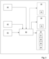
Figure 3 is a block diagram of the system according to the present invention, and -
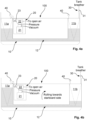
Figures 4a-c are principle drawings of different states of the fluid level in the side tanks of the U-tank. - Reference is now made to
Figure 1 which is a principle drawing of a U-tank active roll dampening system for avessel 100 according to the present invention. The U-tank 10 is formed by a pair ofside tanks 11a-b, one arranged on the starboard side of thevessel 100 and one arranged on port side of thevessel 100. Theside tanks 11a-b are sealed at upper end and are at lower end connected by acrossover duct 12, thus forming a U-tank 10 inside thevessel 100. The U-tank 10 will initially be filled with a fluid volume that is defined based on actual loading of thevessel 100. This configuration of a U-tank 10 is well known for a skilled person. Thecrossover duct 12 will be designed to allow sufficient flow of fluid between theside tanks 11a-b to counteract a part of the roll movement within natural roll period of thevessel 100. - The mentioned
side tanks 11a-b andcrossover duct 12 thus form a closed fluid system in thevessel 100. In the present invention the only connection between the twoside tanks 11a-b is thecrossover duct 12. - The present invention is related how to use this known U-tank for active roll dampening of the
vessel 100. - According to the present invention the system further comprises at least one vacuum and air
pressure manipulation unit 20 connected to upper part of one of an associatedside tank 11a-b, and anaeration device 30 connected to upper part of theother side tank 11a-b. In the shown example the vacuum and airpressure manipulation unit 20 is connected to theport side tank 11a and theaeration device 30 is connected to thestarboard side tank 11b, but the vacuum and airpressure manipulation unit 20 can be connected to thestarboard side tank 11b and theaeration device 30 to theport side tank 11a. - The vacuum and air
pressure manipulation unit 20 comprises at least one vacuum and airpressure generation unit 21 connected to a demand controlledventilation unit 22 connected to upper part of the interior of associatedside tank 11a via acontrollable valve 23. The vacuum and airpressure manipulation unit 20 is arranged to supply air pressure (overpressure) or vacuum (underpressure) on the fluid surface in the associatedside tank 11a. - The
aeration device 30 further comprises acontrollable valve 31 for controlling the aeration of the mentionedside tank 11b. - Reference is now made to
Figure 2 which is a principle drawing of a second embodiment of the U-tank active roll dampening system according to the present invention. In the second embodiment the at least one vacuum and airpressure manipulation unit 20 is in addition arranged to supply air pressure on fluid surface of theother side tank 11b via acontrollable valve 24 and apipe 25 extending from the pressure side of the vacuum and airpressure manipulation unit 20 to upper part of theother side tank 11b. In this embodiment there are further arrangedaeration devices 30 to both theside tanks 11a-b. This embodiment will be especially suitable for solutions where the fluid level difference between the twoside tanks 11a-b have to be larger than 5 meters, i.e. the fluid level in the associatedside tank 11a is to be higher than 5 meters above the fluid level in theother side tank 11b. In an alternative embodiment at least one separate air pressure unit is arranged to upper part of theside tank 11b to supply pressure to the fluid surface therein in the same manner as the vacuum and airpressure manipulation unit 20 as described above. - Accordingly, the system according to the present invention provides a U-tank active roll dampening system that can operate both in a passive mode and in an active mode for performing roll damping. By the system according to the present invention is achieved a system that provides full control of fluid moving between the two
side tanks 11a-b. - The system according to the present invention further comprises
fluid level sensors 40 arranged in theside tanks 11a-b for reading/measuring current fluid level in theside tanks 11a-b. - Reference is now made to
Figure 3 which is block diagram of a system according to the present invention. The system according to the present invention further comprises a dedicatedmotion reference unit 50 for measuring accelerations of thevessel 100 in a roll motion, hereunder providing roll angle for the vessel which can be used for controlling of the fluid level/volume in theside tanks 11a-b. - The system according to the present invention further comprises a
control unit 60 arranged for controlling the at least one airpressure manipulation unit 20, aeration device(s) 30 andvalves control unit 60 is provided with means and/or software for controlling the vacuum and airpressure manipulation unit 20, aeration device(s) 30, as well asvalves - In active mode the
control unit 60 is arranged to set theaeration device 30 of thestarboard side tank 11b open towards open air and the vacuum and airpressure manipulation unit 20 is set to supply air pressure or vacuum in theport side tank 11a based on measurement from themotion reference unit 50 and measurement of current fluid level in theside tanks 11a-b from thefluid level sensors 40. Accordingly, in active mode, instead of the fluid moving passively in relation to thevessel 100 motions and thus moving approximately 90 degrees behind the vessel roll motion, active control of the fluid movement is achieved by means of the system according to the present invention, and able to move the fluid in therespective side tanks 11a-b in anti-phase in front/advance of the vessel roll motion period. By means the vacuum and airpressure manipulation unit 20 capability of supplying air pressure or vacuum on the fluid surface in theport side tank 11a one can control the fluid to move between the mentionedside tanks 11a-b. With theaeration device 30 of thestarboard side tank 11b open against air and by supplying air pressure in theport side tank 11a the fluid level inport side tank 11a will be reduced by that the air pressure will force the fluid to move from theport side tank 11a via thecrossover duct 12 to thestarboard side tank 11b, thus correspondingly elevating the fluid level in thestarboard side tank 11b. Similarly, with theaeration device 30 of thestarboard side tank 11b open against air and by supplying vacuum to the fluid surface in theport side tank 11a, this will result in pressure difference between the mentionedside tanks 11a-b that will draw/force the fluid to move from thestarboard side tank 11b to theport side tank 11a via thecrossover duct 12, elevating the fluid level inport side tank 11a and reducing the fluid level in thestarboard side tank 11b. Accordingly, by controlling the pressure on the fluid surface in theport side tank 11a, full control of the fluid level in bothside tanks 11a-b, i.e. the entire U-tank is achieved in an active manner. - If a fluid difference of more than 5 meter is required, i.e. the fluid level in the
port side tank 11a will have to be larger than 5 meters above the fluid level in thestarboard side tank 11b, the above described second embodiment, as shown inFigure 2 , can be used in active mode. The second embodiment works as the first embodiment as described above, but when the fluid level difference of 5 meters is achieved, theaeration device 30 of theport side tank 11a is set open to air, while theaeration device 30 of thestarboard side tank 11b is closed and wherein the vacuum and airpressure manipulation unit 20 is set to supply air pressure on the fluid surface of thestarboard side tank 11b, whereupon the fluid level will further be lowered in thestarboard side tank 11b and correspondingly increased in theport side tank 11a. For most vessels a fluid level difference of 5 meters between theside tanks 11a-b will provide sufficient roll dampening, but for larger vessel there might be a need for larger fluid level difference which can be achieved by the second embodiment. - The second embodiment will further result in that one more rapid can achieve the required pressure difference in the two
side tanks 11a-b in a more rapid manner. - Accordingly, by measuring the accelerations of the
vessel 100 in a roll motion, this information can be used to move the fluid between theside tanks 11a-b, i.e. the fluid level in therespective side tanks 11a-b, in anti-phase in front/advance of the vessel roll motion period. Based on the measurements of themotion reference unit 50 thecontrol unit 60 can predict and calculate the fluid level in therespective side tanks 11a-b such that the fluid level/volume can be controlled to be in anti-phase in front/advance of the vessel roll motion period. Accordingly, instead of the waves executing a force to the vessel weight (tonnage) in a certain roll motion, the system according to the present invention supplies a sufficient amount of fluid in therespective side tanks 11a-b in correct anti-phase point in time in front of the roll motion period (frequency) of thevessel 100, i.e. optimally moving the fluid level in therespective side tanks 11a-b approximately 90 degrees in front/advance of the vessel roll period. - Accordingly, by the controlled fluid flow between the
side tanks 11a-b the affection from the waves on thevessel 100 can effectively be counteracted in an active manner by that the fluid is forced to flow fromside tank 11a-b toside tank 11a-b counteracting the vessels roll motion, which will reduce the vessels roll considerably. - The
control unit 60 is for this provided with means and/or software for software for controlling the fluid level in theside tanks 11a-b based on measurements by the dedicatedmotion reference unit 50 and measurements from thefluid level sensors 40 by calculating and provide optimal fluid level in theside tanks 11a-b. - By means of readings/measurements from the
motion reference unit 50 of the vessel accelerations, thecontrol unit 60 is arranged to calculate and provide optimal fluid level in theside tanks 11a-b based on input from a dedicatedmotion reference unit 50 measuring the vessel motion accelerations and in this way capable of setting the fluid level in anti-phase in front of the vessel roll period. - Accordingly, the
control unit 60 will be provided with means and/or software for using latest historical information from the dedicatedmotion reference unit 50 regarding roll motion of the vessel, and based on this predict probable future next roll motion/sequence and based on this control the fluid level in theside tanks 11a-b such that the fluid level is controlled in front/advance of the affection of the waves on the vessel. - The initial fluid volume inside the U-tank 10 must be defined by the crew based on the actual loading of the
vessel 100. - The present invention can utilize the same tank volumes as Anti-heeling systems already present on a vessel or the vessel can be provided with a U-tank according to the present invention.
- In addition to the above described active mode, the system according to the present invention can also be set in a passive mode. In passive mode the
control unit 60 will set the vacuum and airpressure manipulation unit 20 in aeration mode, where theport side tank 11a is set open towards air, and theaeration device 30 of thestarboard side tank 11b is set open towards air. Accordingly, in passive mode the fluid can flow freely (passively) between theside tanks 11a-b via thecrossover duct 12 according to the vessels minimum roll period, 90 degrees behind the roll motion period. If this period is to be extended, one can achieve this by controlling thevalves control unit 60. For the second embodiment also theaeration device 30 in theport side tank 11a can be used for this purpose. - The system according to the present invention can further be provided with a stabilization mode, wherein the
control unit 60 is arranged to close thevalve 23 of the airpressure manipulation unit 20 andvalve 31 of theaeration unit 30 instarboard side tank 11b locking the current fluid level in theside tanks 11a-b. In the second embodiment also theaeration device 30 of theport side tank 11a have to be closed. - The U-tank 10 of the present invention can further be arranged to a fluid supply and removal system for supply and removal of fluid in the U-tank 10, for changing the total fluid amount in the U-tank, which is well known in prior art and requires no further description herein.
- The system according to the present invention can further be provided with two or more vacuum and air
pressure manipulation units 20 andaeration devices 30, respectively, connected to the associatedside tanks 11a-b, respectively, for redundancy. The vacuum and airpressure manipulation unit 20 can further be provided with two or more vacuum and airpressure generation units 21 connected to the same demand controlledventilation unit 22 dimensioned for this. In an alternative embodiment the system can further comprise two or more vacuum and airpressure manipulation units 20 separately arranged to thesame side tank 11a viaseparate valves 23 or via thesame valve 23. - Reference is now made to
Figure 4a which show an initial state of fluid level in theside tanks 11a-b where the fluid level of in theport side tank 11a and thestarboard side tank 11b are levelled, for the first embodiment.Figure 4a could also represent a stabilized mode, where thevalves valves port side tank 11a andstarboard side tank 11b if desired. - Reference is now made to
Figure 4b which show a state, for the first embodiment of the system, where the fluid level inport side tank 11a is elevated in relation to the fluid level instarboard side tank 11b, by that the vacuum and airpressure manipulation unit 20 supplies a vacuum on the fluid surface of the fluid in theport side tank 11a, resulting in a pressure difference between theside tanks 11a-b resulting in that fluid flows from thestarboard tank 11b and into theport side tank 11a, and thus compensating for roll movements caused by a wave hitting on port side or a wave passing from starboard side. - Reference is now made to
Figure 4c which show a state, for the first embodiment of the system, where the fluid level instarboard side tank 11b is elevated in relation to the fluid level inport side tank 11a, by that the vacuum and airpressure manipulation unit 20 supplies pressure on the fluid surface of theport side tank 11a forcing the fluid to flow to thestarboard side tank 11b, reducing the fluid level in theport side tank 11a and elevating the fluid level in thestarboard side tank 11b, and thus compensating for roll movement caused by a wave hitting on starboard side or a wave passing from port side. - Accordingly, by the present invention is achieved a system where the fluid level in the
respective side tanks 11a-b are set to be in anti-phase in front/advance of the vessel roll motion period, and optimally approximately 90 degrees in front/advance of roll motion period. The fluid level difference between theside tanks 11a-b will return to levelled with almost none use of energy due to the pressure difference between theside tanks 11a-b. Accordingly, the vacuum and airpressure manipulation unit 20 will only require power consumption for half of the required pressure difference, as the first half of the pressure difference can be achieved with the vacuum and airpressure manipulation unit 20 in idle running. - Further, by using air pressure and vacuum in only one of the side tanks for controlling the fluid level in both of the
side tanks 11a-b this will results in only approx. 50 % power requirement compared to prior art systems, as the present invention will utilize the fluid height difference and will only have to perform half the work for moving the fluid volume from oneside tank 11a-b to theother side tank 11a-b due to the use of the combination of pressure and vacuum. - The shape and volume of the
side tanks 11a-b will have to be adapted the actual properties of vessel. Further, it will an advantage, that the tanks have large volume and that the system can operate with low pressure differences.
Claims (12)
- U-tank active roll dampening system for vessel (100), wherein the U-tank (10) is formed by side tanks (11a-b), one arranged at port side of the vessel (100) and one arranged at starboard side of the vessel (100), the side tanks (11a-b) at upper end sealed and at lower end connected by a crossover duct (12), wherein the U-tank (10) is partly filled with a fluid, the system comprising a motion reference unit (50) measuring accelerations of the vessel (100) roll motion and a control unit (60), characterized in that at least one vacuum and air pressure manipulation unit (20) is arranged to upper part of an associated side tank (11a-b) and at least one aeration device (30) against open air is connected to upper part of the other side tank (11a-b), wherein the at least one vacuum and air pressure manipulation unit (20) is arranged to supply air pressure or vacuum on the fluid surface in the associated side tank (11a), wherein the control unit (60) is provided with means and/or software for controlling the at least one vacuum and air pressure manipulation unit (20) to control fluid level in both side tanks (11a-b) in anti-phase in front/advance of vessel roll motion period by predicting and calculating the fluid level in the respective side tanks (11a-b) in anti-phase in front/advance of vessel roll motion period based on measurements of the motion reference unit (50).
- U-tank active roll dampening system for vessel (100) according to claim 1, characterized in that the vacuum and air pressure manipulation unit (20) is provided with a valve (23) for opening or closing the connection to the associated side tank (11a-b) and the aeration device (30) is provided with a valve (31) for opening or closing the aeration to open air.
- U-tank active roll dampening system for vessel (100) according to claim 1, characterized in that the vacuum and air pressure manipulation unit (20) is arranged for aeration against open air of the associated side tank (11a-b).
- U-tank active roll dampening system for vessel (100) according to claim 1, characterized in that the system comprises at least one fluid level sensor (40) arranged in each of the side tanks (11a-b) for measuring the fluid level in the respective side tank (11a-b).
- U-tank active roll dampening system for vessel (100) according to any one of the preceding claims, characterized in that the at least one vacuum and air pressure manipulation unit (20) is arranged to supply air pressure on the fluid surface of the other side tank (11a-b) or that at least one separate air pressure unit is arranged to supply pressure on the fluid surface of the other side tank (11a-b), and that aeration devices (30) provided with controllable valves (31) for opening or closing the aeration to open air are arranged to both side tanks (11a-b).
- U-tank active roll dampening system for vessel according to claim 5, characterized in that the at least one vacuum and air pressure manipulation unit (20) is arranged to the other side tank (11a-b) via a controllable valve (24) and a pipe (25) extending from pressure side of the vacuum and air pressure manipulation unit (20) to upper part of the other side tank (11a-b).
- U-tank active roll dampening system for vessel (100) according to claim 1, characterized in that the dedicated motion reference unit (50) measures accelerations of the vessel (100) in a roll motion.
- U-tank active roll dampening system for vessel (100) according to claims 1 or 2, characterized in that the control unit (60) further is controlling the aeration device(s) (30) and valves (23, 31,24).
- U-tank active roll dampening system for vessel (100) according to any one of the preceding claims, characterized in that the vacuum and air pressure manipulation unit (20) comprises at least one vacuum and air pressure generation unit (21) connected to a demand controlled ventilation unit (22).
- Method for active roll dampening of a vessel (100) provided with a U-tank (10) formed by side tanks (11a-b), one arranged at port side of the vessel (100) and one arranged at starboard side of the vessel (100), the side tanks (11a-b) at upper end sealed and at lower end connected by a crossover duct (12), wherein the U-tank (10) is partly filled with a fluid, characterized bymeasuring accelerations of the vessel (100) roll motion, predicting and calculating the fluid level in both side tanks (11a-b) in anti-phase in front/advance of vessel roll motion period based on the measurements, andcontrolling fluid level in both the side tanks (11a-b) in anti-phase in front/advance of vessel roll motion period by supplying air pressure or vacuum by means of at least one vacuum and air pressure manipulation unit (20) on fluid surface in an associated side tank (11a-b) and aeration against open air of the other side tank (11a-b) by means of an aeration device (30).
- Method according to claim 10, characterized by controlling the fluid level in the side tanks (11a-b) based on measurements by a dedicated motion reference unit (50) and measurements from the fluid level sensors (40) associated with the side tanks (11a-b) so as to control the fluid level in the respective side tank (11a-b) in anti-phase in front/advance of vessel roll motion period, approximately 90 degrees in front/advance of the vessel roll motion period.
- Method according to claims 10-11, characterized by closing the aeration of the other side tank (11a-b) and opening for aeration of the side tank (11a-b) associated with the at least one vacuum and air pressure manipulation unit (20) by means of at least one aeration device (30) arranged thereto, and supplying air pressure utilizing the at least one vacuum and air pressure manipulation unit (20) or at least one separate air pressure unit on fluid surface of the other side tank (11a-b) when additional increasing of the fluid level in the side tank (11a-b) associated with the vacuum and air pressure manipulation unit (20) is required.
Applications Claiming Priority (2)
| Application Number | Priority Date | Filing Date | Title |
|---|---|---|---|
| NO20180092A NO344388B1 (en) | 2018-01-19 | 2018-01-19 | U-tank active roll dampening system for and method for active roll dampening of a vessel |
| PCT/NO2019/050011 WO2019143257A1 (en) | 2018-01-19 | 2019-01-18 | U-tank active roll dampening system for and method for active roll dampening of a vessel |
Publications (3)
| Publication Number | Publication Date |
|---|---|
| EP3740424A1 EP3740424A1 (en) | 2020-11-25 |
| EP3740424A4 EP3740424A4 (en) | 2021-11-24 |
| EP3740424B1 true EP3740424B1 (en) | 2024-05-01 |
Family
ID=67301541
Family Applications (1)
| Application Number | Title | Priority Date | Filing Date |
|---|---|---|---|
| EP19741270.3A Active EP3740424B1 (en) | 2018-01-19 | 2019-01-18 | U-tank active roll dampening system for and method for active roll dampening of a vessel |
Country Status (6)
| Country | Link |
|---|---|
| US (1) | US11299242B2 (en) |
| EP (1) | EP3740424B1 (en) |
| CN (1) | CN110753658B (en) |
| BR (1) | BR112020013386A2 (en) |
| NO (1) | NO344388B1 (en) |
| WO (1) | WO2019143257A1 (en) |
Families Citing this family (4)
| Publication number | Priority date | Publication date | Assignee | Title |
|---|---|---|---|---|
| CN112278161B (en) * | 2020-11-03 | 2021-08-10 | 江苏科技大学 | Active pitching device, pitching system and working method of LNG cargo ship |
| CN112389598A (en) * | 2020-11-20 | 2021-02-23 | 中海石油气电集团有限责任公司 | Towing attitude control method suitable for unpowered FLNG/FSRU |
| CN114560053A (en) * | 2022-04-08 | 2022-05-31 | 交通运输部天津水运工程科学研究所 | Marine air compression anti-rolling device |
| CN115107946A (en) * | 2022-08-04 | 2022-09-27 | 上海船舶研究设计院(中国船舶工业集团公司第六0四研究院) | Active roll reduction method for offshore floating platform |
Family Cites Families (18)
| Publication number | Priority date | Publication date | Assignee | Title |
|---|---|---|---|---|
| GB408796A (en) * | 1932-04-11 | 1934-04-19 | Nicolai Minorsky | Improvements in anti-rolling tank systems for ships and other craft |
| GB419028A (en) * | 1933-03-29 | 1934-11-05 | Siemens App Und Maschinen Gmbh | Stabilization of ships by means of liquid-filled tanks |
| DE1277060B (en) * | 1966-10-13 | 1968-09-05 | Licentia Gmbh | Device for changing the liquid level in the tank space of tank stabilization systems |
| GB1213853A (en) | 1968-02-02 | 1970-11-25 | Muirhead Ltd | Improvements in and relating to ship stabilizers |
| FR2053697A5 (en) * | 1969-07-15 | 1971-04-16 | Polouektoff Jean Paul | |
| DE2338557A1 (en) * | 1973-07-30 | 1975-02-20 | Ulf Dipl Ing Palm | Anti-rolling tank to dampen ships movements - uses identical vacuum-tight end chambers linked by liquid contg. lower pipe |
| DE2508748A1 (en) * | 1975-02-28 | 1976-09-09 | Horst Dipl Ing Halden | INCLINATION COMPENSATION SYSTEM OF SHIPS WITH CONTROL VALVE ARRANGEMENT |
| GB2087818A (en) * | 1980-11-25 | 1982-06-03 | Vickers Ltd | Tank fluid transfer device |
| US4864958A (en) | 1987-09-25 | 1989-09-12 | Belinsky Sidney I | Swap type floating platforms |
| DE10045921A1 (en) * | 2000-09-16 | 2002-03-28 | Intering Interferenztechnik In | Ship anti-roll system has liquid containers on each side of the hull, with a connecting line to transfer liquid from one to the other, and a connecting line to transfer compressed air between the containers |
| DE10315294B4 (en) * | 2003-04-04 | 2006-09-28 | Dallach, Gert, Dr. Ing. | Roll damping system for ships |
| NO333766B1 (en) * | 2007-12-07 | 2013-09-16 | Marine Roll & Pitch Control As | System and method for active and passive stabilization of vessel |
| CN101624087B (en) * | 2008-07-11 | 2011-12-21 | 中国船舶重工集团公司第七○四研究所 | Anti-rolling tank control device |
| NO332151B1 (en) * | 2009-08-06 | 2012-07-09 | Eirik Hellesvik | Rulledempningstank |
| KR101235329B1 (en) * | 2009-12-24 | 2013-02-19 | 울산대학교 산학협력단 | Stabilizing apparatus of ship using anti-rolling tank |
| CN102910264B (en) * | 2012-10-09 | 2015-09-30 | 哈尔滨工程大学 | A kind of antirolling apparatus of ship mooring state |
| KR101541063B1 (en) * | 2013-10-18 | 2015-07-31 | 삼성중공업 주식회사 | Anti-heeling device and method for ship |
| KR101690924B1 (en) * | 2015-02-27 | 2016-12-29 | 삼성중공업 주식회사 | Ballast system |
-
2018
- 2018-01-19 NO NO20180092A patent/NO344388B1/en unknown
-
2019
- 2019-01-18 CN CN201980003079.4A patent/CN110753658B/en active Active
- 2019-01-18 BR BR112020013386-8A patent/BR112020013386A2/en unknown
- 2019-01-18 US US16/959,194 patent/US11299242B2/en active Active
- 2019-01-18 WO PCT/NO2019/050011 patent/WO2019143257A1/en active Search and Examination
- 2019-01-18 EP EP19741270.3A patent/EP3740424B1/en active Active
Also Published As
| Publication number | Publication date |
|---|---|
| CN110753658B (en) | 2022-11-18 |
| EP3740424A1 (en) | 2020-11-25 |
| US11299242B2 (en) | 2022-04-12 |
| NO20180092A1 (en) | 2019-07-22 |
| CN110753658A (en) | 2020-02-04 |
| EP3740424A4 (en) | 2021-11-24 |
| BR112020013386A2 (en) | 2020-12-01 |
| NO344388B1 (en) | 2019-11-25 |
| WO2019143257A1 (en) | 2019-07-25 |
| US20200398950A1 (en) | 2020-12-24 |
Similar Documents
| Publication | Publication Date | Title |
|---|---|---|
| EP3740424B1 (en) | U-tank active roll dampening system for and method for active roll dampening of a vessel | |
| US8479674B2 (en) | System and method for the active and passive stabilization of a vessel | |
| US7370594B2 (en) | System for reducing the roll of a boat | |
| CN103434616B (en) | A kind of underwater buoyant body and installation method thereof | |
| CN109466711A (en) | A kind of drop damps the tank stabilizer in period capable of automatic changing | |
| KR101731966B1 (en) | a system for preventing a rolling motion of ship, a method thereof and a ship including it | |
| KR20110139870A (en) | Anti-heeling system using gravity | |
| KR101964836B1 (en) | Anti-rolling apparatus | |
| CN105667725B (en) | Semi-submersible type construction platform | |
| CN115107946A (en) | Active roll reduction method for offshore floating platform | |
| KR20110015277A (en) | Stabilizer for floating body | |
| WO2011074926A4 (en) | Twin-hulled lng floater | |
| JPH1024894A (en) | Method for changing draft of ship | |
| CN209336964U (en) | A kind of tank stabilizer device | |
| CN117646451B (en) | Open caisson floating transportation anti-rolling device and control method thereof | |
| CN219948513U (en) | Anti-transverse-tilting system of container ship | |
| KR20150021373A (en) | Anti-heeling system of ship having anti-rolling function | |
| CN114701614A (en) | Intelligent stabilizing system for large ship | |
| KR20140067682A (en) | Anti-rolling tank of the stand alone type | |
| KR102347318B1 (en) | System for stabilizing vessel having anti-rolling and anti-heeling function and vessel including the same | |
| KR20120084385A (en) | Control method using pressure sensor for air supply to air-cavity of air-cavity vessel | |
| CN219927938U (en) | Offshore comprehensive positioning device of drilling and production ship | |
| KR20110017119A (en) | Ballast system of a vessel | |
| RU2657095C1 (en) | Vessel | |
| JPH01226488A (en) | Ballast regulator for floating body such as vessel |
Legal Events
| Date | Code | Title | Description |
|---|---|---|---|
| STAA | Information on the status of an ep patent application or granted ep patent |
Free format text: STATUS: THE INTERNATIONAL PUBLICATION HAS BEEN MADE |
|
| PUAI | Public reference made under article 153(3) epc to a published international application that has entered the european phase |
Free format text: ORIGINAL CODE: 0009012 |
|
| STAA | Information on the status of an ep patent application or granted ep patent |
Free format text: STATUS: REQUEST FOR EXAMINATION WAS MADE |
|
| 17P | Request for examination filed |
Effective date: 20200811 |
|
| AK | Designated contracting states |
Kind code of ref document: A1 Designated state(s): AL AT BE BG CH CY CZ DE DK EE ES FI FR GB GR HR HU IE IS IT LI LT LU LV MC MK MT NL NO PL PT RO RS SE SI SK SM TR |
|
| AX | Request for extension of the european patent |
Extension state: BA ME |
|
| DAV | Request for validation of the european patent (deleted) | ||
| DAX | Request for extension of the european patent (deleted) | ||
| A4 | Supplementary search report drawn up and despatched |
Effective date: 20211025 |
|
| RIC1 | Information provided on ipc code assigned before grant |
Ipc: B63B 39/03 20060101AFI20211019BHEP |
|
| P01 | Opt-out of the competence of the unified patent court (upc) registered |
Effective date: 20230526 |
|
| GRAP | Despatch of communication of intention to grant a patent |
Free format text: ORIGINAL CODE: EPIDOSNIGR1 |
|
| STAA | Information on the status of an ep patent application or granted ep patent |
Free format text: STATUS: GRANT OF PATENT IS INTENDED |
|
| INTG | Intention to grant announced |
Effective date: 20231206 |
|
| GRAS | Grant fee paid |
Free format text: ORIGINAL CODE: EPIDOSNIGR3 |
|
| GRAA | (expected) grant |
Free format text: ORIGINAL CODE: 0009210 |
|
| STAA | Information on the status of an ep patent application or granted ep patent |
Free format text: STATUS: THE PATENT HAS BEEN GRANTED |
|
| AK | Designated contracting states |
Kind code of ref document: B1 Designated state(s): AL AT BE BG CH CY CZ DE DK EE ES FI FR GB GR HR HU IE IS IT LI LT LU LV MC MK MT NL NO PL PT RO RS SE SI SK SM TR |
|
| REG | Reference to a national code |
Ref country code: GB Ref legal event code: FG4D |