EP3740404B1 - Cleaning apparatus for cleaning a transparent front element of an optical sensor for a motor vehicle, as well as assembly - Google Patents
Cleaning apparatus for cleaning a transparent front element of an optical sensor for a motor vehicle, as well as assembly Download PDFInfo
- Publication number
- EP3740404B1 EP3740404B1 EP19700897.2A EP19700897A EP3740404B1 EP 3740404 B1 EP3740404 B1 EP 3740404B1 EP 19700897 A EP19700897 A EP 19700897A EP 3740404 B1 EP3740404 B1 EP 3740404B1
- Authority
- EP
- European Patent Office
- Prior art keywords
- cleaning
- cleaning apparatus
- front element
- contamination
- information
- Prior art date
- Legal status (The legal status is an assumption and is not a legal conclusion. Google has not performed a legal analysis and makes no representation as to the accuracy of the status listed.)
- Active
Links
Images

Classifications
-
- B—PERFORMING OPERATIONS; TRANSPORTING
- B60—VEHICLES IN GENERAL
- B60S—SERVICING, CLEANING, REPAIRING, SUPPORTING, LIFTING, OR MANOEUVRING OF VEHICLES, NOT OTHERWISE PROVIDED FOR
- B60S1/00—Cleaning of vehicles
- B60S1/02—Cleaning windscreens, windows or optical devices
- B60S1/46—Cleaning windscreens, windows or optical devices using liquid; Windscreen washers
- B60S1/48—Liquid supply therefor
- B60S1/52—Arrangement of nozzles; Liquid spreading means
-
- B—PERFORMING OPERATIONS; TRANSPORTING
- B60—VEHICLES IN GENERAL
- B60S—SERVICING, CLEANING, REPAIRING, SUPPORTING, LIFTING, OR MANOEUVRING OF VEHICLES, NOT OTHERWISE PROVIDED FOR
- B60S1/00—Cleaning of vehicles
- B60S1/02—Cleaning windscreens, windows or optical devices
- B60S1/56—Cleaning windscreens, windows or optical devices specially adapted for cleaning other parts or devices than front windows or windscreens
-
- B—PERFORMING OPERATIONS; TRANSPORTING
- B08—CLEANING
- B08B—CLEANING IN GENERAL; PREVENTION OF FOULING IN GENERAL
- B08B3/00—Cleaning by methods involving the use or presence of liquid or steam
- B08B3/04—Cleaning involving contact with liquid
- B08B3/10—Cleaning involving contact with liquid with additional treatment of the liquid or of the object being cleaned, e.g. by heat, by electricity or by vibration
- B08B3/12—Cleaning involving contact with liquid with additional treatment of the liquid or of the object being cleaned, e.g. by heat, by electricity or by vibration by sonic or ultrasonic vibrations
-
- B—PERFORMING OPERATIONS; TRANSPORTING
- B60—VEHICLES IN GENERAL
- B60Q—ARRANGEMENT OF SIGNALLING OR LIGHTING DEVICES, THE MOUNTING OR SUPPORTING THEREOF OR CIRCUITS THEREFOR, FOR VEHICLES IN GENERAL
- B60Q1/00—Arrangement of optical signalling or lighting devices, the mounting or supporting thereof or circuits therefor
- B60Q1/02—Arrangement of optical signalling or lighting devices, the mounting or supporting thereof or circuits therefor the devices being primarily intended to illuminate the way ahead or to illuminate other areas of way or environments
-
- B—PERFORMING OPERATIONS; TRANSPORTING
- B60—VEHICLES IN GENERAL
- B60S—SERVICING, CLEANING, REPAIRING, SUPPORTING, LIFTING, OR MANOEUVRING OF VEHICLES, NOT OTHERWISE PROVIDED FOR
- B60S1/00—Cleaning of vehicles
- B60S1/02—Cleaning windscreens, windows or optical devices
- B60S1/46—Cleaning windscreens, windows or optical devices using liquid; Windscreen washers
-
- B—PERFORMING OPERATIONS; TRANSPORTING
- B60—VEHICLES IN GENERAL
- B60S—SERVICING, CLEANING, REPAIRING, SUPPORTING, LIFTING, OR MANOEUVRING OF VEHICLES, NOT OTHERWISE PROVIDED FOR
- B60S1/00—Cleaning of vehicles
- B60S1/02—Cleaning windscreens, windows or optical devices
- B60S1/54—Cleaning windscreens, windows or optical devices using gas, e.g. hot air
-
- G—PHYSICS
- G01—MEASURING; TESTING
- G01N—INVESTIGATING OR ANALYSING MATERIALS BY DETERMINING THEIR CHEMICAL OR PHYSICAL PROPERTIES
- G01N21/00—Investigating or analysing materials by the use of optical means, i.e. using sub-millimetre waves, infrared, visible or ultraviolet light
- G01N21/84—Systems specially adapted for particular applications
- G01N21/88—Investigating the presence of flaws or contamination
- G01N21/94—Investigating contamination, e.g. dust
-
- H—ELECTRICITY
- H04—ELECTRIC COMMUNICATION TECHNIQUE
- H04N—PICTORIAL COMMUNICATION, e.g. TELEVISION
- H04N23/00—Cameras or camera modules comprising electronic image sensors; Control thereof
- H04N23/80—Camera processing pipelines; Components thereof
- H04N23/81—Camera processing pipelines; Components thereof for suppressing or minimising disturbance in the image signal generation
- H04N23/811—Camera processing pipelines; Components thereof for suppressing or minimising disturbance in the image signal generation by dust removal, e.g. from surfaces of the image sensor or processing of the image signal output by the electronic image sensor
Definitions
- the invention relates to a cleaning apparatus for cleaning a transparent front element of an optical sensor for a motor vehicle. Further, the invention relates to an assembly.
- detector devices for receiving light beams for motor vehicles are already known. They comprise a transparent front element.
- contaminations on the transparent front element can therein occur. Impairment of the received information by the detector device can occur by the contamination.
- cleaning of the transparent front element is required.
- a contamination is for example performed by manually activating a liquid and/or air cleaning system.
- WO 2012/065952 A1 discloses a method for validating or verifying a cleaning process of a surface, which is contaminated with at least one chemical substrate.
- US 2016/311405 A1 discloses the preamble of claim 1.
- An aspect of the invention relates to a cleaning apparatus for cleaning a transparent front element of an optical sensor of a camera for a motor vehicle.
- the cleaning apparatus comprises the transparent front element and a light source for externally illuminating the front element with light beams. Further, the cleaning apparatus comprises a detector device for receiving the light beams passed through the front element. Furthermore, the cleaning apparatus comprises an evaluation device, which is formed for evaluating the light beams received by the detector device for determining a degree of contamination of the front element. Depending on the evaluation, a control signal for a cleaning device of the cleaning apparatus can be generated such that the front element is cleanable by means of the cleaning device.
- the degree of contamination can be accurately captured and then the control signal for cleaning the transparent front element can be correspondingly performed depending on the respective degree of contamination.
- light beams for the optical sensor can arrive at the optical sensor, for example at an image sensor of the optical sensor, in improved manner, whereby improved operation of the optical sensor is allowed.
- impairment in particular does not occur at the optical sensor since the transparent front element is cleaned in improved manner.
- the transparent front element can be purposefully cleaned.
- the cleaning signal for the cleaning device is not generated.
- a cleaning medium can for example be saved.
- the transparent front element should be contaminated, thus, the transparent front element can be correspondingly purposefully cleaned.
- further external illumination of the front element can be performed to check the cleaning of the front element and optionally, if a contamination should for example further be recognized, to be able to again perform a cleaning process.
- At least the cleaning device can be mounted displaceably relative with respect to the front element, in particular mounted on a telescopic arm, and/or the light source and the cleaning device can be disposed in a common housing.
- the cleaning device By mounting the cleaning device on a telescopic arm, it is in particular allowed that improved aerodynamics of the motor vehicle can be realized since the cleaning device in particular does for example not protrude from a trim part of the motor vehicle if it should not be actuated.
- the telescopic arm with the cleaning device can then for example extend from the trim part and perform the cleaning of the front element.
- the light source and the cleaning device are disposed in a common housing.
- the light source and the cleaning device can then be disposed within the one housing in material and space saving manner.
- the light source and the cleaning device can be formed as a common component.
- the detector device is disposed in the common housing with the light source and/or the cleaning device. Thereby, it is allowed that determination of the degree of contamination can yet be captured with a severe contamination of the front element even if light beams no longer get through the transparent front element.
- the cleaning apparatus is formed for generating ultrasonic waves, wherein the front element is cleanable by means of the ultrasonic waves. It is in particular possible that the ultrasonic waves are exerted on the contamination correspondingly long in time depending on the degree of contamination such that the contamination can be advantageously removed. Further, the ultrasonic waves can be emitted with different wavelengths such that a more advantageous cleaning of the front element can be performed.
- the cleaning device comprises a liquid cleaning medium, which is stored in a cleaning reservoir, and the liquid cleaning medium can be sprayed onto the front element via a cleaning nozzle of the cleaning device such that the front element is cleanable by means of the cleaning medium.
- the cleaning reservoir can for example be a cleaning reservoir of the cleaning apparatus, however, it is also possible that it is for example resorted to reservoirs already installed in the motor vehicle such that the cleaning medium of a windscreen wiping device is for example used and thus it can be resorted to the cleaning reservoir of the windscreen wiping device. Thereby, reliable cleaning of the front element can in particular be allowed. Furthermore, the cleaning can for example be performed without additional reservoir since it can be resorted to systems already installed in the motor vehicle.
- the cleaning apparatus comprises an air pressure nozzle, by means of which an air jet can be generated, which can be jetted to the front element, whereby the front element is cleanable.
- an air pressure nozzle by means of which an air jet can be generated, which can be jetted to the front element, whereby the front element is cleanable.
- the degree of contamination can be determinable depending on at least one received wavelength of the light beams and/or a contamination material and/or a contamination intensity can be determinable as the degree of contamination by means of the evaluation device, and the control signal can be generable at least depending on the contamination material and/or the contamination intensity. Since in particular different contamination materials and different contamination intensities, respectively, exert a different influence on the emitted wavelength by the light source and the received wavelength of the light beams, reliable determination of the degree of contamination in particular as a contamination material and/or as a contamination intensity can be determinable by means of this method. Thus, the degree of contamination can be determined in detailed manner and the control signal can be correspondingly generated. Thereby, advantageous cleaning of the front element can be performed.
- the light beams are received by means of the detector unit and compared by means of reference light beams. Thereby, the degree of contamination can be reliably determined.
- the invention further includes the light source comprising at least two light emitting diodes, wherein light beams with a first wavelength can be emitted by a first light emitting diode and light beams with a second wavelength different from the first wavelength can be emitted by at least one second light emitting diode.
- the wavelengths of the at least two light emitting diodes are in a range not visible to the human eye.
- the wavelengths can be ultraviolet or infrared radiation.
- visible light beams are emitted.
- light beams with a higher wavelength than infrared can be emitted.
- a combination of different light beams can be emitted.
- the detector unit and the transparent front element can in particular allow transmission and detection of the corresponding wavelengths.
- this can be allowed by a standard silicon image sensor with filters with corresponding wavelengths or with corresponding combinations for receiving units, which are disposed in the image sensor.
- the light source comprises a plurality of light emitting diodes, which each emit light beams with different wavelength such that a reliable evaluation can be performed.
- At least information of an environment of the front element can be able to be taken into account in the evaluation of the received light beams.
- improved calibration of the detector unit can be performed since the environmental light beams are known and can then for example be correspondingly subtracted from the reference light beams, to which they are compared, such that only the light beams emitted by the light source are taken into account in the evaluation of the degree of contamination.
- the cleaning apparatus is formed for receiving information, which relates to reception of light beams by an image sensor of the optical sensor, wherein the evaluation device is formed to take into account this information in the evaluation for the determination of the degree of contamination of the front element.
- a camera can for example serve as the optical sensor. Then, the captured information by the image sensor of the camera can be taken into account in the evaluation.
- only the image sensor of the optical sensor can be used for evaluation by the evaluation device of the cleaning apparatus. Thereby, the cleaning apparatus can still reliably determine the degree of contamination in particular reduced in components and thereby perform a reliable cleaning of the transparent front element.
- the cleaning apparatus comprises a communication device for bidirectional communication of information with at least one information device disposed externally to the cleaning apparatus, wherein information received from the information device can be taken into account in the evaluation by the evaluation device.
- information of a vehicle-to-infrastructure can be taken into account in the evaluation.
- information of a vehicle-to-vehicle structure can be taken into account in the evaluation.
- the vehicle-to-infrastructure information and the vehicle-to-vehicle information, respectively can be weighted, for example with respect to the input time, and then be incorporated in the evaluation.
- the vehicle-to-infrastructure information can for example be Cloud-based information.
- other vehicles for example also obtain the information of the evaluation device and it is taken into account in a cleaning process in for example optical sensors of the further motor vehicles.
- the further vehicles for example do not have to comprise a cleaning apparatus according to the invention, but only the corresponding cleaning device to be able to perform cleaning.
- the corresponding information about the cleaning process can be provided by the motor vehicle with the cleaning apparatus according to the invention.
- a plurality of control signals is generable by the evaluation device for the cleaning device.
- the cleaning device should for example comprise an air pressure nozzle and a cleaning nozzle
- a cleaning cycle can in particular be performed depending on the degree of contamination and in particular depending on the contamination intensity and the contamination material.
- cleaning can then first be performed by means of the air pressure nozzle and subsequently by means of the cleaning nozzle.
- a possible combination of any proposed cleaning methods in other words, by means of ultrasound, by means of the cleaning medium and by means of the air pressure nozzle, is also possible. It is also possible that the corresponding cleaning process can be performed multiple times.
- the information about for example a successful cleaning process is stored in a storage device of the motor vehicle such that it is available in the future.
- This stored information can for example also be provided for a car wash such that the motor vehicle provides this information to the car wash upon entry in the car wash such that it is for example informed about the degree of contamination and thereby about the contamination intensity and the contamination material such that a particularly preferred program can be automatically selected in the car wash.
- the motor vehicle has an at least similar contamination state as the transparent front element, thus, improved cleaning of the motor vehicle can be able to be performed.
- the cleaning apparatus can for example also be formed in a screen wiping system for cleaning vehicle panes or windscreens.
- the cleaning apparatus is accommodated in a drone and the drone for example flies to a motor vehicle and determines the degree of contamination.
- the drone can then fly from optical sensor to optical sensor and check the cleaning by means of the optical sensor.
- a further aspect relates to an assembly with a camera and with a cleaning apparatus according to any one of above mentioned aspects.
- information of an image sensor of the camera can be receivable by the cleaning apparatus, wherein the received information of the image sensor can be taken into account in the evaluation by the evaluation device for determining the degree of contamination.
- the image sensor of the camera is additionally or alternatively used as the detector device.
- a still further aspect of the invention relates to a motor vehicle with a cleaning apparatus or with an assembly.
- the motor vehicle is formed as a passenger car.
- Advantageous forms of configuration of the cleaning apparatus are to be regarded as advantageous forms of configuration of the assembly and of the motor vehicle, respectively.
- Fig. 1 shows a motor vehicle 1 according to an embodiment of the present invention in a top view.
- the motor vehicle 1 is formed as a passenger car.
- the motor vehicle 1 comprises a camera system 2.
- the camera system 2 in turn comprises an image processing device 3, which can for example be constituted by an electronic controller of the motor vehicle 1.
- the camera system 2 comprises at least one camera 4.
- the camera system 2 for example comprises four cameras 4, which are disposed distributed at the motor vehicle 1. However, only two cameras 4 or three cameras 4 or else more than four cameras 4 can for example also be provided.
- one of the cameras 4 is disposed in a rear area 5
- one of the cameras 4 is disposed in a front area 7 of the motor vehicle 1 and the remaining two cameras 4 are disposed in a respective lateral area 6, in particular in an area of the wing mirrors.
- the number and arrangement of the cameras 4 of the camera system 2 are to be purely exemplarily understood.
- An object OB in an environment 8 of the motor vehicle 1 can be captured by the cameras 4.
- the four cameras 4 are formed identical in construction.
- a sequence of images can be provided by the cameras 4, which describe the environment 8.
- These images can be transmitted from the cameras 4 to the image processing device 3.
- the camera system 2 serves for assisting the driver of the motor vehicle 1 in driving the motor vehicle 1.
- the camera system 2 can for example be a so-called electronic rearview mirror (then it preferably comprises two cameras 4 in the lateral areas 6) or an ACC system (Adaptive Cruise Control system) or a parking assistance system or other system. It can also be formed in the motor vehicle interior for capturing a person, in particular a vehicle driver.
- the motor vehicle 1 comprises a cleaning apparatus 9.
- the motor vehicle 1 can comprise an assembly 32, which comprises at least one camera 4 as an optical sensor and at least one cleaning apparatus 9.
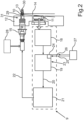
- Fig. 2 shows a schematic view of an embodiment of the cleaning apparatus 9.
- the cleaning apparatus 9 comprises a cleaning device 10 and a transparent front element 11.
- the cleaning device 10 and the transparent front element 11 are disposed at a trim part 12 of the motor vehicle 1 in the present embodiment.
- the transparent front element 11 is for example a lens of the camera 4.
- the cleaning device 10 comprises a light source 13, which emits light beams 14 for externally illuminating the front element 11.
- the light source 13 and the cleaning device 10 are formed in a common housing 15.
- a lens of the light source 13 and light emitting diodes 16, 17 ( Fig. 4 ) of the light source 13 are formed as multi-array LEDS in order to be able to perform downsizing of the cleaning device 10. It can be provided that the light emitting diodes 16, 17 are wired or have been produced by means of a flexible circuit board, a standard circuit board or by means of another injection molding method.
- a detector device 18 of the cleaning apparatus 9 is formed for receiving the light beams 14 passing through the front element 11. It can be provided that the detector device 18 is formed as an image sensor of the camera 4. The detector device 18 in turn is coupled to an evaluation device 19, which in particular can perform a determination of the degree of contamination of the front element 11.
- the detector device 18 which can for example be formed as an image sensor of the camera 4, performs both the image processing for the camera 4 and the detection for the cleaning apparatus 9.
- light beams 14 in the ultraviolet range, in the range visible to the human eye, infrared range or in an even higher wavelength range can be detected by means of the detector device 18.
- the degree of contamination can in particular be determinable by means of the evaluation device 19.
- a contamination material and/or a contamination intensity are determinable as the degree of contamination and a control signal 20 for a control device 21 can be generable depending on the degree of contamination such that a control signal 22 for the cleaning device 10 is reliably generable.
- At least information 23 of an environment of the front element 11 can in particular be taken into account.
- This information 23 can in particular for example be environmental light beams such that they can be taken into account in the analysis.
- the cleaning apparatus 9 can comprise a communication device 24, which is formed for bidirectional communication 25, 26 of information with at least one information device 27 disposed externally to the cleaning apparatus 9, wherein information 25 received from the information device 27 can be taken into account in the evaluation by the evaluation device 19.
- the information device 27 in turn can for example be formed as a part of a vehicle-to-infrastructure and vehicle-to-vehicle information device, respectively.
- data can for example be exchanged in Cloud-based manner such that the cleaning apparatus 9 can obtain received information 25 from this Cloud.
- the information device 27 can be formed as a part of a further motor vehicle and the evaluation device 19 can for example send the processed information about the environment, in particular about the degree of contamination, to the information device 27 such that for example further motor vehicles, which in particular do not comprise a cleaning apparatus 9 according to the invention, obtain the information such that a corresponding cleaning can also be performed on the further motor vehicle without corresponding detection.
- the cleaning apparatus 9, in particular the cleaning device 10, is in particular formed for generating ultrasonic waves, wherein the front element 11 is cleanable by means of the ultrasonic waves.
- the cleaning device 10 can comprise a liquid cleaning medium, which is stored in a cleaning reservoir 28, and the liquid cleaning medium can be sprayed onto the front element 11 via a cleaning nozzle 29 of the cleaning device 10 such that the front element 11 is cleanable.
- the cleaning reservoir 28 can for example be a cleaning reservoir of the cleaning apparatus 9 or a cleaning reservoir of a wiping system of the motor vehicle 1.
- the cleaning apparatus 9 comprises an air pressure nozzle 30, by means of which an air jet is generable, which can be jetted to the front element 11, whereby the front element 11 is cleanable.
- At least the cleaning device 10, in the present case the cleaning device 10 and the light source 13, is mounted displaceably relative at least with respect to the front element 11 on a telescopic arm 31.
- a plurality of control signals 22, in particular of different control signals 22, is generable for the cleaning device 10 by means of the control device 21 such that the front element 11 is cleanable by means of the different possibilities, for example by means of an air jet and/or by means of the cleaning medium and/or by means of ultrasonic waves.
- a cleaning cycle can also be performed such that the cycle can be successively performed for example by means of the different cleaning possibilities such that advantageous cleaning of the front element 11 can be performed.
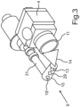
- Fig. 3 shows a schematic perspective view of an embodiment of the cleaning apparatus 9.
- the cleaning apparatus 9 comprises the telescopic arm 31, which in particular comprises the light source 13 and the cleaning device 10.
- the image sensor of the camera 4 is in particular formed as the detecting device 18. Thereto, the image sensor can in particular be set in a cleaning detection state.
- the telescopic arm 31 can in particular extend with the light source 13 and illuminate the front element 11 with the light beams 14.
- the light beams 14 are transmitted through the front element 11 corresponding to the degree of contamination on the front element 11 and received by the image sensor.
- the image sensor can in particular compare the received light beams by means of reference light beams and thereby perform a contamination analysis of the degree of contamination.
- background illumination of the environment 8 can be taken into account in the evaluation.
- a corresponding cleaning mode can be determined. For example, an amount of the liquid medium, an air mixture, an activation time or a cycle number can be set or determined depending on the evaluation.
- the front element 11 can again be checked for contamination and if a contamination should for example be again detected, thus, a cleaning cycle can again be performed.
- the further motor vehicles get provided the information of the evaluation device 19 such that the further motor vehicles can also use the information for cleaning.
- the information can be correspondingly stored in a storage medium of the cleaning apparatus 9 and the proper cleaning operation can also be stored depending on the degree of contamination.
- the stored information can for example be passed to a car wash since it is to be assumed that the motor vehicle 1 has a similar degree of contamination as the front element 11. Thereby, this information can be reliably passed to the car wash and the motor vehicle 1 can be reliably freed from the contamination.
- the cleaning apparatus 9 can also be employed for a windscreen or further optical sensors. It is also possible that a detector device 18' is co-arranged at the cleaning device 10 such that in case of a severe contamination of the front element 11, the contamination can be detected by the further detector device 18'.
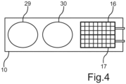
- Fig. 4 shows a schematic view of a cleaning device 10.
- the cleaning device 10 comprises the cleaning nozzle 29 and the air pressure nozzle 30.
- the cleaning device 10 comprises two light emitting diodes 16, 17, which are formed as a multi-array LED in the present example.
- a first light emitting diode 16 emits light beams 14 with a first wavelength
- a second light emitting diode 17 emits light beams 14 with a second wavelength different from the first wavelength.
- the degree of contamination is determined depending on the at least two different wavelengths. Thereby, the degree of contamination can be reliably determinable in particular with respect to the contamination material and/or the contamination intensity.
- the degree of contamination can be reliably determined, whereby a corresponding cleaning signal can be generated in improved manner, whereby the front element 11 can in turn be cleaned in improved manner.
- improved operation of an optical sensor such as for example the camera 4 can in particular be realized.
Landscapes
- Engineering & Computer Science (AREA)
- Mechanical Engineering (AREA)
- Water Supply & Treatment (AREA)
- Chemical & Material Sciences (AREA)
- Biochemistry (AREA)
- Physics & Mathematics (AREA)
- Health & Medical Sciences (AREA)
- Life Sciences & Earth Sciences (AREA)
- Pathology (AREA)
- Analytical Chemistry (AREA)
- Immunology (AREA)
- General Health & Medical Sciences (AREA)
- General Physics & Mathematics (AREA)
- Signal Processing (AREA)
- Multimedia (AREA)
- Investigating Or Analysing Materials By Optical Means (AREA)
- Studio Devices (AREA)
- Cleaning By Liquid Or Steam (AREA)
- General Engineering & Computer Science (AREA)
Description
- The invention relates to a cleaning apparatus for cleaning a transparent front element of an optical sensor for a motor vehicle. Further, the invention relates to an assembly.
- From the prior art, detector devices for receiving light beams for motor vehicles are already known. They comprise a transparent front element. In particular in the employment at the motor vehicle, contaminations on the transparent front element can therein occur. Impairment of the received information by the detector device can occur by the contamination. In order to be able to restore the functionality of the detector device, cleaning of the transparent front element is required. Presently, it is known that such a contamination is for example performed by manually activating a liquid and/or air cleaning system.
- Systems are known from the prior art, which can recognize a degree of contamination by means of a wavelength analysis. For example,
US 8,406,859 B2 discloses image spectroscopy, which results in collecting or capturing image-spectroscopic data. - Furthermore,
WO 2012/065952 A1 discloses a method for validating or verifying a cleaning process of a surface, which is contaminated with at least one chemical substrate.US 2016/311405 A1 discloses the preamble ofclaim 1. - It is the object of the present invention to provide a cleaning apparatus as well as an assembly, by means of which a contamination of a transparent front element can be reliably eliminated.
- This object is solved by a cleaning apparatus as well as an assembly according to the independent claims.
- An aspect of the invention relates to a cleaning apparatus for cleaning a transparent front element of an optical sensor of a camera for a motor vehicle. The cleaning apparatus comprises the transparent front element and a light source for externally illuminating the front element with light beams. Further, the cleaning apparatus comprises a detector device for receiving the light beams passed through the front element. Furthermore, the cleaning apparatus comprises an evaluation device, which is formed for evaluating the light beams received by the detector device for determining a degree of contamination of the front element. Depending on the evaluation, a control signal for a cleaning device of the cleaning apparatus can be generated such that the front element is cleanable by means of the cleaning device.
- Thereby, it is allowed that the degree of contamination can be accurately captured and then the control signal for cleaning the transparent front element can be correspondingly performed depending on the respective degree of contamination. Thus, it is allowed that light beams for the optical sensor can arrive at the optical sensor, for example at an image sensor of the optical sensor, in improved manner, whereby improved operation of the optical sensor is allowed. Thereby, impairment in particular does not occur at the optical sensor since the transparent front element is cleaned in improved manner.
- Furthermore, it is thereby allowed that the transparent front element can be purposefully cleaned. In other words, if a contamination should not be present on the transparent front element, the cleaning signal for the cleaning device is not generated. Thus, a cleaning medium can for example be saved. However, if the transparent front element should be contaminated, thus, the transparent front element can be correspondingly purposefully cleaned. Thereby, both the energy consumption of the cleaning device and for example the cleaning medium consumption of the cleaning apparatus can be reduced.
- In particular, after cleaning the transparent front element, further external illumination of the front element can be performed to check the cleaning of the front element and optionally, if a contamination should for example further be recognized, to be able to again perform a cleaning process.
- According to an advantageous form of configuration, at least the cleaning device can be mounted displaceably relative with respect to the front element, in particular mounted on a telescopic arm, and/or the light source and the cleaning device can be disposed in a common housing. By mounting the cleaning device on a telescopic arm, it is in particular allowed that improved aerodynamics of the motor vehicle can be realized since the cleaning device in particular does for example not protrude from a trim part of the motor vehicle if it should not be actuated. In particular upon actuation of the cleaning device, wherein actuation in particular means upon generation of the control signal, the telescopic arm with the cleaning device can then for example extend from the trim part and perform the cleaning of the front element. Thereby, it is in particular allowed that reliable cleaning of the front element can be performed with little negative aerodynamic effects since in particular after extending the telescopic arm with the cleaning device, improved cleaning of the front element can be performed due to the angular position to the front element. Alternatively or additionally, it is advantageous if the light source and the cleaning device are disposed in a common housing. In particular, the light source and the cleaning device can then be disposed within the one housing in material and space saving manner. Thus, the light source and the cleaning device can be formed as a common component. Thereby, reliable and efficient cleaning of the front element can be performed.
- Alternatively or additionally, it is possible that the detector device is disposed in the common housing with the light source and/or the cleaning device. Thereby, it is allowed that determination of the degree of contamination can yet be captured with a severe contamination of the front element even if light beams no longer get through the transparent front element.
- It has further proven advantageous if the cleaning apparatus is formed for generating ultrasonic waves, wherein the front element is cleanable by means of the ultrasonic waves. It is in particular possible that the ultrasonic waves are exerted on the contamination correspondingly long in time depending on the degree of contamination such that the contamination can be advantageously removed. Further, the ultrasonic waves can be emitted with different wavelengths such that a more advantageous cleaning of the front element can be performed.
- It is also advantageous if the cleaning device comprises a liquid cleaning medium, which is stored in a cleaning reservoir, and the liquid cleaning medium can be sprayed onto the front element via a cleaning nozzle of the cleaning device such that the front element is cleanable by means of the cleaning medium. The cleaning reservoir can for example be a cleaning reservoir of the cleaning apparatus, however, it is also possible that it is for example resorted to reservoirs already installed in the motor vehicle such that the cleaning medium of a windscreen wiping device is for example used and thus it can be resorted to the cleaning reservoir of the windscreen wiping device. Thereby, reliable cleaning of the front element can in particular be allowed. Furthermore, the cleaning can for example be performed without additional reservoir since it can be resorted to systems already installed in the motor vehicle.
- It has further proven advantageous if the cleaning apparatus comprises an air pressure nozzle, by means of which an air jet can be generated, which can be jetted to the front element, whereby the front element is cleanable. Thus, cleaning of the front element can be performed by means of air. Thereby, improved cleaning of the front element can be performed.
- According to a further advantageous form of configuration, the degree of contamination can be determinable depending on at least one received wavelength of the light beams and/or a contamination material and/or a contamination intensity can be determinable as the degree of contamination by means of the evaluation device, and the control signal can be generable at least depending on the contamination material and/or the contamination intensity. Since in particular different contamination materials and different contamination intensities, respectively, exert a different influence on the emitted wavelength by the light source and the received wavelength of the light beams, reliable determination of the degree of contamination in particular as a contamination material and/or as a contamination intensity can be determinable by means of this method. Thus, the degree of contamination can be determined in detailed manner and the control signal can be correspondingly generated. Thereby, advantageous cleaning of the front element can be performed.
- Preferably, it is possible that the light beams are received by means of the detector unit and compared by means of reference light beams. Thereby, the degree of contamination can be reliably determined.
- The invention further includes the light source comprising at least two light emitting diodes, wherein light beams with a first wavelength can be emitted by a first light emitting diode and light beams with a second wavelength different from the first wavelength can be emitted by at least one second light emitting diode. In particular, it can be provided that the wavelengths of the at least two light emitting diodes are in a range not visible to the human eye. For example, the wavelengths can be ultraviolet or infrared radiation. Furthermore, it is also possible that visible light beams are emitted. It is also possible that light beams with a higher wavelength than infrared can be emitted. It is also possible that a combination of different light beams can be emitted. Thereby, multi-spectral and hyper-spectral analysis is in particular allowed, which allows accurate characterization of the degree of contamination. Thereto, the detector unit and the transparent front element can in particular allow transmission and detection of the corresponding wavelengths. For example, this can be allowed by a standard silicon image sensor with filters with corresponding wavelengths or with corresponding combinations for receiving units, which are disposed in the image sensor. Further, it is possible that the light source comprises a plurality of light emitting diodes, which each emit light beams with different wavelength such that a reliable evaluation can be performed.
- According to a further advantageous form of configuration, at least information of an environment of the front element can be able to be taken into account in the evaluation of the received light beams. Thereby, improved calibration of the detector unit can be performed since the environmental light beams are known and can then for example be correspondingly subtracted from the reference light beams, to which they are compared, such that only the light beams emitted by the light source are taken into account in the evaluation of the degree of contamination.
- It is also advantageous if the cleaning apparatus is formed for receiving information, which relates to reception of light beams by an image sensor of the optical sensor, wherein the evaluation device is formed to take into account this information in the evaluation for the determination of the degree of contamination of the front element. In other words, a camera can for example serve as the optical sensor. Then, the captured information by the image sensor of the camera can be taken into account in the evaluation. In particular, only the image sensor of the optical sensor can be used for evaluation by the evaluation device of the cleaning apparatus. Thereby, the cleaning apparatus can still reliably determine the degree of contamination in particular reduced in components and thereby perform a reliable cleaning of the transparent front element.
- Further, it can be provided that the cleaning apparatus comprises a communication device for bidirectional communication of information with at least one information device disposed externally to the cleaning apparatus, wherein information received from the information device can be taken into account in the evaluation by the evaluation device. For example, information of a vehicle-to-infrastructure can be taken into account in the evaluation. It is also possible that information of a vehicle-to-vehicle structure can be taken into account in the evaluation. For example, the vehicle-to-infrastructure information and the vehicle-to-vehicle information, respectively, can be weighted, for example with respect to the input time, and then be incorporated in the evaluation. The vehicle-to-infrastructure information can for example be Cloud-based information.
- Preferably, it can be provided that other vehicles for example also obtain the information of the evaluation device and it is taken into account in a cleaning process in for example optical sensors of the further motor vehicles. This has the advantage that the further vehicles for example do not have to comprise a cleaning apparatus according to the invention, but only the corresponding cleaning device to be able to perform cleaning. The corresponding information about the cleaning process can be provided by the motor vehicle with the cleaning apparatus according to the invention.
- It has further proven advantageous if a plurality of control signals, in particular of different control signals, is generable by the evaluation device for the cleaning device. If the cleaning device should for example comprise an air pressure nozzle and a cleaning nozzle, a cleaning cycle can in particular be performed depending on the degree of contamination and in particular depending on the contamination intensity and the contamination material. For example, cleaning can then first be performed by means of the air pressure nozzle and subsequently by means of the cleaning nozzle. A possible combination of any proposed cleaning methods, in other words, by means of ultrasound, by means of the cleaning medium and by means of the air pressure nozzle, is also possible. It is also possible that the corresponding cleaning process can be performed multiple times.
- Preferably, it is possible that the information about for example a successful cleaning process is stored in a storage device of the motor vehicle such that it is available in the future. This stored information can for example also be provided for a car wash such that the motor vehicle provides this information to the car wash upon entry in the car wash such that it is for example informed about the degree of contamination and thereby about the contamination intensity and the contamination material such that a particularly preferred program can be automatically selected in the car wash. In that the motor vehicle has an at least similar contamination state as the transparent front element, thus, improved cleaning of the motor vehicle can be able to be performed.
- Preferably, the cleaning apparatus can for example also be formed in a screen wiping system for cleaning vehicle panes or windscreens.
- A further possibility is in that the cleaning apparatus is accommodated in a drone and the drone for example flies to a motor vehicle and determines the degree of contamination. For example, the drone can then fly from optical sensor to optical sensor and check the cleaning by means of the optical sensor.
- A further aspect relates to an assembly with a camera and with a cleaning apparatus according to any one of above mentioned aspects.
- In an advantageous form of configuration of the assembly, information of an image sensor of the camera can be receivable by the cleaning apparatus, wherein the received information of the image sensor can be taken into account in the evaluation by the evaluation device for determining the degree of contamination. In other words, the image sensor of the camera is additionally or alternatively used as the detector device. Thus, it is allowed that the image sensor of the camera performs the method, whereby components can in particular be saved. Thereby, simple capture of the light beams is possible such that evaluation of the captured light beams can be reliably performed.
- A still further aspect of the invention relates to a motor vehicle with a cleaning apparatus or with an assembly. In particular, the motor vehicle is formed as a passenger car.
- Advantageous forms of configuration of the cleaning apparatus are to be regarded as advantageous forms of configuration of the assembly and of the motor vehicle, respectively.
- Further features of the invention are apparent from the claims, the figures and the description of figures. The features and feature combinations mentioned above in the description as well as the features and feature combinations mentioned below in the description of figures and/or shown in the figures alone are usable not only in the respectively specified combination, but also in other combinations or alone without departing from the scope of the invention as defined by the claims.
- Now, the invention explained in more detail based on preferred embodiments as well as with reference to the attached drawings.
- There show:
- Fig. 1
- a schematic top view to an embodiment of a motor vehicle with an assembly;
- Fig. 2
- a schematic view of an embodiment of the assembly;
- Fig. 3
- a schematic perspective view of an embodiment of the assembly; and
- Fig. 4
- a schematic view of an embodiment of a cleaning device.
- In the figures, functionally identical elements are provided with the same reference characters.
-
Fig. 1 shows amotor vehicle 1 according to an embodiment of the present invention in a top view. In the present case, themotor vehicle 1 is formed as a passenger car. Themotor vehicle 1 comprises acamera system 2. Thecamera system 2 in turn comprises an image processing device 3, which can for example be constituted by an electronic controller of themotor vehicle 1. Moreover, thecamera system 2 comprises at least onecamera 4. In the present embodiment, thecamera system 2 for example comprises fourcameras 4, which are disposed distributed at themotor vehicle 1. However, only twocameras 4 or threecameras 4 or else more than fourcameras 4 can for example also be provided. Presently, one of thecameras 4 is disposed in arear area 5, one of thecameras 4 is disposed in afront area 7 of themotor vehicle 1 and the remaining twocameras 4 are disposed in a respectivelateral area 6, in particular in an area of the wing mirrors. Presently, the number and arrangement of thecameras 4 of thecamera system 2 are to be purely exemplarily understood. - An object OB in an
environment 8 of themotor vehicle 1 can be captured by thecameras 4. Preferably, the fourcameras 4 are formed identical in construction. In particular, a sequence of images can be provided by thecameras 4, which describe theenvironment 8. These images can be transmitted from thecameras 4 to the image processing device 3. Thus, thecamera system 2 serves for assisting the driver of themotor vehicle 1 in driving themotor vehicle 1. Thecamera system 2 can for example be a so-called electronic rearview mirror (then it preferably comprises twocameras 4 in the lateral areas 6) or an ACC system (Adaptive Cruise Control system) or a parking assistance system or other system. It can also be formed in the motor vehicle interior for capturing a person, in particular a vehicle driver. - The
motor vehicle 1 comprises acleaning apparatus 9. Alternatively, themotor vehicle 1 can comprise an assembly 32, which comprises at least onecamera 4 as an optical sensor and at least onecleaning apparatus 9. -
Fig. 2 shows a schematic view of an embodiment of thecleaning apparatus 9. In the following embodiment, thecleaning apparatus 9 comprises acleaning device 10 and a transparentfront element 11. Thecleaning device 10 and the transparentfront element 11 are disposed at atrim part 12 of themotor vehicle 1 in the present embodiment. Presently, the transparentfront element 11 is for example a lens of thecamera 4. - In the present embodiment, the
cleaning device 10 comprises alight source 13, which emits light beams 14 for externally illuminating thefront element 11. In particular, thelight source 13 and thecleaning device 10 are formed in acommon housing 15. - In particular, it can be provided that a lens of the
light source 13 andlight emitting diodes 16, 17 (Fig. 4 ) of thelight source 13 are formed as multi-array LEDS in order to be able to perform downsizing of thecleaning device 10. It can be provided that thelight emitting diodes - A
detector device 18 of thecleaning apparatus 9 is formed for receiving the light beams 14 passing through thefront element 11. It can be provided that thedetector device 18 is formed as an image sensor of thecamera 4. Thedetector device 18 in turn is coupled to anevaluation device 19, which in particular can perform a determination of the degree of contamination of thefront element 11. - In particular, it is allowed that the
detector device 18, which can for example be formed as an image sensor of thecamera 4, performs both the image processing for thecamera 4 and the detection for thecleaning apparatus 9. For example, light beams 14 in the ultraviolet range, in the range visible to the human eye, infrared range or in an even higher wavelength range can be detected by means of thedetector device 18. - Based on the passed light beams, in particular based on the wavelength of the light beams, the degree of contamination can in particular be determinable by means of the
evaluation device 19. In particular, a contamination material and/or a contamination intensity are determinable as the degree of contamination and acontrol signal 20 for acontrol device 21 can be generable depending on the degree of contamination such that acontrol signal 22 for thecleaning device 10 is reliably generable. - In the evaluation of the received
light beams 14, atleast information 23 of an environment of thefront element 11 can in particular be taken into account. Thisinformation 23 can in particular for example be environmental light beams such that they can be taken into account in the analysis. - Further, the
cleaning apparatus 9 can comprise acommunication device 24, which is formed forbidirectional communication information device 27 disposed externally to thecleaning apparatus 9, whereininformation 25 received from theinformation device 27 can be taken into account in the evaluation by theevaluation device 19. - The
information device 27 in turn can for example be formed as a part of a vehicle-to-infrastructure and vehicle-to-vehicle information device, respectively. Thus, data can for example be exchanged in Cloud-based manner such that thecleaning apparatus 9 can obtain receivedinformation 25 from this Cloud. Further, theinformation device 27 can be formed as a part of a further motor vehicle and theevaluation device 19 can for example send the processed information about the environment, in particular about the degree of contamination, to theinformation device 27 such that for example further motor vehicles, which in particular do not comprise acleaning apparatus 9 according to the invention, obtain the information such that a corresponding cleaning can also be performed on the further motor vehicle without corresponding detection. - The
cleaning apparatus 9, in particular thecleaning device 10, is in particular formed for generating ultrasonic waves, wherein thefront element 11 is cleanable by means of the ultrasonic waves. Further, thecleaning device 10 can comprise a liquid cleaning medium, which is stored in a cleaningreservoir 28, and the liquid cleaning medium can be sprayed onto thefront element 11 via a cleaningnozzle 29 of thecleaning device 10 such that thefront element 11 is cleanable. The cleaningreservoir 28 can for example be a cleaning reservoir of thecleaning apparatus 9 or a cleaning reservoir of a wiping system of themotor vehicle 1. - Further, it can be provided that the
cleaning apparatus 9 comprises anair pressure nozzle 30, by means of which an air jet is generable, which can be jetted to thefront element 11, whereby thefront element 11 is cleanable. - Further, it can be provided that at least the
cleaning device 10, in the present case thecleaning device 10 and thelight source 13, is mounted displaceably relative at least with respect to thefront element 11 on atelescopic arm 31. - Further, it can be provided that a plurality of control signals 22, in particular of different control signals 22, is generable for the
cleaning device 10 by means of thecontrol device 21 such that thefront element 11 is cleanable by means of the different possibilities, for example by means of an air jet and/or by means of the cleaning medium and/or by means of ultrasonic waves. In particular, a cleaning cycle can also be performed such that the cycle can be successively performed for example by means of the different cleaning possibilities such that advantageous cleaning of thefront element 11 can be performed. -
Fig. 3 shows a schematic perspective view of an embodiment of thecleaning apparatus 9. Thecleaning apparatus 9 comprises thetelescopic arm 31, which in particular comprises thelight source 13 and thecleaning device 10. In the present embodiment, the image sensor of thecamera 4 is in particular formed as the detectingdevice 18. Thereto, the image sensor can in particular be set in a cleaning detection state. Thetelescopic arm 31 can in particular extend with thelight source 13 and illuminate thefront element 11 with the light beams 14. The light beams 14 are transmitted through thefront element 11 corresponding to the degree of contamination on thefront element 11 and received by the image sensor. The image sensor can in particular compare the received light beams by means of reference light beams and thereby perform a contamination analysis of the degree of contamination. In particular, background illumination of theenvironment 8 can be taken into account in the evaluation. Depending on the evaluation, a corresponding cleaning mode can be determined. For example, an amount of the liquid medium, an air mixture, an activation time or a cycle number can be set or determined depending on the evaluation. - After cleaning, the
front element 11 can again be checked for contamination and if a contamination should for example be again detected, thus, a cleaning cycle can again be performed. - It is possible that the further motor vehicles get provided the information of the
evaluation device 19 such that the further motor vehicles can also use the information for cleaning. It is also possible that the information can be correspondingly stored in a storage medium of thecleaning apparatus 9 and the proper cleaning operation can also be stored depending on the degree of contamination. It is also possible that the stored information can for example be passed to a car wash since it is to be assumed that themotor vehicle 1 has a similar degree of contamination as thefront element 11. Thereby, this information can be reliably passed to the car wash and themotor vehicle 1 can be reliably freed from the contamination. - For example, the
cleaning apparatus 9 can also be employed for a windscreen or further optical sensors. It is also possible that a detector device 18' is co-arranged at thecleaning device 10 such that in case of a severe contamination of thefront element 11, the contamination can be detected by the further detector device 18'. -
Fig. 4 shows a schematic view of acleaning device 10. In the following embodiment, thecleaning device 10 comprises the cleaningnozzle 29 and theair pressure nozzle 30. Further, thecleaning device 10 comprises two light emittingdiodes light emitting diode 16 emits light beams 14 with a first wavelength and a secondlight emitting diode 17 emits light beams 14 with a second wavelength different from the first wavelength. In particular, it is thereby allowed that the degree of contamination is determined depending on the at least two different wavelengths. Thereby, the degree of contamination can be reliably determinable in particular with respect to the contamination material and/or the contamination intensity. In particular since different contamination materials have different influences with respect to the transmitted light beams in a spectral analysis, thus, the degree of contamination can be reliably determined, whereby a corresponding cleaning signal can be generated in improved manner, whereby thefront element 11 can in turn be cleaned in improved manner. Thereby, improved operation of an optical sensor such as for example thecamera 4 can in particular be realized.
Claims (12)
- Cleaning apparatus (9) for cleaning a transparent front element (11) of an optical sensor of a camera (4) for a motor vehicle (1), including the transparent front element (11) and including a light source (13) for externally illuminating the front element (11) with light beams (14), including a detector device (18) for receiving the light beams passed through the front element (11), and including an evaluation device (19), which is formed for evaluating the light beams received by the detector device (18) for determining a degree of contamination of the front element (11), wherein a control signal (22) for a cleaning device (10) of the cleaning apparatus (9) is generated depending on the evaluation such that the front element (11) is cleanable by means of the cleaning device (10),
characterised in that
the light source (13) comprises at least two light emitting diodes (16, 17), wherein light beams (14) with a first wavelength can be emitted by a first light emitting diode (16) and light beams (14) with a second wavelength different from the first wavelength can be emitted by at least one second light emitting diode (17). - Cleaning apparatus (9) according to claim 1,
characterized in that
at least the cleaning device (10) is mounted displaceable relative with respect to the front element (11), in particular is mounted on a telescopic arm (31), and/or the light source (13) and the cleaning apparatus (9) are disposed in a common housing (15). - Cleaning apparatus (9) according to any one of the preceding claims,
characterized in that
the cleaning apparatus (9) is formed for generating ultrasonic waves, wherein the front element (11) is cleanable by means of the ultrasonic waves. - Cleaning apparatus (9) according to any one of the preceding claims,
characterized in that
the cleaning apparatus (9) comprises a liquid cleaning medium, which is stored in a cleaning reservoir (28), and the liquid cleaning medium can be sprayed onto the front element (11) via a cleaning nozzle (29) of the cleaning device (10) such that the front element (11) is cleanable by means of the cleaning medium. - Cleaning apparatus (9) according to any one of the preceding claims,
characterized in that
the cleaning apparatus (9) comprises an air pressure nozzle (30), by means of which an air jet is generable, which can be jetted to the front element (11), whereby the front element (11) is cleanable. - Cleaning apparatus (9) according to any one of the preceding claims,
characterized in that
depending on at least one received wavelength of the light beams (14), the degree of contamination is determinable and/or a contamination material and/or a contamination intensity are determinable as the degree of contamination by means of the evaluation device (19), and the control signal (22) is generable at least depending on the contamination material and/or the contamination intensity. - Cleaning apparatus (9) according to any one of the preceding claims,
characterized in that
at least information (23) of an environment of the front element (11) can be taken into account in the evaluation of the received light beams. - Cleaning apparatus (9) according to any one of the preceding claims,
characterized in that
the cleaning apparatus (9) is formed for receiving information relating to reception of light beams by an image sensor of the optical sensor (4), wherein the evaluation device (19) is formed to take into account this information in the evaluation for determining the degree of contamination of the front element (11). - Cleaning apparatus (9) according to any one of the preceding claims,
characterized in that
the cleaning apparatus (9) comprises a communication device (24) for bidirectional communication (25, 26) of information with at least one information device (27) disposed externally to the cleaning apparatus (9), wherein information (25) received from the information device (27) can be taken into account in the evaluation by the evaluation device (19). - Cleaning apparatus (9) according to any one of the preceding claims,
characterized in that
a plurality of control signals (22), in particular of different control signals (22), for the cleaning device (10) is generable by the evaluation device (19). - Assembly (32) with a camera (4) and with a cleaning apparatus (9) according to any one of claims 1 to 10.
- Assembly (32) according to claim 11,
characterized in that
at least information of an image sensor of the camera (4) is receivable by the cleaning apparatus (9), wherein the received information of the image sensor can be taken into account in the evaluation by the evaluation device (19) for determining the degree of contamination.
Applications Claiming Priority (2)
| Application Number | Priority Date | Filing Date | Title |
|---|---|---|---|
| DE102018100805.8A DE102018100805A1 (en) | 2018-01-16 | 2018-01-16 | Cleaning device for cleaning a translucent front element of an optical sensor for a motor vehicle, arrangement and method |
| PCT/EP2019/050898 WO2019141665A1 (en) | 2018-01-16 | 2019-01-15 | Cleaning apparatus for cleaning a transparent front element of an optical sensor for a motor vehicle, assembly as well as method |
Publications (2)
| Publication Number | Publication Date |
|---|---|
| EP3740404A1 EP3740404A1 (en) | 2020-11-25 |
| EP3740404B1 true EP3740404B1 (en) | 2024-02-28 |
Family
ID=65036787
Family Applications (1)
| Application Number | Title | Priority Date | Filing Date |
|---|---|---|---|
| EP19700897.2A Active EP3740404B1 (en) | 2018-01-16 | 2019-01-15 | Cleaning apparatus for cleaning a transparent front element of an optical sensor for a motor vehicle, as well as assembly |
Country Status (7)
| Country | Link |
|---|---|
| US (1) | US20200377058A1 (en) |
| EP (1) | EP3740404B1 (en) |
| JP (1) | JP7166346B2 (en) |
| KR (1) | KR102432317B1 (en) |
| CN (1) | CN111727140B (en) |
| DE (1) | DE102018100805A1 (en) |
| WO (1) | WO2019141665A1 (en) |
Families Citing this family (8)
| Publication number | Priority date | Publication date | Assignee | Title |
|---|---|---|---|---|
| US11581481B2 (en) | 2020-02-12 | 2023-02-14 | Continental Autonomous Mobility US, LLC | Optical surface cleaning with directed energy waves |
| US11719928B2 (en) * | 2020-09-28 | 2023-08-08 | Waymo Llc | Cleaning for rotating sensors |
| US11702044B2 (en) | 2020-12-07 | 2023-07-18 | Ford Global Technologies, Llc | Vehicle sensor cleaning and cooling |
| DE102023104709A1 (en) * | 2023-02-27 | 2024-08-29 | Bayerische Motoren Werke Aktiengesellschaft | Sensor system for a vehicle and cleaning method for a sensor system of a vehicle |
| KR102817114B1 (en) * | 2023-11-13 | 2025-06-05 | 주식회사 니프코코리아 | Cleaning nozzle for automobile lidar sensor cleaning device |
| CN117485292A (en) * | 2023-11-20 | 2024-02-02 | 中国第一汽车股份有限公司 | A hidden electronic exterior mirror automatic cleaning device and its control method |
| WO2026078876A1 (en) * | 2024-10-11 | 2026-04-16 | 日産自動車株式会社 | Vehicle appearance inspection device and vehicle appearance inspection method |
| KR102930939B1 (en) * | 2025-09-29 | 2026-02-26 | 주식회사 라이드플럭스 | Sensor cleaning device for autonomous vehicle |
Citations (2)
| Publication number | Priority date | Publication date | Assignee | Title |
|---|---|---|---|---|
| DE19704818A1 (en) * | 1996-02-13 | 1997-08-14 | Marquardt Gmbh | Optical sensor system for determining measurement value esp for motor vehicle control |
| EP1399340A1 (en) * | 2001-06-28 | 2004-03-24 | Valeo Electrical Systems, Inc. | Interleaved mosaic imaging rain sensor |
Family Cites Families (47)
| Publication number | Priority date | Publication date | Assignee | Title |
|---|---|---|---|---|
| DE29516779U1 (en) * | 1995-10-24 | 1996-01-11 | Docter Optic Wetzlar GmbH, 35641 Schöffengrund | Device for determining the translucency of translucent panes |
| DE19951831A1 (en) * | 1999-10-28 | 2001-05-03 | Valeo Auto Electric Gmbh | Sensor for the detection of drops of moisture and / or dirt particles on a pane and method for operating such a sensor |
| FR2810605B1 (en) * | 2000-06-22 | 2002-09-20 | Valeo Systemes Dessuyage | AUTOMATIC CONTROL EQUIPMENT FOR CLEANING A PLATE SURFACE HAVING VARIOUS DIRT CONDITIONS, AND IMPLEMENTATION METHOD |
| DE10048033A1 (en) * | 2000-09-26 | 2002-05-23 | Siemens Ag | Window cleaning system and method for cleaning a window |
| DE10049851C1 (en) * | 2000-10-09 | 2002-06-06 | Bosch Gmbh Robert | Transparency measuring device e.g. for optical element positioned in front of sensor, uses separate radiation-sensitive element and/or element of sensor for monitoring transmitted radiation level |
| DE102004038422B3 (en) * | 2004-07-30 | 2006-01-12 | Schefenacker Vision Systems Germany Gmbh | Sensor device, use of a sensor device and vehicle light |
| US20100155584A1 (en) * | 2006-09-13 | 2010-06-24 | Bernd Mack | Sensor for detecting dirt and/or rain and method for operating a sensor |
| DE102007007850B4 (en) * | 2007-02-16 | 2019-08-14 | Continental Automotive Gmbh | Nozzle device for cleaning a disk |
| DE102007013688B3 (en) * | 2007-03-22 | 2008-11-06 | Odelo Gmbh | Optoelectronic sensor device and method for determining the transparency of a surface exposed to contamination |
| JP2008275390A (en) * | 2007-04-26 | 2008-11-13 | Denso Corp | Raindrop detector |
| JP2010014494A (en) * | 2008-07-02 | 2010-01-21 | Denso Corp | Foreign matter detector, foreign matter detecting program, foreign matter removing device, and on-vehicle communications apparatus |
| US8406859B2 (en) | 2008-08-10 | 2013-03-26 | Board Of Regents, The University Of Texas System | Digital light processing hyperspectral imaging apparatus |
| JP5056919B2 (en) * | 2009-09-29 | 2012-10-24 | 株式会社デンソー | In-vehicle optical sensor cover and in-vehicle optical sensor device |
| EP2557414B1 (en) * | 2009-12-21 | 2015-03-25 | C.R.F. Società Consortile per Azioni | Optical detection system for motor-vehicles having multiple functions, including detection of the condition of the road surface |
| US20110292212A1 (en) * | 2010-05-27 | 2011-12-01 | Asmo Co., Ltd. | Washer nozzle for vehicle mounted camera, vehicle mounted camera, and washer device for vehicle |
| IES20100730A2 (en) | 2010-11-18 | 2012-02-15 | Ian Jones | A method of validating a cleaning process |
| DE102011003803A1 (en) * | 2011-02-08 | 2012-08-09 | Robert Bosch Gmbh | Method and device for determining a clarity of a pane of a vehicle |
| MY183226A (en) * | 2012-07-03 | 2021-02-18 | Nissan Motor | On-board device controlling accumulation removing units |
| JP6055224B2 (en) * | 2012-07-27 | 2016-12-27 | クラリオン株式会社 | Lens cleaning device |
| US9380190B2 (en) * | 2012-08-06 | 2016-06-28 | Gentex Corporation | Rotating lens apparatus |
| DE102012222126B4 (en) * | 2012-12-04 | 2020-06-04 | Robert Bosch Gmbh | Method and device for controlling a cleaning device for a vehicle camera, method for cleaning a vehicle camera and camera system for a vehicle |
| JP6417757B2 (en) * | 2013-09-19 | 2018-11-07 | 株式会社デンソー | In-vehicle optical sensor cleaning device |
| DE102014200219B4 (en) * | 2014-01-09 | 2025-02-13 | Continental Autonomous Mobility Germany GmbH | Device for cleaning an optical element of a camera system |
| DE102014004172A1 (en) * | 2014-03-22 | 2014-09-18 | Daimler Ag | Fender for a camera of a motor car |
| DE102014015914A1 (en) * | 2014-04-09 | 2015-10-15 | Huf Hülsbeck & Fürst Gmbh & Co. Kg | Motor vehicle door handle unit with camera |
| US10882495B2 (en) * | 2014-05-27 | 2021-01-05 | Fico Transpar, S.A. | System and method for cleaning a vehicle-mounted sensor |
| DE102014015993B4 (en) * | 2014-10-28 | 2021-01-07 | Audi Ag | Motor vehicle with at least one cleaning device for at least one component of the motor vehicle and a method for operating a cleaning device for at least one component of a motor vehicle |
| JP6332692B2 (en) * | 2014-10-31 | 2018-05-30 | 株式会社デンソー | In-vehicle optical sensor foreign material removal device |
| US20160170203A1 (en) * | 2014-12-12 | 2016-06-16 | GM Global Technology Operations LLC | Ultrasonic lens cleaning conveyor |
| DE102014226358B4 (en) * | 2014-12-18 | 2019-04-11 | Bayerische Motoren Werke Aktiengesellschaft | Apparatus and method for detecting surface pollution of a vehicle |
| DE102015002465A1 (en) * | 2015-02-27 | 2016-09-01 | Hella Kgaa Hueck & Co. | Method for fine dust measurement and fine dust sensor for the determination of the particle size of fine dust |
| US10035498B2 (en) * | 2015-04-22 | 2018-07-31 | Ford Global Technologies, Llc | Vehicle camera cleaning system |
| JP6700584B2 (en) * | 2016-01-19 | 2020-05-27 | 株式会社デンソー | In-vehicle optical sensor cleaning device |
| US9914436B2 (en) * | 2015-05-28 | 2018-03-13 | Bader Abdullah ALMALKI | Automated vehicle snow and ice removal |
| JP2016222181A (en) * | 2015-06-02 | 2016-12-28 | カルソニックカンセイ株式会社 | Vehicular imaging device |
| DE102015210469A1 (en) * | 2015-06-08 | 2016-12-08 | Bombardier Transportation Gmbh | Arrangement for optically detecting an environment of a vehicle, in particular a rail vehicle or a bus, vehicle with the arrangement and method for operating the arrangement |
| FR3039113B1 (en) * | 2015-07-22 | 2017-07-28 | Valeo Systemes Dessuyage | DEVICE FOR CLEANING A SENSOR FOR A MOTOR VEHICLE |
| FR3047456B1 (en) * | 2016-02-05 | 2018-03-02 | Valeo Systemes Dessuyage | OPTICAL DETECTION SYSTEM FOR A MOTOR VEHICLE AND DEVICE FOR CLEANING SUCH A SYSTEM |
| US10358117B2 (en) * | 2016-02-10 | 2019-07-23 | Honda Motor Co., Ltd. | Apparatus for controlling or otherwise manipulating vehicle components, and methods of use and manufacture thereof |
| DE102016002578A1 (en) * | 2016-03-03 | 2017-09-07 | GM Global Technology Operations LLC (n. d. Ges. d. Staates Delaware) | Exterior mirror with structure-borne sound wave generating element and method for controlling such a structure-borne sound wave generating element |
| US10399106B2 (en) * | 2017-01-19 | 2019-09-03 | Ford Global Technologies, Llc | Camera and washer spray diagnostic |
| US10527843B2 (en) * | 2017-05-12 | 2020-01-07 | International Business Machines Corporation | Ultra-sonic self-cleaning system |
| US10807569B2 (en) * | 2017-05-16 | 2020-10-20 | Ford Global Technologies, Llc | Vehicle washer fluid delivery diagnostics and cleaning |
| US10489934B2 (en) * | 2017-05-26 | 2019-11-26 | Ford Global Technologies, Llc | Vehicle exterior conditioning |
| US10196047B1 (en) * | 2017-08-07 | 2019-02-05 | Ford Global Technologies, Llc | Contamination prevention of vehicle cameras and sensors |
| DE102017217939B4 (en) * | 2017-10-09 | 2021-09-30 | Audi Ag | Method and arrangement for determining an optical variable on a sensor cover; Motor vehicle |
| US20190106085A1 (en) * | 2017-10-10 | 2019-04-11 | GM Global Technology Operations LLC | System and method for automated decontamination of vehicle optical sensor lens covers |
-
2018
- 2018-01-16 DE DE102018100805.8A patent/DE102018100805A1/en not_active Withdrawn
-
2019
- 2019-01-15 US US16/961,423 patent/US20200377058A1/en not_active Abandoned
- 2019-01-15 WO PCT/EP2019/050898 patent/WO2019141665A1/en not_active Ceased
- 2019-01-15 CN CN201980013768.3A patent/CN111727140B/en active Active
- 2019-01-15 JP JP2020539037A patent/JP7166346B2/en active Active
- 2019-01-15 KR KR1020207023295A patent/KR102432317B1/en active Active
- 2019-01-15 EP EP19700897.2A patent/EP3740404B1/en active Active
Patent Citations (2)
| Publication number | Priority date | Publication date | Assignee | Title |
|---|---|---|---|---|
| DE19704818A1 (en) * | 1996-02-13 | 1997-08-14 | Marquardt Gmbh | Optical sensor system for determining measurement value esp for motor vehicle control |
| EP1399340A1 (en) * | 2001-06-28 | 2004-03-24 | Valeo Electrical Systems, Inc. | Interleaved mosaic imaging rain sensor |
Also Published As
| Publication number | Publication date |
|---|---|
| CN111727140B (en) | 2023-11-10 |
| KR102432317B1 (en) | 2022-08-12 |
| WO2019141665A1 (en) | 2019-07-25 |
| DE102018100805A1 (en) | 2019-07-18 |
| KR20200106078A (en) | 2020-09-10 |
| JP7166346B2 (en) | 2022-11-07 |
| CN111727140A (en) | 2020-09-29 |
| US20200377058A1 (en) | 2020-12-03 |
| EP3740404A1 (en) | 2020-11-25 |
| JP2021511244A (en) | 2021-05-06 |
Similar Documents
| Publication | Publication Date | Title |
|---|---|---|
| EP3740404B1 (en) | Cleaning apparatus for cleaning a transparent front element of an optical sensor for a motor vehicle, as well as assembly | |
| CN103608722B (en) | Camera system for vehicle | |
| JP3163889U (en) | An optical sensor device mounted on a vehicle for driving assistance and / or for automatically operating a system provided in the vehicle | |
| KR101707248B1 (en) | Camera system and method for capturing the surroundings of a vehicle | |
| US6603137B2 (en) | Differential imaging rain sensor | |
| US8913133B2 (en) | Camera system for a motor vehicle, and motor vehicle equipped with a camera system | |
| US9777518B2 (en) | Collision protection device for a pivotable hatch of a motor vehicle, hatch, motor vehicle and corresponding method | |
| US9128813B2 (en) | Method and device for assisting a driver while driving a vehicle by detecting weather-related visibility limitations | |
| CN104039610B (en) | Camera system, especially for a vehicle | |
| US6614043B2 (en) | Imaging rain sensor illumination positioning system | |
| EP3002711B1 (en) | Image capturing apparatus, image capturing method, carrier medium, and device control system for controlling vehicle-mounted devices | |
| US20080088702A1 (en) | Camera system, method for operation of a camera system and sensor device of a camera system | |
| US20140029005A1 (en) | Method and device for determining an optical clarity through a car window | |
| US9676329B2 (en) | Camera system and method for operating a camera system for a motor vehicle | |
| US20200103361A1 (en) | Display Device With Fitting Detection Device And Method For Operating A Fitting Detection, An Exterior Mirror And A Motor Vehicle | |
| EP2999207A1 (en) | Vehicle optical sensor system | |
| WO2011153990A1 (en) | Optical device having a bifocal optical element and a mirror element | |
| US12501128B2 (en) | Camera device for a vehicle and vehicle | |
| US20160339873A1 (en) | Illumination for Detecting Raindrops on a Pane by Means of a Camera | |
| CN112861600A (en) | Method and device for determining an optical influence on a camera | |
| JPH04507227A (en) | Method and device for controlling windscreen wipers | |
| CN111316336A (en) | Method for operating a motor vehicle with at least one exterior camera and motor vehicle with at least one exterior camera | |
| JP2014081477A (en) | Imaging apparatus | |
| CN117355445A (en) | Rain sensor system, vehicle and method for detecting rain | |
| JPH11134480A (en) | In-vehicle camera displacement detection device |
Legal Events
| Date | Code | Title | Description |
|---|---|---|---|
| STAA | Information on the status of an ep patent application or granted ep patent |
Free format text: STATUS: UNKNOWN |
|
| STAA | Information on the status of an ep patent application or granted ep patent |
Free format text: STATUS: THE INTERNATIONAL PUBLICATION HAS BEEN MADE |
|
| PUAI | Public reference made under article 153(3) epc to a published international application that has entered the european phase |
Free format text: ORIGINAL CODE: 0009012 |
|
| STAA | Information on the status of an ep patent application or granted ep patent |
Free format text: STATUS: REQUEST FOR EXAMINATION WAS MADE |
|
| 17P | Request for examination filed |
Effective date: 20200709 |
|
| AK | Designated contracting states |
Kind code of ref document: A1 Designated state(s): AL AT BE BG CH CY CZ DE DK EE ES FI FR GB GR HR HU IE IS IT LI LT LU LV MC MK MT NL NO PL PT RO RS SE SI SK SM TR |
|
| AX | Request for extension of the european patent |
Extension state: BA ME |
|
| DAV | Request for validation of the european patent (deleted) | ||
| DAX | Request for extension of the european patent (deleted) | ||
| STAA | Information on the status of an ep patent application or granted ep patent |
Free format text: STATUS: EXAMINATION IS IN PROGRESS |
|
| 17Q | First examination report despatched |
Effective date: 20210729 |
|
| P01 | Opt-out of the competence of the unified patent court (upc) registered |
Effective date: 20230528 |
|
| GRAP | Despatch of communication of intention to grant a patent |
Free format text: ORIGINAL CODE: EPIDOSNIGR1 |
|
| STAA | Information on the status of an ep patent application or granted ep patent |
Free format text: STATUS: GRANT OF PATENT IS INTENDED |
|
| INTG | Intention to grant announced |
Effective date: 20230927 |
|
| GRAS | Grant fee paid |
Free format text: ORIGINAL CODE: EPIDOSNIGR3 |
|
| GRAA | (expected) grant |
Free format text: ORIGINAL CODE: 0009210 |
|
| STAA | Information on the status of an ep patent application or granted ep patent |
Free format text: STATUS: THE PATENT HAS BEEN GRANTED |
|
| AK | Designated contracting states |
Kind code of ref document: B1 Designated state(s): AL AT BE BG CH CY CZ DE DK EE ES FI FR GB GR HR HU IE IS IT LI LT LU LV MC MK MT NL NO PL PT RO RS SE SI SK SM TR |
|
| REG | Reference to a national code |
Ref country code: GB Ref legal event code: FG4D |
|
| REG | Reference to a national code |
Ref country code: CH Ref legal event code: EP |
|
| REG | Reference to a national code |
Ref country code: DE Ref legal event code: R096 Ref document number: 602019047267 Country of ref document: DE |
|
| REG | Reference to a national code |
Ref country code: IE Ref legal event code: FG4D |
|
| REG | Reference to a national code |
Ref country code: LT Ref legal event code: MG9D |
|
| PG25 | Lapsed in a contracting state [announced via postgrant information from national office to epo] |
Ref country code: IS Free format text: LAPSE BECAUSE OF FAILURE TO SUBMIT A TRANSLATION OF THE DESCRIPTION OR TO PAY THE FEE WITHIN THE PRESCRIBED TIME-LIMIT Effective date: 20240628 |
|
| REG | Reference to a national code |
Ref country code: NL Ref legal event code: MP Effective date: 20240228 |
|
| PG25 | Lapsed in a contracting state [announced via postgrant information from national office to epo] |
Ref country code: LT Free format text: LAPSE BECAUSE OF FAILURE TO SUBMIT A TRANSLATION OF THE DESCRIPTION OR TO PAY THE FEE WITHIN THE PRESCRIBED TIME-LIMIT Effective date: 20240228 |
|
| PG25 | Lapsed in a contracting state [announced via postgrant information from national office to epo] |
Ref country code: GR Free format text: LAPSE BECAUSE OF FAILURE TO SUBMIT A TRANSLATION OF THE DESCRIPTION OR TO PAY THE FEE WITHIN THE PRESCRIBED TIME-LIMIT Effective date: 20240529 |
|
| PG25 | Lapsed in a contracting state [announced via postgrant information from national office to epo] |
Ref country code: RS Free format text: LAPSE BECAUSE OF FAILURE TO SUBMIT A TRANSLATION OF THE DESCRIPTION OR TO PAY THE FEE WITHIN THE PRESCRIBED TIME-LIMIT Effective date: 20240528 Ref country code: NL Free format text: LAPSE BECAUSE OF FAILURE TO SUBMIT A TRANSLATION OF THE DESCRIPTION OR TO PAY THE FEE WITHIN THE PRESCRIBED TIME-LIMIT Effective date: 20240228 Ref country code: HR Free format text: LAPSE BECAUSE OF FAILURE TO SUBMIT A TRANSLATION OF THE DESCRIPTION OR TO PAY THE FEE WITHIN THE PRESCRIBED TIME-LIMIT Effective date: 20240228 |
|
| PG25 | Lapsed in a contracting state [announced via postgrant information from national office to epo] |
Ref country code: ES Free format text: LAPSE BECAUSE OF FAILURE TO SUBMIT A TRANSLATION OF THE DESCRIPTION OR TO PAY THE FEE WITHIN THE PRESCRIBED TIME-LIMIT Effective date: 20240228 |
|
| PG25 | Lapsed in a contracting state [announced via postgrant information from national office to epo] |
Ref country code: RS Free format text: LAPSE BECAUSE OF FAILURE TO SUBMIT A TRANSLATION OF THE DESCRIPTION OR TO PAY THE FEE WITHIN THE PRESCRIBED TIME-LIMIT Effective date: 20240528 Ref country code: NO Free format text: LAPSE BECAUSE OF FAILURE TO SUBMIT A TRANSLATION OF THE DESCRIPTION OR TO PAY THE FEE WITHIN THE PRESCRIBED TIME-LIMIT Effective date: 20240528 Ref country code: NL Free format text: LAPSE BECAUSE OF FAILURE TO SUBMIT A TRANSLATION OF THE DESCRIPTION OR TO PAY THE FEE WITHIN THE PRESCRIBED TIME-LIMIT Effective date: 20240228 Ref country code: LT Free format text: LAPSE BECAUSE OF FAILURE TO SUBMIT A TRANSLATION OF THE DESCRIPTION OR TO PAY THE FEE WITHIN THE PRESCRIBED TIME-LIMIT Effective date: 20240228 Ref country code: IS Free format text: LAPSE BECAUSE OF FAILURE TO SUBMIT A TRANSLATION OF THE DESCRIPTION OR TO PAY THE FEE WITHIN THE PRESCRIBED TIME-LIMIT Effective date: 20240628 Ref country code: HR Free format text: LAPSE BECAUSE OF FAILURE TO SUBMIT A TRANSLATION OF THE DESCRIPTION OR TO PAY THE FEE WITHIN THE PRESCRIBED TIME-LIMIT Effective date: 20240228 Ref country code: GR Free format text: LAPSE BECAUSE OF FAILURE TO SUBMIT A TRANSLATION OF THE DESCRIPTION OR TO PAY THE FEE WITHIN THE PRESCRIBED TIME-LIMIT Effective date: 20240529 Ref country code: FI Free format text: LAPSE BECAUSE OF FAILURE TO SUBMIT A TRANSLATION OF THE DESCRIPTION OR TO PAY THE FEE WITHIN THE PRESCRIBED TIME-LIMIT Effective date: 20240228 Ref country code: ES Free format text: LAPSE BECAUSE OF FAILURE TO SUBMIT A TRANSLATION OF THE DESCRIPTION OR TO PAY THE FEE WITHIN THE PRESCRIBED TIME-LIMIT Effective date: 20240228 Ref country code: BG Free format text: LAPSE BECAUSE OF FAILURE TO SUBMIT A TRANSLATION OF THE DESCRIPTION OR TO PAY THE FEE WITHIN THE PRESCRIBED TIME-LIMIT Effective date: 20240228 |
|
| PG25 | Lapsed in a contracting state [announced via postgrant information from national office to epo] |
Ref country code: PL Free format text: LAPSE BECAUSE OF FAILURE TO SUBMIT A TRANSLATION OF THE DESCRIPTION OR TO PAY THE FEE WITHIN THE PRESCRIBED TIME-LIMIT Effective date: 20240228 Ref country code: PT Free format text: LAPSE BECAUSE OF FAILURE TO SUBMIT A TRANSLATION OF THE DESCRIPTION OR TO PAY THE FEE WITHIN THE PRESCRIBED TIME-LIMIT Effective date: 20240628 |
|
| REG | Reference to a national code |
Ref country code: AT Ref legal event code: MK05 Ref document number: 1660959 Country of ref document: AT Kind code of ref document: T Effective date: 20240228 |
|
| PG25 | Lapsed in a contracting state [announced via postgrant information from national office to epo] |
Ref country code: SE Free format text: LAPSE BECAUSE OF FAILURE TO SUBMIT A TRANSLATION OF THE DESCRIPTION OR TO PAY THE FEE WITHIN THE PRESCRIBED TIME-LIMIT Effective date: 20240228 Ref country code: PT Free format text: LAPSE BECAUSE OF FAILURE TO SUBMIT A TRANSLATION OF THE DESCRIPTION OR TO PAY THE FEE WITHIN THE PRESCRIBED TIME-LIMIT Effective date: 20240628 Ref country code: PL Free format text: LAPSE BECAUSE OF FAILURE TO SUBMIT A TRANSLATION OF THE DESCRIPTION OR TO PAY THE FEE WITHIN THE PRESCRIBED TIME-LIMIT Effective date: 20240228 Ref country code: LV Free format text: LAPSE BECAUSE OF FAILURE TO SUBMIT A TRANSLATION OF THE DESCRIPTION OR TO PAY THE FEE WITHIN THE PRESCRIBED TIME-LIMIT Effective date: 20240228 |
|
| PG25 | Lapsed in a contracting state [announced via postgrant information from national office to epo] |
Ref country code: DK Free format text: LAPSE BECAUSE OF FAILURE TO SUBMIT A TRANSLATION OF THE DESCRIPTION OR TO PAY THE FEE WITHIN THE PRESCRIBED TIME-LIMIT Effective date: 20240228 |
|
| PG25 | Lapsed in a contracting state [announced via postgrant information from national office to epo] |
Ref country code: SM Free format text: LAPSE BECAUSE OF FAILURE TO SUBMIT A TRANSLATION OF THE DESCRIPTION OR TO PAY THE FEE WITHIN THE PRESCRIBED TIME-LIMIT Effective date: 20240228 |
|
| PG25 | Lapsed in a contracting state [announced via postgrant information from national office to epo] |
Ref country code: EE Free format text: LAPSE BECAUSE OF FAILURE TO SUBMIT A TRANSLATION OF THE DESCRIPTION OR TO PAY THE FEE WITHIN THE PRESCRIBED TIME-LIMIT Effective date: 20240228 Ref country code: CZ Free format text: LAPSE BECAUSE OF FAILURE TO SUBMIT A TRANSLATION OF THE DESCRIPTION OR TO PAY THE FEE WITHIN THE PRESCRIBED TIME-LIMIT Effective date: 20240228 |
|
| PG25 | Lapsed in a contracting state [announced via postgrant information from national office to epo] |
Ref country code: AT Free format text: LAPSE BECAUSE OF FAILURE TO SUBMIT A TRANSLATION OF THE DESCRIPTION OR TO PAY THE FEE WITHIN THE PRESCRIBED TIME-LIMIT Effective date: 20240228 |
|
| PG25 | Lapsed in a contracting state [announced via postgrant information from national office to epo] |
Ref country code: SK Free format text: LAPSE BECAUSE OF FAILURE TO SUBMIT A TRANSLATION OF THE DESCRIPTION OR TO PAY THE FEE WITHIN THE PRESCRIBED TIME-LIMIT Effective date: 20240228 |
|
| PG25 | Lapsed in a contracting state [announced via postgrant information from national office to epo] |
Ref country code: SM Free format text: LAPSE BECAUSE OF FAILURE TO SUBMIT A TRANSLATION OF THE DESCRIPTION OR TO PAY THE FEE WITHIN THE PRESCRIBED TIME-LIMIT Effective date: 20240228 Ref country code: SK Free format text: LAPSE BECAUSE OF FAILURE TO SUBMIT A TRANSLATION OF THE DESCRIPTION OR TO PAY THE FEE WITHIN THE PRESCRIBED TIME-LIMIT Effective date: 20240228 Ref country code: RO Free format text: LAPSE BECAUSE OF FAILURE TO SUBMIT A TRANSLATION OF THE DESCRIPTION OR TO PAY THE FEE WITHIN THE PRESCRIBED TIME-LIMIT Effective date: 20240228 Ref country code: EE Free format text: LAPSE BECAUSE OF FAILURE TO SUBMIT A TRANSLATION OF THE DESCRIPTION OR TO PAY THE FEE WITHIN THE PRESCRIBED TIME-LIMIT Effective date: 20240228 Ref country code: DK Free format text: LAPSE BECAUSE OF FAILURE TO SUBMIT A TRANSLATION OF THE DESCRIPTION OR TO PAY THE FEE WITHIN THE PRESCRIBED TIME-LIMIT Effective date: 20240228 Ref country code: CZ Free format text: LAPSE BECAUSE OF FAILURE TO SUBMIT A TRANSLATION OF THE DESCRIPTION OR TO PAY THE FEE WITHIN THE PRESCRIBED TIME-LIMIT Effective date: 20240228 Ref country code: AT Free format text: LAPSE BECAUSE OF FAILURE TO SUBMIT A TRANSLATION OF THE DESCRIPTION OR TO PAY THE FEE WITHIN THE PRESCRIBED TIME-LIMIT Effective date: 20240228 |
|
| REG | Reference to a national code |
Ref country code: DE Ref legal event code: R097 Ref document number: 602019047267 Country of ref document: DE |
|
| PG25 | Lapsed in a contracting state [announced via postgrant information from national office to epo] |
Ref country code: IT Free format text: LAPSE BECAUSE OF FAILURE TO SUBMIT A TRANSLATION OF THE DESCRIPTION OR TO PAY THE FEE WITHIN THE PRESCRIBED TIME-LIMIT Effective date: 20240228 |
|
| PG25 | Lapsed in a contracting state [announced via postgrant information from national office to epo] |
Ref country code: IT Free format text: LAPSE BECAUSE OF FAILURE TO SUBMIT A TRANSLATION OF THE DESCRIPTION OR TO PAY THE FEE WITHIN THE PRESCRIBED TIME-LIMIT Effective date: 20240228 |
|
| PLBE | No opposition filed within time limit |
Free format text: ORIGINAL CODE: 0009261 |
|
| STAA | Information on the status of an ep patent application or granted ep patent |
Free format text: STATUS: NO OPPOSITION FILED WITHIN TIME LIMIT |
|
| 26N | No opposition filed |
Effective date: 20241129 |
|
| PG25 | Lapsed in a contracting state [announced via postgrant information from national office to epo] |
Ref country code: SI Free format text: LAPSE BECAUSE OF FAILURE TO SUBMIT A TRANSLATION OF THE DESCRIPTION OR TO PAY THE FEE WITHIN THE PRESCRIBED TIME-LIMIT Effective date: 20240228 |
|
| REG | Reference to a national code |
Ref country code: CH Ref legal event code: PL |
|
| PG25 | Lapsed in a contracting state [announced via postgrant information from national office to epo] |
Ref country code: MC Free format text: LAPSE BECAUSE OF FAILURE TO SUBMIT A TRANSLATION OF THE DESCRIPTION OR TO PAY THE FEE WITHIN THE PRESCRIBED TIME-LIMIT Effective date: 20240228 Ref country code: LU Free format text: LAPSE BECAUSE OF NON-PAYMENT OF DUE FEES Effective date: 20250115 |
|
| PG25 | Lapsed in a contracting state [announced via postgrant information from national office to epo] |
Ref country code: BE Free format text: LAPSE BECAUSE OF NON-PAYMENT OF DUE FEES Effective date: 20250131 |
|
| PG25 | Lapsed in a contracting state [announced via postgrant information from national office to epo] |
Ref country code: CH Free format text: LAPSE BECAUSE OF NON-PAYMENT OF DUE FEES Effective date: 20250131 |
|
| REG | Reference to a national code |
Ref country code: BE Ref legal event code: MM Effective date: 20250131 |
|
| PG25 | Lapsed in a contracting state [announced via postgrant information from national office to epo] |
Ref country code: IE Free format text: LAPSE BECAUSE OF NON-PAYMENT OF DUE FEES Effective date: 20250115 |
|
| PGFP | Annual fee paid to national office [announced via postgrant information from national office to epo] |
Ref country code: GB Payment date: 20260127 Year of fee payment: 8 |
|
| PGFP | Annual fee paid to national office [announced via postgrant information from national office to epo] |
Ref country code: DE Payment date: 20260114 Year of fee payment: 8 |
|
| PGFP | Annual fee paid to national office [announced via postgrant information from national office to epo] |
Ref country code: FR Payment date: 20260128 Year of fee payment: 8 |