EP2999207A1 - Vehicle optical sensor system - Google Patents
Vehicle optical sensor system Download PDFInfo
- Publication number
- EP2999207A1 EP2999207A1 EP15182158.4A EP15182158A EP2999207A1 EP 2999207 A1 EP2999207 A1 EP 2999207A1 EP 15182158 A EP15182158 A EP 15182158A EP 2999207 A1 EP2999207 A1 EP 2999207A1
- Authority
- EP
- European Patent Office
- Prior art keywords
- view
- field
- light
- optical device
- optoelectronic
- Prior art date
- Legal status (The legal status is an assumption and is not a legal conclusion. Google has not performed a legal analysis and makes no representation as to the accuracy of the status listed.)
- Granted
Links
- 230000003287 optical effect Effects 0.000 title claims abstract description 67
- 230000005693 optoelectronics Effects 0.000 claims abstract description 53
- 206010034960 Photophobia Diseases 0.000 description 6
- 238000001514 detection method Methods 0.000 description 6
- 208000013469 light sensitivity Diseases 0.000 description 6
- 230000035945 sensitivity Effects 0.000 description 5
- 238000003384 imaging method Methods 0.000 description 3
- 230000004297 night vision Effects 0.000 description 3
- 238000004806 packaging method and process Methods 0.000 description 3
- 230000003044 adaptive effect Effects 0.000 description 2
- 230000005494 condensation Effects 0.000 description 2
- 238000009833 condensation Methods 0.000 description 2
- 238000012544 monitoring process Methods 0.000 description 2
- 238000001228 spectrum Methods 0.000 description 2
- 240000004752 Laburnum anagyroides Species 0.000 description 1
- 230000000712 assembly Effects 0.000 description 1
- 238000000429 assembly Methods 0.000 description 1
- 230000000694 effects Effects 0.000 description 1
- 230000004438 eyesight Effects 0.000 description 1
- 239000011521 glass Substances 0.000 description 1
- 238000005286 illumination Methods 0.000 description 1
- 239000000463 material Substances 0.000 description 1
- 230000005499 meniscus Effects 0.000 description 1
- 239000003595 mist Substances 0.000 description 1
- 239000000203 mixture Substances 0.000 description 1
- 239000005304 optical glass Substances 0.000 description 1
- 230000003595 spectral effect Effects 0.000 description 1
- 230000000153 supplemental effect Effects 0.000 description 1
Images


Classifications
-
- G—PHYSICS
- G01—MEASURING; TESTING
- G01J—MEASUREMENT OF INTENSITY, VELOCITY, SPECTRAL CONTENT, POLARISATION, PHASE OR PULSE CHARACTERISTICS OF INFRARED, VISIBLE OR ULTRAVIOLET LIGHT; COLORIMETRY; RADIATION PYROMETRY
- G01J1/00—Photometry, e.g. photographic exposure meter
- G01J1/42—Photometry, e.g. photographic exposure meter using electric radiation detectors
- G01J1/4228—Photometry, e.g. photographic exposure meter using electric radiation detectors arrangements with two or more detectors, e.g. for sensitivity compensation
-
- G—PHYSICS
- G06—COMPUTING; CALCULATING OR COUNTING
- G06V—IMAGE OR VIDEO RECOGNITION OR UNDERSTANDING
- G06V20/00—Scenes; Scene-specific elements
- G06V20/50—Context or environment of the image
- G06V20/56—Context or environment of the image exterior to a vehicle by using sensors mounted on the vehicle
-
- G—PHYSICS
- G01—MEASURING; TESTING
- G01J—MEASUREMENT OF INTENSITY, VELOCITY, SPECTRAL CONTENT, POLARISATION, PHASE OR PULSE CHARACTERISTICS OF INFRARED, VISIBLE OR ULTRAVIOLET LIGHT; COLORIMETRY; RADIATION PYROMETRY
- G01J1/00—Photometry, e.g. photographic exposure meter
- G01J1/02—Details
- G01J1/04—Optical or mechanical part supplementary adjustable parts
- G01J1/0407—Optical elements not provided otherwise, e.g. manifolds, windows, holograms, gratings
-
- G—PHYSICS
- G01—MEASURING; TESTING
- G01J—MEASUREMENT OF INTENSITY, VELOCITY, SPECTRAL CONTENT, POLARISATION, PHASE OR PULSE CHARACTERISTICS OF INFRARED, VISIBLE OR ULTRAVIOLET LIGHT; COLORIMETRY; RADIATION PYROMETRY
- G01J1/00—Photometry, e.g. photographic exposure meter
- G01J1/42—Photometry, e.g. photographic exposure meter using electric radiation detectors
- G01J1/4204—Photometry, e.g. photographic exposure meter using electric radiation detectors with determination of ambient light
-
- H—ELECTRICITY
- H04—ELECTRIC COMMUNICATION TECHNIQUE
- H04N—PICTORIAL COMMUNICATION, e.g. TELEVISION
- H04N23/00—Cameras or camera modules comprising electronic image sensors; Control thereof
- H04N23/45—Cameras or camera modules comprising electronic image sensors; Control thereof for generating image signals from two or more image sensors being of different type or operating in different modes, e.g. with a CMOS sensor for moving images in combination with a charge-coupled device [CCD] for still images
-
- B—PERFORMING OPERATIONS; TRANSPORTING
- B60—VEHICLES IN GENERAL
- B60R—VEHICLES, VEHICLE FITTINGS, OR VEHICLE PARTS, NOT OTHERWISE PROVIDED FOR
- B60R2300/00—Details of viewing arrangements using cameras and displays, specially adapted for use in a vehicle
- B60R2300/10—Details of viewing arrangements using cameras and displays, specially adapted for use in a vehicle characterised by the type of camera system used
- B60R2300/108—Details of viewing arrangements using cameras and displays, specially adapted for use in a vehicle characterised by the type of camera system used using 'non-standard' camera systems, e.g. camera sensor used for additional purposes i.a. rain sensor, camera sensor split in multiple image areas
Definitions
- This disclosure generally relates to a vehicle optical sensor system, and more particularly relates to an optical sensor system with multiple optoelectronic devices receiving images through a shared lens, and an optical device that expands the effective field-of-view of the lens.
- Optical sensor systems are frequently used in automobiles and other vehicles to provide images of areas around the vehicle. In some instances, these images are used by various vehicle warning and control systems.
- the images provided by the sensor may be used as inputs for collision avoidance, lane departure detection, forward collision warning, side warning, adaptive cruise control, night vision, headlight control, rain sensing systems and others.
- a forward looking optical sensor system is located behind the windshield near the rear view mirror to obtain a view of the road ahead which is similar to the driver's view.
- Optical sensor systems may also be used to view the area behind a vehicle for backing up, trailer towing, rearward collision warning, and rear blind zone warning systems.
- optical sensor systems may be used to determine occupant position for restraint systems, rear seat occupant monitoring, or security and intrusion detection systems.
- Other examples of optical sensor systems include a rain sensor that optically detects the presence of moisture (e.g. rain drops or condensation) on the windshield, and an ambient light sensor that determines ambient lighting conditions outside the vehicle so, for example, the brightness of a display inside the vehicle can be varied to be readily viewable during various ambient lighting conditions.
- a night vision system may require an optical sensor system with high light sensitivity because of the need to sense contrast of objects at long ranges with very little active illumination.
- a lane departure system may accommodate an optical sensor system with lower light sensitivity because daylight or headlights (at closer ranges) provide sufficient lighting.
- Light sensitivity is primarily determined by the pixel size of the optoelectronic device used in the optical sensor system to convert light to an electrical signal; a larger pixel has more area available for photons to strike the pixel and be absorbed.
- an optoelectronic device is a component of an optical sensor system that may be operable to generate a video signal.
- a larger pixel size requires a larger optoelectronic device for equivalent pixel resolution.
- Light sensitivity for a given pixel size may be improved by increasing the exposure time. However, longer exposure time will decrease the frame rate of the images.
- light sensitivity can be increased by using a larger aperture lens to allow more light to fall on the pixels of the sensor. However, a larger aperture usually requires a larger lens, which increases the packaging size of the optical sensor system.
- Different vehicle warning and control systems may also require an optical sensor system with different spectrum sensitivity.
- a tail light detection system may require sensitivity to red light
- a lane departure detection system may require sensitivity to yellow light
- a night vision system may require sensitivity to infrared light.
- Different vehicle warning and control systems may also require an optical sensor system with a different field-of-view.
- a rain detection system may need a wide field-of-view while an adaptive cruise control system may need a narrower field-of-view.
- using a single optical sensor system may require performance tradeoffs.
- an optical sensor system adapted to operate through a window of a vehicle.
- the system includes a lens, a plurality of optoelectronic devices, and an optical device.
- the lens is configured to direct light from a field-of-view toward a focal plane.
- the plurality of optoelectronic devices are arranged proximate to the focal plane.
- the plurality of optoelectronic devices includes a first optoelectronic device operable to detect an image from a first portion of the field-of-view, and a second optoelectronic device operable to detect light from a second portion of the field-of-view distinct from the first portion.
- the optical device is configured to direct light from outside the field-of-view toward the second portion.
- the second optoelectronic device and the optical device cooperate to form a rain sensor for detecting moisture on the window.
- the second optoelectronic device and the optical device cooperate to form an ambient light sensor for controlling illuminated devices on the vehicle.
- Fig. 1 illustrates a non-limiting example of a vehicle 10 equipped with an optical sensor system, hereafter referred to as the system 20, that provides information based on images and lighting about the vehicle 10.
- the system 20 is adapted to operate (i.e. look) through a window 12 of the vehicle.
- the system 20 is generally positioned on the vehicle 10 to observe a field-of-view 22 about the vehicle 10.
- the field-of-view 22 is illustrated as being forward of the vehicle 10 for detecting objects in or near the travel path of the vehicle 10, but may also be directed toward an area beside the vehicle 10 to detect objects such as other vehicles in adjacent lanes.
- the field-of-view 22 may be behind the vehicle 10 to detect, for example, objects behind the vehicle 10 while backing up or monitoring a trailer while towing.
- the field-of-view 22 may also include an area of the interior of the vehicle 10, for example to detect whether occupants are in a proper position to active a supplemental restraint system, such as an air bag, or to monitor passengers in the rear seats.
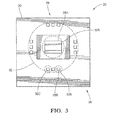
- Figs. 2 and 3 illustrate non-limiting details of the system 20.
- the system 20 includes a lens 24 configured to direct light from a field-of-view 22 toward a focal plane 26 of the lens.
- the field-of-view 22 is typically cone shaped and defined by a viewing angle of the lens 24.
- the lens 24 in this example has four aspherical glass elements configured to provide an effective focal length of 4.8mm and a maximum field of view (i.e. the viewing angle of the field-of-view 22) of 64 degrees.
- the system 20 also includes a plurality of optoelectronic devices 28 arranged proximate to the focal plane 26.
- the plurality of optoelectronic devices 28 may be attached to a printed circuit board 30, as will be recognized by those in the art.
- a key cost saving aspect of the system 20 described herein is that all of the plurality of optoelectronic devices 28 receive light through the lens 24. That is, the lens 24 is shared by all of the plurality of optoelectronic devices 28 which are located within a projection area 32 of the lens 24, and on or near to the focal plane 26.
- the projection area 32 is also known as the "image circle" by those in the art.
- each of the plurality of optoelectronic devices 28 occupies a different region of the projection area 32 on the focal plane 26, it will be recognized that each of the plurality of optoelectronic devices 28 will receive light from a different portion of the field-of-view 22.
- the plurality of optoelectronic devices 28 may include a first optoelectronic device 28A operable to detect an image from a first portion 34 of the field-of-view 22 which is directed onto a first region 32A of the projection area 32 where the first optoelectronic device 28A resides.
- Imaging devices capable of creating video signals based on an image present on the imaging device are well known and commercially available.
- the first optoelectronic device 28A is a model OV10626 imager from OmniVision Inc. with offices in Santa Clara, California, USA.
- the system 20 also includes a second optoelectronic device 28B operable to detect light from a second portion 36 of the field-of-view 22 that is distinct from the first portion 34 and is directed into a second region 32B of the projection area 32 where the second optoelectronic device 28B resides.
- the second optoelectronic device 28B is typically characterized as more of a light sensor than an imaging device. That is, the second optoelectronic device 28B does not generate a signal indicative of an image in the traditional sense, but rather provides an indication of the intensity and/or spectral composition of the light detected by the second optoelectronic device 28B. Specific examples of to second optoelectronic device 28B that provide particular functions to the system 20 are provided below.
- the system 20 advantageously includes an optical device 40 configured to direct light from outside the field-of-view 22 toward the second portion 36.
- the optical device 40 is in the form of an annular ring configured to cooperate with the perimeter of the lens 24 to capture light from outside of the field-of-view 22.
- the annular ring the optical device 40
- the lens 24 would only receive light from the area bounded by the viewing angle of the lens 24 by itself, i.e. the natural or unassisted field-of-view (the field-of-view 22) of the lens 24.
- the first portion 34 of the field-of-view 22 is smaller than the field-of-view 22.
- an inexpensive optical device such as an annular ring
- the effective field-of-view of the system can be expanded, the advantages of which will become apparent in the description below.
- a suitable example of the optical device 40 is an annular ring formed of N-BK7 optical glass material from Schott and is comparable to a diverging meniscus lens with an inner radius of 4.4mm and an outer radius of 10.4 mm.
- the central portion or core is removed to create a ring to provide the lens 24 an unobstructed view of the first portion 34.
- the cross-section profile of the annular ring (the optical device 40) is shown as being constant about the ring, this is not a requirement. That is, it is recognized that the cross-section profile could be varied about the optical device so that the direction and/or scope of light captured by the optical device 40 from outside the field-of-view 22 and directed into the second portion 36 varies about the optical device 40.
- the optical device could be a mirror, a prism, or a combination of mirrors and prisms arranged to direct light from outside the field-of-view 22 and into the second portion 36.
- a blind zone 42 may be created between the first portion 34 and the second portion 36. That is, the lens 24 and the optical device 40 cooperate to create the blind zone 42 between the first portion 34 and the second portion 36 such that light emanating from the blind zone 42 does not reach the lens 24 or the projection area 32, at least not directly. It is recognized that the complexity and cost of the lens 24 could be increased to increase viewing angle of the lens 24 that defines the field-of-view 22, which could avoid creating the blind zone 42. However, the total cost of the system 20 can be reduced by using a less expensive version of lens 24 in combination with the optical device 40 since, as will become apparent in the description below, the creation of the blind zone 42 does not inhibit the desired operation of the system 20 described herein.
- the second optoelectronic device 28B and the optical device 40 cooperate to form a rain sensor for detecting moisture 44 on the window 12.
- the moisture 44 is illustrated as a well-defined droplet only for the purpose of simplifying the explanation.
- optical rain sensors for windshields are commercially available and the principle of operation is known.
- such optical rain sensors are capable of detecting mist or other fine condensation on a windshield of a vehicle.
- a suitable example of the second optoelectronic device 28B to form a rain sensor is part number TEMD7100X01 from Vishay with offices in Shelton, Connecticut, USA.
- the system 20 may include a light source, such as a near-infrared (NIR) light source to illuminate the moisture 44 and thereby assist the system 20 to detect the moisture 44 on the window.
- a light source such as a near-infrared (NIR) light source to illuminate the moisture 44 and thereby assist the system 20 to detect the moisture 44 on the window.
- the system may include an infrared light source 46 configured emit light toward the window 12 where the rain sensor is detecting moisture on the window 12, where the detection is based on signals from the second optoelectronic device 28B.
- the infrared light source 46 is typically located within a housing (not shown) that encompasses the lens 24 and other related parts of the system 20, and positioned so that the incidence angle of light from the infrared light source 46 at the moisture 44 matches the incidence angle of light reflected by the window in the absence of the moisture 44.
- the system 20 may include a prism 48 configured to direct (i.e. bend or refract) light that was emitted by the infrared light source 46 and reflected by the window 12 toward the optical device 40.
- the system 20 may include one or more mirrors (not shown) that may be attached to the housing or elsewhere to assist with directing light from the infrared light source 46 toward the window 12, or light from outside the field-of-view 22 toward the plurality of optoelectronic devices 28.
- the second optoelectronic device 28B and the optical device 40 cooperate to form an ambient light sensor for controlling illuminated devices (e.g. an illuminated instrument display) on the vehicle based on the intensity of ambient light 50 impinging on the window 12.
- illuminated devices e.g. an illuminated instrument display
- a suitable example of the second optoelectronic device 28B to form an ambient light sensor is part number TEMD7000X01 from Vishay with offices in Shelton, Connecticut, USA.
- the system 20 may include a third optoelectronic device 28C operable to detect light via a third portion (not show but could be part of the second portion 36) of the field-of-view 22 which is directed onto a third region 32C of the projection area 32 distinct from the first region 32A and the second region 32B, and where the third optoelectronic device 28C resides. While not specifically illustrated, it is understood that the third portion may be distinct from the first portion 34 and the second portion 36. Accordingly, the optical device 40 may be further configured to direct light from outside the field-of-view 22 into the third portion.
- the system 20 may then be equipped with both a rain sensor and an ambient light sensor.
- the second optoelectronic device 28B and the optical device 40 cooperate to form a rain sensor for detecting moisture on the window 12
- the third optoelectronic device 28C and the optical device 40 cooperate to form an ambient light sensor for controlling illuminated devices on the vehicle 10.
- an optical sensor system (the system 20) is provided.
- the system uses the excess of the field-of-view 22 of the lens 24 that is available within the projected area 32 but not needed by the vision sensor to detect an image from a first portion 34 to place a rain sensor and/or daylight/ambient light sensor and/or other sensors around first optoelectronic device 28A.
- the system may include a NIR LED source (the infrared light source 46) operated by a continuous, pulsed, sine wave, or other signal and used at either TIR (total internal reflection) angle or incident to the window 12 directed to the edge of the field.
- the second optoelectronic device 28B may also include a narrow band NIR filter (not shown) to diminish noise from sun light and other ambient lightings on the road.
- the economic efficiency of the system 20 is improved as the image, rain and daylight sensors share the lens 24. That is, the rain sensor and daylight sensors are located on a shared circuit board and receive light thru same optical system within the same light shield enclosure. This allows for flexibility in design for various applications when compared to traditional or wafer level camera assemblies. This avoids the additional footprint on windscreen arising from separate sensors for rain and light sensing.
Abstract
Description
- This disclosure generally relates to a vehicle optical sensor system, and more particularly relates to an optical sensor system with multiple optoelectronic devices receiving images through a shared lens, and an optical device that expands the effective field-of-view of the lens.
- Optical sensor systems are frequently used in automobiles and other vehicles to provide images of areas around the vehicle. In some instances, these images are used by various vehicle warning and control systems. In the example of forward looking optical sensor systems, the images provided by the sensor may be used as inputs for collision avoidance, lane departure detection, forward collision warning, side warning, adaptive cruise control, night vision, headlight control, rain sensing systems and others. Typically, a forward looking optical sensor system is located behind the windshield near the rear view mirror to obtain a view of the road ahead which is similar to the driver's view. Optical sensor systems may also be used to view the area behind a vehicle for backing up, trailer towing, rearward collision warning, and rear blind zone warning systems. Additionally, optical sensor systems may be used to determine occupant position for restraint systems, rear seat occupant monitoring, or security and intrusion detection systems. Other examples of optical sensor systems include a rain sensor that optically detects the presence of moisture (e.g. rain drops or condensation) on the windshield, and an ambient light sensor that determines ambient lighting conditions outside the vehicle so, for example, the brightness of a display inside the vehicle can be varied to be readily viewable during various ambient lighting conditions.
- The cost of individual sensor systems for each of these vehicle warning or control systems, plus the challenges of efficiently packaging multiple optical sensor systems in a vehicle make it desirable to use a single sensor system to provide images or signals for multiple vehicle warning and control systems. Unfortunately, performance tradeoffs exist when using a single optical sensor system due to light sensitivity, spectrum sensitivity, and field-of-view requirements specific to each vehicle warning and control system. These performance tradeoffs have previously precluded optimum performance for every vehicle warning and control system.
- For example, a night vision system may require an optical sensor system with high light sensitivity because of the need to sense contrast of objects at long ranges with very little active illumination. In contrast, a lane departure system may accommodate an optical sensor system with lower light sensitivity because daylight or headlights (at closer ranges) provide sufficient lighting.
- Light sensitivity is primarily determined by the pixel size of the optoelectronic device used in the optical sensor system to convert light to an electrical signal; a larger pixel has more area available for photons to strike the pixel and be absorbed. As used herein, an optoelectronic device is a component of an optical sensor system that may be operable to generate a video signal. However, a larger pixel size requires a larger optoelectronic device for equivalent pixel resolution. Light sensitivity for a given pixel size may be improved by increasing the exposure time. However, longer exposure time will decrease the frame rate of the images. Additionally, light sensitivity can be increased by using a larger aperture lens to allow more light to fall on the pixels of the sensor. However, a larger aperture usually requires a larger lens, which increases the packaging size of the optical sensor system.
- Different vehicle warning and control systems may also require an optical sensor system with different spectrum sensitivity. For example a tail light detection system may require sensitivity to red light, a lane departure detection system may require sensitivity to yellow light, and a night vision system may require sensitivity to infrared light. There are performance tradeoffs that may be required if a single optical sensor system is used with all three of these vehicle warning and control systems.
- Different vehicle warning and control systems may also require an optical sensor system with a different field-of-view. For example, a rain detection system may need a wide field-of-view while an adaptive cruise control system may need a narrower field-of-view. Again, using a single optical sensor system may require performance tradeoffs.
- In accordance with one embodiment, an optical sensor system adapted to operate through a window of a vehicle is provided. The system includes a lens, a plurality of optoelectronic devices, and an optical device. The lens is configured to direct light from a field-of-view toward a focal plane. The plurality of optoelectronic devices are arranged proximate to the focal plane. The plurality of optoelectronic devices includes a first optoelectronic device operable to detect an image from a first portion of the field-of-view, and a second optoelectronic device operable to detect light from a second portion of the field-of-view distinct from the first portion. The optical device is configured to direct light from outside the field-of-view toward the second portion.
- In one embodiment, the second optoelectronic device and the optical device cooperate to form a rain sensor for detecting moisture on the window.
- In another embodiment, the second optoelectronic device and the optical device cooperate to form an ambient light sensor for controlling illuminated devices on the vehicle.
- Further features and advantages will appear more clearly on a reading of the following detailed description of the preferred embodiment, which is given by way of non-limiting example only and with reference to the accompanying drawings.
- The present invention will now be described, by way of example with reference to the accompanying drawings, in which:
-
Fig. 1 is an illustration of a field-of-view about a vehicle of an optical sensor system in accordance with one embodiment; -
Fig. 2 is a side-view illustration of part of the optical sensor system ofFig. 1 in accordance with one embodiment; and -
Fig. 3 is a front view illustration of part of the optical sensor system ofFig. 1 in accordance with one embodiment. -
Fig. 1 illustrates a non-limiting example of avehicle 10 equipped with an optical sensor system, hereafter referred to as thesystem 20, that provides information based on images and lighting about thevehicle 10. Thesystem 20 is adapted to operate (i.e. look) through awindow 12 of the vehicle. Thesystem 20 is generally positioned on thevehicle 10 to observe a field-of-view 22 about thevehicle 10. The field-of-view 22 is illustrated as being forward of thevehicle 10 for detecting objects in or near the travel path of thevehicle 10, but may also be directed toward an area beside thevehicle 10 to detect objects such as other vehicles in adjacent lanes. Alternatively, the field-of-view 22 may be behind thevehicle 10 to detect, for example, objects behind thevehicle 10 while backing up or monitoring a trailer while towing. The field-of-view 22 may also include an area of the interior of thevehicle 10, for example to detect whether occupants are in a proper position to active a supplemental restraint system, such as an air bag, or to monitor passengers in the rear seats. -
Figs. 2 and3 illustrate non-limiting details of thesystem 20. Thesystem 20 includes alens 24 configured to direct light from a field-of-view 22 toward afocal plane 26 of the lens. The field-of-view 22 is typically cone shaped and defined by a viewing angle of thelens 24. By way of example and not limitation, thelens 24 in this example has four aspherical glass elements configured to provide an effective focal length of 4.8mm and a maximum field of view (i.e. the viewing angle of the field-of-view 22) of 64 degrees. - The
system 20 also includes a plurality ofoptoelectronic devices 28 arranged proximate to thefocal plane 26. The plurality ofoptoelectronic devices 28 may be attached to a printedcircuit board 30, as will be recognized by those in the art. A key cost saving aspect of thesystem 20 described herein is that all of the plurality ofoptoelectronic devices 28 receive light through thelens 24. That is, thelens 24 is shared by all of the plurality ofoptoelectronic devices 28 which are located within aprojection area 32 of thelens 24, and on or near to thefocal plane 26. Theprojection area 32 is also known as the "image circle" by those in the art. However, as each of the plurality ofoptoelectronic devices 28 occupies a different region of theprojection area 32 on thefocal plane 26, it will be recognized that each of the plurality ofoptoelectronic devices 28 will receive light from a different portion of the field-of-view 22. - By way of example and not limitation, the plurality of
optoelectronic devices 28 may include a firstoptoelectronic device 28A operable to detect an image from afirst portion 34 of the field-of-view 22 which is directed onto a first region 32A of theprojection area 32 where the firstoptoelectronic device 28A resides. Imaging devices capable of creating video signals based on an image present on the imaging device are well known and commercially available. In this non-limiting example, the firstoptoelectronic device 28A is a model OV10626 imager from OmniVision Inc. with offices in Santa Clara, California, USA. - The
system 20 also includes a secondoptoelectronic device 28B operable to detect light from asecond portion 36 of the field-of-view 22 that is distinct from thefirst portion 34 and is directed into asecond region 32B of theprojection area 32 where the secondoptoelectronic device 28B resides. The secondoptoelectronic device 28B is typically characterized as more of a light sensor than an imaging device. That is, the secondoptoelectronic device 28B does not generate a signal indicative of an image in the traditional sense, but rather provides an indication of the intensity and/or spectral composition of the light detected by the secondoptoelectronic device 28B. Specific examples of to secondoptoelectronic device 28B that provide particular functions to thesystem 20 are provided below. - The
system 20 advantageously includes anoptical device 40 configured to direct light from outside the field-of-view 22 toward thesecond portion 36. In this example theoptical device 40 is in the form of an annular ring configured to cooperate with the perimeter of thelens 24 to capture light from outside of the field-of-view 22. In other words, if the annular ring (the optical device 40) was removed, thelens 24 would only receive light from the area bounded by the viewing angle of thelens 24 by itself, i.e. the natural or unassisted field-of-view (the field-of-view 22) of thelens 24. As such, thefirst portion 34 of the field-of-view 22 is smaller than the field-of-view 22. However, with the addition of an inexpensive optical device such as an annular ring, the effective field-of-view of the system can be expanded, the advantages of which will become apparent in the description below. - A suitable example of the
optical device 40 is an annular ring formed of N-BK7 optical glass material from Schott and is comparable to a diverging meniscus lens with an inner radius of 4.4mm and an outer radius of 10.4 mm. The central portion or core is removed to create a ring to provide thelens 24 an unobstructed view of thefirst portion 34. While the cross-section profile of the annular ring (the optical device 40) is shown as being constant about the ring, this is not a requirement. That is, it is recognized that the cross-section profile could be varied about the optical device so that the direction and/or scope of light captured by theoptical device 40 from outside the field-of-view 22 and directed into thesecond portion 36 varies about theoptical device 40. Alternatively, the optical device could be a mirror, a prism, or a combination of mirrors and prisms arranged to direct light from outside the field-of-view 22 and into thesecond portion 36. - An effect of adding the
optical device 40 is that ablind zone 42 may be created between thefirst portion 34 and thesecond portion 36. That is, thelens 24 and theoptical device 40 cooperate to create theblind zone 42 between thefirst portion 34 and thesecond portion 36 such that light emanating from theblind zone 42 does not reach thelens 24 or theprojection area 32, at least not directly. It is recognized that the complexity and cost of thelens 24 could be increased to increase viewing angle of thelens 24 that defines the field-of-view 22, which could avoid creating theblind zone 42. However, the total cost of thesystem 20 can be reduced by using a less expensive version oflens 24 in combination with theoptical device 40 since, as will become apparent in the description below, the creation of theblind zone 42 does not inhibit the desired operation of thesystem 20 described herein. - In one embodiment, the second
optoelectronic device 28B and theoptical device 40 cooperate to form a rain sensor for detectingmoisture 44 on thewindow 12. Themoisture 44 is illustrated as a well-defined droplet only for the purpose of simplifying the explanation. It is recognized that optical rain sensors for windshields are commercially available and the principle of operation is known. For example, it is known that such optical rain sensors are capable of detecting mist or other fine condensation on a windshield of a vehicle. By way of example and not limitation, a suitable example of the secondoptoelectronic device 28B to form a rain sensor is part number TEMD7100X01 from Vishay with offices in Shelton, Connecticut, USA. - The
system 20 may include a light source, such as a near-infrared (NIR) light source to illuminate themoisture 44 and thereby assist thesystem 20 to detect themoisture 44 on the window. That is, the system may include an infraredlight source 46 configured emit light toward thewindow 12 where the rain sensor is detecting moisture on thewindow 12, where the detection is based on signals from the secondoptoelectronic device 28B. The infraredlight source 46 is typically located within a housing (not shown) that encompasses thelens 24 and other related parts of thesystem 20, and positioned so that the incidence angle of light from the infraredlight source 46 at themoisture 44 matches the incidence angle of light reflected by the window in the absence of themoisture 44. - If the preferred angle of incidence to the
window 12 makes the preferred orientation for thesecond portion 36 of the field-of-view 22 inconvenient for packaging thesystem 20, or makes the preferred location or orientation of theoptical device 40 inconvenient, thesystem 20 may include aprism 48 configured to direct (i.e. bend or refract) light that was emitted by the infraredlight source 46 and reflected by thewindow 12 toward theoptical device 40. Alternatively, or in addition, thesystem 20 may include one or more mirrors (not shown) that may be attached to the housing or elsewhere to assist with directing light from the infraredlight source 46 toward thewindow 12, or light from outside the field-of-view 22 toward the plurality ofoptoelectronic devices 28. - In one embodiment of the
system 20, the secondoptoelectronic device 28B and theoptical device 40 cooperate to form an ambient light sensor for controlling illuminated devices (e.g. an illuminated instrument display) on the vehicle based on the intensity of ambient light 50 impinging on thewindow 12. By way of example and not limitation, a suitable example of the secondoptoelectronic device 28B to form an ambient light sensor is part number TEMD7000X01 from Vishay with offices in Shelton, Connecticut, USA. - In another embodiment, the
system 20 may include a thirdoptoelectronic device 28C operable to detect light via a third portion (not show but could be part of the second portion 36) of the field-of-view 22 which is directed onto athird region 32C of theprojection area 32 distinct from the first region 32A and thesecond region 32B, and where the thirdoptoelectronic device 28C resides. While not specifically illustrated, it is understood that the third portion may be distinct from thefirst portion 34 and thesecond portion 36. Accordingly, theoptical device 40 may be further configured to direct light from outside the field-of-view 22 into the third portion. By way of example, thesystem 20 may then be equipped with both a rain sensor and an ambient light sensor. That is, the secondoptoelectronic device 28B and theoptical device 40 cooperate to form a rain sensor for detecting moisture on thewindow 12, and the thirdoptoelectronic device 28C and theoptical device 40 cooperate to form an ambient light sensor for controlling illuminated devices on thevehicle 10. - Accordingly, an optical sensor system (the system 20) is provided. The system uses the excess of the field-of-
view 22 of thelens 24 that is available within the projectedarea 32 but not needed by the vision sensor to detect an image from afirst portion 34 to place a rain sensor and/or daylight/ambient light sensor and/or other sensors around firstoptoelectronic device 28A. The system may include a NIR LED source (the infrared light source 46) operated by a continuous, pulsed, sine wave, or other signal and used at either TIR (total internal reflection) angle or incident to thewindow 12 directed to the edge of the field. The secondoptoelectronic device 28B may also include a narrow band NIR filter (not shown) to diminish noise from sun light and other ambient lightings on the road. In this way, the economic efficiency of thesystem 20 is improved as the image, rain and daylight sensors share thelens 24. That is, the rain sensor and daylight sensors are located on a shared circuit board and receive light thru same optical system within the same light shield enclosure. This allows for flexibility in design for various applications when compared to traditional or wafer level camera assemblies. This avoids the additional footprint on windscreen arising from separate sensors for rain and light sensing. - While this invention has been described in terms of the preferred embodiments thereof, it is not intended to be so limited, but rather only to the extent set forth in the claims that follow.
Claims (7)
- An optical sensor system (20) adapted to operate through a window (12) of a vehicle (10), said optical sensor system (20) comprising:a lens (24) configured to direct light from a field-of-view (22) toward a focal plane (26);a plurality of optoelectronic devices (28) arranged proximate to the focal plane (26), wherein said plurality of optoelectronic devices (28) includes a first optoelectronic device (28A) operable to detect an image from a first portion (34) of the field-of-view (22), and a second optoelectronic device (28B) operable to detect light from a second portion (36) of the field-of-view (22) distinct from the first portion (34); andan optical device (40) configured to direct light from outside the field-of-view (22) toward the second portion (36).
- The system (20) in accordance with claim 1, wherein the lens (24) and the optical device (40) cooperate to create a blind zone (42) between the first portion (34) and the second portion (36).
- The system (20) in accordance with claim 1 or 2, wherein the second optoelectronic device (28B) and the optical device (40) cooperate to form a rain sensor for detecting moisture (44) on the window (12).
- The system (20) in accordance with claim 3, wherein the system (20) includes an infrared light source (46) configured emit light toward the window (12) where the rain sensor is detecting moisture (44) on the window (12).
- The system (20) in accordance with claim 4, wherein the system (20) includes a prism (48) configured to direct light that was emitted by the infrared light source (46) and reflected by the window (12) toward the optical device (40).
- The system (20) in accordance with any one of claims 1 to 5, wherein the second optoelectronic device (28B) and the optical device (40) cooperate to form an ambient light (50) sensor for controlling illuminated devices on the vehicle (10).
- The system (20) in accordance with any one of claims 1 to 6, wherein the system (20) includes a third optoelectronic device (28C) operable to detect light via a third portion of the field-of-view (22) distinct from the first portion (34) and the second portion (36), the optical device (40) is further configured to direct light from outside the field-of-view (22) into the third portion, the second optoelectronic device (28B) and the optical device (40) cooperate to form a rain sensor for detecting moisture (44) on the window (12), and the third optoelectronic device (28C) and the optical device (40) cooperate to form an ambient light (50) sensor for controlling illuminated devices on the vehicle (10).
Applications Claiming Priority (1)
| Application Number | Priority Date | Filing Date | Title |
|---|---|---|---|
| US14/488,741 US9506803B2 (en) | 2014-09-17 | 2014-09-17 | Vehicle optical sensor system |
Publications (2)
| Publication Number | Publication Date |
|---|---|
| EP2999207A1 true EP2999207A1 (en) | 2016-03-23 |
| EP2999207B1 EP2999207B1 (en) | 2018-03-07 |
Family
ID=54012029
Family Applications (1)
| Application Number | Title | Priority Date | Filing Date |
|---|---|---|---|
| EP15182158.4A Active EP2999207B1 (en) | 2014-09-17 | 2015-08-24 | Vehicle optical sensor system |
Country Status (3)
| Country | Link |
|---|---|
| US (1) | US9506803B2 (en) |
| EP (1) | EP2999207B1 (en) |
| CN (1) | CN105450947B (en) |
Cited By (2)
| Publication number | Priority date | Publication date | Assignee | Title |
|---|---|---|---|---|
| EP3226539A1 (en) * | 2016-03-30 | 2017-10-04 | Delphi Technologies, Inc. | Multi-purpose camera device for use on a vehicle |
| US11131857B2 (en) * | 2017-06-26 | 2021-09-28 | Gentex Corporation | Dynamic calibration of optical properties of a dimming element |
Families Citing this family (5)
| Publication number | Priority date | Publication date | Assignee | Title |
|---|---|---|---|---|
| JP6369386B2 (en) * | 2015-04-28 | 2018-08-08 | 株式会社デンソー | Camera device |
| US20170314918A1 (en) * | 2016-01-15 | 2017-11-02 | Fugro Roadware Inc. | High speed stereoscopic pavement surface scanning system and method |
| US10480939B2 (en) * | 2016-01-15 | 2019-11-19 | Fugro Roadware Inc. | High speed stereoscopic pavement surface scanning system and method |
| US10190269B2 (en) * | 2016-01-15 | 2019-01-29 | Fugro Roadware Inc. | High speed stereoscopic pavement surface scanning system and method |
| US10845628B2 (en) * | 2018-11-09 | 2020-11-24 | General Motors Llc | System and method to dim at least a portion of a vehicle window |
Citations (5)
| Publication number | Priority date | Publication date | Assignee | Title |
|---|---|---|---|---|
| EP1580092A2 (en) * | 2004-03-26 | 2005-09-28 | Robert Bosch Gmbh | Camera in a vehicle |
| EP1764835A1 (en) * | 2005-09-19 | 2007-03-21 | CRF Societa'Consortile per Azioni | Multifunctional optical sensor comprising a matrix of photodetectors coupled microlenses |
| US20080283782A1 (en) * | 2006-03-08 | 2008-11-20 | Leopold Kostal Gmbh & Co. Kg | Camera arrangement for a motor vehicle |
| DE102011055928A1 (en) * | 2011-12-01 | 2013-06-06 | Conti Temic Microelectronic Gmbh | Optical device e.g. stereo camera, for driver assistance system for detecting e.g. transport area lying ahead of vehicle, has concave mirror and deflecting prism arranged in optical path of near range radiation from near region |
| DE102012200200A1 (en) * | 2012-01-09 | 2013-07-11 | Robert Bosch Gmbh | Camera system, in particular for a vehicle |
Family Cites Families (8)
| Publication number | Priority date | Publication date | Assignee | Title |
|---|---|---|---|---|
| JP4518007B2 (en) * | 2005-11-21 | 2010-08-04 | 株式会社デンソー | Raindrop sensor |
| JP5084331B2 (en) * | 2007-04-09 | 2012-11-28 | オリンパス株式会社 | Observation optical system |
| JP4678536B2 (en) * | 2007-10-01 | 2011-04-27 | 株式会社デンソー | Illuminance sensor |
| US8922644B2 (en) * | 2010-10-07 | 2014-12-30 | Sony Computer Entertainment Inc. | Tracking head position and orientation |
| US20120314069A1 (en) | 2011-06-08 | 2012-12-13 | Delphi Technologies, Inc. | Vehicle optical sensor system |
| US9487159B2 (en) | 2011-08-02 | 2016-11-08 | Magna Electronics Inc. | Vehicle vision system with camera module mounting bracket |
| US20150085118A1 (en) * | 2011-09-07 | 2015-03-26 | Valeo Schalter Und Sensoren Gmbh | Method and camera assembly for detecting raindrops on a windscreen of a vehicle |
| US8987656B2 (en) * | 2012-10-09 | 2015-03-24 | Sae Magnetics (H.K.) Ltd. | Optical finger navigation device having an integrated ambient light sensor and electronic system comprising the same |
-
2014
- 2014-09-17 US US14/488,741 patent/US9506803B2/en active Active
-
2015
- 2015-08-24 EP EP15182158.4A patent/EP2999207B1/en active Active
- 2015-09-11 CN CN201510578515.4A patent/CN105450947B/en active Active
Patent Citations (5)
| Publication number | Priority date | Publication date | Assignee | Title |
|---|---|---|---|---|
| EP1580092A2 (en) * | 2004-03-26 | 2005-09-28 | Robert Bosch Gmbh | Camera in a vehicle |
| EP1764835A1 (en) * | 2005-09-19 | 2007-03-21 | CRF Societa'Consortile per Azioni | Multifunctional optical sensor comprising a matrix of photodetectors coupled microlenses |
| US20080283782A1 (en) * | 2006-03-08 | 2008-11-20 | Leopold Kostal Gmbh & Co. Kg | Camera arrangement for a motor vehicle |
| DE102011055928A1 (en) * | 2011-12-01 | 2013-06-06 | Conti Temic Microelectronic Gmbh | Optical device e.g. stereo camera, for driver assistance system for detecting e.g. transport area lying ahead of vehicle, has concave mirror and deflecting prism arranged in optical path of near range radiation from near region |
| DE102012200200A1 (en) * | 2012-01-09 | 2013-07-11 | Robert Bosch Gmbh | Camera system, in particular for a vehicle |
Cited By (6)
| Publication number | Priority date | Publication date | Assignee | Title |
|---|---|---|---|---|
| EP3226539A1 (en) * | 2016-03-30 | 2017-10-04 | Delphi Technologies, Inc. | Multi-purpose camera device for use on a vehicle |
| CN107272164A (en) * | 2016-03-30 | 2017-10-20 | 德尔福技术有限公司 | For the multipurpose camera apparatus used on vehicle |
| CN107272164B (en) * | 2016-03-30 | 2022-01-11 | 安波福技术有限公司 | Multipurpose camera device for use on a vehicle |
| US11131857B2 (en) * | 2017-06-26 | 2021-09-28 | Gentex Corporation | Dynamic calibration of optical properties of a dimming element |
| US20220004011A1 (en) * | 2017-06-26 | 2022-01-06 | Gentex Corporation | Dynamic calibration of optical properties of a dimming element |
| US11740479B2 (en) * | 2017-06-26 | 2023-08-29 | Gentex Corporation | Dynamic calibration of optical properties of a dimming element |
Also Published As
| Publication number | Publication date |
|---|---|
| EP2999207B1 (en) | 2018-03-07 |
| CN105450947A (en) | 2016-03-30 |
| CN105450947B (en) | 2020-12-25 |
| US20160076934A1 (en) | 2016-03-17 |
| US9506803B2 (en) | 2016-11-29 |
Similar Documents
| Publication | Publication Date | Title |
|---|---|---|
| EP2999207B1 (en) | Vehicle optical sensor system | |
| US11341671B2 (en) | Vehicular driver monitoring system | |
| US10137842B2 (en) | Camera system for a vehicle | |
| EP2870031B1 (en) | Gated stereo imaging system and method | |
| US8830324B2 (en) | Vehicle monitoring camera and vehicle monitoring camera system | |
| US6603137B2 (en) | Differential imaging rain sensor | |
| CN106488092B (en) | Integrated camera, ambient light detection and rain sensor assembly | |
| US6840342B1 (en) | Sensor device for a motor vehicle used for detecting environmental parameters | |
| US20150070499A1 (en) | Camera system, in particular for a vehicle | |
| US20070069135A1 (en) | Method and device for controlling a radiation source | |
| JP2007114193A (en) | On-board optical sensor device for assisting driving and/or for automatically operating system mounted on automobile | |
| US10112552B2 (en) | Vehicle vision system with camera viewing through windshield | |
| JP6481970B2 (en) | Driver shooting device | |
| EP2869021B1 (en) | Multiple imager vehicle optical sensor system | |
| CN111301302B (en) | Motor vehicle-sensor assembly module | |
| JP2002274258A (en) | Night vision system for automobile | |
| US20160280133A1 (en) | Vehicle vision system with thermal sensor | |
| JP6246932B2 (en) | Lighting to detect raindrops on the window glass using a camera | |
| KR101527810B1 (en) | Infrared Image Pickup Device for Visibility of Road and Image Pickup Method Using the Same | |
| US20200353865A1 (en) | Passenger imaging device | |
| EP3185179A1 (en) | Multiple imager vehicle optical sensor system | |
| US6969855B2 (en) | Active night vision thermal control system | |
| US20160107576A1 (en) | Multiple imager vehicle optical sensor system | |
| EP3428686B1 (en) | A vision system and method for a vehicle | |
| US20230173983A1 (en) | Vehicle Tracking for a Camera Wing System |
Legal Events
| Date | Code | Title | Description |
|---|---|---|---|
| PUAI | Public reference made under article 153(3) epc to a published international application that has entered the european phase |
Free format text: ORIGINAL CODE: 0009012 |
|
| AK | Designated contracting states |
Kind code of ref document: A1 Designated state(s): AL AT BE BG CH CY CZ DE DK EE ES FI FR GB GR HR HU IE IS IT LI LT LU LV MC MK MT NL NO PL PT RO RS SE SI SK SM TR |
|
| AX | Request for extension of the european patent |
Extension state: BA ME |
|
| 17P | Request for examination filed |
Effective date: 20160923 |
|
| RBV | Designated contracting states (corrected) |
Designated state(s): AL AT BE BG CH CY CZ DE DK EE ES FI FR GB GR HR HU IE IS IT LI LT LU LV MC MK MT NL NO PL PT RO RS SE SI SK SM TR |
|
| 17Q | First examination report despatched |
Effective date: 20170213 |
|
| GRAP | Despatch of communication of intention to grant a patent |
Free format text: ORIGINAL CODE: EPIDOSNIGR1 |
|
| INTG | Intention to grant announced |
Effective date: 20170926 |
|
| RIN1 | Information on inventor provided before grant (corrected) |
Inventor name: MURPHY, MORGAN D. Inventor name: YEO, KOK WEE Inventor name: DEGENKOLB, THOMAS A. Inventor name: LOW, YEW KWANG Inventor name: TAYLOR, RONALD M. Inventor name: EVERLY, WARD K. |
|
| GRAS | Grant fee paid |
Free format text: ORIGINAL CODE: EPIDOSNIGR3 |
|
| GRAA | (expected) grant |
Free format text: ORIGINAL CODE: 0009210 |
|
| AK | Designated contracting states |
Kind code of ref document: B1 Designated state(s): AL AT BE BG CH CY CZ DE DK EE ES FI FR GB GR HR HU IE IS IT LI LT LU LV MC MK MT NL NO PL PT RO RS SE SI SK SM TR |
|
| REG | Reference to a national code |
Ref country code: GB Ref legal event code: FG4D |
|
| REG | Reference to a national code |
Ref country code: CH Ref legal event code: EP Ref country code: AT Ref legal event code: REF Ref document number: 977769 Country of ref document: AT Kind code of ref document: T Effective date: 20180315 |
|
| REG | Reference to a national code |
Ref country code: DE Ref legal event code: R096 Ref document number: 602015008556 Country of ref document: DE |
|
| REG | Reference to a national code |
Ref country code: IE Ref legal event code: FG4D |
|
| REG | Reference to a national code |
Ref country code: NL Ref legal event code: MP Effective date: 20180307 |
|
| REG | Reference to a national code |
Ref country code: LT Ref legal event code: MG4D |
|
| PG25 | Lapsed in a contracting state [announced via postgrant information from national office to epo] |
Ref country code: NO Free format text: LAPSE BECAUSE OF FAILURE TO SUBMIT A TRANSLATION OF THE DESCRIPTION OR TO PAY THE FEE WITHIN THE PRESCRIBED TIME-LIMIT Effective date: 20180607 Ref country code: FI Free format text: LAPSE BECAUSE OF FAILURE TO SUBMIT A TRANSLATION OF THE DESCRIPTION OR TO PAY THE FEE WITHIN THE PRESCRIBED TIME-LIMIT Effective date: 20180307 Ref country code: CY Free format text: LAPSE BECAUSE OF FAILURE TO SUBMIT A TRANSLATION OF THE DESCRIPTION OR TO PAY THE FEE WITHIN THE PRESCRIBED TIME-LIMIT Effective date: 20180307 Ref country code: ES Free format text: LAPSE BECAUSE OF FAILURE TO SUBMIT A TRANSLATION OF THE DESCRIPTION OR TO PAY THE FEE WITHIN THE PRESCRIBED TIME-LIMIT Effective date: 20180307 Ref country code: LT Free format text: LAPSE BECAUSE OF FAILURE TO SUBMIT A TRANSLATION OF THE DESCRIPTION OR TO PAY THE FEE WITHIN THE PRESCRIBED TIME-LIMIT Effective date: 20180307 Ref country code: HR Free format text: LAPSE BECAUSE OF FAILURE TO SUBMIT A TRANSLATION OF THE DESCRIPTION OR TO PAY THE FEE WITHIN THE PRESCRIBED TIME-LIMIT Effective date: 20180307 |
|
| REG | Reference to a national code |
Ref country code: AT Ref legal event code: MK05 Ref document number: 977769 Country of ref document: AT Kind code of ref document: T Effective date: 20180307 |
|
| REG | Reference to a national code |
Ref country code: FR Ref legal event code: PLFP Year of fee payment: 4 |
|
| PG25 | Lapsed in a contracting state [announced via postgrant information from national office to epo] |
Ref country code: GR Free format text: LAPSE BECAUSE OF FAILURE TO SUBMIT A TRANSLATION OF THE DESCRIPTION OR TO PAY THE FEE WITHIN THE PRESCRIBED TIME-LIMIT Effective date: 20180608 Ref country code: BG Free format text: LAPSE BECAUSE OF FAILURE TO SUBMIT A TRANSLATION OF THE DESCRIPTION OR TO PAY THE FEE WITHIN THE PRESCRIBED TIME-LIMIT Effective date: 20180607 Ref country code: RS Free format text: LAPSE BECAUSE OF FAILURE TO SUBMIT A TRANSLATION OF THE DESCRIPTION OR TO PAY THE FEE WITHIN THE PRESCRIBED TIME-LIMIT Effective date: 20180307 Ref country code: SE Free format text: LAPSE BECAUSE OF FAILURE TO SUBMIT A TRANSLATION OF THE DESCRIPTION OR TO PAY THE FEE WITHIN THE PRESCRIBED TIME-LIMIT Effective date: 20180307 Ref country code: LV Free format text: LAPSE BECAUSE OF FAILURE TO SUBMIT A TRANSLATION OF THE DESCRIPTION OR TO PAY THE FEE WITHIN THE PRESCRIBED TIME-LIMIT Effective date: 20180307 |
|
| PG25 | Lapsed in a contracting state [announced via postgrant information from national office to epo] |
Ref country code: PL Free format text: LAPSE BECAUSE OF FAILURE TO SUBMIT A TRANSLATION OF THE DESCRIPTION OR TO PAY THE FEE WITHIN THE PRESCRIBED TIME-LIMIT Effective date: 20180307 Ref country code: EE Free format text: LAPSE BECAUSE OF FAILURE TO SUBMIT A TRANSLATION OF THE DESCRIPTION OR TO PAY THE FEE WITHIN THE PRESCRIBED TIME-LIMIT Effective date: 20180307 Ref country code: RO Free format text: LAPSE BECAUSE OF FAILURE TO SUBMIT A TRANSLATION OF THE DESCRIPTION OR TO PAY THE FEE WITHIN THE PRESCRIBED TIME-LIMIT Effective date: 20180307 Ref country code: NL Free format text: LAPSE BECAUSE OF FAILURE TO SUBMIT A TRANSLATION OF THE DESCRIPTION OR TO PAY THE FEE WITHIN THE PRESCRIBED TIME-LIMIT Effective date: 20180307 Ref country code: IT Free format text: LAPSE BECAUSE OF FAILURE TO SUBMIT A TRANSLATION OF THE DESCRIPTION OR TO PAY THE FEE WITHIN THE PRESCRIBED TIME-LIMIT Effective date: 20180307 Ref country code: AL Free format text: LAPSE BECAUSE OF FAILURE TO SUBMIT A TRANSLATION OF THE DESCRIPTION OR TO PAY THE FEE WITHIN THE PRESCRIBED TIME-LIMIT Effective date: 20180307 |
|
| PG25 | Lapsed in a contracting state [announced via postgrant information from national office to epo] |
Ref country code: SK Free format text: LAPSE BECAUSE OF FAILURE TO SUBMIT A TRANSLATION OF THE DESCRIPTION OR TO PAY THE FEE WITHIN THE PRESCRIBED TIME-LIMIT Effective date: 20180307 Ref country code: SM Free format text: LAPSE BECAUSE OF FAILURE TO SUBMIT A TRANSLATION OF THE DESCRIPTION OR TO PAY THE FEE WITHIN THE PRESCRIBED TIME-LIMIT Effective date: 20180307 Ref country code: AT Free format text: LAPSE BECAUSE OF FAILURE TO SUBMIT A TRANSLATION OF THE DESCRIPTION OR TO PAY THE FEE WITHIN THE PRESCRIBED TIME-LIMIT Effective date: 20180307 Ref country code: CZ Free format text: LAPSE BECAUSE OF FAILURE TO SUBMIT A TRANSLATION OF THE DESCRIPTION OR TO PAY THE FEE WITHIN THE PRESCRIBED TIME-LIMIT Effective date: 20180307 |
|
| REG | Reference to a national code |
Ref country code: DE Ref legal event code: R081 Ref document number: 602015008556 Country of ref document: DE Owner name: APTIV TECHNOLOGIES LIMITED, BB Free format text: FORMER OWNER: DELPHI TECHNOLOGIES, INC., TROY, MICH., US |
|
| REG | Reference to a national code |
Ref country code: DE Ref legal event code: R097 Ref document number: 602015008556 Country of ref document: DE |
|
| PG25 | Lapsed in a contracting state [announced via postgrant information from national office to epo] |
Ref country code: PT Free format text: LAPSE BECAUSE OF FAILURE TO SUBMIT A TRANSLATION OF THE DESCRIPTION OR TO PAY THE FEE WITHIN THE PRESCRIBED TIME-LIMIT Effective date: 20180709 |
|
| PLBE | No opposition filed within time limit |
Free format text: ORIGINAL CODE: 0009261 |
|
| STAA | Information on the status of an ep patent application or granted ep patent |
Free format text: STATUS: NO OPPOSITION FILED WITHIN TIME LIMIT |
|
| PG25 | Lapsed in a contracting state [announced via postgrant information from national office to epo] |
Ref country code: DK Free format text: LAPSE BECAUSE OF FAILURE TO SUBMIT A TRANSLATION OF THE DESCRIPTION OR TO PAY THE FEE WITHIN THE PRESCRIBED TIME-LIMIT Effective date: 20180307 |
|
| 26N | No opposition filed |
Effective date: 20181210 |
|
| REG | Reference to a national code |
Ref country code: GB Ref legal event code: 732E Free format text: REGISTERED BETWEEN 20190117 AND 20190123 |
|
| REG | Reference to a national code |
Ref country code: GB Ref legal event code: 732E Free format text: REGISTERED BETWEEN 20190124 AND 20190130 |
|
| PG25 | Lapsed in a contracting state [announced via postgrant information from national office to epo] |
Ref country code: SI Free format text: LAPSE BECAUSE OF FAILURE TO SUBMIT A TRANSLATION OF THE DESCRIPTION OR TO PAY THE FEE WITHIN THE PRESCRIBED TIME-LIMIT Effective date: 20180307 |
|
| PG25 | Lapsed in a contracting state [announced via postgrant information from national office to epo] |
Ref country code: MC Free format text: LAPSE BECAUSE OF FAILURE TO SUBMIT A TRANSLATION OF THE DESCRIPTION OR TO PAY THE FEE WITHIN THE PRESCRIBED TIME-LIMIT Effective date: 20180307 |
|
| REG | Reference to a national code |
Ref country code: CH Ref legal event code: PL |
|
| PG25 | Lapsed in a contracting state [announced via postgrant information from national office to epo] |
Ref country code: LU Free format text: LAPSE BECAUSE OF NON-PAYMENT OF DUE FEES Effective date: 20180824 Ref country code: CH Free format text: LAPSE BECAUSE OF NON-PAYMENT OF DUE FEES Effective date: 20180831 Ref country code: LI Free format text: LAPSE BECAUSE OF NON-PAYMENT OF DUE FEES Effective date: 20180831 |
|
| REG | Reference to a national code |
Ref country code: BE Ref legal event code: MM Effective date: 20180831 |
|
| PG25 | Lapsed in a contracting state [announced via postgrant information from national office to epo] |
Ref country code: BE Free format text: LAPSE BECAUSE OF NON-PAYMENT OF DUE FEES Effective date: 20180831 |
|
| PG25 | Lapsed in a contracting state [announced via postgrant information from national office to epo] |
Ref country code: MT Free format text: LAPSE BECAUSE OF NON-PAYMENT OF DUE FEES Effective date: 20180824 |
|
| PG25 | Lapsed in a contracting state [announced via postgrant information from national office to epo] |
Ref country code: TR Free format text: LAPSE BECAUSE OF FAILURE TO SUBMIT A TRANSLATION OF THE DESCRIPTION OR TO PAY THE FEE WITHIN THE PRESCRIBED TIME-LIMIT Effective date: 20180307 |
|
| PG25 | Lapsed in a contracting state [announced via postgrant information from national office to epo] |
Ref country code: MK Free format text: LAPSE BECAUSE OF NON-PAYMENT OF DUE FEES Effective date: 20180307 Ref country code: HU Free format text: LAPSE BECAUSE OF FAILURE TO SUBMIT A TRANSLATION OF THE DESCRIPTION OR TO PAY THE FEE WITHIN THE PRESCRIBED TIME-LIMIT; INVALID AB INITIO Effective date: 20150824 Ref country code: IE Free format text: LAPSE BECAUSE OF NON-PAYMENT OF DUE FEES Effective date: 20180824 |
|
| PG25 | Lapsed in a contracting state [announced via postgrant information from national office to epo] |
Ref country code: IS Free format text: LAPSE BECAUSE OF FAILURE TO SUBMIT A TRANSLATION OF THE DESCRIPTION OR TO PAY THE FEE WITHIN THE PRESCRIBED TIME-LIMIT Effective date: 20180707 |
|
| REG | Reference to a national code |
Ref country code: DE Ref legal event code: R079 Ref document number: 602015008556 Country of ref document: DE Free format text: PREVIOUS MAIN CLASS: H04N0005225000 Ipc: H04N0023000000 |
|
| P01 | Opt-out of the competence of the unified patent court (upc) registered |
Effective date: 20230425 |
|
| PGFP | Annual fee paid to national office [announced via postgrant information from national office to epo] |
Ref country code: GB Payment date: 20230823 Year of fee payment: 9 |
|
| PGFP | Annual fee paid to national office [announced via postgrant information from national office to epo] |
Ref country code: FR Payment date: 20230821 Year of fee payment: 9 Ref country code: DE Payment date: 20230817 Year of fee payment: 9 |