EP3739688A1 - Elektrodrahtverbinder - Google Patents
Elektrodrahtverbinder Download PDFInfo
- Publication number
- EP3739688A1 EP3739688A1 EP19174654.4A EP19174654A EP3739688A1 EP 3739688 A1 EP3739688 A1 EP 3739688A1 EP 19174654 A EP19174654 A EP 19174654A EP 3739688 A1 EP3739688 A1 EP 3739688A1
- Authority
- EP
- European Patent Office
- Prior art keywords
- wire
- electric wire
- housing
- housing cover
- wire connector
- Prior art date
- Legal status (The legal status is an assumption and is not a legal conclusion. Google has not performed a legal analysis and makes no representation as to the accuracy of the status listed.)
- Granted
Links
- 238000003780 insertion Methods 0.000 claims abstract description 29
- 230000037431 insertion Effects 0.000 claims abstract description 29
- 230000014759 maintenance of location Effects 0.000 claims description 33
- 230000004888 barrier function Effects 0.000 claims description 27
- 239000003566 sealing material Substances 0.000 claims description 21
- 238000009413 insulation Methods 0.000 claims description 7
- 238000005520 cutting process Methods 0.000 claims description 6
- 238000009434 installation Methods 0.000 claims description 6
- 238000006073 displacement reaction Methods 0.000 claims description 4
- 239000004020 conductor Substances 0.000 description 10
- 239000000463 material Substances 0.000 description 9
- 238000004519 manufacturing process Methods 0.000 description 5
- 229920003023 plastic Polymers 0.000 description 5
- 238000010521 absorption reaction Methods 0.000 description 4
- 238000005452 bending Methods 0.000 description 4
- 230000000295 complement effect Effects 0.000 description 4
- 238000004880 explosion Methods 0.000 description 4
- 238000001746 injection moulding Methods 0.000 description 4
- 239000012528 membrane Substances 0.000 description 4
- 229920001955 polyphenylene ether Polymers 0.000 description 4
- 230000000694 effects Effects 0.000 description 3
- 238000011900 installation process Methods 0.000 description 3
- RYGMFSIKBFXOCR-UHFFFAOYSA-N Copper Chemical compound [Cu] RYGMFSIKBFXOCR-UHFFFAOYSA-N 0.000 description 2
- 239000012141 concentrate Substances 0.000 description 2
- 229910052802 copper Inorganic materials 0.000 description 2
- 239000010949 copper Substances 0.000 description 2
- 239000002184 metal Substances 0.000 description 2
- 229910052751 metal Inorganic materials 0.000 description 2
- 239000002245 particle Substances 0.000 description 2
- 238000007789 sealing Methods 0.000 description 2
- XLYOFNOQVPJJNP-UHFFFAOYSA-N water Substances O XLYOFNOQVPJJNP-UHFFFAOYSA-N 0.000 description 2
- 239000000853 adhesive Substances 0.000 description 1
- 230000001070 adhesive effect Effects 0.000 description 1
- 230000003247 decreasing effect Effects 0.000 description 1
- 239000000428 dust Substances 0.000 description 1
- 230000007613 environmental effect Effects 0.000 description 1
- 230000007257 malfunction Effects 0.000 description 1
- 238000003825 pressing Methods 0.000 description 1
- 238000000926 separation method Methods 0.000 description 1
- 230000000087 stabilizing effect Effects 0.000 description 1
- 210000002105 tongue Anatomy 0.000 description 1
Images


Classifications
-
- H—ELECTRICITY
- H01—ELECTRIC ELEMENTS
- H01R—ELECTRICALLY-CONDUCTIVE CONNECTIONS; STRUCTURAL ASSOCIATIONS OF A PLURALITY OF MUTUALLY-INSULATED ELECTRICAL CONNECTING ELEMENTS; COUPLING DEVICES; CURRENT COLLECTORS
- H01R13/00—Details of coupling devices of the kinds covered by groups H01R12/70 or H01R24/00 - H01R33/00
- H01R13/46—Bases; Cases
- H01R13/502—Bases; Cases composed of different pieces
- H01R13/506—Bases; Cases composed of different pieces assembled by snap action of the parts
-
- H—ELECTRICITY
- H01—ELECTRIC ELEMENTS
- H01R—ELECTRICALLY-CONDUCTIVE CONNECTIONS; STRUCTURAL ASSOCIATIONS OF A PLURALITY OF MUTUALLY-INSULATED ELECTRICAL CONNECTING ELEMENTS; COUPLING DEVICES; CURRENT COLLECTORS
- H01R4/00—Electrically-conductive connections between two or more conductive members in direct contact, i.e. touching one another; Means for effecting or maintaining such contact; Electrically-conductive connections having two or more spaced connecting locations for conductors and using contact members penetrating insulation
- H01R4/24—Connections using contact members penetrating or cutting insulation or cable strands
- H01R4/2416—Connections using contact members penetrating or cutting insulation or cable strands the contact members having insulation-cutting edges, e.g. of tuning fork type
- H01R4/242—Connections using contact members penetrating or cutting insulation or cable strands the contact members having insulation-cutting edges, e.g. of tuning fork type the contact members being plates having a single slot
- H01R4/2425—Flat plates, e.g. multi-layered flat plates
- H01R4/2429—Flat plates, e.g. multi-layered flat plates mounted in an insulating base
- H01R4/2433—Flat plates, e.g. multi-layered flat plates mounted in an insulating base one part of the base being movable to push the cable into the slot
-
- H—ELECTRICITY
- H01—ELECTRIC ELEMENTS
- H01R—ELECTRICALLY-CONDUCTIVE CONNECTIONS; STRUCTURAL ASSOCIATIONS OF A PLURALITY OF MUTUALLY-INSULATED ELECTRICAL CONNECTING ELEMENTS; COUPLING DEVICES; CURRENT COLLECTORS
- H01R11/00—Individual connecting elements providing two or more spaced connecting locations for conductive members which are, or may be, thereby interconnected, e.g. end pieces for wires or cables supported by the wire or cable and having means for facilitating electrical connection to some other wire, terminal, or conductive member, blocks of binding posts
- H01R11/03—Individual connecting elements providing two or more spaced connecting locations for conductive members which are, or may be, thereby interconnected, e.g. end pieces for wires or cables supported by the wire or cable and having means for facilitating electrical connection to some other wire, terminal, or conductive member, blocks of binding posts characterised by the relationship between the connecting locations
- H01R11/09—Individual connecting elements providing two or more spaced connecting locations for conductive members which are, or may be, thereby interconnected, e.g. end pieces for wires or cables supported by the wire or cable and having means for facilitating electrical connection to some other wire, terminal, or conductive member, blocks of binding posts characterised by the relationship between the connecting locations the connecting locations being identical
-
- H—ELECTRICITY
- H02—GENERATION; CONVERSION OR DISTRIBUTION OF ELECTRIC POWER
- H02S—GENERATION OF ELECTRIC POWER BY CONVERSION OF INFRARED RADIATION, VISIBLE LIGHT OR ULTRAVIOLET LIGHT, e.g. USING PHOTOVOLTAIC [PV] MODULES
- H02S40/00—Components or accessories in combination with PV modules, not provided for in groups H02S10/00 - H02S30/00
- H02S40/30—Electrical components
- H02S40/36—Electrical components characterised by special electrical interconnection means between two or more PV modules, e.g. electrical module-to-module connection
-
- H—ELECTRICITY
- H01—ELECTRIC ELEMENTS
- H01R—ELECTRICALLY-CONDUCTIVE CONNECTIONS; STRUCTURAL ASSOCIATIONS OF A PLURALITY OF MUTUALLY-INSULATED ELECTRICAL CONNECTING ELEMENTS; COUPLING DEVICES; CURRENT COLLECTORS
- H01R13/00—Details of coupling devices of the kinds covered by groups H01R12/70 or H01R24/00 - H01R33/00
- H01R13/58—Means for relieving strain on wire connection, e.g. cord grip, for avoiding loosening of connections between wires and terminals within a coupling device terminating a cable
- H01R13/5804—Means for relieving strain on wire connection, e.g. cord grip, for avoiding loosening of connections between wires and terminals within a coupling device terminating a cable comprising a separate cable clamping part
- H01R13/5816—Means for relieving strain on wire connection, e.g. cord grip, for avoiding loosening of connections between wires and terminals within a coupling device terminating a cable comprising a separate cable clamping part for cables passing through an aperture in a housing wall, the separate part being captured between cable and contour of aperture
-
- Y—GENERAL TAGGING OF NEW TECHNOLOGICAL DEVELOPMENTS; GENERAL TAGGING OF CROSS-SECTIONAL TECHNOLOGIES SPANNING OVER SEVERAL SECTIONS OF THE IPC; TECHNICAL SUBJECTS COVERED BY FORMER USPC CROSS-REFERENCE ART COLLECTIONS [XRACs] AND DIGESTS
- Y02—TECHNOLOGIES OR APPLICATIONS FOR MITIGATION OR ADAPTATION AGAINST CLIMATE CHANGE
- Y02E—REDUCTION OF GREENHOUSE GAS [GHG] EMISSIONS, RELATED TO ENERGY GENERATION, TRANSMISSION OR DISTRIBUTION
- Y02E10/00—Energy generation through renewable energy sources
- Y02E10/50—Photovoltaic [PV] energy
Definitions
- the invention relates to an electric wire connector for connecting at least two wires.
- Electric wire connectors are used for connecting two or more wires. Usually, each wire is terminated in a separate connector, which are subsequently mated with one another. However, having different connectors for each wire may increase the size and complexity of the system. Furthermore, existing electric wire connectors are not suitable for high wire diameters. In particular, in solar systems, the solar wires have a high outer diameter ranging from 5.5 to 7.5 mm including the jacket. This makes the handling of the wires more troublesome. High bending forces are necessary, in order to terminate a wire ending in the electric wire connector.
- the invention solves the above-mentioned problem by providing an electric wire connector for connecting at least two wires, particularly solar wires.
- the electric wire connector comprises:
- the inventive electric wire connector a single connector is provided for connecting the at least two wires to one another.
- the housing base comprises a compartment for receiving a respective wire.
- the wires can be terminated to the contact terminals, which are each arranged in a compartment and electrically coupled with one another by the electrically conductive member.
- the at least one reception opening is arranged in the housing cover, the housing cover being linearly movable relative to the housing base. Therefore, the whole wire, meaning the part that is inserted through the reception opening into the connector housing and the part of the wire located directly in front of the reception opening outside of the connector housing, can be moved towards the housing base and the contact terminal arranged in the housing base. Consequently, high bending forces can be prevented for terminating the wire.
- the invention can be further improved by the following features, which are independent from one another with respect to their respective technical effects and which can be combined arbitrarily.
- the at least one wire receiving opening may be adaptable to a wide range of wire sizes.
- those wire sizes may have a conductor with an effective cross section of between about 2.5 to about 10 mm 2 and an outer diameter of the wire, i.e. the jacket, may range between about 5.5 to about 7.5 mm.
- the at least one wire receiving opening may comprise a circular cross section in a plane perpendicular to the insertion direction.
- the cross section of the at least one wire receiving opening may be configured for the maximum wire size.
- the cross section can be adapted to the wire size, i.e. if a wire with a small wire size is inserted, the cross section may be reduced to hold the wire securely in the wire receiving opening. This may, for example, be accomplished by providing clamping jaws in the inner surface of the wire receiving opening, which are held radially movable in the wire receiving opening, reducing or increasing the effective cross section of the wire receiving opening.
- At least the at least one wire reception opening may be sealed with a sealing material.
- the sealing material may form a membrane preventing any unwanted particles to enter the housing.
- the sealing material may be prearranged in the at least one wire reception opening before inserting the wire. By inserting the wire, the wire may penetrate through the sealing material creating an effective cross section in the wire receiving opening that corresponds to the effective cross section of the wire itself. Therefore, a standardized sealed electric wire connector may be applicable for different wire sizes.
- the membrane may comprise perforations or cuts separating the membrane into plural segments. The perforations or cuts do not fully penetrate the membrane but will allow a separation of the segments when inserting the wire through the sealing material.
- the sealing material may preferably, in particular in the closed position, essentially fill the entire space within the connector housing. In the closed position, the sealing material may essentially fill all voids within the housing and prevent humidity or dirt from entering the housing.
- the sealing material may preferably be a gel sealing material fulfilling the requirements of an IPX8 standard, meaning that the electric connector is adapted to safely being immersed under water at a certain depth for a certain time.
- the electric connector may be adapted to be submerged 1 m in water for 24 hours.
- the housing cover may be a single part, which covers all compartments and comprises a separate wire reception opening for each wire to be inserted. Thus, all wires may be mounted and are simultaneously terminated onto their corresponding contact terminals when moving the housing cover to the closed position.
- a housing cover may be comprised for each compartment in the housing base.
- the housing covers may particularly be linearly movable relative to the housing base independently to one another, facilitating the installation process. A user may concentrate on terminating one wire at a time.
- the housing covers for each compartment may be separated from one another.
- the housing covers may be structured identically, so that the housing covers may be efficiently produced on a mass scale, for example by injection molding.
- the at least one housing cover may be movable relative to the housing base in a direction essentially perpendicular to the insertion direction.
- the at least one housing cover may be linearly slidable relative to the housing base in a direction essentially perpendicular to the insertion direction.
- the at least two contact terminals may preferably be insulation displacement contacts (in the following, IDC).
- IDC insulation displacement contacts
- IDCs inconvenient processing of the wire, e.g. stripping the wire, prior to termination may be averted.
- the IDC may comprise a slot with cutting edges, adapted to cut through the jacket of the wire and contact the conductor of the wire. The IDC allows for an easy installation process for electrically connecting a cable.
- the at least two contact terminals may be insulation piercing contacts.
- the contacts may comprise spikes, which may penetrate through the wire jacket and contact the conductors.
- a biasing spring may be provided, which is adapted to push the wire against the contacts in the closed state and to ensure that the connection force does not deteriorate over a longer period of operation and/or due to stress, such as vibrations.
- the biasing spring may be arranged in the corresponding housing cover and be adapted to receive and especially retain the wire. By moving the housing cover from the open into the closed position, the biasing spring pushes the wire against the corresponding contact terminal.
- the biasing spring may preferably be arranged opposite the corresponding contact terminal in a motion direction of the housing cover relative to the housing base.
- the biasing spring does not need to be mounted in the housing cover.
- the housing base may encase the IDC and be adapted to slide relative to the IDC when being pushed down by the housing cover.
- the biasing spring may comprise spring tongues adapted to engage complementary-formed notches at least in the closed position to further stabilize the relative position between the IDC and the biasing spring in the closed position.
- the biasing spring may reinforce the contact between the wire conductor and the IDC making the connector suitable for high current connections. With increased contact force, it is also possible to arrange the strands of the wire conductor more tightly. This would lead to a sound pressing force of the conductor against opposing side surfaces of the IDC and a thorough contact of each of the strands against each other within the contact slot on the other hand.
- the at least two contact terminals may preferably be adaptable to a wide range of cable sizes.
- the slot of the IDC may be adaptable to receive different wire sizes, particularly solar wires as specified above. Therefore, a standardized contact terminal may be provided, which can be used for different wire sizes instead of using specific contact terminals for each wire size.
- the slot of the IDC may particularly be arranged essentially perpendicularto the insertion direction and parallel to the motion direction of the housing cover relative to the housing base. Meaning that the wire will be linearly inserted into the slot causing a straight incision of the cutting edges into the wire jacket perpendicular to the longitudinal axis of the wire.
- At least one retention element may be comprised for retaining the wire when inserted into the at least one receiving opening.
- the retention element may preferably be attached to the housing cover.
- the retention element may be adapted to cooperate with the jacket of the wire to be inserted to retain the wire within the housing during the installation process. Therefore, falling out of the wire during installation may be prevented.
- the retention element may preferably be a retention spring that is usually made of a single piece of cut, preferably stamped sheet metal.
- the retention spring may comprise an annular opening for receiving the wire formed on a base.
- spring arms may radially project inwards and may be slightly bent obliquely to the insertion direction to assume an inclination of 10 to 45° to the insertion direction. Due to this inclination, the spring arms define hooks cooperating with the outer circumference of the jacket, which hooks prevent the wire from being drawn out of the housing after insertion of the wire.
- the retention element may further function as a guiding feature, guiding the inserted wire through the housing cover towards an end position.
- the retention element may thus preferably be arranged in the housing cover having an opening coaxially arranged to the at least one reception opening.
- the retention element may preferably be arranged between the at least one reception opening and the biasing spring, guiding the wire to the biasing spring.
- the biasing spring may encompass the wire in an essentially U-shaped manner, so that a crosspiece of the biasing spring pushes the wire towards the IDC in the closed position.
- the retention element may further be adapted to absorb any torsional tension exerted on the wire. Therefore, the torsional tension of the wire is not further transferred to the biasing spring and/or contact terminal.
- the retention element may comprise a slit, in which the wire may be inserted.
- the slit may comprise a widening, which may preferably be circular shaped. The widening may act as torsion absorption features, which absorb forces due to wire torsion resulting in a stable wire termination.
- the retention element may preferably be a loose piece, which can be fixedly mounted in the housing cover.
- the retention element may comprise locking features, which may be interlocked with complementary locking features in the housing cover.
- the retention element may comprise notches, which may be pressed into plastic ribs of the housing cover.
- At least one barrier may be provided.
- the at least one barrier may comprise at least two securing ribs arranged opposite to one another, each forming an end wall of the respective compartment in the insertion direction at least in the open position.
- the securing ribs may be arranged in a space between two ribs of the at least one housing cover.
- the space may preferably be filled with the sealing material, further securing the position of the at least one housing cover and housing base in the insertion direction.
- the distance between the securing ribs may further help ensure that creep and/or clearance requirements are met.
- the at least one barrier may be formed from the same material as the housing.
- the at least one barrier and the housing base may be formed as a single monolithic piece, for example by injection molding. This allows for an easy and efficient mass scale production.
- the at least one barrier and the housing base may be formed as separate parts.
- the at least one barrier and the housing base may comprise a clipping mechanism, which engages once the at least one barrier is put in position.
- the at least one barrier may further be stabilized in the housing base by the sealing material.
- the at least one barrier may comprise a channel for receiving the electrically conductive member and allowing passage of the same between the two compartments. Therefore, the conductive member may easily be connected to the contact terminals in each compartment.
- the channel may be formed between the at least one barrier and the housing base. Thus, the contact terminals and/or the conductive member may be installed in the housing base before mounting the at least one barrier.
- the connector housing may comprise an insulating plastic material.
- the connector housing may comprise a material with good impact strength, such as polyphenylene ether, in particular a modified polyphenylene ether. So that even when the wire connector is subjected to a great impact force, it will be able to withstand it.
- the at least one housing cover, the housing base and the barrier may preferably comprise the same material.
- the housing base and the at least one housing cover may each be formed as monolithic pieces which are movable attachable to one another.
- the housing cover and the housing base may comprise a latching mechanism that prevents the at least one housing cover from unintentionally being removed from the housing base and further guiding the housing cover linearly relative to the housing base.
- the electrically conductive member may, for example, be a conductive strip, such as a copper strip that is fixedly attached to each contact terminal at either end of the strip.
- the at least two contact terminals may preferably be welded to the conductive member, particularly hot spot welded.
- the electrically conductive member may comprise an electric securing feature, in particular a passive securing feature.
- the securing feature may prevent any damage to the whole system.
- the securing feature may be a fuse preventing overloading of the electrical circuit.
- the fuse is protected in the housing and can replace a different fuse in the system. Consequently, the system can be optimized. A further fuse does not have to be inserted in the contact system, requiring more effort in the design and installation of the contact system.
- the securing feature may be also be a diode working as a valve ensuring that the current only flows in one direction.
- the securing feature may also include both a diode and a fuse.
- the inventive electric connector may be used for a solar installation with a first and second solar wire, wherein both solar cables are each received in the inventive electric wire connector.
- the solar wires may have the same wire size or have different wire sizes.
- Each solar wire may be received in a respective compartment and may be inserted along their longitudinal axis in the insertion direction into the at least one housing cover in the open state.
- the longitudinal axis of the solar wire may be arranged essentially parallel to the insertion direction.
- the longitudinal axis of the solar wire in the closed position may be arranged essentially parallel to the longitudinal axis of the solar wire in the open position.
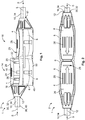
- Fig. 1 shows a perspective side view of the electric wire connector 1.
- the electric wire connector 1 comprises a connector housing 2 with at least one housing cover 4 and a housing base 6.
- the housing base 6 is divided into at least two compartments 8 and the at least one housing cover 4 is adapted to receive at the least one of at least two wires 10 which are supposed to be connected to one another via the electric wire connector 1.
- the connector housing 2 comprises a separate housing cover 4 for each compartment 8, which are each adapted to receive one of the at least two wires 10.
- the wires 10 may extend along a longitudinal axis L and can be inserted through a wire receiving opening 12 into the connector housing 2 in an insertion direction S.
- the housing cover 4 comprises the wire receiving opening 12 and is held linearly movable relative to the housing base 6 from an open position 14 for receiving wire 10 to a closed position 16.
- the housing covers 4 as shown in Figs. 1 to 3 may be separated from one another and independently movable relative to the housing base 6. This has the advantage that during installation one can concentrate on terminating one wire 10 after the other. A user does not have to hold both wires 10 in the connector housing 2, while pushing the housing covers 4 into the closed position 16.
- one housing cover 4 is shown in the closed position 16 and the other housing cover is shown in the open position 14.
- the housing covers 4 are formed identically to one another, therefore increasing the production efficiency.
- the housing cover 4 may comprise a plastic material and preferably be formed by an injection moulding process.
- the housing cover 4 may comprise a guiding slot 18 and locking latches 20 formed on an outer surface 22 facing a side surface of the housing base 6.
- the housing base 6 may comprise complementary formed locking latches 24, which interlock with the locking latches 20 and block further movement of the housing cover 4 relative to the housing base 6.
- the locking latches 20 and the complementary locking latches 24 may lock the housing cover 4 in the closed position 16 preventing any unintentional dismounting.
- the housing cover 4 may be adapted for single use only, meaning that once the housing cover 4 is in a closed position 16 it is locked for good, i.e. cannot be opened without exercising excessive force and/or breaking the housing cover 4. This enables a secure connection, even in harsh environments, where the connector 1 may be subject to a lot of stress such as impact or vibrations.
- the housing cover 4 may comprise a ribbing 28 increasing the grip when handling the connector 1.
- the housing cover 4 may be moved to the closed position 16 by means of tools, such as pliers.
- the ribbing 28 may prevent slipping of the tool.
- the housing cover 4 comprises a marking 29 indicating the point in which the wire 10 is fully inserted.
- the housing cover 4 may be transparent allowing a direct view on the insertion state of the wire 10.
- the electric wire connector 1 may preferably comprise a high impact resistance and may thus be formed comprising a plastic material with such properties, e.g. polyphenylene ether, particularly a modified polyphenylene ether. These materials are often non-transparent, therefore the marking 29 may prevent any installation errors.
- Each housing cover 4 comprises a wire receiving opening 12, which may preferably be formed integrally with the housing cover 4.
- the wire receiving opening 12 may have a circular shape and be adaptable to various wire sizes. Therefore, a single standardized housing cover 4 may be produced for different wire sizes.
- the wire receiving opening 12 may have a maximal cross-section adapted for receiving the largest wire size. Smaller wires may thus still be insertable into the wire receiving opening 12.
- various applications usually require sealed connectors 1 preventing particles, such as dust and humidity, from entering the connector housing 2.
- At least the wire receiving opening 12 may be filled with a sealing material 30, such as a sealing gel 32.
- a sealing material 30 By inserting the wire 10, the sealing material 30 is penetrated leading to the wire receiving opening 12 having an effective cross section adapted to the cross section of the wire 10.
- the wires 10 may preferably be solar wires 34 each having a wire conductor 36 and a wire jacket 38.
- the wire conductor 36 may be formed by individual strands and the jacket 38 may be surrounded by a further insulation 40.
- the solar wire 34 may be doubly isolated.
- FIG. 3 a cut side view of the electric wire connector 1 shown in Figs. 1 and 2 is shown.
- One wire 10, particularly solar wire 34, is installed in one compartment 8, meaning that the wire 10 is inserted into the wire receiving opening 12 of the respective housing cover 4 and the housing cover 4 is moved into the closed position 16.
- the housing cover 4 and the housing base 6 may be filled with the sealing material 30 so that all voids may be filled by the sealing material 30 in the closed position 16 and avoiding that excessive sealing material 30 is pushed out of the connector housing 2, when moving the housing cover 4 from the open position 14 to the closed position 16.
- the other housing cover 4 is shown in the open position 14 before insertion of the wire 10.
- a retention element 42 such as a retention spring 44 may be provided.
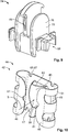
- the retention element 42 is explained in further detail with reference to Fig. 4 showing an explosion view of an exemplary embodiment of a housing cover and Fig.10 showing a schematic perspective view of the retention element 42.
- the retention element 42 may be mounted in the housing cover 4 and comprise a guiding opening 45 arranged coaxially to the wire receiving opening 12.
- the retention element 42 may be a separate part and may be formed by a sheet metal.
- the retention element 42 is a retention spring 44 comprising spring arms 46, which project radially inwardly and may be slightly bent obliquely to the insertion direction S to assume an inclination of 10° to 45° to the insertion direction S.
- the spring arms 46 define hooks cooperating with the outer circumference of the jacket 38, which hooks prevent the wire 10 from being drawn out of the housing after insertion of the wire 10.
- the spring arms 46 are bent towards each other and are distanced from one another by an axial slit 47.
- the center of the axial slit is preferably flush with the center of the guiding opening, so that the wire 10 can be inserted through the slit 47 into the guiding opening 45.
- the flexibility of the spring arms 46 may be further increased by providing cutouts 49 at the bending curves 51 of the spring arms.
- the retention element 42 may be adapted to further absorb any torsional tension of the wire 10, so that the torsional tension is not further transmitted to the contact terminals.
- torsion absorption features 53 are realized by a widening 59 of the axial slit 47 in a direction essentially perpendicular to the insertion direction S. Essentially circumferential recesses 61 of the spring arms 46 bordering the axial slit 47 may form the widening 59.
- the torsion absorption features 53 may prevent rotation of the inserted part of the wire 10 resulting in a stable wire termination.
- the retention element 42 may further be provided with at least one guiding flap 63 extending obliquely from the circumference of the guiding opening 45 towards the axial slit 47.
- the guiding flap 63 may act as a ramp directing the wire 10 after passing the axial slit 47 to the guiding opening 45.
- at least two guiding flaps 63 may be provided, the at least two guiding flaps 63 being arranged diametrically to one another.
- the retention element 42 may preferably be a loose part, which can be fixedly mounted in the housing cover 4.
- the retention element may be provided with locking features 65, such as locking notches 67, which may be pressed into a plastic rib of the housing cover 4.
- the retention element 42 may be further secured by the sealing material 30.
- Fig. 5 shows an explosion view of an exemplary embodiment of a housing base 6.
- the housing base 6 comprises an essentially U-shaped body 48, when looking at it in the insertion direction S.
- the body 48 may preferably be formed as a monolithic piece 50 forming two compartments 8.
- the compartments 8 are preferably symmetrical to one another further facilitating the production process.
- the body 48 may be formed by an injection molding process and may preferably comprise a material with high impact strength.
- a contact sub-assembly 52 may be mounted in the housing base 6.
- the contact sub-assembly 52 is comprised of two contact terminals 53 each adapted to be received in their respective compartments 8 and an electrically conductive member 57, in this case a Cu-strip 55, electrically connecting the two contact terminals 53 to one another.
- the contact terminals 53 may be welded onto the conductive member 57 ensuring a stable and secure connection between the two terminals 53.
- FIG. 6 to 8 Different embodiments of the contact sub-assembly 52 are shown in Figs. 6 to 8 .
- the contact terminals 53 may preferably be insulation displacement contacts (IDCs) 54 comprising a slot 56 bordered by cutting edges 58.
- the slot 56 may preferably be adaptable to the wire size inserted into the slot 56.
- the cutting edges 58 are adapted to cut through the wire jacket 38 and contact the wire conductor 36.
- the IDCs 54 may each be mounted in their respective compartments 8 and be connected to one another by the conductive Cu-strip 55 as depicted in Figs. 5 and 6 .
- the conductive member 57 may further comprise at least one securing feature 60.
- the securing feature 60 may be a diode 62 or a fuse 64 as shown in Figs. 7 and 8 , respectively.
- the securing feature 60 may thus replace a securing feature placed in a different place in the application system.
- a biasing spring 66 may be provided.
- the biasing spring 66 may encompass the IDC 54 and be slidably movable relative to the IDC 54. The movement of the biasing spring 66 may be actuated by movement of the housing cover 4.
- the housing cover 4 may push the biasing spring 66 towards the IDC 54 in the closed position.
- the biasing spring 66 may have an essentially U-shape and be arranged in the housing cover 4 in the open position 14 as seen in Fig. 3 .
- the biasing spring 66 may be attached to the housing cover by adhesive and/or form-fit means.
- a crossbeam 68 of the biasing spring 66 presses the wire 10 in the motion direction and at least in the closed position 16 pushes the wire 10 into the slot 56 and holds it in the slot 56 with a biasing force.
- the biasing spring 66 may comprise arms 70 connected by the crossbeam 68, which slide past the IDC 54 and may be received in a receiving chamber 72 formed in the body 48 of the housing base 6.
- a barrier 74 may be provided, physically separating the two compartments 8.
- the barrier 74 and the housing base 6 may preferably be separate parts, which barrier 74 may be fixedly attached in the housing base 6 after mounting of the contact sub-assembly 52.
- the barrier 74 may comprise a pair of securing ribs 76 arranged opposite to one another, each forming an end wall 78 of the respective compartment 8 in the insertion direction S at least in the open position 14.
- the securing ribs 76 may be arranged to extend into a slot 80 formed between to ribs 82 of the housing cover 4.
- the ribs 82 may be distanced from one another in the insertion direction S, wherein rib 82 that is arranged closer to the respective wire receiving opening 12 in the insertion direction S may form a stop point 84 until which the wire 10 may be inserted into the connector housing 2.
- the slot 80 may preferable be filled with the sealing material, further securing the position of the at least one housing cover 4 and housing base 6 in the insertion direction S and stabilizing the ribs 82. This allows for a greater distance between the ribs 82 of each compartment and may thus further help ensuring that creep and/or clearance requirements are met.
- the barrier 74 may be formed from the same material as the housing base 6. To securely mount the barrier 74, the barrier 74 and the housing base 6 are provided with a clicking mechanism 86. In order to allow an easy passage of the conductive member 57 between both compartments 8, a channel 88 may be provided. The channel 88 may be formed between the barrier 74 and the housing base 6 and encompass the conductive member 57. To further stabilize the mounted barrier 74, sealing material 30 may be provided by filling the channel 88 and the compartments 8.
Landscapes
- Connector Housings Or Holding Contact Members (AREA)
- Details Of Connecting Devices For Male And Female Coupling (AREA)
Priority Applications (2)
| Application Number | Priority Date | Filing Date | Title |
|---|---|---|---|
| EP19174654.4A EP3739688B1 (de) | 2019-05-15 | 2019-05-15 | Elektrodrahtverbinder |
| US16/872,757 US11158960B2 (en) | 2019-05-15 | 2020-05-12 | Electric wire connector |
Applications Claiming Priority (1)
| Application Number | Priority Date | Filing Date | Title |
|---|---|---|---|
| EP19174654.4A EP3739688B1 (de) | 2019-05-15 | 2019-05-15 | Elektrodrahtverbinder |
Publications (2)
| Publication Number | Publication Date |
|---|---|
| EP3739688A1 true EP3739688A1 (de) | 2020-11-18 |
| EP3739688B1 EP3739688B1 (de) | 2022-10-12 |
Family
ID=66554274
Family Applications (1)
| Application Number | Title | Priority Date | Filing Date |
|---|---|---|---|
| EP19174654.4A Active EP3739688B1 (de) | 2019-05-15 | 2019-05-15 | Elektrodrahtverbinder |
Country Status (2)
| Country | Link |
|---|---|
| US (1) | US11158960B2 (de) |
| EP (1) | EP3739688B1 (de) |
Citations (4)
| Publication number | Priority date | Publication date | Assignee | Title |
|---|---|---|---|---|
| EP0631344A2 (de) * | 1993-06-28 | 1994-12-28 | The Whitaker Corporation | Abgedichteter Schneidklemmverbinder |
| US6780044B1 (en) * | 2003-05-05 | 2004-08-24 | Bellsouth Intellectual Property | Splice connector assemblies and methods for using the same |
| US20150053251A1 (en) * | 2012-04-30 | 2015-02-26 | Sma Solar Technology Ag | Cable Clip for Module Electronics |
| EP3324488A1 (de) * | 2016-11-16 | 2018-05-23 | Tyco Electronics AMP Italia S.r.l. | Verbinderanordnung mit andruckleiterelement |
Family Cites Families (5)
| Publication number | Priority date | Publication date | Assignee | Title |
|---|---|---|---|---|
| US8512066B2 (en) | 2009-09-17 | 2013-08-20 | Jowoo-Tech Co. Ltd | Electric wire connector for press connecting electric wires |
| CN102723624B (zh) | 2012-03-30 | 2014-04-16 | 深圳市拓普联科电子有限公司 | 市电电线连接组件及连接方法 |
| KR101422082B1 (ko) | 2013-05-08 | 2014-07-23 | 주식회사 조우테크 | 전선 이음 커넥터용 터미널 및 이를 갖는 전선 이음 커넥터 |
| US9912288B2 (en) * | 2015-06-29 | 2018-03-06 | Te Connectivity Corporation | Cable termination for solar junction box |
| EP3293827B1 (de) * | 2016-09-07 | 2023-10-04 | TE Connectivity Nederland B.V. | Schneidklemmkontaktvorrichtung und verfahren zum elektrischen verbinden eines kabels mit einem mantel und ein leiter mit solch einer vorrichtung |
-
2019
- 2019-05-15 EP EP19174654.4A patent/EP3739688B1/de active Active
-
2020
- 2020-05-12 US US16/872,757 patent/US11158960B2/en active Active
Patent Citations (4)
| Publication number | Priority date | Publication date | Assignee | Title |
|---|---|---|---|---|
| EP0631344A2 (de) * | 1993-06-28 | 1994-12-28 | The Whitaker Corporation | Abgedichteter Schneidklemmverbinder |
| US6780044B1 (en) * | 2003-05-05 | 2004-08-24 | Bellsouth Intellectual Property | Splice connector assemblies and methods for using the same |
| US20150053251A1 (en) * | 2012-04-30 | 2015-02-26 | Sma Solar Technology Ag | Cable Clip for Module Electronics |
| EP3324488A1 (de) * | 2016-11-16 | 2018-05-23 | Tyco Electronics AMP Italia S.r.l. | Verbinderanordnung mit andruckleiterelement |
Also Published As
| Publication number | Publication date |
|---|---|
| EP3739688B1 (de) | 2022-10-12 |
| US11158960B2 (en) | 2021-10-26 |
| US20200366004A1 (en) | 2020-11-19 |
Similar Documents
| Publication | Publication Date | Title |
|---|---|---|
| US8591271B2 (en) | Electrical connection terminal | |
| EP2101376B1 (de) | Verbindungsglied und kabelbaumverbinder | |
| EP0001159B2 (de) | Elektrischer Verbinder | |
| EP1914844B1 (de) | Plug connector with improved cable strain relief | |
| EP0653803B1 (de) | Elektrischer Schneidklemmverbinder mit verbesserter Zugentlastung | |
| KR102248383B1 (ko) | 절연 변위 접점을 포함한 플러그 타입 커넥터 | |
| JPH06507043A (ja) | 差込み可能接続コネクター及び橋絡アダプター | |
| CN107809010B (zh) | 绝缘位移接触装置和将有护套的电缆与导体电连接的方法 | |
| US4722699A (en) | Embedded wire-stripping connector for electrical equipment | |
| US4508410A (en) | Electrical termination system and connector member | |
| US6604956B2 (en) | Self-stripping connecting device for two electric cables | |
| US4749366A (en) | Heavy current electrical termination means | |
| US20160336699A1 (en) | Plug connector device | |
| US4370009A (en) | Slotted plate terminal renewable as spade terminal | |
| JP4632454B2 (ja) | ケーブルコネクタ | |
| EP3739688B1 (de) | Elektrodrahtverbinder | |
| US4793824A (en) | Wedge slot connector | |
| US20220271447A1 (en) | Contact element and conductor terminal for connecting an electrical conductor | |
| US3880489A (en) | Electrical connector | |
| US6120316A (en) | Cable plug connector | |
| KR101098156B1 (ko) | 전선 고정 커넥터 시스템 | |
| CN111758187B (zh) | 具有至少一个过电压保护器的过电压保护装置 | |
| US6299473B1 (en) | Electrical connector, particularly for motor vehicles | |
| CN111602300B (zh) | 用于整体应变消除的具有绝缘移位连接接触件的导线对导线连接件 | |
| EP3324488B1 (de) | Verbinderanordnung mit leiterandrückelement |
Legal Events
| Date | Code | Title | Description |
|---|---|---|---|
| PUAI | Public reference made under article 153(3) epc to a published international application that has entered the european phase |
Free format text: ORIGINAL CODE: 0009012 |
|
| STAA | Information on the status of an ep patent application or granted ep patent |
Free format text: STATUS: THE APPLICATION HAS BEEN PUBLISHED |
|
| AK | Designated contracting states |
Kind code of ref document: A1 Designated state(s): AL AT BE BG CH CY CZ DE DK EE ES FI FR GB GR HR HU IE IS IT LI LT LU LV MC MK MT NL NO PL PT RO RS SE SI SK SM TR |
|
| AX | Request for extension of the european patent |
Extension state: BA ME |
|
| STAA | Information on the status of an ep patent application or granted ep patent |
Free format text: STATUS: REQUEST FOR EXAMINATION WAS MADE |
|
| 17P | Request for examination filed |
Effective date: 20210518 |
|
| RBV | Designated contracting states (corrected) |
Designated state(s): AL AT BE BG CH CY CZ DE DK EE ES FI FR GB GR HR HU IE IS IT LI LT LU LV MC MK MT NL NO PL PT RO RS SE SI SK SM TR |
|
| RAP3 | Party data changed (applicant data changed or rights of an application transferred) |
Owner name: TE CONNECTIVITY NEDERLAND B.V. Owner name: TYCO ELECTRONICS AUSTRIA GMBH |
|
| GRAP | Despatch of communication of intention to grant a patent |
Free format text: ORIGINAL CODE: EPIDOSNIGR1 |
|
| STAA | Information on the status of an ep patent application or granted ep patent |
Free format text: STATUS: GRANT OF PATENT IS INTENDED |
|
| INTG | Intention to grant announced |
Effective date: 20220422 |
|
| GRAS | Grant fee paid |
Free format text: ORIGINAL CODE: EPIDOSNIGR3 |
|
| GRAA | (expected) grant |
Free format text: ORIGINAL CODE: 0009210 |
|
| STAA | Information on the status of an ep patent application or granted ep patent |
Free format text: STATUS: THE PATENT HAS BEEN GRANTED |
|
| AK | Designated contracting states |
Kind code of ref document: B1 Designated state(s): AL AT BE BG CH CY CZ DE DK EE ES FI FR GB GR HR HU IE IS IT LI LT LU LV MC MK MT NL NO PL PT RO RS SE SI SK SM TR |
|
| REG | Reference to a national code |
Ref country code: GB Ref legal event code: FG4D |
|
| REG | Reference to a national code |
Ref country code: CH Ref legal event code: EP |
|
| REG | Reference to a national code |
Ref country code: DE Ref legal event code: R096 Ref document number: 602019020450 Country of ref document: DE |
|
| REG | Reference to a national code |
Ref country code: IE Ref legal event code: FG4D |
|
| REG | Reference to a national code |
Ref country code: AT Ref legal event code: REF Ref document number: 1524729 Country of ref document: AT Kind code of ref document: T Effective date: 20221115 |
|
| REG | Reference to a national code |
Ref country code: LT Ref legal event code: MG9D |
|
| REG | Reference to a national code |
Ref country code: NL Ref legal event code: MP Effective date: 20221012 |
|
| REG | Reference to a national code |
Ref country code: AT Ref legal event code: MK05 Ref document number: 1524729 Country of ref document: AT Kind code of ref document: T Effective date: 20221012 |
|
| PG25 | Lapsed in a contracting state [announced via postgrant information from national office to epo] |
Ref country code: NL Free format text: LAPSE BECAUSE OF FAILURE TO SUBMIT A TRANSLATION OF THE DESCRIPTION OR TO PAY THE FEE WITHIN THE PRESCRIBED TIME-LIMIT Effective date: 20221012 |
|
| PG25 | Lapsed in a contracting state [announced via postgrant information from national office to epo] |
Ref country code: SE Free format text: LAPSE BECAUSE OF FAILURE TO SUBMIT A TRANSLATION OF THE DESCRIPTION OR TO PAY THE FEE WITHIN THE PRESCRIBED TIME-LIMIT Effective date: 20221012 Ref country code: PT Free format text: LAPSE BECAUSE OF FAILURE TO SUBMIT A TRANSLATION OF THE DESCRIPTION OR TO PAY THE FEE WITHIN THE PRESCRIBED TIME-LIMIT Effective date: 20230213 Ref country code: NO Free format text: LAPSE BECAUSE OF FAILURE TO SUBMIT A TRANSLATION OF THE DESCRIPTION OR TO PAY THE FEE WITHIN THE PRESCRIBED TIME-LIMIT Effective date: 20230112 Ref country code: LT Free format text: LAPSE BECAUSE OF FAILURE TO SUBMIT A TRANSLATION OF THE DESCRIPTION OR TO PAY THE FEE WITHIN THE PRESCRIBED TIME-LIMIT Effective date: 20221012 Ref country code: FI Free format text: LAPSE BECAUSE OF FAILURE TO SUBMIT A TRANSLATION OF THE DESCRIPTION OR TO PAY THE FEE WITHIN THE PRESCRIBED TIME-LIMIT Effective date: 20221012 Ref country code: ES Free format text: LAPSE BECAUSE OF FAILURE TO SUBMIT A TRANSLATION OF THE DESCRIPTION OR TO PAY THE FEE WITHIN THE PRESCRIBED TIME-LIMIT Effective date: 20221012 Ref country code: AT Free format text: LAPSE BECAUSE OF FAILURE TO SUBMIT A TRANSLATION OF THE DESCRIPTION OR TO PAY THE FEE WITHIN THE PRESCRIBED TIME-LIMIT Effective date: 20221012 |
|
| PGFP | Annual fee paid to national office [announced via postgrant information from national office to epo] |
Ref country code: FR Payment date: 20230309 Year of fee payment: 5 |
|
| PG25 | Lapsed in a contracting state [announced via postgrant information from national office to epo] |
Ref country code: RS Free format text: LAPSE BECAUSE OF FAILURE TO SUBMIT A TRANSLATION OF THE DESCRIPTION OR TO PAY THE FEE WITHIN THE PRESCRIBED TIME-LIMIT Effective date: 20221012 Ref country code: PL Free format text: LAPSE BECAUSE OF FAILURE TO SUBMIT A TRANSLATION OF THE DESCRIPTION OR TO PAY THE FEE WITHIN THE PRESCRIBED TIME-LIMIT Effective date: 20221012 Ref country code: LV Free format text: LAPSE BECAUSE OF FAILURE TO SUBMIT A TRANSLATION OF THE DESCRIPTION OR TO PAY THE FEE WITHIN THE PRESCRIBED TIME-LIMIT Effective date: 20221012 Ref country code: IS Free format text: LAPSE BECAUSE OF FAILURE TO SUBMIT A TRANSLATION OF THE DESCRIPTION OR TO PAY THE FEE WITHIN THE PRESCRIBED TIME-LIMIT Effective date: 20230212 Ref country code: HR Free format text: LAPSE BECAUSE OF FAILURE TO SUBMIT A TRANSLATION OF THE DESCRIPTION OR TO PAY THE FEE WITHIN THE PRESCRIBED TIME-LIMIT Effective date: 20221012 Ref country code: GR Free format text: LAPSE BECAUSE OF FAILURE TO SUBMIT A TRANSLATION OF THE DESCRIPTION OR TO PAY THE FEE WITHIN THE PRESCRIBED TIME-LIMIT Effective date: 20230113 |
|
| REG | Reference to a national code |
Ref country code: DE Ref legal event code: R097 Ref document number: 602019020450 Country of ref document: DE |
|
| PG25 | Lapsed in a contracting state [announced via postgrant information from national office to epo] |
Ref country code: SM Free format text: LAPSE BECAUSE OF FAILURE TO SUBMIT A TRANSLATION OF THE DESCRIPTION OR TO PAY THE FEE WITHIN THE PRESCRIBED TIME-LIMIT Effective date: 20221012 Ref country code: RO Free format text: LAPSE BECAUSE OF FAILURE TO SUBMIT A TRANSLATION OF THE DESCRIPTION OR TO PAY THE FEE WITHIN THE PRESCRIBED TIME-LIMIT Effective date: 20221012 Ref country code: EE Free format text: LAPSE BECAUSE OF FAILURE TO SUBMIT A TRANSLATION OF THE DESCRIPTION OR TO PAY THE FEE WITHIN THE PRESCRIBED TIME-LIMIT Effective date: 20221012 Ref country code: DK Free format text: LAPSE BECAUSE OF FAILURE TO SUBMIT A TRANSLATION OF THE DESCRIPTION OR TO PAY THE FEE WITHIN THE PRESCRIBED TIME-LIMIT Effective date: 20221012 Ref country code: CZ Free format text: LAPSE BECAUSE OF FAILURE TO SUBMIT A TRANSLATION OF THE DESCRIPTION OR TO PAY THE FEE WITHIN THE PRESCRIBED TIME-LIMIT Effective date: 20221012 |
|
| PGFP | Annual fee paid to national office [announced via postgrant information from national office to epo] |
Ref country code: DE Payment date: 20230321 Year of fee payment: 5 |
|
| PLBE | No opposition filed within time limit |
Free format text: ORIGINAL CODE: 0009261 |
|
| STAA | Information on the status of an ep patent application or granted ep patent |
Free format text: STATUS: NO OPPOSITION FILED WITHIN TIME LIMIT |
|
| PG25 | Lapsed in a contracting state [announced via postgrant information from national office to epo] |
Ref country code: SK Free format text: LAPSE BECAUSE OF FAILURE TO SUBMIT A TRANSLATION OF THE DESCRIPTION OR TO PAY THE FEE WITHIN THE PRESCRIBED TIME-LIMIT Effective date: 20221012 Ref country code: AL Free format text: LAPSE BECAUSE OF FAILURE TO SUBMIT A TRANSLATION OF THE DESCRIPTION OR TO PAY THE FEE WITHIN THE PRESCRIBED TIME-LIMIT Effective date: 20221012 |
|
| 26N | No opposition filed |
Effective date: 20230713 |
|
| REG | Reference to a national code |
Ref country code: DE Ref legal event code: R081 Ref document number: 602019020450 Country of ref document: DE Owner name: TE CONNECTIVITY NEDERLAND B.V., NL Free format text: FORMER OWNERS: TE CONNECTIVITY NEDERLAND B.V., 'S-HERTOGENBOSCH, NL; TYCO ELECTRONICS AUSTRIA GMBH, WIEN, AT Ref country code: DE Ref legal event code: R081 Ref document number: 602019020450 Country of ref document: DE Owner name: TE CONNECTIVITY AUSTRIA GMBH, AT Free format text: FORMER OWNERS: TE CONNECTIVITY NEDERLAND B.V., 'S-HERTOGENBOSCH, NL; TYCO ELECTRONICS AUSTRIA GMBH, WIEN, AT |
|
| PG25 | Lapsed in a contracting state [announced via postgrant information from national office to epo] |
Ref country code: SI Free format text: LAPSE BECAUSE OF FAILURE TO SUBMIT A TRANSLATION OF THE DESCRIPTION OR TO PAY THE FEE WITHIN THE PRESCRIBED TIME-LIMIT Effective date: 20221012 |
|
| REG | Reference to a national code |
Ref country code: CH Ref legal event code: PL |
|
| PG25 | Lapsed in a contracting state [announced via postgrant information from national office to epo] |
Ref country code: MC Free format text: LAPSE BECAUSE OF FAILURE TO SUBMIT A TRANSLATION OF THE DESCRIPTION OR TO PAY THE FEE WITHIN THE PRESCRIBED TIME-LIMIT Effective date: 20221012 |
|
| REG | Reference to a national code |
Ref country code: BE Ref legal event code: MM Effective date: 20230531 |
|
| PG25 | Lapsed in a contracting state [announced via postgrant information from national office to epo] |
Ref country code: MC Free format text: LAPSE BECAUSE OF FAILURE TO SUBMIT A TRANSLATION OF THE DESCRIPTION OR TO PAY THE FEE WITHIN THE PRESCRIBED TIME-LIMIT Effective date: 20221012 Ref country code: LU Free format text: LAPSE BECAUSE OF NON-PAYMENT OF DUE FEES Effective date: 20230515 Ref country code: LI Free format text: LAPSE BECAUSE OF NON-PAYMENT OF DUE FEES Effective date: 20230531 Ref country code: CH Free format text: LAPSE BECAUSE OF NON-PAYMENT OF DUE FEES Effective date: 20230531 |
|
| REG | Reference to a national code |
Ref country code: IE Ref legal event code: MM4A |
|
| PG25 | Lapsed in a contracting state [announced via postgrant information from national office to epo] |
Ref country code: IE Free format text: LAPSE BECAUSE OF NON-PAYMENT OF DUE FEES Effective date: 20230515 |
|
| PG25 | Lapsed in a contracting state [announced via postgrant information from national office to epo] |
Ref country code: IE Free format text: LAPSE BECAUSE OF NON-PAYMENT OF DUE FEES Effective date: 20230515 |
|
| PGFP | Annual fee paid to national office [announced via postgrant information from national office to epo] |
Ref country code: GB Payment date: 20240321 Year of fee payment: 6 |