EP3739609A1 - Nozzle for a circuit breaker, circuit breaker, and method of 3d printing a nozzle for a circuit breaker - Google Patents
Nozzle for a circuit breaker, circuit breaker, and method of 3d printing a nozzle for a circuit breaker Download PDFInfo
- Publication number
- EP3739609A1 EP3739609A1 EP19174447.3A EP19174447A EP3739609A1 EP 3739609 A1 EP3739609 A1 EP 3739609A1 EP 19174447 A EP19174447 A EP 19174447A EP 3739609 A1 EP3739609 A1 EP 3739609A1
- Authority
- EP
- European Patent Office
- Prior art keywords
- nozzle
- circuit breaker
- gas channel
- arcing zone
- contact elements
- Prior art date
- Legal status (The legal status is an assumption and is not a legal conclusion. Google has not performed a legal analysis and makes no representation as to the accuracy of the status listed.)
- Granted
Links
- 238000000034 method Methods 0.000 title claims description 7
- 238000010146 3D printing Methods 0.000 claims abstract description 18
- 239000012530 fluid Substances 0.000 claims description 59
- 239000000463 material Substances 0.000 claims description 22
- 229920001343 polytetrafluoroethylene Polymers 0.000 claims description 9
- 239000004810 polytetrafluoroethylene Substances 0.000 claims description 9
- 229910052582 BN Inorganic materials 0.000 claims description 6
- PZNSFCLAULLKQX-UHFFFAOYSA-N Boron nitride Chemical compound N#B PZNSFCLAULLKQX-UHFFFAOYSA-N 0.000 claims description 6
- 239000004813 Perfluoroalkoxy alkane Substances 0.000 claims description 6
- 229910052982 molybdenum disulfide Inorganic materials 0.000 claims description 6
- 229920011301 perfluoro alkoxyl alkane Polymers 0.000 claims description 6
- 239000004812 Fluorinated ethylene propylene Substances 0.000 claims description 3
- 102100030393 G-patch domain and KOW motifs-containing protein Human genes 0.000 claims description 3
- HQQADJVZYDDRJT-UHFFFAOYSA-N ethene;prop-1-ene Chemical group C=C.CC=C HQQADJVZYDDRJT-UHFFFAOYSA-N 0.000 claims description 3
- CWQXQMHSOZUFJS-UHFFFAOYSA-N molybdenum disulfide Chemical compound S=[Mo]=S CWQXQMHSOZUFJS-UHFFFAOYSA-N 0.000 claims description 3
- 229920009441 perflouroethylene propylene Polymers 0.000 claims description 3
- -1 polytetrafluoroethylene Polymers 0.000 claims description 3
- 238000004519 manufacturing process Methods 0.000 description 10
- 241000722921 Tulipa gesneriana Species 0.000 description 7
- 230000008901 benefit Effects 0.000 description 6
- 229910052751 metal Inorganic materials 0.000 description 5
- 239000002184 metal Substances 0.000 description 5
- 239000011810 insulating material Substances 0.000 description 4
- 230000008878 coupling Effects 0.000 description 3
- 238000010168 coupling process Methods 0.000 description 3
- 238000005859 coupling reaction Methods 0.000 description 3
- 238000013461 design Methods 0.000 description 3
- 238000011084 recovery Methods 0.000 description 3
- 230000015556 catabolic process Effects 0.000 description 2
- 238000003754 machining Methods 0.000 description 2
- 230000002265 prevention Effects 0.000 description 2
- 230000001902 propagating effect Effects 0.000 description 2
- 238000012360 testing method Methods 0.000 description 2
- 238000011144 upstream manufacturing Methods 0.000 description 2
- 230000015572 biosynthetic process Effects 0.000 description 1
- 238000012790 confirmation Methods 0.000 description 1
- 230000001419 dependent effect Effects 0.000 description 1
- 230000005684 electric field Effects 0.000 description 1
- 239000000945 filler Substances 0.000 description 1
- 238000007689 inspection Methods 0.000 description 1
- 239000011159 matrix material Substances 0.000 description 1
- 238000012986 modification Methods 0.000 description 1
- 230000004048 modification Effects 0.000 description 1
- 238000012545 processing Methods 0.000 description 1
- 238000010791 quenching Methods 0.000 description 1
- 230000000171 quenching effect Effects 0.000 description 1
- 238000000926 separation method Methods 0.000 description 1
- 230000007480 spreading Effects 0.000 description 1
- 238000003892 spreading Methods 0.000 description 1
- 230000001052 transient effect Effects 0.000 description 1
Images

Classifications
-
- H—ELECTRICITY
- H01—ELECTRIC ELEMENTS
- H01H—ELECTRIC SWITCHES; RELAYS; SELECTORS; EMERGENCY PROTECTIVE DEVICES
- H01H33/00—High-tension or heavy-current switches with arc-extinguishing or arc-preventing means
- H01H33/70—Switches with separate means for directing, obtaining, or increasing flow of arc-extinguishing fluid
- H01H33/7015—Switches with separate means for directing, obtaining, or increasing flow of arc-extinguishing fluid characterised by flow directing elements associated with contacts
- H01H33/7023—Switches with separate means for directing, obtaining, or increasing flow of arc-extinguishing fluid characterised by flow directing elements associated with contacts characterised by an insulating tubular gas flow enhancing nozzle
-
- H—ELECTRICITY
- H01—ELECTRIC ELEMENTS
- H01H—ELECTRIC SWITCHES; RELAYS; SELECTORS; EMERGENCY PROTECTIVE DEVICES
- H01H11/00—Apparatus or processes specially adapted for the manufacture of electric switches
-
- H—ELECTRICITY
- H01—ELECTRIC ELEMENTS
- H01H—ELECTRIC SWITCHES; RELAYS; SELECTORS; EMERGENCY PROTECTIVE DEVICES
- H01H33/00—High-tension or heavy-current switches with arc-extinguishing or arc-preventing means
- H01H33/70—Switches with separate means for directing, obtaining, or increasing flow of arc-extinguishing fluid
- H01H33/7015—Switches with separate means for directing, obtaining, or increasing flow of arc-extinguishing fluid characterised by flow directing elements associated with contacts
- H01H33/7023—Switches with separate means for directing, obtaining, or increasing flow of arc-extinguishing fluid characterised by flow directing elements associated with contacts characterised by an insulating tubular gas flow enhancing nozzle
- H01H33/703—Switches with separate means for directing, obtaining, or increasing flow of arc-extinguishing fluid characterised by flow directing elements associated with contacts characterised by an insulating tubular gas flow enhancing nozzle having special gas flow directing elements, e.g. grooves, extensions
-
- H—ELECTRICITY
- H01—ELECTRIC ELEMENTS
- H01H—ELECTRIC SWITCHES; RELAYS; SELECTORS; EMERGENCY PROTECTIVE DEVICES
- H01H33/00—High-tension or heavy-current switches with arc-extinguishing or arc-preventing means
- H01H33/70—Switches with separate means for directing, obtaining, or increasing flow of arc-extinguishing fluid
- H01H33/88—Switches with separate means for directing, obtaining, or increasing flow of arc-extinguishing fluid the flow of arc-extinguishing fluid being produced or increased by movement of pistons or other pressure-producing parts
- H01H33/90—Switches with separate means for directing, obtaining, or increasing flow of arc-extinguishing fluid the flow of arc-extinguishing fluid being produced or increased by movement of pistons or other pressure-producing parts this movement being effected by or in conjunction with the contact-operating mechanism
- H01H33/901—Switches with separate means for directing, obtaining, or increasing flow of arc-extinguishing fluid the flow of arc-extinguishing fluid being produced or increased by movement of pistons or other pressure-producing parts this movement being effected by or in conjunction with the contact-operating mechanism making use of the energy of the arc or an auxiliary arc
Definitions
- aspects of the invention relate to a nozzle for a circuit breaker, in particular nozzle for a circuit breaker being manufactured by 3D printing as a single piece. Further aspects relate to circuit breaker including the nozzle. Further aspects relate to a method of 3D printing a nozzle for a circuit breaker.
- Circuit breakers are known. Circuit breakers may have two contact elements which may move relative to each other along a central axis of the circuit breaker. An arc may form when the circuit breaker is opened, that is when the two contact elements are separated from each other. There may be an arcing zone between the two contact elements in which the arc is generated when the circuit breaker is opened or switched. The arc may be extinguished using an extinguishing gas.
- Fig. 1 shows a cross-sectional representation of a part of a circuit-breaker.
- This circuit-breaker has two opposing contact elements 210, 220 which are movable relative to each other along a central axis CA of the circuit-breaker by means of a drive.
- Contact element 210 is a metal contact tulip
- contact element 220 is a metal contact pin.
- An arc area 330 is provided between the two contact elements 210, 220, in which, for example, an arc is formed when the circuit-breaker is opened, in which the two contact elements are separated from each other.
- the circuit-breaker shown in Fig. 1 has a cylindrical auxiliary nozzle 100b which at least partially encloses the contact element 210.
- the inner jacket of the auxiliary nozzle faces the arc area 330.
- the circuit breaker shown has a main nozzle 100a which at least partially encloses the auxiliary nozzle 100b.
- a channel 320 is formed between the auxiliary nozzle 100b and the main nozzle 100a, which connects the arc area 330 with a gas reservoir 310, an upstream reservoir where the gas is temporarily stored with high pressure.
- the gas reservoir 310 is arranged circumferentially outside the auxiliary nozzle 100b.
- auxiliary nozzle which at least partially encloses one of the contact elements
- main nozzle which at least partially encloses the auxiliary nozzle
- a breakdown of insulating gas may initiate in the region around a contact element such as a plug tip.
- the breakdown of insulating gas may lead to a formation of a highly conductive plasma channel or a leader.
- the leader may have a tendency to stick to a nearby wall such as a nozzle surface.
- the leader may travel towards the other contact element such as a tulip under the drive of the electric field generated by the recovery voltage.
- the leader may either bridge over the gap or gas channel and reach the tulip or remain attached to the surface of the nozzle, enter the gap and travel along a surface of the gas channel.
- the leader may travel until it is discharged on a metal part having the same potential as the other contact element or tulip.
- Flashover traces may form when the latter situation, wherein the leader does not bridge the gap but enters the gap, occurs during a breaking operation.
- the flashover traces may form on the nozzle surfaces. Punctures or holes through the nozzle body may also form.
- DE 20 2017 103 766 U1 describes a configuration to guide a plasma channel or a leader from one contact element to the other contact element, along the inner jacket of the main nozzle and the auxiliary nozzle, such that the leader does not enter the gas channel or gap between the main nozzle and the auxiliary nozzle.
- DE 20 2017 103 766 U1 describes a configuration where one of the auxiliary nozzle or the main nozzle has an extension section bridging the channel in a direction parallel to the central axis such that the inner casing or inner jacket or inner surface of the auxiliary nozzle and the inner casing of the main nozzle adjoin one another in a direction parallel to the central axis of the nozzle without interruption or substantially without interruption.
- Substantially without interruption may include a configuration where a narrow gap between the auxiliary nozzle and the main nozzle, for example, a gap of less than 1 mm, is formed such that a leader travelling from one contact element to the other contact element bridges the gap and does not propagate through this gap into the channel. Openings or fluid ducts in the extension region connect the arc region to the gas reservoir and allow gas, such as extinguishing gas, to flow between them.
- auxiliary nozzle and the main nozzle are manufactured independently of each other.
- the openings or fluid ducts on the auxiliary nozzle or the main nozzle are selected such that the openings may be easily machined into the extension section during manufacture.
- the main nozzle and the auxiliary nozzle are then assembled.
- the manufacture of a main nozzle and an auxiliary nozzle, and their assembly involve production tolerances and/or clearance between the auxiliary nozzle and the main nozzle.
- the tolerance and/or clearance between the auxiliary nozzle and the main nozzle plays a role in preventing an arc formed from propagating through the gap into the channel.
- the tolerance and/or clearance must not be so large as to impair the prevention of arc propagation into the channel between the auxiliary nozzle and the main nozzle.
- the tolerance and/or clearance between the auxiliary nozzle and the main nozzle also plays a role in the correct assembly of the circuit breaker. The clearance must not be so small as to cause difficulties during assembly of the auxiliary nozzle and the main nozzle.
- the openings or fluid ducts on the extension sections on the auxiliary nozzle or the main nozzle connecting the arcing zone to the gas channel are selected with considerations of the associated machining and/or manufacturing process.
- the design and/or other processing of the openings such as finishing and/or material considerations may impose some requirements or limitations. That is, manufacturing and/or machining considerations may mean that the openings may not be completely optimized with respect to the performance of the nozzle or circuit breaker such as the gas flow between the gas reservoir and the arcing zone.
- a nozzle for a circuit breaker according to claim 1 a circuit breaker according to claim 14, and a method of 3D printing a nozzle for a circuit breaker according to claim 15 are provided.
- a nozzle for a circuit breaker having at least two contact elements and a gas reservoir
- the nozzle is manufactured by 3D printing as a single piece and configured to surround the at least two contact elements of the circuit breaker at least partially, the nozzle having an arcing zone formed along a central axis of the nozzle; and a gas channel formed within the nozzle and configured to fluidly connect the gas reservoir to the arcing zone, wherein at least one of the contact elements is configured to be movable.
- An advantage is that the issues of manufacturing tolerances and mechanical coupling associated with having two separate nozzles may be eliminated.
- a nozzle made of a single piece obtained with 3D printing manufacturing may replace the combination of two nozzle parts such as an auxiliary nozzle and a main nozzle or an auxiliary nozzle and an insulating nozzle.
- Another advantage may be that flashovers in a channel or gas channel or propagation of a leader into a channel or gas channel may as effectively be avoided or prevented as, or be avoided or prevented better than a combination of two nozzle parts such as an auxiliary nozzle and a main nozzle, or an auxiliary nozzle and an insulating nozzle.
- the arcing zone is configured to be between two or more contact elements of the circuit breaker.
- the arcing zone can be configured to be between the two or more contact elements of the circuit breaker when the nozzle is mounted in the circuit breaker.
- the gas channel is formed in a direction substantially parallel to the arcing zone.
- the nozzle further includes a plurality of fluid ducts formed within the nozzle and configured to fluidly connect the gas channel to the arcing zone.
- fluid ducts or openings may be designed or selected with 3D printing tools so as to optimise the flow of gas, such as extinguishing gas, or optimise for other circuit breaker performance considerations.
- an advantage is that the fluid ducts or openings on the nozzle may be designed or selected with 3D printing tools to optimise the performance of the nozzle such as improved gas flow between the gas channel and the arcing zone.
- 3D printing may provide improved freedom in the design and/or manufacture of the gas channel and/or fluid ducts.
- each fluid duct of the plurality of fluid ducts adjoins the gas channel at one end and adjoins the arcing zone at the other end.
- each fluid duct of the plurality of fluid ducts is formed in a direction substantially perpendicular to the central axis of the nozzle or in a direction at an angle to a radial axis, and wherein the radial axis is perpendicular to the central axis of the nozzle.
- each fluid duct of a plurality of fluid ducts is rotationally asymmetric about a radial axis, and wherein the radial axis is perpendicular to a central axis of the nozzle.
- the plurality of fluid ducts are distributed in a circumferential direction of the nozzle and/or the plurality of fluid ducts are arranged spatially with n-fold rotational symmetry about a central axis of the nozzle.
- the plurality of fluid ducts span an entire gas channel length or a part of a gas channel length.
- the nozzle further includes a continuity of nozzle material configured to direct the propagation of a leader from a first contact element of the circuit breaker to a second contact element of the circuit breaker along at least a first surface of the nozzle, wherein the leader is highly conductive plasma.
- An advantage may be that flashovers in a channel or gas channel or propagation of a leader into a channel or gas channel may be avoided or prevented.
- the first surface continuously abuts the arcing zone and/or the first surface is a surface of a throat of the nozzle.
- the first surface spans the nozzle.
- the nozzle is of a material composition, for example, including PTFE (polytetrafluoroethylene), FEP (fluorinated ethylene propylene), PFA (perfluoroalkoxy alkane), TFM (modified PTFE), MOS2 (molybdenum disulfide), BN (boron nitride), combinations thereof, or any fillings of one of these materials with another one.
- PTFE polytetrafluoroethylene
- FEP fluorinated ethylene propylene
- PFA perfluoroalkoxy alkane
- TFM modified PTFE
- MOS2 molethacrylate
- BN boron nitride
- a circuit breaker having a nozzle.
- Another aspect is directed to a method of 3D printing a nozzle for a circuit breaker, the circuit breaker having at least two contact elements and a gas reservoir, wherein the nozzle is manufactured as a single piece and configured to surround the at least two contact elements of the circuit breaker at least partially, the nozzle having an arcing zone formed along a central axis of the nozzle; and a gas channel formed within the nozzle and configured to fluidly connect the gas reservoir to the arcing zone, wherein at least one of the contact elements is configured to be movable.
- the problem of flashover traces in a channel or gas channel 320 in the nozzle 100 may be avoided.
- the problem of flashover traces may occur in case of an unsuccessful breaking operation.
- the breaking operation may be with a failure of dielectric type.
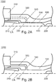
- Figures 2A and 2B show cross-sectional views of a nozzle 100 for a circuit breaker 1000 according to embodiments described herein.
- Figures 2A and 2B are cross-sectional views at two different angles about the central axis CA of the nozzle 100, parallel to the central axis CA of the nozzle 100.
- the nozzle 100 can be configured for a circuit breaker 1000 having at least two contact elements 210, 220. At least one of the contact elements 210, 220 may be configured to be movable.
- the nozzle 100 may be manufactured as a single piece.
- the nozzle 100 may be manufactured by 3D printing.
- the nozzle 100 may be configured to surround the at least two contact elements 210, 220 of the circuit breaker 1000 at least partially.
- An arcing zone may be formed along a central axis CA of the nozzle 100.
- a gas channel 320 may be formed within the nozzle 100.
- the gas channel 320 may be configured to fluidly connect the gas reservoir 310 to the arcing zone 330.
- the nozzle 100 may be made of a single piece.
- the nozzle 100 may be obtained with 3D printing manufacturing.
- a single piece nozzle may replace two or more nozzle parts such as an auxiliary nozzle and a main nozzle.
- a continuity of nozzle material may direct the propagation of a leader 400 from a first contact element 220 to a second contact element 210.
- the leader 400 may be highly conductive plasma.
- the continuity of material may be of an insulating material.
- the leader 400 may travel along a first surface 130 of the continuity of nozzle material.
- the first surface 130 may be continuously abutting the arcing zone 330.
- the first surface 130 may be a surface of a throat of the nozzle 100.
- the first surface 130 may span the nozzle 100.
- the throat of the nozzle 100 may be section or portion of the nozzle 100 with the smallest cross-section or diameter.
- the throat of the nozzle 100 may have a constant cross-section or changing cross-section.
- the throat of the nozzle 100 may be a section or portion of the nozzle 100 surround the arcing zone 330.
- the throat of the nozzle 100 may be an inner surface of the nozzle 100.
- the throat of the nozzle 100 may be a section or portion of the nozzle 100 adjoining the arcing zone 330.
- the leader 400 may travel until it discharges on a contact element 210.
- the contact element 210 may be a tulip contact or pin contact configured for circuit breakers 1000.
- the leader 400 may travel from the first contact element 220 to the second contact element 210, vice versa, or between any two contact elements.
- the contact element 220 may be the other one of the tulip contact or pin contact.
- a nozzle 100 formed or manufactured as a single piece may have improved mechanical stability.
- a single piece nozzle 100 obtained with 3D printing may have improved mechanical stability.
- Fig. 2B shows a cross-sectional view of a nozzle 100, where a plurality of fluid ducts 140 or openings 140 are formed.
- the plurality of fluid ducts 140 may be formed within the nozzle 100.
- the plurality of fluid ducts 140 may be configured to ensure gas flow is not hindered.
- Gas may flow between the gas reservoir 310 and the arcing zone 330 through at least one or more fluid duct 140 or opening 140.
- gas may flow between and/or the plurality of fluid ducts 140 may fluidly connect the gas channel 320 and the arcing zone 330.
- the gas reservoir 310 may be a reservoir or chamber containing gas for extinguishing or quenching an arc.
- the gas in the gas reservoir 310 may be at a pressure higher than the gas elsewhere in the circuit breaker 1000.
- the plurality of fluid ducts 140 or openings 140 may be delimited by parts of the same insulating material that the nozzle 100 is made of.
- the continuity of material may be provided to make it easier for the leader 400 of plasma to discharge on a contact element 210 instead of travelling upstream in a channel or gas channel 320.
- the nozzle 100 is configured for a circuit breaker 1000 that has two opposing contact elements 210, 220 movable relative to one another along a central axis CA of the circuit breaker 1000.
- One or more contact element 210, 220 may be configured to be movable.
- Contact elements may be a metal contact tulip 210 or a metal contact pin 220.
- an arcing zone 330 is provided.
- An arcing zone 330 may be formed between the two or more contact elements 210, 220.
- the arcing zone 330 may be formed along a central axis CA of the nozzle 100.
- the arcing zone 330 may be a zone where an arc is formed when the circuit breaker 1000 is opened or when two contact elements 210; 220 are separated from each other.
- the nozzle 100 may be cylindrical or have any other suitable shape.
- the nozzle 100 may be formed of an insulating material.
- the nozzle 100 may be formed of a material composition suitable for use in circuit breakers. In particular, the material composition may be a result of the 3D printing.
- the material composition of the nozzle 100 may include, without being limited thereto, PTFE (polytetrafluoroethylene), FEP (fluorinated ethylene propylene), PFA (perfluoroalkoxy alkane), TFM (modified PTFE), MOS2 (molybdenum disulfide), BN (boron nitride), or any combination of at least two of these materials. For example, in one combination, one of these materials can be used as a matrix and another one can be used as a filler.
- At least a part of the inner surface of the nozzle 100 may face, adjoin, delimit and/or abut the arcing zone 330.
- a channel or gas channel 320 may be provided.
- the channel 320 may be configured for gas flow. That is, the channel may be a gas channel 320.
- the gas channel 320 may be formed in a direction substantially parallel to the arcing zone 330. Alternatively or in addition, the gas channel 320 may be formed in a direction at an angle to a direction that is parallel to the arcing zone 330.
- the gas channel 320 may be formed as a delimited channel, that is not spanning the entire circumference of the nozzle 100 or the gas channel 320 may be formed spanning substantially the entire circumference of the nozzle 100.
- a plurality of gas channels 320 may be provided instead of or in addition to an annular gas channel 320.
- the gas channel 320 may extend parallel or substantially parallel to the central axis CA of the nozzle 100.
- the gas channel 320 may be configured to fluidly connect the gas reservoir 310 to the arcing zone 330.
- the gas channel 320 may be configured to fluidly connect the gas reservoir 310 to the plurality of fluid ducts 140.
- the plurality of gas channels 320 may resemble a plurality of fluid ducts 140, e.g. in that the plurality of channels 320 connect to the plurality of fluid ducts 140.
- the plurality of fluid ducts 140 may be formed in the nozzle 100.
- the fluid ducts 140 can be openings in the nozzle material.
- the plurality of fluid ducts 140 may be configured to fluidly connect the gas reservoir 310 to the arcing zone 330. Additionally or alternatively, the plurality of fluid ducts 140 may be configured to fluidly connect the gas channel 320 to the arcing zone 330. Additionally or alternatively, the plurality of fluid ducts 140 may be configured to adjoin the gas channel 320 at one end and adjoin the arcing zone 330 at the other end.
- the plurality of fluid ducts 140 may be configured to allow the flow of gas such as extinguishing gas or insulating gas, in particular between the arcing zone 330 and the gas channel 320 and/or gas reservoir 310.
- the plurality of fluid ducts 140 may be configured to optimise the flow of gas, such as extinguishing gas or insulating gas between the arcing zone 330, and the gas channel 320 or gas reservoir 310.
- an extinguishing gas it may be a vacuum, or partial vacuum state.
- the plurality of fluid ducts 140 may adjoin the arcing zone 330 and/or the gas channel 320.
- the plurality of fluid ducts 140 may extend at right angles or substantially at right angles to the central axis CA of the nozzle 100.
- the plurality of fluid ducts 140, or the axis of the plurality of fluid ducts 140 may be at an angle to a radial axis of the nozzle 100.
- the radial axis may be perpendicular to the central axis CA of the nozzle 100.
- At least one fluid duct 140 may be tilted with respect to the radial axis.
- the radial axis of the nozzle 100 is perpendicular to the central axis CA of the nozzle 100.
- the plurality of fluid ducts 140 may be rotationally asymmetric about the radial axis.
- the plurality of fluid ducts 140 may have an oval or a rectangular or a rounded rectangular cross-section or any other suitable cross-section.
- the plurality of fluid ducts 140 may be rotationally symmetric about a radial axis.
- the plurality of fluid ducts 140 may have a circular cross-section, without being limited thereto.
- the plurality of fluid ducts 140 can have any cross-section.
- the fluid ducts 140 may have different geometries or shapes or cross-sections from each other.
- the fluid ducts may have changing cross-section along their length or axis.
- the plurality of fluid ducts 140 may be spatially arranged or distributed in a circumferential direction or rotational direction about the central axis CA of the nozzle 100. Additionally or alternatively, the plurality of fluid ducts 140 may be spatially arranged or distributed in the axial direction or in a direction parallel to the central axis CA of the nozzle 100. Alternatively or in addition, the plurality of fluid ducts 140 may be arranged spatially or distributed with n-fold rotational symmetry about the central axis CA of the nozzle 100. Alternatively or in addition, the plurality of fluid ducts 140 may span the entire gas channel 320 length or a part of the gas channel 320 length.
- a continuity of nozzle material in the nozzle 100 may be configured to guide, direct or conduct the propagation of a leader 400, which may be highly conductive plasma.
- the continuity of nozzle material may be configured to direct a leader 400 from the first contact element 220 of the circuit breaker 1000 to the second contact element 210 of the circuit breaker 1000.
- the continuity of nozzle material may guide a leader 400 along a first surface 130 of the nozzle 100.
- the first surface 130 of the nozzle 100 may continuously adjoin or abut the arcing zone 330.
- the first surface 130 may be a surface of a throat of the nozzle 100.
- the first surface 130 may span the nozzle.
- the first surface 130 may span from a first axial position to a second axial position.
- the first axial position may correspond to the axial position of the first contact element 220 and/or the second axial position may correspond to the axial position of the second contact element 210.
- the axial position may be a position in the direction parallel to the central axis CA of the nozzle 100.
- the continuity of material or the first surface 130 may prevent, hinder or discourage a leader 400 or an arc from travelling, propagating or spreading into the gas channel 320 and/or the plurality of fluid ducts 140.
- the first surface 130 may provide or be formed by a continuity of material or insulating material or insulating surface to guide, direct or conduct a leader 400 to propagate from one contact element 220 to another contact element 210.
- a circuit breaker 1000 may be provided.
- the circuit breaker 1000 may include a nozzle 100.
- the circuit breaker 1000 may include a nozzle 100 according to embodiments described herein.
- a method of 3D printing a nozzle 100 may be provided.
- the method may include 3D printing a nozzle 100 for a circuit breaker 1000.
- the circuit breaker 1000 may have at least two contact elements 210, 220.
- the circuit breaker 1000 may have a gas reservoir 310.
- the nozzle 100 may be manufactured or formed as a single piece.
- the nozzle 100 may be configured to surround the at least two contact elements 210, 220 of the circuit breaker 1000 at least partially.
- the nozzle 100 may comprise an arcing zone 330 formed along a central axis CA of the nozzle 100.
- the nozzle 100 may comprise a gas channel 320 formed within the nozzle 100.
- the nozzle 100 may comprise a gas channel configured to fluidly connect the gas reservoir 310 to the arcing zone 330.
- At least one of the contact elements 210, 220 may be configured to be movable.
- the nozzle 100 can be configured for a circuit breaker 1000 having a rated voltage of > 36 kV.
Landscapes
- Engineering & Computer Science (AREA)
- Manufacturing & Machinery (AREA)
- Circuit Breakers (AREA)
Abstract
Description
- Aspects of the invention relate to a nozzle for a circuit breaker, in particular nozzle for a circuit breaker being manufactured by 3D printing as a single piece. Further aspects relate to circuit breaker including the nozzle. Further aspects relate to a method of 3D printing a nozzle for a circuit breaker.
- Circuit breakers are known. Circuit breakers may have two contact elements which may move relative to each other along a central axis of the circuit breaker. An arc may form when the circuit breaker is opened, that is when the two contact elements are separated from each other. There may be an arcing zone between the two contact elements in which the arc is generated when the circuit breaker is opened or switched. The arc may be extinguished using an extinguishing gas.
-
Fig. 1 shows a cross-sectional representation of a part of a circuit-breaker. This circuit-breaker has twoopposing contact elements Contact element 210 is a metal contact tulip,contact element 220 is a metal contact pin. Anarc area 330 is provided between the twocontact elements Fig. 1 has a cylindricalauxiliary nozzle 100b which at least partially encloses thecontact element 210. The inner jacket of the auxiliary nozzle faces thearc area 330. Furthermore, the circuit breaker shown has amain nozzle 100a which at least partially encloses theauxiliary nozzle 100b. Achannel 320 is formed between theauxiliary nozzle 100b and themain nozzle 100a, which connects thearc area 330 with agas reservoir 310, an upstream reservoir where the gas is temporarily stored with high pressure. Thegas reservoir 310 is arranged circumferentially outside theauxiliary nozzle 100b. After the zero crossing of the current at which the current is meant to be interrupted during the switching operations of such a circuit-breaker, arc restrikes can occur due to the rise of the transient recovery voltage across the breaker terminals. These restrikes can run at least partially throughchannel 320 between theauxiliary nozzle 100b and themain nozzle 100a in an undesirable manner. Such an arc is indicated by thereference number 400 inFig. 1 . It extends from thecontact element 220 along the inner jacket of themain nozzle 100a to the end region of themain nozzle 100a forming a side wall of thechannel 320 and then continues in the channel region at its upper boundary wall inFig. 1 until it is finally deflected in the direction of thecontact element 210. -
DE 20 2017 103 766 U1 describes an auxiliary nozzle which at least partially encloses one of the contact elements, a main nozzle which at least partially encloses the auxiliary nozzle, and a channel between the auxiliary nozzle and the main nozzle. During separation of contact elements when a circuit breaker is opened, a breakdown of insulating gas may initiate in the region around a contact element such as a plug tip. The breakdown of insulating gas may lead to a formation of a highly conductive plasma channel or a leader. The leader may have a tendency to stick to a nearby wall such as a nozzle surface. The leader may travel towards the other contact element such as a tulip under the drive of the electric field generated by the recovery voltage. Once the leader gets in proximity of the gap or gas channel between the main nozzle and the auxiliary nozzle, the leader may either bridge over the gap or gas channel and reach the tulip or remain attached to the surface of the nozzle, enter the gap and travel along a surface of the gas channel. The leader may travel until it is discharged on a metal part having the same potential as the other contact element or tulip. - Flashover traces may form when the latter situation, wherein the leader does not bridge the gap but enters the gap, occurs during a breaking operation. The flashover traces may form on the nozzle surfaces. Punctures or holes through the nozzle body may also form.
- While performing a breaking sequence in a certification test, it is expected that the breaker fails to interrupt the current at the confirmation of minimum arcing time. The IEC standard prescribes that such failed breaking operations must not result in flashover traces. If flashover traces are revealed during an inspection of the breaker, the certification test might be considered to be failed even though the breaker has cleared the IEC sequence.
- Thus, flashover in the gas channel that separates the auxiliary nozzle and main nozzle should be avoided. That is, propagation of a leader along a surface of the gas channel or gap between the auxiliary nozzle and main nozzle should be avoided.
-
DE 20 2017 103 766 U1 describes a configuration to guide a plasma channel or a leader from one contact element to the other contact element, along the inner jacket of the main nozzle and the auxiliary nozzle, such that the leader does not enter the gas channel or gap between the main nozzle and the auxiliary nozzle.DE 20 2017 103 766 U1 describes a configuration where one of the auxiliary nozzle or the main nozzle has an extension section bridging the channel in a direction parallel to the central axis such that the inner casing or inner jacket or inner surface of the auxiliary nozzle and the inner casing of the main nozzle adjoin one another in a direction parallel to the central axis of the nozzle without interruption or substantially without interruption. "Substantially without interruption" may include a configuration where a narrow gap between the auxiliary nozzle and the main nozzle, for example, a gap of less than 1 mm, is formed such that a leader travelling from one contact element to the other contact element bridges the gap and does not propagate through this gap into the channel. Openings or fluid ducts in the extension region connect the arc region to the gas reservoir and allow gas, such as extinguishing gas, to flow between them. -
DE 20 2017 103 766 U1 describes that the auxiliary nozzle and the main nozzle are manufactured independently of each other. The openings or fluid ducts on the auxiliary nozzle or the main nozzle are selected such that the openings may be easily machined into the extension section during manufacture. The main nozzle and the auxiliary nozzle are then assembled. - The manufacture of a main nozzle and an auxiliary nozzle, and their assembly involve production tolerances and/or clearance between the auxiliary nozzle and the main nozzle. The tolerance and/or clearance between the auxiliary nozzle and the main nozzle plays a role in preventing an arc formed from propagating through the gap into the channel. The tolerance and/or clearance must not be so large as to impair the prevention of arc propagation into the channel between the auxiliary nozzle and the main nozzle. The tolerance and/or clearance between the auxiliary nozzle and the main nozzle also plays a role in the correct assembly of the circuit breaker. The clearance must not be so small as to cause difficulties during assembly of the auxiliary nozzle and the main nozzle.
- Furthermore there is also a complication of mechanical coupling between the auxiliary nozzle and the main nozzle. A threaded connection between the auxiliary nozzle and main nozzle would encapsulate air and undermine dielectric recovery.
- Additionally, the openings or fluid ducts on the extension sections on the auxiliary nozzle or the main nozzle connecting the arcing zone to the gas channel are selected with considerations of the associated machining and/or manufacturing process. Thus, the design and/or other processing of the openings such as finishing and/or material considerations may impose some requirements or limitations. That is, manufacturing and/or machining considerations may mean that the openings may not be completely optimized with respect to the performance of the nozzle or circuit breaker such as the gas flow between the gas reservoir and the arcing zone.
- Thus, there is a need to improve the design and/or production method of the nozzles as well as a need to improve the mechanical stability of the nozzles while maintaining the prevention of leader propagation into the gas channel between the auxiliary nozzle and the main nozzle.
- In view of the above, a nozzle for a circuit breaker according to claim 1, a circuit breaker according to claim 14, and a method of 3D printing a nozzle for a circuit breaker according to claim 15 are provided.
- According to an aspect, there is provided a nozzle for a circuit breaker, the circuit breaker having at least two contact elements and a gas reservoir, wherein the nozzle is manufactured by 3D printing as a single piece and configured to surround the at least two contact elements of the circuit breaker at least partially, the nozzle having an arcing zone formed along a central axis of the nozzle; and a gas channel formed within the nozzle and configured to fluidly connect the gas reservoir to the arcing zone, wherein at least one of the contact elements is configured to be movable.
- An advantage is that the issues of manufacturing tolerances and mechanical coupling associated with having two separate nozzles may be eliminated. A nozzle made of a single piece obtained with 3D printing manufacturing may replace the combination of two nozzle parts such as an auxiliary nozzle and a main nozzle or an auxiliary nozzle and an insulating nozzle. Another advantage may be that flashovers in a channel or gas channel or propagation of a leader into a channel or gas channel may as effectively be avoided or prevented as, or be avoided or prevented better than a combination of two nozzle parts such as an auxiliary nozzle and a main nozzle, or an auxiliary nozzle and an insulating nozzle.
- According to embodiments, the arcing zone is configured to be between two or more contact elements of the circuit breaker. Specifically, the arcing zone can be configured to be between the two or more contact elements of the circuit breaker when the nozzle is mounted in the circuit breaker.
- According to embodiments, the gas channel is formed in a direction substantially parallel to the arcing zone.
- According to embodiments, the nozzle further includes a plurality of fluid ducts formed within the nozzle and configured to fluidly connect the gas channel to the arcing zone.
- An advantage may be that fluid ducts or openings may be designed or selected with 3D printing tools so as to optimise the flow of gas, such as extinguishing gas, or optimise for other circuit breaker performance considerations.
- For example, an advantage is that the fluid ducts or openings on the nozzle may be designed or selected with 3D printing tools to optimise the performance of the nozzle such as improved gas flow between the gas channel and the arcing zone.
- Additionally, 3D printing may provide improved freedom in the design and/or manufacture of the gas channel and/or fluid ducts.
- According to embodiments, each fluid duct of the plurality of fluid ducts adjoins the gas channel at one end and adjoins the arcing zone at the other end.
- According to embodiments, each fluid duct of the plurality of fluid ducts is formed in a direction substantially perpendicular to the central axis of the nozzle or in a direction at an angle to a radial axis, and wherein the radial axis is perpendicular to the central axis of the nozzle.
- According to embodiments, each fluid duct of a plurality of fluid ducts is rotationally asymmetric about a radial axis, and wherein the radial axis is perpendicular to a central axis of the nozzle.
- According to embodiments, the plurality of fluid ducts are distributed in a circumferential direction of the nozzle and/or the plurality of fluid ducts are arranged spatially with n-fold rotational symmetry about a central axis of the nozzle.
- According to embodiments, the plurality of fluid ducts span an entire gas channel length or a part of a gas channel length.
- According to embodiments, the nozzle further includes a continuity of nozzle material configured to direct the propagation of a leader from a first contact element of the circuit breaker to a second contact element of the circuit breaker along at least a first surface of the nozzle, wherein the leader is highly conductive plasma.
- An advantage may be that flashovers in a channel or gas channel or propagation of a leader into a channel or gas channel may be avoided or prevented.
- According to embodiments, the first surface continuously abuts the arcing zone and/or the first surface is a surface of a throat of the nozzle.
- According to embodiments, the first surface spans the nozzle.
- According to embodiments, the nozzle is of a material composition, for example, including PTFE (polytetrafluoroethylene), FEP (fluorinated ethylene propylene), PFA (perfluoroalkoxy alkane), TFM (modified PTFE), MOS2 (molybdenum disulfide), BN (boron nitride), combinations thereof, or any fillings of one of these materials with another one.
- According to another aspect, there is provided a circuit breaker having a nozzle.
- Another aspect is directed to a method of 3D printing a nozzle for a circuit breaker, the circuit breaker having at least two contact elements and a gas reservoir, wherein the nozzle is manufactured as a single piece and configured to surround the at least two contact elements of the circuit breaker at least partially, the nozzle having an arcing zone formed along a central axis of the nozzle; and a gas channel formed within the nozzle and configured to fluidly connect the gas reservoir to the arcing zone, wherein at least one of the contact elements is configured to be movable.
- Further advantages, features, aspects and details that can be combined with embodiments described herein are evident from the dependent claims, the description and the drawings.
- The details will be described in the following with reference to the figures, wherein:
-
Fig. 1 is a cross-sectional representation of a part of a circuit-breaker, and -
Figs. 2A and 2B are cross-sectional representations of a nozzle for a circuit breaker at different sections according to embodiments described herein. - Reference will now be made in detail to the various embodiments, one or more examples of which are illustrated in each figure. Each example is provided by way of explanation and is not meant as a limitation. For example, features illustrated or described as part of one embodiment can be used on or in conjunction with any other embodiment to yield yet a further embodiment. It is intended that the present disclosure includes such modifications and variations.
- Within the following description of the drawings, the same reference numbers refer to the same or to similar components. Generally, only the differences with respect to the individual embodiments are described. Unless specified otherwise, the description of a part or aspect in one embodiment applies to a corresponding part or aspect in another embodiment as well.
- The reference numbers used in the figures are merely for illustration. The aspects described herein are not limited to any particular embodiment. Instead, any aspect described herein can be combined with any other aspect(s) or embodiment(s) described herein unless specified otherwise.
- According to aspects or embodiments described herein, the problem of flashover traces in a channel or
gas channel 320 in thenozzle 100 may be avoided. The problem of flashover traces may occur in case of an unsuccessful breaking operation. The breaking operation may be with a failure of dielectric type. -
Figures 2A and 2B show cross-sectional views of anozzle 100 for acircuit breaker 1000 according to embodiments described herein.Figures 2A and 2B are cross-sectional views at two different angles about the central axis CA of thenozzle 100, parallel to the central axis CA of thenozzle 100. - As shown in
Figs. 2A and 2B , thenozzle 100 can be configured for acircuit breaker 1000 having at least twocontact elements contact elements - According to embodiments described herein, the
nozzle 100 may be manufactured as a single piece. Thenozzle 100 may be manufactured by 3D printing. Thenozzle 100 may be configured to surround the at least twocontact elements circuit breaker 1000 at least partially. An arcing zone may be formed along a central axis CA of thenozzle 100. Agas channel 320 may be formed within thenozzle 100. Thegas channel 320 may be configured to fluidly connect thegas reservoir 310 to thearcing zone 330. - According to embodiments described herein, the
nozzle 100 may be made of a single piece. In particular, thenozzle 100 may be obtained with 3D printing manufacturing. A single piece nozzle may replace two or more nozzle parts such as an auxiliary nozzle and a main nozzle. - As shown in
Fig. 2A , asingle piece nozzle 100, a continuity of nozzle material may direct the propagation of aleader 400 from afirst contact element 220 to asecond contact element 210. - The
leader 400 may be highly conductive plasma. The continuity of material may be of an insulating material. - The
leader 400 may travel along afirst surface 130 of the continuity of nozzle material. Thefirst surface 130 may be continuously abutting thearcing zone 330. Thefirst surface 130 may be a surface of a throat of thenozzle 100. Thefirst surface 130 may span thenozzle 100. - The throat of the
nozzle 100 may be section or portion of thenozzle 100 with the smallest cross-section or diameter. The throat of thenozzle 100 may have a constant cross-section or changing cross-section. The throat of thenozzle 100 may be a section or portion of thenozzle 100 surround thearcing zone 330. The throat of thenozzle 100 may be an inner surface of thenozzle 100. The throat of thenozzle 100 may be a section or portion of thenozzle 100 adjoining thearcing zone 330. - The
leader 400 may travel until it discharges on acontact element 210. For example, thecontact element 210 may be a tulip contact or pin contact configured forcircuit breakers 1000. Theleader 400 may travel from thefirst contact element 220 to thesecond contact element 210, vice versa, or between any two contact elements. Further, thecontact element 220 may be the other one of the tulip contact or pin contact. - A
nozzle 100 formed or manufactured as a single piece may have improved mechanical stability. Asingle piece nozzle 100 obtained with 3D printing may have improved mechanical stability. -
Fig. 2B shows a cross-sectional view of anozzle 100, where a plurality offluid ducts 140 oropenings 140 are formed. The plurality offluid ducts 140 may be formed within thenozzle 100. The plurality offluid ducts 140 may be configured to ensure gas flow is not hindered. Gas may flow between thegas reservoir 310 and thearcing zone 330 through at least one or morefluid duct 140 oropening 140. Alternatively or in addition, gas may flow between and/or the plurality offluid ducts 140 may fluidly connect thegas channel 320 and thearcing zone 330. Thegas reservoir 310 may be a reservoir or chamber containing gas for extinguishing or quenching an arc. The gas in thegas reservoir 310 may be at a pressure higher than the gas elsewhere in thecircuit breaker 1000. - The plurality of
fluid ducts 140 oropenings 140 may be delimited by parts of the same insulating material that thenozzle 100 is made of. The continuity of material may be provided to make it easier for theleader 400 of plasma to discharge on acontact element 210 instead of travelling upstream in a channel orgas channel 320. - Possible complications arising from the mechanical coupling between two distinct or separate nozzles with extension sections or insulating bridges between said two distinct or separate nozzles, such as in
DE 20 2017 103 766 U1 , may be avoided by thenozzle 100 of the present disclosure. - According to embodiments described herein, the
nozzle 100 is configured for acircuit breaker 1000 that has two opposingcontact elements circuit breaker 1000. One ormore contact element metal contact tulip 210 or ametal contact pin 220. - According to embodiments described herein, an
arcing zone 330 is provided. Anarcing zone 330 may be formed between the two ormore contact elements arcing zone 330 may be formed along a central axis CA of thenozzle 100. Thearcing zone 330 may be a zone where an arc is formed when thecircuit breaker 1000 is opened or when twocontact elements 210; 220 are separated from each other. - The
nozzle 100 may be cylindrical or have any other suitable shape. Thenozzle 100 may be formed of an insulating material. Thenozzle 100 may be formed of a material composition suitable for use in circuit breakers. In particular, the material composition may be a result of the 3D printing. The material composition of thenozzle 100 may include, without being limited thereto, PTFE (polytetrafluoroethylene), FEP (fluorinated ethylene propylene), PFA (perfluoroalkoxy alkane), TFM (modified PTFE), MOS2 (molybdenum disulfide), BN (boron nitride), or any combination of at least two of these materials. For example, in one combination, one of these materials can be used as a matrix and another one can be used as a filler. - At least a part of the inner surface of the
nozzle 100 may face, adjoin, delimit and/or abut thearcing zone 330. - According to aspects described herein, a channel or
gas channel 320 may be provided. Thechannel 320 may be configured for gas flow. That is, the channel may be agas channel 320. Thegas channel 320 may be formed in a direction substantially parallel to thearcing zone 330. Alternatively or in addition, thegas channel 320 may be formed in a direction at an angle to a direction that is parallel to thearcing zone 330. - Additionally or alternatively, the
gas channel 320 may be formed as a delimited channel, that is not spanning the entire circumference of thenozzle 100 or thegas channel 320 may be formed spanning substantially the entire circumference of thenozzle 100. A plurality ofgas channels 320 may be provided instead of or in addition to anannular gas channel 320. - The
gas channel 320 may extend parallel or substantially parallel to the central axis CA of thenozzle 100. Thegas channel 320 may be configured to fluidly connect thegas reservoir 310 to thearcing zone 330. Thegas channel 320 may be configured to fluidly connect thegas reservoir 310 to the plurality offluid ducts 140. For example, the plurality ofgas channels 320 may resemble a plurality offluid ducts 140, e.g. in that the plurality ofchannels 320 connect to the plurality offluid ducts 140. - In particular, the plurality of
fluid ducts 140 may be formed in thenozzle 100. According to embodiments described herein, thefluid ducts 140 can be openings in the nozzle material. The plurality offluid ducts 140 may be configured to fluidly connect thegas reservoir 310 to thearcing zone 330. Additionally or alternatively, the plurality offluid ducts 140 may be configured to fluidly connect thegas channel 320 to thearcing zone 330. Additionally or alternatively, the plurality offluid ducts 140 may be configured to adjoin thegas channel 320 at one end and adjoin thearcing zone 330 at the other end. - The plurality of
fluid ducts 140 may be configured to allow the flow of gas such as extinguishing gas or insulating gas, in particular between the arcingzone 330 and thegas channel 320 and/orgas reservoir 310. The plurality offluid ducts 140 may be configured to optimise the flow of gas, such as extinguishing gas or insulating gas between the arcingzone 330, and thegas channel 320 orgas reservoir 310. Alternatively, instead of an extinguishing gas, it may be a vacuum, or partial vacuum state. - The plurality of
fluid ducts 140 may adjoin thearcing zone 330 and/or thegas channel 320. The plurality offluid ducts 140 may extend at right angles or substantially at right angles to the central axis CA of thenozzle 100. Alternatively or in addition, the plurality offluid ducts 140, or the axis of the plurality offluid ducts 140 may be at an angle to a radial axis of thenozzle 100. The radial axis may be perpendicular to the central axis CA of thenozzle 100. - That is, at least one
fluid duct 140 may be tilted with respect to the radial axis. The radial axis of thenozzle 100 is perpendicular to the central axis CA of thenozzle 100. - The plurality of
fluid ducts 140 may be rotationally asymmetric about the radial axis. For example, the plurality offluid ducts 140 may have an oval or a rectangular or a rounded rectangular cross-section or any other suitable cross-section. Alternatively, the plurality offluid ducts 140 may be rotationally symmetric about a radial axis. For example, the plurality offluid ducts 140 may have a circular cross-section, without being limited thereto. In particular, the plurality offluid ducts 140 can have any cross-section. Further, thefluid ducts 140 may have different geometries or shapes or cross-sections from each other. In addition or alternatively, the fluid ducts may have changing cross-section along their length or axis. - The plurality of
fluid ducts 140 may be spatially arranged or distributed in a circumferential direction or rotational direction about the central axis CA of thenozzle 100. Additionally or alternatively, the plurality offluid ducts 140 may be spatially arranged or distributed in the axial direction or in a direction parallel to the central axis CA of thenozzle 100. Alternatively or in addition, the plurality offluid ducts 140 may be arranged spatially or distributed with n-fold rotational symmetry about the central axis CA of thenozzle 100. Alternatively or in addition, the plurality offluid ducts 140 may span theentire gas channel 320 length or a part of thegas channel 320 length. - A continuity of nozzle material in the
nozzle 100 may be configured to guide, direct or conduct the propagation of aleader 400, which may be highly conductive plasma. The continuity of nozzle material may be configured to direct aleader 400 from thefirst contact element 220 of thecircuit breaker 1000 to thesecond contact element 210 of thecircuit breaker 1000. - In particular, the continuity of nozzle material may guide a
leader 400 along afirst surface 130 of thenozzle 100. Thefirst surface 130 of thenozzle 100 may continuously adjoin or abut thearcing zone 330. Alternatively or in addition, thefirst surface 130 may be a surface of a throat of thenozzle 100. Alternatively or in addition, thefirst surface 130 may span the nozzle. Alternatively or in addition, thefirst surface 130 may span from a first axial position to a second axial position. The first axial position may correspond to the axial position of thefirst contact element 220 and/or the second axial position may correspond to the axial position of thesecond contact element 210. The axial position may be a position in the direction parallel to the central axis CA of thenozzle 100. - The continuity of material or the
first surface 130 may prevent, hinder or discourage aleader 400 or an arc from travelling, propagating or spreading into thegas channel 320 and/or the plurality offluid ducts 140. In particular, thefirst surface 130 may provide or be formed by a continuity of material or insulating material or insulating surface to guide, direct or conduct aleader 400 to propagate from onecontact element 220 to anothercontact element 210. - According to aspects described herein, a
circuit breaker 1000 may be provided. Thecircuit breaker 1000 may include anozzle 100. Thecircuit breaker 1000 may include anozzle 100 according to embodiments described herein. - According to embodiments described herein, a method of 3D printing a
nozzle 100 may be provided. The method may include 3D printing anozzle 100 for acircuit breaker 1000. Thecircuit breaker 1000 may have at least twocontact elements circuit breaker 1000 may have agas reservoir 310. Thenozzle 100 may be manufactured or formed as a single piece. Thenozzle 100 may be configured to surround the at least twocontact elements circuit breaker 1000 at least partially. Thenozzle 100 may comprise anarcing zone 330 formed along a central axis CA of thenozzle 100. Thenozzle 100 may comprise agas channel 320 formed within thenozzle 100. Thenozzle 100 may comprise a gas channel configured to fluidly connect thegas reservoir 310 to thearcing zone 330. At least one of thecontact elements - According to embodiments described herein, the
nozzle 100 can be configured for acircuit breaker 1000 having a rated voltage of > 36 kV.
Claims (15)
- Nozzle (100) for a circuit breaker, the circuit breaker having at least two contact elements (210; 220) and a gas reservoir (310), wherein the nozzle is manufactured by 3D printing as a single piece and configured to surround the at least two contact elements (210; 220) of the circuit breaker at least partially, the nozzle (100) comprising:an arcing zone (330) formed along a central axis (CA) of the nozzle (100); anda gas channel (320) formed within the nozzle (100) and configured to fluidly connect the gas reservoir (310) to the arcing zone (330),wherein at least one of the contact elements (210; 220) is configured to be movable.
- Nozzle (100) of claim 1, wherein the arcing zone (330) is configured to be between the two or more contact elements (210; 220) of the circuit breaker.
- Nozzle (100) of claim 1 or 2, wherein the gas channel (320) is formed in a direction substantially parallel to the arcing zone (330).
- Nozzle (100) of any of the preceding claims, further comprising a plurality of fluid ducts (140) formed within the nozzle (100) and configured to fluidly connect the gas channel (320) to the arcing zone (330).
- Nozzle (100) of claim 4, wherein each fluid duct of the plurality of fluid ducts (140) adjoins the gas channel (320) at one end and adjoins the arcing zone (330) at the other end.
- Nozzle (100) of claim 4 or 5, wherein each fluid duct of the plurality of fluid ducts (140) is formed in a direction substantially perpendicular to the central axis (CA) of the nozzle (100) or in a direction at an angle to a radial axis (RA), and wherein the radial axis (RA) is perpendicular to the central axis (CA) of the nozzle (100).
- Nozzle (100) of any claims 4 to 6, wherein each fluid duct of the plurality of fluid ducts (140) is rotationally asymmetric about a radial axis (RA), and wherein the radial axis (RA) is perpendicular to the central axis (CA) of the nozzle (100).
- Nozzle (100) of any of claims 4 to 7, wherein the plurality of fluid ducts (140) are distributed in a circumferential direction (CD) of the nozzle (100) and/or the plurality of fluid ducts (140) are arranged spatially with n-fold rotational symmetry about the central axis (CA) of the nozzle (100).
- Nozzle (100) of any of claims 4 to 8, wherein the plurality of fluid ducts (140) span the entire gas channel (320) length or a part of the gas channel (320) length.
- Nozzle (100) of any of the preceding claims, further comprising a continuity of nozzle material configured to direct the propagation of a leader (400) from a first contact element (210) of the circuit breaker to a second contact element (220) of the circuit breaker along at least a first surface (130) of the nozzle (100), wherein the leader (400) is highly conductive plasma.
- Nozzle (100) of claim 10, wherein the first surface (130) continuously abuts the arcing zone (330) and/or the first surface (130) is a surface of a throat of the nozzle (100).
- Nozzle (100) of claim 10 or 11 wherein the first surface (130) spans the nozzle (100).
- Nozzle (100) of any of the preceding claims, wherein the nozzle (100) is of a material composition including for example PTFE, (polytetrafluoroethylene), FEP (fluorinated ethylene propylene), PFA (perfluoroalkoxy alkane), TFM (modified PTFE), MOS2 (molybdenum disulfide), BN (boron nitride), combinations thereof, or any fillings of one of these materials with another one.
- Circuit breaker (1000) comprising a nozzle (100) of any one of the preceding claims.
- Method of 3D printing a nozzle (100) for a circuit breaker, the circuit breaker having at least two contact elements (210; 220) and a gas reservoir (310), wherein the nozzle is manufactured as a single piece and configured to surround the at least two contact elements (210; 220) of the circuit breaker at least partially, the nozzle (100) comprising:an arcing zone (330) formed along a central axis (CA) of the nozzle (100); anda gas channel (320) formed within the nozzle (100) and configured to fluidly connect the gas reservoir (310) to the arcing zone (330),wherein at least one of the contact elements (210; 220) is configured to be movable.
Priority Applications (3)
| Application Number | Priority Date | Filing Date | Title |
|---|---|---|---|
| EP19174447.3A EP3739609B1 (en) | 2019-05-14 | 2019-05-14 | Nozzle for a circuit breaker, circuit breaker, and method of 3d printing a nozzle for a circuit breaker |
| PCT/EP2020/062838 WO2020229338A1 (en) | 2019-05-14 | 2020-05-08 | Nozzle for a circuit breaker, circuit breaker, and method of 3d printing a nozzle for a circuit breaker |
| JP2021568134A JP2022532384A (en) | 2019-05-14 | 2020-05-08 | How to 3D print nozzles for circuit breakers, circuit breakers, and nozzles for circuit breakers |
Applications Claiming Priority (1)
| Application Number | Priority Date | Filing Date | Title |
|---|---|---|---|
| EP19174447.3A EP3739609B1 (en) | 2019-05-14 | 2019-05-14 | Nozzle for a circuit breaker, circuit breaker, and method of 3d printing a nozzle for a circuit breaker |
Publications (2)
| Publication Number | Publication Date |
|---|---|
| EP3739609A1 true EP3739609A1 (en) | 2020-11-18 |
| EP3739609B1 EP3739609B1 (en) | 2024-09-18 |
Family
ID=66542158
Family Applications (1)
| Application Number | Title | Priority Date | Filing Date |
|---|---|---|---|
| EP19174447.3A Active EP3739609B1 (en) | 2019-05-14 | 2019-05-14 | Nozzle for a circuit breaker, circuit breaker, and method of 3d printing a nozzle for a circuit breaker |
Country Status (3)
| Country | Link |
|---|---|
| EP (1) | EP3739609B1 (en) |
| JP (1) | JP2022532384A (en) |
| WO (1) | WO2020229338A1 (en) |
Citations (4)
| Publication number | Priority date | Publication date | Assignee | Title |
|---|---|---|---|---|
| EP2827353A1 (en) * | 2013-07-18 | 2015-01-21 | ABB Technology AG | Electrical switching device |
| JP2016219317A (en) * | 2015-05-22 | 2016-12-22 | 株式会社東芝 | Gas Circuit Breaker |
| DE202017103766U1 (en) | 2017-06-23 | 2017-07-18 | Abb Schweiz Ag | High-voltage circuit breakers |
| WO2018001798A1 (en) * | 2016-06-29 | 2018-01-04 | General Electric Technology Gmbh | An electric arc-blast nozzle and a circuit breaker including such a nozzle |
Family Cites Families (4)
| Publication number | Priority date | Publication date | Assignee | Title |
|---|---|---|---|---|
| JPH0869735A (en) * | 1994-08-31 | 1996-03-12 | Kansai Electric Power Co Inc:The | High voltage dc switch |
| KR101809385B1 (en) * | 2013-07-19 | 2017-12-14 | 가부시키가이샤 히타치세이사쿠쇼 | Gas circuit breaker |
| WO2017159433A1 (en) * | 2016-03-14 | 2017-09-21 | 三菱電機株式会社 | Arc-extinguishing insulation material molding and gas circuit breaker provided with same |
| JP2018116852A (en) * | 2017-01-19 | 2018-07-26 | 株式会社日立製作所 | Gas-blast circuit breaker |
-
2019
- 2019-05-14 EP EP19174447.3A patent/EP3739609B1/en active Active
-
2020
- 2020-05-08 WO PCT/EP2020/062838 patent/WO2020229338A1/en active Application Filing
- 2020-05-08 JP JP2021568134A patent/JP2022532384A/en active Pending
Patent Citations (4)
| Publication number | Priority date | Publication date | Assignee | Title |
|---|---|---|---|---|
| EP2827353A1 (en) * | 2013-07-18 | 2015-01-21 | ABB Technology AG | Electrical switching device |
| JP2016219317A (en) * | 2015-05-22 | 2016-12-22 | 株式会社東芝 | Gas Circuit Breaker |
| WO2018001798A1 (en) * | 2016-06-29 | 2018-01-04 | General Electric Technology Gmbh | An electric arc-blast nozzle and a circuit breaker including such a nozzle |
| DE202017103766U1 (en) | 2017-06-23 | 2017-07-18 | Abb Schweiz Ag | High-voltage circuit breakers |
Also Published As
| Publication number | Publication date |
|---|---|
| JP2022532384A (en) | 2022-07-14 |
| EP3739609B1 (en) | 2024-09-18 |
| WO2020229338A1 (en) | 2020-11-19 |
| WO2020229338A9 (en) | 2021-08-12 |
Similar Documents
| Publication | Publication Date | Title |
|---|---|---|
| CN109564832B (en) | Gas-insulated low-voltage or medium-voltage load-break switch | |
| US8502101B2 (en) | Circuit breaker | |
| EP2346061B1 (en) | Electrode structure for vacuum circuit breaker | |
| TW201521066A (en) | Gas circuit breaker | |
| EP3739609B1 (en) | Nozzle for a circuit breaker, circuit breaker, and method of 3d printing a nozzle for a circuit breaker | |
| EP3926654B1 (en) | Circuit breaker with field deflection element | |
| EP3422381A1 (en) | Gas-insulated load break switch and switchgear comprising a gas-insulated load break switch | |
| EP3488458B1 (en) | Gas-insulated high-voltage switching device with improved main nozzle | |
| JP2023119315A (en) | vacuum valve | |
| CN110402475B (en) | High-voltage circuit breaker with improved robustness | |
| EP4246548A1 (en) | Interrupter unit for gas-insulated high or medium voltage device and gas-insulated high or medium voltage device | |
| EP3132461B1 (en) | High voltage switching device with auxiliary nozzle | |
| WO2023135639A1 (en) | Gas circuit breaker | |
| JP5422472B2 (en) | Gas circuit breaker | |
| WO2017034899A1 (en) | Vacuum switching apparatus and electrical contact therefor | |
| EP4053873A1 (en) | Insulating nozzle for circuit breaker with improved inner configuration | |
| JP4684373B1 (en) | Gas circuit breaker | |
| US2134506A (en) | Electric circuit interrupter | |
| WO2020084984A1 (en) | Gas circuit breaker | |
| KR200489975Y1 (en) | Fixed Structre of High Speed Earthing Switch | |
| KR20210116140A (en) | Gas Insulation Switchgear | |
| KR20190118884A (en) | Switching mechanism for gas inulated switchgear | |
| JPH1186697A (en) | Dc puffer type gas-blast circuit-breaker | |
| CN110556262A (en) | High-voltage circuit breaker | |
| JP2017034921A (en) | Opening/closing device |
Legal Events
| Date | Code | Title | Description |
|---|---|---|---|
| PUAI | Public reference made under article 153(3) epc to a published international application that has entered the european phase |
Free format text: ORIGINAL CODE: 0009012 |
|
| STAA | Information on the status of an ep patent application or granted ep patent |
Free format text: STATUS: THE APPLICATION HAS BEEN PUBLISHED |
|
| AK | Designated contracting states |
Kind code of ref document: A1 Designated state(s): AL AT BE BG CH CY CZ DE DK EE ES FI FR GB GR HR HU IE IS IT LI LT LU LV MC MK MT NL NO PL PT RO RS SE SI SK SM TR |
|
| AX | Request for extension of the european patent |
Extension state: BA ME |
|
| STAA | Information on the status of an ep patent application or granted ep patent |
Free format text: STATUS: REQUEST FOR EXAMINATION WAS MADE |
|
| 17P | Request for examination filed |
Effective date: 20210517 |
|
| RBV | Designated contracting states (corrected) |
Designated state(s): AL AT BE BG CH CY CZ DE DK EE ES FI FR GB GR HR HU IE IS IT LI LT LU LV MC MK MT NL NO PL PT RO RS SE SI SK SM TR |
|
| RAP3 | Party data changed (applicant data changed or rights of an application transferred) |
Owner name: HITACHI ENERGY SWITZERLAND AG |
|
| STAA | Information on the status of an ep patent application or granted ep patent |
Free format text: STATUS: EXAMINATION IS IN PROGRESS |
|
| 17Q | First examination report despatched |
Effective date: 20220801 |
|
| P01 | Opt-out of the competence of the unified patent court (upc) registered |
Effective date: 20230527 |
|
| RAP1 | Party data changed (applicant data changed or rights of an application transferred) |
Owner name: HITACHI ENERGY LTD |
|
| GRAP | Despatch of communication of intention to grant a patent |
Free format text: ORIGINAL CODE: EPIDOSNIGR1 |
|
| STAA | Information on the status of an ep patent application or granted ep patent |
Free format text: STATUS: GRANT OF PATENT IS INTENDED |
|
| RIC1 | Information provided on ipc code assigned before grant |
Ipc: H01H 33/90 20060101ALN20240328BHEP Ipc: H01H 33/70 20060101ALI20240328BHEP Ipc: H01H 11/00 20060101AFI20240328BHEP |
|
| INTG | Intention to grant announced |
Effective date: 20240423 |
|
| GRAS | Grant fee paid |
Free format text: ORIGINAL CODE: EPIDOSNIGR3 |
|
| GRAA | (expected) grant |
Free format text: ORIGINAL CODE: 0009210 |
|
| STAA | Information on the status of an ep patent application or granted ep patent |
Free format text: STATUS: THE PATENT HAS BEEN GRANTED |
|
| AK | Designated contracting states |
Kind code of ref document: B1 Designated state(s): AL AT BE BG CH CY CZ DE DK EE ES FI FR GB GR HR HU IE IS IT LI LT LU LV MC MK MT NL NO PL PT RO RS SE SI SK SM TR |
|
| REG | Reference to a national code |
Ref country code: GB Ref legal event code: FG4D |
|
| RIN1 | Information on inventor provided before grant (corrected) |
Inventor name: KARRER, RETO Inventor name: DHOTRE, MAHESH Inventor name: COSTYSON, JOHAN KARL FILIP Inventor name: DOIRON, CHARLES Inventor name: GOTTI, MANUEL Inventor name: HERRMANN, LORENZ Inventor name: GALLETTI, BERNARDO |