EP2827353A1 - Electrical switching device - Google Patents
Electrical switching device Download PDFInfo
- Publication number
- EP2827353A1 EP2827353A1 EP13177036.4A EP13177036A EP2827353A1 EP 2827353 A1 EP2827353 A1 EP 2827353A1 EP 13177036 A EP13177036 A EP 13177036A EP 2827353 A1 EP2827353 A1 EP 2827353A1
- Authority
- EP
- European Patent Office
- Prior art keywords
- insulating element
- channel
- contact
- switching device
- electrical switching
- Prior art date
- Legal status (The legal status is an assumption and is not a legal conclusion. Google has not performed a legal analysis and makes no representation as to the accuracy of the status listed.)
- Withdrawn
Links
Images
Classifications
-
- H—ELECTRICITY
- H01—ELECTRIC ELEMENTS
- H01H—ELECTRIC SWITCHES; RELAYS; SELECTORS; EMERGENCY PROTECTIVE DEVICES
- H01H33/00—High-tension or heavy-current switches with arc-extinguishing or arc-preventing means
- H01H33/70—Switches with separate means for directing, obtaining, or increasing flow of arc-extinguishing fluid
- H01H33/7015—Switches with separate means for directing, obtaining, or increasing flow of arc-extinguishing fluid characterised by flow directing elements associated with contacts
- H01H33/7023—Switches with separate means for directing, obtaining, or increasing flow of arc-extinguishing fluid characterised by flow directing elements associated with contacts characterised by an insulating tubular gas flow enhancing nozzle
- H01H33/703—Switches with separate means for directing, obtaining, or increasing flow of arc-extinguishing fluid characterised by flow directing elements associated with contacts characterised by an insulating tubular gas flow enhancing nozzle having special gas flow directing elements, e.g. grooves, extensions
-
- H—ELECTRICITY
- H01—ELECTRIC ELEMENTS
- H01H—ELECTRIC SWITCHES; RELAYS; SELECTORS; EMERGENCY PROTECTIVE DEVICES
- H01H1/00—Contacts
- H01H1/12—Contacts characterised by the manner in which co-operating contacts engage
- H01H1/36—Contacts characterised by the manner in which co-operating contacts engage by sliding
- H01H1/38—Plug-and-socket contacts
- H01H1/385—Contact arrangements for high voltage gas blast circuit breakers
-
- H—ELECTRICITY
- H01—ELECTRIC ELEMENTS
- H01H—ELECTRIC SWITCHES; RELAYS; SELECTORS; EMERGENCY PROTECTIVE DEVICES
- H01H33/00—High-tension or heavy-current switches with arc-extinguishing or arc-preventing means
- H01H33/70—Switches with separate means for directing, obtaining, or increasing flow of arc-extinguishing fluid
- H01H33/88—Switches with separate means for directing, obtaining, or increasing flow of arc-extinguishing fluid the flow of arc-extinguishing fluid being produced or increased by movement of pistons or other pressure-producing parts
- H01H33/90—Switches with separate means for directing, obtaining, or increasing flow of arc-extinguishing fluid the flow of arc-extinguishing fluid being produced or increased by movement of pistons or other pressure-producing parts this movement being effected by or in conjunction with the contact-operating mechanism
- H01H33/91—Switches with separate means for directing, obtaining, or increasing flow of arc-extinguishing fluid the flow of arc-extinguishing fluid being produced or increased by movement of pistons or other pressure-producing parts this movement being effected by or in conjunction with the contact-operating mechanism the arc-extinguishing fluid being air or gas
Definitions
- the invention relates to the field of medium and high voltage switching technologies and concerns an electrical switching device and a method for operating the electrical switching device according to the independent claims, particularly for use as an earthing device, a fast-acting earthing device, a circuit breaker, a generator circuit breaker, a switch disconnector, a combined disconnector and earthing switch, or a load break switch in power transmission and distribution systems.
- Electrical switching devices are well known in the field of medium and high voltage switching applications. They are e.g. used for interrupting a current when an electrical fault occurs. As an example, circuit breakers have the task of opening contacts and keeping them far apart from one another in order to avoid a current flow, even in case of high electrical potential originating from the electrical fault itself.
- medium voltage refers to voltages from 1 kV to 72.5 kV and the term high voltage refers to voltages higher than 72.5 kV.
- the electrical switching devices may have to be able to carry high nominal currents of 4000 A to 6300 A and to switch very high short circuit currents of 40 kA to 80 kA at very high voltages of 110 kV to 1200 kV.
- the electrical switching devices of today require many so-called nominal contact fingers for the nominal current.
- the current When disconnecting (opening) a nominal or short circuit current within the electrical switching devices, the current commutates from the nominal contacts of the electrical switching device to its arcing contacts.
- the arcing contacts are connected. They normally comprise as one arcing contact arcing contact fingers arranged around the longitudinal axis of the electrical switching device in a so-called arcing finger cage or tulip and, as a mating arcing contact, a rod which is driven into the finger cage.
- the electrical switching devices In order to interrupt the current, the electrical switching devices contain a dielectrically inert fluid used as an insulating medium and to quench the electric arc. Quenching the electric arc means extracting as much energy as possible from it. Consequently, a part of the fluid located in the region where the electric arc is generated, called arcing volume, is considerably heated up (to around 20'000 °C to 30'000 °C) in a very short time period. Because of its volume expansion this part of the fluid builds up a pressure and is ejected from the arcing volume into a so-called expansion volume. In this way the electric arc is blown off around the instant when the current is zero.
- an additional volume called heating volume or compression volume is used to heat up or pressurize gas located therein. This pressurized gas is then blown into the arcing volume in order to extinguish the electric arc.
- the patent EP 0 753 873 describes a high voltage power switch with an insulating element having openings/channels connecting the heating volume mentioned above with the arcing volume. These extra channels open up directly into the arcing volume where the inner surface of both nozzles is substantially aligned with the breaker axis.
- an electrical switching device with a contact arrangement having a longitudinal axis comprises a first contact and a second contact.
- the two contacts are arranged coaxially with respect to one another and interact electrically and mechanically with one another for closing and opening the contact arrangement by moving at least one of the contacts along the longitudinal axis.
- the electrical switching device further comprises an insulating element enclosing at least partly the first contact and a first auxiliary insulating element enclosing at least partly the second contact.
- An arcing volume is defined between the first contact and the second contact and delimited by inner walls of the insulating element and of the first auxiliary insulating element.
- the arcing volume is connected to a pressurized gas volume via a first channel, in such a way that an insulating fluid can travel between the two volumes through the first channel.
- the first channel comprises a first section opening out in the arcing volume and of a second section opening out in the pressurized gas volume.
- the first section is delimited by a front face of the first auxiliary insulating element and at least by a front face of the insulating element.
- At least a first bypass channel is provided in the first auxiliary insulating element.
- the first bypass channel opens up on one side in the second section of the first channel and it opens up on the other side in a first transitional area between the front face of the first auxiliary insulating element and an inner wall of the first auxiliary insulating element.
- the objective is solved by a method for operating the electrical switching device according to the invention.
- an insulating fluid located in the electrical switching device is guided from a pressurized gas volume into an arcing volume in order to cool down or extinguish an electric arc generated during a switching operation of the first and the second contact in such a way that a fluid stream is split into a first stream travelling through the first channel and a second stream travelling through a plurality of first bypass channels arranged in an annular manner with respect to the longitudinal axis in the first auxiliary insulating element, and the first and the second stream are reunited immediately at a common opening of the first channel and of the first bypass channel into the arcing volume.
- first and the second contact are arcing contacts forming a conductive path when the electrical switching device changes its switching state.
- a third and a fourth contact are provided for carrying a nominal current when the electrical switching device is in a closed state.
- a plurality of first bypass channels are distributed substantially in an annular manner with respect to the longitudinal axis along the first auxiliary insulating element at predefined mutual distances.
- a second auxiliary insulation element is attached to the insulating element and is arranged in such a way that at least a second bypass channel is formed between the second auxiliary insulating element and the insulating element.
- the second bypass channel opens up on one side in the second section of the first channel and opens up on the other side in a second transitional area between the first section of the first channel and an inner wall of the insulating element.
- the electrical switching device comprises an insulating fluid in its interior.
- the fluid is selected from the group consisting of: SF 6 gas, CO 2 gas, SF 6 gas with an admixture gas, CO 2 gas with an admixture gas, any other switching gas or gas mixture, a liquid.
- the electrical switching device according to the invention is used as an earthing device, a fast-acting earthing device, a circuit breaker, a generator circuit breaker, a switch disconnector, a combined disconnector and earthing switch, or a load break switch.
- fluid comprises all liquid and gaseous materials (e.g. SF 6 gas, CO 2 gas or gas mixtures comprising SF 6 and/or CO 2 ) having dielectric capabilities known to be required for a circuit breaker.
- gaseous materials e.g. SF 6 gas, CO 2 gas or gas mixtures comprising SF 6 and/or CO 2
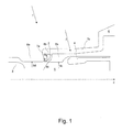
- Fig. 1 shows a longitudinal sectional view of a part of an embodiment of a circuit breaker 1 in an opened configuration.
- the device 1 is rotationally symmetric about a longitudinal axis z.
- Only the elements of the circuit breaker 1 which are related to the present invention will be described in the following, other elements, e.g. nominal contacts, enclosure, etc, are not shown in the figures for clarity reasons. These elements are not immediately relevant for understanding the invention and are known as such by the skilled person in high voltage electrical engineering.
- a "closed configuration” as used herein means that the nominal contacts and/or the arcing contacts of the circuit breaker are closed (i.e. electrically conductively connected to one another). Accordingly, an "opened configuration” as used herein means that the nominal contacts and/or the arcing contacts of the circuit breaker are opened (i.e. separated from one another).
- the circuit breaker 1 comprises an arcing contact arrangement formed by a first arcing contact 3 and a second arcing contact 4.
- the first arcing contact 3 is rod-shaped in this embodiment.
- the second arcing contact 4 comprises multiple fingers arranged in a finger cage. This configuration is also known as tulip configuration. For the sake of clarity only one finger of the second arcing contact is shown in Fig. 1 and 3 and two such fingers are shown in Fig. 2 .
- the invention is not limited to this configuration.
- Other configurations, e.g. double-motion interrupters, are possible as well, in which also the second arcing contact is movable.
- An insulating element 8a is arranged partly around the first arcing contact 3. In other words the insulating element 8a encloses the first arcing contact 3 concentrically and protrudes beyond it, as can be seen in the figures.
- This insulating element 8a is also known as the main insulating nozzle 8a.
- a purpose of this insulating nozzle 8a is to form a path, in combination with other elements of the circuit breaker 1, for guiding the insulating fluid into and out of an arcing volume 5.
- the arcing volume 5 is a region in which the first arcing contact 3 is moved back and forth for closing or opening an arcing circuit. As known, in this region an electric arc develops during an opening and closing procedure between the first contact 3 and the second contact 4, which heats up the fluid located in the arc volume 5. Therefore, this region is also called heat-up volume and is defined or radially delimited by an inner wall 9d of the insulating nozzle 8a and an inner wall 9c of the first auxiliary insulating element 8b, as well as is defined or axially delimited by the front extremity of the first arcing contact and the interior of the finger cage of the second arcing contact 4.
- a first auxiliary insulating element 8b is arranged facing the insulating nozzle 8a, enclosing the second arcing contact 4 and protruding beyond it in the direction of the insulating element 8a to such an extent that it defines together with the insulating element 8a a first section 7a of a first channel 7. More precisely, a front face 9a of the duct-type insulating nozzle 8a and a front face 9b of the first auxiliary insulating element 8b define the walls of the first section 7a. Typically, this first section 7a is arranged substantially transversally with respect to the longitudinal axis z.
- the channel 7 connects the arcing volume 5 with a pressurized gas volume 6 in such a way that said insulating fluid may travel between these volumes 5, 6.
- the second section 7b is defined by a wall of the insulating nozzle 8a and an outer wall of the first auxiliary insulating element 8b and is typically arranged substantially parallel to the longitudinal axis z.
- the first auxiliary insulating element 8b comprises multiple first bypass channels 2 connecting the second section 7b of the first channel 7 and a transition area 11 between a substantially longitudinal (with respect to the longitudinal axis z) inner wall 9c of the first auxiliary insulating element 8b and its substantially transversal (with respect to the longitudinal axis z) front face 9b.
- this transitional area 11 is rounded. Only one first bypass channel 2 is shown in Fig. 1 , a more detailed view is shown in Fig. 2 .
- a ratio between a minimum cross-sectional area of the at least one first bypass channel 2 and a minimum cross-sectional area of the first channel 7a is greater than 0.25.
- the first bypass channel 2 opens up in the first transitional area 11 at angles between a first reference line obtained by 5° clockwise rotation of the front face 9b of the first auxiliary insulating element 8b and a second reference line obtained by 5° anticlockwise rotation of the inner wall 9c of the first auxiliary insulating element 8b.
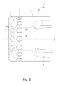
- Fig. 2 shows a side view of a part of the first auxiliary insulating element 8b with multiple first bypass channels 2 arranged in an annular manner around the axis z, preferably at predefined distances from one another.
- the dashed lines represent outlines which are not visible from the point of view of Fig. 2 .
- this first auxiliary insulating element 8b is made of PTFE, as well as is the (main) insulating nozzle 8a.
- the reference numerals of Fig. 2 indicate the same elements of Fig. 1 and will not be described again.
- the first bypass channels 2 may be straight or they may be curved or angled. Said shapes may even vary from channel to channel.
- a shape and an inclination angle of at least one of the first bypass channels 2 differs from a shape and an inclination angle of the others of the first bypass channels 2.
- the term "inclination” is understood in the context of this document as an inclination with respect to the longitudinal axis z. If the respective first bypass channel 2 has a shape which is not straight the inclination angle refers to a mean inclination angle of all channel sections or curvatures.
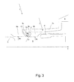
- Fig. 3 shows further embodiments like the ones of Fig. 1 with some differences. Additionally to the elements already described in connection with Fig. 1 this embodiment comprises a second auxiliary insulating element 8c which forms together with the insulating nozzle 8a a second channel 10.
- a plurality of second bypass channels 10 can be distributed substantially in an annular manner with respect to the longitudinal axis z at predefined mutual distances.
- Embodiments of the second bypass channel or channels 10 can include second auxiliary elements 8c with special shapes, e.g. with shapes including rails facing the front face 9a of the insulating nozzle 8a; such rails may impinge said front face 9a when the second bypass channel 10 is attached to the insulating nozzle 8a and can thereby form said second channels 10 as gaps between the rails.
- Suitable attachment means can be used to fix the second auxiliary element 8c to the insulating nozzle 8a, such that it may form an integral part of the insulating nozzle 8a.
- the second auxiliary element 8c may also be in single-piece or unitary with the insulating nozzle 8a.
- the second bypass channel 10 opens up on one side in the second section 7b of the first channel 7 and opens up on the other side in a second transitional area between the first section 7a of the first channel 7 and an inner wall 9d of the insulating element 8a.
- a ratio between a minimum cross-sectional area of the at least one second bypass channel 10 and a minimum cross-sectional area of the first channel 7a does not exceed 1.25.
- minimum cross-sectional area used in connection with the first bypass channel 2 and/or the second bypass channels 10 is understood as taking into account the totality of the respective channels present in the electrical switching device.
- the second bypass channel 10 opens up in the second transitional area at angles between a first reference line obtained by 5° anticlockwise rotation of the front face 9a and a second reference line obtained by 5° clockwise rotation of the inner surface 9d of the insulating element 8a.
- the two fluid streams meet immediately at the common opening of the two channels 7, 2 into the arcing volume 5, such that they mix instantaneously when they enter the arcing volume 5.
- a high turbulence is created in the arcing volume 5.
- Such a high turbulence is desired, because it helps cooling the fluid, which in turn cools, and eventually extinguishes, the electric arc.
- By adjusting the exit angle of the first bypass channel 2 it is furthermore possible to influence the direction of the turbulent layer resulting from the interaction of the fluid streams coming out of the first bypass channel 2 and the first channel 7 as to point towards the thinner portion of the electric arc.
- a further advantage of providing the first bypass channel 2 in the way described herein is that in the initial phase of fluid delivery from the pressurized gas volume 6 the fluid is delivered faster to the arcing volume 5 because of the shorter path.
- the present invention makes it possible to improve turbulence in the arcing volume of a circuit breaker or any other type of medium or high voltage electrical switch by arranging the first bypass channel in such a way that it opens into the arcing volume at a specific location: in the transitional area 11 between the front face 9b of the first auxiliary insulating element 8b and an inner wall 9c of the first auxiliary insulating element 8b.
- This design contributes to a faster extinction of electric arcs formed during switching operations of the switching device and, as a consequence, to more reliable switching devices.
- the fluid used in the electrical switching device 1 can be SF 6 gas or any other dielectric insulation medium, may it be gaseous and/or liquid, and in particular can be a dielectric insulation gas or arc quenching gas.
- dielectric insulation medium can for example encompass media, e.g.
- organofluorine compound such organofluorine compound being selected from the group consisting of: a fluoroether, a fluoroamine, a fluoroketone, an oxirane, a hydrofluorolefin, and mixtures thereof; and preferably being a fluoroketone and/or a fluoroether, more preferably a perfluoroketone and/or a hydrofluoroether.
- fluoroether fluoroamine
- fluoroketone refer to at least partially fluorinated compounds.
- fluoroether encompasses both hydrofluoroethers and perfluoroethers
- fluoroamine encompasses both hydrofluoroamines and perfluoroamines
- fluoroketone encompasses both hydrofluoroketones and perfluoroketones. It can thereby be preferred that the fluoroether, the fluoroamine, the fluoroketone and the oxirane are fully fluorinated, i.e. perfluorinated.
- fluoroketone as used in the context of the present invention shall be interpreted broadly and shall encompass both fluoromonoketones and fluorodiketones or generally fluoropolyketones. The term shall also encompass both saturated compounds and unsaturated compounds including double and/or triple bonds between carbon atoms.
- the at least partially fluorinated alkyl chain of the fluoroketones can be linear or branched and can optionally form a ring.
- the fluoroketone can be a fluoromonoketone and/or may also comprise heteroatoms, such as at least one of a nitrogen atom, oxygen atom and sulphur atom, replacing one or more carbon atoms.
- the fluoromonoketone, in particular perfluoroketone shall have from 3 to 15 or from 4 to 12 carbon atoms and particularly from 5 to 9 carbon atoms. Most preferably, it may comprise exactly 5 carbon atoms and/or exactly 6 carbon atoms and/or exactly 7 carbon atoms and/or exactly 8 carbon atoms.
- the dielectric insulation medium can further comprise, besides such admixture gases, a background gas or carrier gas different from the organofluorine compound, in particular different from the fluoroether, the fluoroamine, the fluoroketone, the oxirane and the hydrofluorolefin and preferably can be selected from the group consisting of: air, N 2 , O 2 , CO 2 , a noble gas, NO 2 , NO, N 2 O, fluorocarbons and in particular perfluorocarbons and preferably CF 4 , CF 3 I, SF 6 , and mixtures thereof.
- a background gas or carrier gas different from the organofluorine compound, in particular different from the fluoroether, the fluoroamine, the fluoroketone, the oxirane and the hydrofluorolefin and preferably can be selected from the group consisting of: air, N 2 , O 2 , CO 2 , a noble gas, NO 2 , NO, N 2 O, fluorocarbons
Abstract
An electrical switching device (1) comprises: a longitudinal axis (z), a contact arrangement with a first contact (3) and a second contact (4), an insulating element (8a) enclosing at least partly the first contact (3), and a first auxiliary insulating element (8b) enclosing at least partly the second contact (4). An arcing volume (5) is defined between the first contact (3) and the second contact (4) and delimited by inner walls of the insulating element (8a) and of the first auxiliary insulating element (8b) and is connected to a pressurized gas volume (6) via a first channel (7), in such a way that an insulating fluid can travel between both volumes (5, 6) through the first channel (7). The first channel (7) has a first section (7a) opening out in the arcing volume (5) and a second section (7b) opening out in the pressurized gas volume (6), the first section (7a) being delimited by a front face (9b) of the first auxiliary insulating element (8b) and at least by a front face (9a) of the insulating element (8a). In the first auxiliary insulating element (8b) at least a first bypass channel (2) is provided, which opens up on one side in the second section (7b) of the first channel (7) and opens up on the other side in a first transitional area (11) between the front face (9b) of the first auxiliary insulating element (8b) and an inner wall (9c) of the first auxiliary insulating element (8b).
Description
- The invention relates to the field of medium and high voltage switching technologies and concerns an electrical switching device and a method for operating the electrical switching device according to the independent claims, particularly for use as an earthing device, a fast-acting earthing device, a circuit breaker, a generator circuit breaker, a switch disconnector, a combined disconnector and earthing switch, or a load break switch in power transmission and distribution systems.
- Electrical switching devices are well known in the field of medium and high voltage switching applications. They are e.g. used for interrupting a current when an electrical fault occurs. As an example, circuit breakers have the task of opening contacts and keeping them far apart from one another in order to avoid a current flow, even in case of high electrical potential originating from the electrical fault itself. For the purposes of this disclosure the term medium voltage refers to voltages from 1 kV to 72.5 kV and the term high voltage refers to voltages higher than 72.5 kV. The electrical switching devices, like said circuit breakers, may have to be able to carry high nominal currents of 4000 A to 6300 A and to switch very high short circuit currents of 40 kA to 80 kA at very high voltages of 110 kV to 1200 kV.
- Because of the high nominal current the electrical switching devices of today require many so-called nominal contact fingers for the nominal current. When disconnecting (opening) a nominal or short circuit current within the electrical switching devices, the current commutates from the nominal contacts of the electrical switching device to its arcing contacts. Thus, when connecting (i.e. closing) the nominal contacts of the electric switching device, also the arcing contacts are connected. They normally comprise as one arcing contact arcing contact fingers arranged around the longitudinal axis of the electrical switching device in a so-called arcing finger cage or tulip and, as a mating arcing contact, a rod which is driven into the finger cage. However, there are also arrangements with two rods as arcing contacts, which are driven towards one another and are connected via their front faces during a closing operation.
- During the opening or closing process of the electrical switching device an electric arc forms between the two arcing contacts. In order to interrupt the current, the electrical switching devices contain a dielectrically inert fluid used as an insulating medium and to quench the electric arc. Quenching the electric arc means extracting as much energy as possible from it. Consequently, a part of the fluid located in the region where the electric arc is generated, called arcing volume, is considerably heated up (to around 20'000 °C to 30'000 °C) in a very short time period. Because of its volume expansion this part of the fluid builds up a pressure and is ejected from the arcing volume into a so-called expansion volume. In this way the electric arc is blown off around the instant when the current is zero. In some embodiments of circuit breakers an additional volume called heating volume or compression volume is used to heat up or pressurize gas located therein. This pressurized gas is then blown into the arcing volume in order to extinguish the electric arc.
- The
patent EP 0 753 873 describes a high voltage power switch with an insulating element having openings/channels connecting the heating volume mentioned above with the arcing volume. These extra channels open up directly into the arcing volume where the inner surface of both nozzles is substantially aligned with the breaker axis. - It is an objective of the present invention to further improve an electrical switching device with respect to its capabilities of cooling down or quenching an electric arc generated during switching operations.
- This objective is solved by the features of the independent claims. According to it, an electrical switching device with a contact arrangement having a longitudinal axis is provided. The contact arrangement comprises a first contact and a second contact. The two contacts are arranged coaxially with respect to one another and interact electrically and mechanically with one another for closing and opening the contact arrangement by moving at least one of the contacts along the longitudinal axis. The electrical switching device further comprises an insulating element enclosing at least partly the first contact and a first auxiliary insulating element enclosing at least partly the second contact. An arcing volume is defined between the first contact and the second contact and delimited by inner walls of the insulating element and of the first auxiliary insulating element. The arcing volume is connected to a pressurized gas volume via a first channel, in such a way that an insulating fluid can travel between the two volumes through the first channel. The first channel comprises a first section opening out in the arcing volume and of a second section opening out in the pressurized gas volume. The first section is delimited by a front face of the first auxiliary insulating element and at least by a front face of the insulating element. At least a first bypass channel is provided in the first auxiliary insulating element. The first bypass channel opens up on one side in the second section of the first channel and it opens up on the other side in a first transitional area between the front face of the first auxiliary insulating element and an inner wall of the first auxiliary insulating element.
- Furthermore, the objective is solved by a method for operating the electrical switching device according to the invention.
- Preferably an insulating fluid located in the electrical switching device is guided from a pressurized gas volume into an arcing volume in order to cool down or extinguish an electric arc generated during a switching operation of the first and the second contact in such a way that a fluid stream is split into a first stream travelling through the first channel and a second stream travelling through a plurality of first bypass channels arranged in an annular manner with respect to the longitudinal axis in the first auxiliary insulating element, and the first and the second stream are reunited immediately at a common opening of the first channel and of the first bypass channel into the arcing volume.
- By providing at least one first bypass channel and guiding a portion of insulating fluid through it, it is possible to further augment the turbulence of the fluid in the arcing volume, because a fluid stream originating from the first channel and a fluid stream originating from the at least one first bypass channel meet immediately when they enter the arcing volume, thus instantly creating turbulence therein. This is contrary to the above mentioned prior art, in which two distinct fluid streams enter the arcing volume separately and generate separate stream patterns with only a limited turbulence content until they meet. The measures according to the invention trigger the turbulent mixing in that part of the near-wall-region which is the most effective region for cooling the arc downstream of it.
- In embodiments the first and the second contact are arcing contacts forming a conductive path when the electrical switching device changes its switching state.
- In embodiments a third and a fourth contact are provided for carrying a nominal current when the electrical switching device is in a closed state.
- In other embodiments a plurality of first bypass channels are distributed substantially in an annular manner with respect to the longitudinal axis along the first auxiliary insulating element at predefined mutual distances.
- In one embodiment a second auxiliary insulation element is attached to the insulating element and is arranged in such a way that at least a second bypass channel is formed between the second auxiliary insulating element and the insulating element. The second bypass channel opens up on one side in the second section of the first channel and opens up on the other side in a second transitional area between the first section of the first channel and an inner wall of the insulating element.
- In embodiments the electrical switching device according to the invention comprises an insulating fluid in its interior. The fluid is selected from the group consisting of: SF6 gas, CO2 gas, SF6 gas with an admixture gas, CO2 gas with an admixture gas, any other switching gas or gas mixture, a liquid.
- Preferably, the electrical switching device according to the invention is used as an earthing device, a fast-acting earthing device, a circuit breaker, a generator circuit breaker, a switch disconnector, a combined disconnector and earthing switch, or a load break switch.
- Embodiments, advantages and applications of the invention result from the dependent claims and claim combinations and from the now following description in connection with the figures. It is shown in:
-
Fig. 1 a longitudinal sectional view of a part of an embodiment of an electrical switching device according to the invention; -
Fig. 2 a schematized side view of an embodiment of a first auxiliary insulating element; and -
Fig. 3 a longitudinal sectional view of the electrical switching device ofFig. 1 with a modified insulating element arrangement. - The invention is described for the example of a high voltage circuit breaker, of which only the arcing contacts are shown for clarity reasons. However, the principles described in the following also apply for the usage of the invention in other switching devices, e.g. of the type mentioned at the beginning.
- In the following same reference numerals denote structurally or functionally same elements of the various embodiments of the invention.
- The term fluid comprises all liquid and gaseous materials (e.g. SF6 gas, CO2 gas or gas mixtures comprising SF6 and/or CO2) having dielectric capabilities known to be required for a circuit breaker.
-
Fig. 1 shows a longitudinal sectional view of a part of an embodiment of acircuit breaker 1 in an opened configuration. Thedevice 1 is rotationally symmetric about a longitudinal axis z. Only the elements of thecircuit breaker 1 which are related to the present invention will be described in the following, other elements, e.g. nominal contacts, enclosure, etc, are not shown in the figures for clarity reasons. These elements are not immediately relevant for understanding the invention and are known as such by the skilled person in high voltage electrical engineering. - A "closed configuration" as used herein means that the nominal contacts and/or the arcing contacts of the circuit breaker are closed (i.e. electrically conductively connected to one another). Accordingly, an "opened configuration" as used herein means that the nominal contacts and/or the arcing contacts of the circuit breaker are opened (i.e. separated from one another).
- The
circuit breaker 1 comprises an arcing contact arrangement formed by afirst arcing contact 3 and asecond arcing contact 4. Thefirst arcing contact 3 is rod-shaped in this embodiment. Thesecond arcing contact 4 comprises multiple fingers arranged in a finger cage. This configuration is also known as tulip configuration. For the sake of clarity only one finger of the second arcing contact is shown inFig. 1 and3 and two such fingers are shown inFig. 2 . - It is assumed that an insulating fluid of the type mentioned herein is present inside the
circuit breaker 1. - For the explanatory purposes of the present invention it is assumed that only the
first arcing contact 3 is movable along the z-axis and thesecond arcing contact 4 is stationary. However, the invention is not limited to this configuration. Other configurations, e.g. double-motion interrupters, are possible as well, in which also the second arcing contact is movable. - An
insulating element 8a is arranged partly around thefirst arcing contact 3. In other words the insulatingelement 8a encloses thefirst arcing contact 3 concentrically and protrudes beyond it, as can be seen in the figures. This insulatingelement 8a is also known as the main insulatingnozzle 8a. A purpose of this insulatingnozzle 8a is to form a path, in combination with other elements of thecircuit breaker 1, for guiding the insulating fluid into and out of anarcing volume 5. - The arcing
volume 5 is a region in which thefirst arcing contact 3 is moved back and forth for closing or opening an arcing circuit. As known, in this region an electric arc develops during an opening and closing procedure between thefirst contact 3 and thesecond contact 4, which heats up the fluid located in thearc volume 5. Therefore, this region is also called heat-up volume and is defined or radially delimited by aninner wall 9d of the insulatingnozzle 8a and aninner wall 9c of the first auxiliary insulatingelement 8b, as well as is defined or axially delimited by the front extremity of the first arcing contact and the interior of the finger cage of thesecond arcing contact 4. - A first auxiliary insulating
element 8b is arranged facing the insulatingnozzle 8a, enclosing thesecond arcing contact 4 and protruding beyond it in the direction of the insulatingelement 8a to such an extent that it defines together with the insulatingelement 8a afirst section 7a of afirst channel 7. More precisely, afront face 9a of the duct-type insulating nozzle 8a and afront face 9b of the first auxiliary insulatingelement 8b define the walls of thefirst section 7a. Typically, thisfirst section 7a is arranged substantially transversally with respect to the longitudinal axis z. - The
channel 7 connects the arcingvolume 5 with apressurized gas volume 6 in such a way that said insulating fluid may travel between thesevolumes second section 7b is defined by a wall of the insulatingnozzle 8a and an outer wall of the first auxiliary insulatingelement 8b and is typically arranged substantially parallel to the longitudinal axis z. - The first auxiliary insulating
element 8b comprises multiplefirst bypass channels 2 connecting thesecond section 7b of thefirst channel 7 and atransition area 11 between a substantially longitudinal (with respect to the longitudinal axis z)inner wall 9c of the first auxiliary insulatingelement 8b and its substantially transversal (with respect to the longitudinal axis z)front face 9b. Typically, thistransitional area 11 is rounded. Only onefirst bypass channel 2 is shown inFig. 1 , a more detailed view is shown inFig. 2 . - In embodiments, a ratio between a minimum cross-sectional area of the at least one
first bypass channel 2 and a minimum cross-sectional area of thefirst channel 7a is greater than 0.25. - In further embodiments, the
first bypass channel 2 opens up in the firsttransitional area 11 at angles between a first reference line obtained by 5° clockwise rotation of thefront face 9b of the first auxiliary insulatingelement 8b and a second reference line obtained by 5° anticlockwise rotation of theinner wall 9c of the first auxiliary insulatingelement 8b. -
Fig. 2 shows a side view of a part of the first auxiliary insulatingelement 8b with multiplefirst bypass channels 2 arranged in an annular manner around the axis z, preferably at predefined distances from one another. The dashed lines represent outlines which are not visible from the point of view ofFig. 2 . Typically, this first auxiliary insulatingelement 8b is made of PTFE, as well as is the (main) insulatingnozzle 8a. The reference numerals ofFig. 2 indicate the same elements ofFig. 1 and will not be described again. In embodiments, thefirst bypass channels 2 may be straight or they may be curved or angled. Said shapes may even vary from channel to channel. Particularly, a shape and an inclination angle of at least one of thefirst bypass channels 2 differs from a shape and an inclination angle of the others of thefirst bypass channels 2. The term "inclination" is understood in the context of this document as an inclination with respect to the longitudinal axis z. If the respectivefirst bypass channel 2 has a shape which is not straight the inclination angle refers to a mean inclination angle of all channel sections or curvatures. -
Fig. 3 shows further embodiments like the ones ofFig. 1 with some differences. Additionally to the elements already described in connection withFig. 1 this embodiment comprises a second auxiliary insulatingelement 8c which forms together with the insulatingnozzle 8a asecond channel 10. - In embodiments, a plurality of
second bypass channels 10 can be distributed substantially in an annular manner with respect to the longitudinal axis z at predefined mutual distances. Embodiments of the second bypass channel orchannels 10 can include secondauxiliary elements 8c with special shapes, e.g. with shapes including rails facing thefront face 9a of the insulatingnozzle 8a; such rails may impinge saidfront face 9a when thesecond bypass channel 10 is attached to the insulatingnozzle 8a and can thereby form saidsecond channels 10 as gaps between the rails. Suitable attachment means can be used to fix the secondauxiliary element 8c to the insulatingnozzle 8a, such that it may form an integral part of the insulatingnozzle 8a. In other embodiments the secondauxiliary element 8c may also be in single-piece or unitary with the insulatingnozzle 8a. Thesecond bypass channel 10 opens up on one side in thesecond section 7b of thefirst channel 7 and opens up on the other side in a second transitional area between thefirst section 7a of thefirst channel 7 and aninner wall 9d of the insulatingelement 8a. - In embodiments, a ratio between a minimum cross-sectional area of the at least one
second bypass channel 10 and a minimum cross-sectional area of thefirst channel 7a does not exceed 1.25. - It is noted that the term "minimum cross-sectional area" used in connection with the
first bypass channel 2 and/or thesecond bypass channels 10 is understood as taking into account the totality of the respective channels present in the electrical switching device. - The
second bypass channel 10 opens up in the second transitional area at angles between a first reference line obtained by 5° anticlockwise rotation of thefront face 9a and a second reference line obtained by 5° clockwise rotation of theinner surface 9d of the insulatingelement 8a. - In the following the operation of the circuit breaker will be explained with a focus on the fluid flow, thus emphasizing the function of the
channels - As mentioned above an important objective during the design of high voltage or medium voltage switches is to extinguish as fast as possible the electric arc which forms during the switching operations. There are many solutions for this task, one of which consists in "blowing off" the electric arc (at the voltage zero crossing or current zero crossing) by means of the mentioned insulating fluid located inside the switching device (e.g. circuit breaker). For this, insulating fluid is compressed in the
pressurized gas volume 6 and is blown into the arcingvolume 5 with high pressure. In the present solution the insulating fluid is not only blown into the arcingvolume 5 through thefirst channel 7 but also through thefirst bypass channel 2. The two fluid streams meet immediately at the common opening of the twochannels volume 5, such that they mix instantaneously when they enter thearcing volume 5. Thus, a high turbulence is created in thearcing volume 5. Such a high turbulence is desired, because it helps cooling the fluid, which in turn cools, and eventually extinguishes, the electric arc. By adjusting the exit angle of thefirst bypass channel 2 it is furthermore possible to influence the direction of the turbulent layer resulting from the interaction of the fluid streams coming out of thefirst bypass channel 2 and thefirst channel 7 as to point towards the thinner portion of the electric arc. - A further advantage of providing the
first bypass channel 2 in the way described herein is that in the initial phase of fluid delivery from thepressurized gas volume 6 the fluid is delivered faster to the arcingvolume 5 because of the shorter path. - The present invention makes it possible to improve turbulence in the arcing volume of a circuit breaker or any other type of medium or high voltage electrical switch by arranging the first bypass channel in such a way that it opens into the arcing volume at a specific location: in the
transitional area 11 between thefront face 9b of the first auxiliary insulatingelement 8b and aninner wall 9c of the first auxiliary insulatingelement 8b. This design contributes to a faster extinction of electric arcs formed during switching operations of the switching device and, as a consequence, to more reliable switching devices. - For the purposes of this disclosure the fluid used in the
electrical switching device 1 can be SF6 gas or any other dielectric insulation medium, may it be gaseous and/or liquid, and in particular can be a dielectric insulation gas or arc quenching gas. Such dielectric insulation medium can for example encompass media, e.g. as admixture gas or admixture gases, comprising an organofluorine compound, such organofluorine compound being selected from the group consisting of: a fluoroether, a fluoroamine, a fluoroketone, an oxirane, a hydrofluorolefin, and mixtures thereof; and preferably being a fluoroketone and/or a fluoroether, more preferably a perfluoroketone and/or a hydrofluoroether. Herein, the terms "fluoroether", "fluoroamine" and "fluoroketone" refer to at least partially fluorinated compounds. In particular, the term "fluoroether" encompasses both hydrofluoroethers and perfluoroethers, the term "fluoroamine" encompasses both hydrofluoroamines and perfluoroamines, and the term "fluoroketone" encompasses both hydrofluoroketones and perfluoroketones. It can thereby be preferred that the fluoroether, the fluoroamine, the fluoroketone and the oxirane are fully fluorinated, i.e. perfluorinated. - In particular, the term "fluoroketone" as used in the context of the present invention shall be interpreted broadly and shall encompass both fluoromonoketones and fluorodiketones or generally fluoropolyketones. The term shall also encompass both saturated compounds and unsaturated compounds including double and/or triple bonds between carbon atoms. The at least partially fluorinated alkyl chain of the fluoroketones can be linear or branched and can optionally form a ring.
- In particular, the fluoroketone can be a fluoromonoketone and/or may also comprise heteroatoms, such as at least one of a nitrogen atom, oxygen atom and sulphur atom, replacing one or more carbon atoms. More preferably, the fluoromonoketone, in particular perfluoroketone, shall have from 3 to 15 or from 4 to 12 carbon atoms and particularly from 5 to 9 carbon atoms. Most preferably, it may comprise exactly 5 carbon atoms and/or exactly 6 carbon atoms and/or exactly 7 carbon atoms and/or exactly 8 carbon atoms.
- The dielectric insulation medium can further comprise, besides such admixture gases, a background gas or carrier gas different from the organofluorine compound, in particular different from the fluoroether, the fluoroamine, the fluoroketone, the oxirane and the hydrofluorolefin and preferably can be selected from the group consisting of: air, N2, O2, CO2, a noble gas, NO2, NO, N2O, fluorocarbons and in particular perfluorocarbons and preferably CF4, CF3I, SF6, and mixtures thereof.
- While there are shown and described presently preferred embodiments of the invention, it is to be distinctly understood that the invention is not limited thereto but may otherwise variously be embodied and practised within the scope of the following claims. Therefore, terms like "preferred" or "in particular" or "particularly" or "advantageously", etc. signify optional and exemplary embodiments only.
-
- 1
- = basic circuit breaker
- 2
- = first bypass channel
- 3
- = first arcing contact
- 4
- = second arcing contact
- 5
- = arcing volume
- 6
- = pressurized gas volume
- 7
- = first channel
- 7a
- = first section of first channel
- 7b
- = second section of first channel
- 8a
- = insulating element, main insulating nozzle
- 8b
- = first auxiliary insulating element
- 8c
- = second auxiliary insulating element
- 9a
- = front face of insulating element
- 9b
- = front face of first auxiliary insulating element
- 9c
- = inner wall of first auxiliary insulating element
- 9d
- = inner wall of insulating element
- 10
- = second bypass channel
- 11
- = first transition area
- z
- = longitudinal axis
Claims (13)
- Electrical switching device (1) with a contact arrangement having a longitudinal axis (z), wherein the contact arrangement comprises
a first contact (3) and a second contact (4), arranged coaxially with respect to one another and interacting electrically and mechanically with one another for closing and opening the contact arrangement by moving at least one of the contacts (3, 4) along the longitudinal axis (z),
wherein the electrical switching device further comprises an insulating element (8a) enclosing at least partly the first contact (3) and a first auxiliary insulating element (8b) enclosing at least partly the second contact (4),
wherein an arcing volume (5) is defined between the first contact (3) and the second contact (4) and delimited by inner walls of the insulating element (8a) and of the first auxiliary insulating element (8b) and is connected to a pressurized gas volume (6) via a first channel (7), in such a way that an insulating fluid can travel between the two volumes (5, 6) through the first channel (7),
wherein the first channel (7) comprising a first section (7a) opening out in the arcing volume (5) and of a second section (7b) opening out in the pressurized gas volume (6), wherein the first section (7a) is delimited by a front face (9b) of the first auxiliary insulating element (8b) and at least by a front face (9a) of the insulating element (8a),
wherein at least a first bypass channel (2) is provided in the first auxiliary insulating element (8b), wherein the first bypass channel (2) opens up on one side in the second section (7b) of the first channel (7),
characterized in that the first bypass channel (2) opens up on the other side in a first transitional area (11) between the front face (9b) of the first auxiliary insulating element (8b) and an inner wall (9c) of the first auxiliary insulating element (8b). - Electrical switching device (1) according to claim 1, wherein the first contact (3) and the second contact (4) are arcing contacts forming a conductive path when the electrical switching device changes its switching state, particularly wherein a third contact and a fourth contact are provided for carrying a nominal current when the electrical switching device is in a closed state.
- Electrical switching device (1) according to any one of the preceding claims, wherein a plurality of first bypass channels (2) are distributed substantially in an annular manner with respect to the longitudinal axis (z) along the first auxiliary insulating element (8b) at predefined mutual distances, particularly wherein a shape and/or an inclination angle of at least one of the first bypass channels (2) differs from a shape and/or an inclination angle of the others of the first bypass channels (2).
- Electrical switching device (1) according to any one of the preceding claims, wherein a ratio between a minimum cross-sectional area of the at least one first bypass channel (2) and a minimum cross-sectional area of the first channel (7a) is greater than 0.25.
- Electrical switching device (1) according to any one of the preceding claims, wherein the first bypass channel (2) opens up in the first transitional area (11) at angles between a first reference line obtained by 5° clockwise rotation of the front face (9b) of the first auxiliary insulating element (8b) and a second reference line obtained by 5° anticlockwise rotation of the inner wall (9c) of the first auxiliary insulating element (8b).
- Electrical switching device (1) according to one of the preceding claims, wherein a second auxiliary insulation element (8c) is attached to the insulating element (8a) and arranged in such a way that at least a second bypass channel (10) is formed between the second auxiliary insulating element (8c) and the insulating element (8a), wherein the second bypass channel (10) opens up on one side in the second section (7b) of the first channel (7) and opens up on the other side in a second transitional area between the first section (7a) of the first channel (7) and an inner wall (9d) of the insulating element (8a).
- Electrical switching device (1) according to any one of the preceding claims, wherein a plurality of second bypass channels (10) are distributed substantially in an annular manner with respect to the longitudinal axis (z) at predefined mutual distances.
- Electrical switching device (1) according to any one of the preceding claims, wherein a ratio between a minimum cross-sectional area of the at least one second bypass channel (10) and a minimum cross-sectional area of the first channel (7a) does not exceed 1.25.
- Electrical switching device (1) according to any one of the preceding claims, wherein the second bypass channel (10) opens up in the second transitional area at angles between a first reference line obtained by 5° anticlockwise rotation of the front face (9a) and a second reference line obtained by 5° clockwise rotation of the inner surface (9d) of the insulating element (8a).
- Electrical switching device (1) according to any one of the preceding claims, comprising an insulating fluid in its interior, wherein the fluid is selected from the group consisting of: SF6 gas, CO2 gas, SF6 gas with an admixture gas, CO2 gas with an admixture gas, any other switching gas or gas mixture, a liquid.
- Method for operating the electrical switching device (1) according to any one of the preceding claims.
- Method according to claim 11, wherein an insulating fluid located in the electrical switching device is guided from a pressurized gas volume (6) into an arcing volume (5) in order to cool down or extinguish an electric arc generated during a switching operation of the first contact (3) and the second contact (4) in such a way that a fluid stream is split into a first stream travelling through the first channel (7) and a second stream travelling through a plurality of first bypass channels (2) arranged in an annular manner with respect to the longitudinal axis (z) in the first auxiliary insulating element (8b), and the first stream and the second stream are reunited immediately at a common opening of the first channel (7) and of the first bypass channel (2) into the arcing volume (5).
- Use of the electrical switching device (1) according to any one of the claims 1 to 10 as an earthing device, a fast-acting earthing device, a circuit breaker, a generator circuit breaker, a switch disconnector, a combined disconnector and earthing switch, or a load break switch.
Priority Applications (1)
| Application Number | Priority Date | Filing Date | Title |
|---|---|---|---|
| EP13177036.4A EP2827353A1 (en) | 2013-07-18 | 2013-07-18 | Electrical switching device |
Applications Claiming Priority (1)
| Application Number | Priority Date | Filing Date | Title |
|---|---|---|---|
| EP13177036.4A EP2827353A1 (en) | 2013-07-18 | 2013-07-18 | Electrical switching device |
Publications (1)
| Publication Number | Publication Date |
|---|---|
| EP2827353A1 true EP2827353A1 (en) | 2015-01-21 |
Family
ID=48793116
Family Applications (1)
| Application Number | Title | Priority Date | Filing Date |
|---|---|---|---|
| EP13177036.4A Withdrawn EP2827353A1 (en) | 2013-07-18 | 2013-07-18 | Electrical switching device |
Country Status (1)
| Country | Link |
|---|---|
| EP (1) | EP2827353A1 (en) |
Cited By (1)
| Publication number | Priority date | Publication date | Assignee | Title |
|---|---|---|---|---|
| EP3739609A1 (en) * | 2019-05-14 | 2020-11-18 | ABB Power Grids Switzerland AG | Nozzle for a circuit breaker, circuit breaker, and method of 3d printing a nozzle for a circuit breaker |
Citations (4)
| Publication number | Priority date | Publication date | Assignee | Title |
|---|---|---|---|---|
| DE2911633A1 (en) * | 1979-03-24 | 1980-09-25 | Licentia Gmbh | Circuit breaker with gas jet arc extinction - incorporates low pressure channel to increase gas flow |
| DE2936132A1 (en) * | 1979-08-15 | 1981-02-26 | Bbc Brown Boveri & Cie | CIRCUIT BREAKER |
| US5453591A (en) * | 1994-04-05 | 1995-09-26 | Abb Power T&D Company Inc. | Sensing structure for component wear in high voltage circuit interrupters |
| EP0753873A1 (en) | 1995-07-13 | 1997-01-15 | Siemens Aktiengesellschaft | High voltage circuit breaker with an insulating body |
-
2013
- 2013-07-18 EP EP13177036.4A patent/EP2827353A1/en not_active Withdrawn
Patent Citations (4)
| Publication number | Priority date | Publication date | Assignee | Title |
|---|---|---|---|---|
| DE2911633A1 (en) * | 1979-03-24 | 1980-09-25 | Licentia Gmbh | Circuit breaker with gas jet arc extinction - incorporates low pressure channel to increase gas flow |
| DE2936132A1 (en) * | 1979-08-15 | 1981-02-26 | Bbc Brown Boveri & Cie | CIRCUIT BREAKER |
| US5453591A (en) * | 1994-04-05 | 1995-09-26 | Abb Power T&D Company Inc. | Sensing structure for component wear in high voltage circuit interrupters |
| EP0753873A1 (en) | 1995-07-13 | 1997-01-15 | Siemens Aktiengesellschaft | High voltage circuit breaker with an insulating body |
Cited By (2)
| Publication number | Priority date | Publication date | Assignee | Title |
|---|---|---|---|---|
| EP3739609A1 (en) * | 2019-05-14 | 2020-11-18 | ABB Power Grids Switzerland AG | Nozzle for a circuit breaker, circuit breaker, and method of 3d printing a nozzle for a circuit breaker |
| WO2020229338A1 (en) * | 2019-05-14 | 2020-11-19 | Abb Power Grids Switzerland Ag | Nozzle for a circuit breaker, circuit breaker, and method of 3d printing a nozzle for a circuit breaker |
Similar Documents
| Publication | Publication Date | Title |
|---|---|---|
| CN109564832B (en) | Gas-insulated low-voltage or medium-voltage load-break switch | |
| US10553378B2 (en) | Electrical circuit breaker device with particle trap | |
| US11699559B2 (en) | Device for interrupting non-short circuit currents only, in particular disconnector or earthing switch | |
| EP2827353A1 (en) | Electrical switching device | |
| US20230420203A1 (en) | Electrical switching device | |
| US10727013B2 (en) | Gas-insulated low- or medium-voltage switch with swirling device | |
| CN110770868B (en) | Gas-insulated load break switch and switchgear comprising a gas-insulated load break switch | |
| CN111630622B (en) | Gas-insulated high-or medium-voltage circuit breaker | |
| EP2954548A1 (en) | Contact arrangement and electrical switching device with such contact arrangement | |
| US20140174895A1 (en) | Contact arrangement for high voltage switchgear with contact arrangement | |
| CN111466006B (en) | Gas-insulated high-voltage or medium-voltage circuit breaker | |
| EP3611745B1 (en) | Gas-insulated low- or medium-voltage load break switch | |
| EP3477675B1 (en) | Gas-insulated medium-voltage switch with shield device | |
| CN117616528A (en) | Gas-insulated high-voltage or medium-voltage circuit breaker | |
| WO2023174675A1 (en) | Interrupter unit for gas-insulated high or medium voltage device and gas-insulated high or medium voltage device | |
| CN115136271A (en) | Tulip-arc contact with optimized flow slit and integrated pressure relief feature | |
| JP2017199616A (en) | Gas circuit breaker |
Legal Events
| Date | Code | Title | Description |
|---|---|---|---|
| 17P | Request for examination filed |
Effective date: 20130718 |
|
| AK | Designated contracting states |
Kind code of ref document: A1 Designated state(s): AL AT BE BG CH CY CZ DE DK EE ES FI FR GB GR HR HU IE IS IT LI LT LU LV MC MK MT NL NO PL PT RO RS SE SI SK SM TR |
|
| AX | Request for extension of the european patent |
Extension state: BA ME |
|
| PUAI | Public reference made under article 153(3) epc to a published international application that has entered the european phase |
Free format text: ORIGINAL CODE: 0009012 |
|
| STAA | Information on the status of an ep patent application or granted ep patent |
Free format text: STATUS: THE APPLICATION IS DEEMED TO BE WITHDRAWN |
|
| 18D | Application deemed to be withdrawn |
Effective date: 20150722 |