EP3739339A1 - Specimen processing system - Google Patents
Specimen processing system Download PDFInfo
- Publication number
- EP3739339A1 EP3739339A1 EP18900546.5A EP18900546A EP3739339A1 EP 3739339 A1 EP3739339 A1 EP 3739339A1 EP 18900546 A EP18900546 A EP 18900546A EP 3739339 A1 EP3739339 A1 EP 3739339A1
- Authority
- EP
- European Patent Office
- Prior art keywords
- module
- specimen
- holder
- housing
- stock
- Prior art date
- Legal status (The legal status is an assumption and is not a legal conclusion. Google has not performed a legal analysis and makes no representation as to the accuracy of the status listed.)
- Granted
Links
Images



Classifications
-
- G—PHYSICS
- G01—MEASURING; TESTING
- G01N—INVESTIGATING OR ANALYSING MATERIALS BY DETERMINING THEIR CHEMICAL OR PHYSICAL PROPERTIES
- G01N35/00—Automatic analysis not limited to methods or materials provided for in any single one of groups G01N1/00 - G01N33/00; Handling materials therefor
- G01N35/02—Automatic analysis not limited to methods or materials provided for in any single one of groups G01N1/00 - G01N33/00; Handling materials therefor using a plurality of sample containers moved by a conveyor system past one or more treatment or analysis stations
- G01N35/04—Details of the conveyor system
-
- G—PHYSICS
- G01—MEASURING; TESTING
- G01N—INVESTIGATING OR ANALYSING MATERIALS BY DETERMINING THEIR CHEMICAL OR PHYSICAL PROPERTIES
- G01N35/00—Automatic analysis not limited to methods or materials provided for in any single one of groups G01N1/00 - G01N33/00; Handling materials therefor
- G01N35/02—Automatic analysis not limited to methods or materials provided for in any single one of groups G01N1/00 - G01N33/00; Handling materials therefor using a plurality of sample containers moved by a conveyor system past one or more treatment or analysis stations
- G01N35/026—Automatic analysis not limited to methods or materials provided for in any single one of groups G01N1/00 - G01N33/00; Handling materials therefor using a plurality of sample containers moved by a conveyor system past one or more treatment or analysis stations having blocks or racks of reaction cells or cuvettes
-
- G—PHYSICS
- G01—MEASURING; TESTING
- G01N—INVESTIGATING OR ANALYSING MATERIALS BY DETERMINING THEIR CHEMICAL OR PHYSICAL PROPERTIES
- G01N35/00—Automatic analysis not limited to methods or materials provided for in any single one of groups G01N1/00 - G01N33/00; Handling materials therefor
- G01N35/02—Automatic analysis not limited to methods or materials provided for in any single one of groups G01N1/00 - G01N33/00; Handling materials therefor using a plurality of sample containers moved by a conveyor system past one or more treatment or analysis stations
- G01N35/04—Details of the conveyor system
- G01N2035/0401—Sample carriers, cuvettes or reaction vessels
- G01N2035/0406—Individual bottles or tubes
-
- G—PHYSICS
- G01—MEASURING; TESTING
- G01N—INVESTIGATING OR ANALYSING MATERIALS BY DETERMINING THEIR CHEMICAL OR PHYSICAL PROPERTIES
- G01N35/00—Automatic analysis not limited to methods or materials provided for in any single one of groups G01N1/00 - G01N33/00; Handling materials therefor
- G01N35/02—Automatic analysis not limited to methods or materials provided for in any single one of groups G01N1/00 - G01N33/00; Handling materials therefor using a plurality of sample containers moved by a conveyor system past one or more treatment or analysis stations
- G01N35/04—Details of the conveyor system
- G01N2035/0401—Sample carriers, cuvettes or reaction vessels
- G01N2035/0427—Sample carriers, cuvettes or reaction vessels nestable or stockable
-
- G—PHYSICS
- G01—MEASURING; TESTING
- G01N—INVESTIGATING OR ANALYSING MATERIALS BY DETERMINING THEIR CHEMICAL OR PHYSICAL PROPERTIES
- G01N35/00—Automatic analysis not limited to methods or materials provided for in any single one of groups G01N1/00 - G01N33/00; Handling materials therefor
- G01N35/02—Automatic analysis not limited to methods or materials provided for in any single one of groups G01N1/00 - G01N33/00; Handling materials therefor using a plurality of sample containers moved by a conveyor system past one or more treatment or analysis stations
- G01N35/04—Details of the conveyor system
- G01N2035/046—General conveyor features
- G01N2035/0462—Buffers [FIFO] or stacks [LIFO] for holding carriers between operations
Definitions
- the present invention pertains to a specimen processing system into which a plurality of modules are incorporated and relates to a technology which promotes space saving of the specimen processing system.
- Specimens of blood, urine and so forth which are provided by a patient and others are subjected to analysis for clinical examinations by using the specimen processing system in hospitals and examination facilities.
- preprocessing such as centrifugal separation, plug-opening and dispensation is performed by dedicated modules.
- a put-in module which puts the specimen in a module which performs the preprocessing and a housing module which houses the specimen whose analysis is finished are incorporated into the specimen processing system.
- Patent Literature 1 it is disclosed that in the specimen processing system into which the plurality of modules are incorporated, an empty holder which is a holder which finishes housing a specimen is conveyed to a loop-shaped empty holder conveyance path and the empty holder which is needed when the specimen is to be put therein is supplied from the empty holder conveyance path to a main conveyance path.
- Patent Literature 1 Japanese Patent Application Laid-Open No. 2015-121562
- the empty holder which finishes housing the specimen is not necessarily stocked in the stock module and may be directly used for putting the specimen therein. That is, the number of the empty holders which are stocked in the stock module can be suppressed by appropriately conveying the empty holder which finishes housing the specimen.
- the present invention aims to provide a specimen processing system which can contribute to space saving.cc Solution to Problem
- the present invention is a specimen processing system which includes a put-in module which puts a specimen on a put-in tray in a holder, a housing module which houses the specimen from the holder in a housing tray and a stock module which stocks the holder, in which an empty holder which is generated because the specimen is housed is directly conveyed to the put-in module without being conveyed to the stock module and is used for putting a new specimen therein.
- the specimen processing system which can contribute to the space saving.
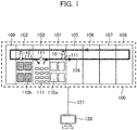
- a specimen processing system 100 of the present embodiment is equipped with a put-in module 101, a housing module 102, a stock module 103, a centrifugal separation module 105, a plug-opening module 106, a dispensing module 107, an analysis module 108, a plug-closing module 109, and a computer 120 for control.
- a specimen 10 which is put on a put-in tray 110a is transferred to a holder 111 which flows on a main conveyance path 104. That is, the specimen 10 is put therein.
- the put-in tray 110a is a carrier on which a plurality of numbers, for example, fifty to one hundred specimens 10 are put and the specimens 10 which are processing objects are put thereon.
- the specimens 10 are blood, urine and so forth which are collected from a patient and are put in containers having openable-closable plugs. Barcodes and so forth which are used for identification of the specimens 10 are pasted on the containers.
- the holder 111 is a carrier on which one specimen 10 is put. Incidentally, the holder 111 on which no specimen 10 is put is called an empty holder and the holder 111 on which the specimen 10 is put is called a mounted holder.
- centrifugal separation processing is performed on the specimen 10 and the specimen 10 is separated into each component.
- plug-opening module 105 a plug of the container of the specimen 10 is opened.
- dispensing module 107 dispensing processing is performed on the specimen 10.
- analysis module 108 the specimen 10 is analyzed.
- the analyzed specimen 10 is conveyed to the plug-closing module 109 passing through the respective modules in order of the dispensing module 107, the plug-opening module 106, the centrifugal separation module 105, the put-in module 101, the stock module 103, and the housing module 102.
- the plug-closing module 109 the plug of the container of the specimen 10 is closed.
- the specimen 10 that a series of processing thereon is terminated is transferred from the holder 111 to a housing tray 110b. That is, the specimen 10 is housed and the mounted holder becomes the empty holder.
- the housing tray 110b is a carrier on which the plurality of numbers, for example, fifty to one thousand specimens 10 are put similarly to the put-in tray 110a. However, a purpose of use thereof is different from that of the put-in tray 110a and the specimen 10 that the series of processing thereon is terminated is put thereon.
- the stock module 103 collection of the empty holder which is generated in the housing module 102, stocking of the plurality of holders 111 and supply of the holder 111 to the put-in module 101 are performed.
- a flow of the holder 111 in the stock module 103 will be described later using Fig. 2 and Fig. 3 while correlating with detailed structures and operations of the put-in module 101 and the housing module 102.
- the computer 120 for control is connected with each module via a communication line 121 and controls the operation of each module on the basis of information which is acquired by sensors and so forth that each module has.
- the computer 120 for control identifies the type of the specimen 10, for example, by inquiring a data list which is stored in the computer 120 for control about information which is acquired by reading out the barcode on the specimen 10 and makes it skip the processing in each module as required. More specifically, when the control use computer 120 identifies that the specimen 10 is urine, it makes it skip the processing in the centrifugal separation module 105 because the centrifugal separation processing is not necessary for the urine.
- the housing module 102 has a specimen sensor 201 which is a sensor for sensing the specimen 10 which reaches the housing module 102.
- the put-in module 1012 has a tray sensor 202 which is a sensor for sensing the put-in tray 110a in the put-in module 101.
- the stock module 103 is arranged between the housing module 102 and the put-in module 101 and has a straight advance path 203 and a supply path 204 and a collection path 205.
- the straight advance path 203 is a path for advancing the empty holder which is generated in the housing module 102 straight and conveying it to the main conveyance path 104 without stocking it in the stock module 103.
- the supply path 204 is a path for supplying the holder 111 which is stocked in the stock module 103 to the main conveyance path 104.
- the collection path 205 is a path for collecting the holder 111 and the collected holder 111 is stocked in the stock module 103.
- FIG. 3 A flowchart pertaining to the flow of the holder 111 in the stock module 103 is shown in Fig. 3 and respective steps will be explained.
- the computer 120 for control decides whether a housed specimen which is a specimen to be housed reaches the housing module 102 on the basis of a sensing signal from the specimen sensor 201.
- the process proceeds to S302 and when it is not sensed, the process proceeds to S306.
- another sensor for example, a sensor for sensing the holder 111 may be used, not limited to the specimen sensor 201.
- the computer 120 for control instructs the housing module 102 to transfer the housed specimen to the housing tray 110b. That is, the specimen 10 is housed therein and the empty holder is generated. A not illustrated chuck mechanism is used for transfer of the housed specimen.
- the computer 120 for control decides whether a put-in specimen which is a specimen to be put in is present in the put-in module 101 on the basis of a sensing signal from the tray sensor 202.
- toe process proceeds to S304 and when the put-in specimen is not present, the process proceeds to S308.
- the empty holder which is generated in S302 is conveyed to the straight advance path 203 and is used for putting a new specimen 10 therein in the put-in module 101.
- a sensor for sensing each specimen 10 on the put-in tray 110a may be used, not limited to the tray sensor 202.
- the computer 120 for control instructs the put-in module 101 to transfer the put-in specimen on the put-in tray 110a to the empty holder on the main conveyance path 104. That is, the specimen 10 which is the processing object is put therein and the mounted holder is generated. A not illustrated chuck mechanism is used for transfer of the put-in specimen.
- the computer 120 for control instructs each module to convey the mounting holder to the centrifugal separation module 105 and so forth such that predetermined processing is performed on the basis of barcode reading.
- the computer 120 for control decides whether the put-in specimen which is the specimen to be put in is present in the put-in module 101 on the basis of the sensing signal from the tray sensor 202.
- the process proceeds to S307 and when the put-in specimen is not present, the process returns to S301.
- another sensor may be used, not limited to the tray sensor 202.
- the computer 120 for control makes the stock module 103 supply the empty holder. That is, the holder 111 which is stocked in the stock module 103 is conveyed to the supply path 204.
- the empty holder which is conveyed to the supply path 204 is used for putting a new specimen 10 therein in the put-in module 101.
- the computer 120 for control makes the stock module 103 collect the empty holder. That is, the empty holder which is generated in the housing module 102 is conveyed to the collection path 205. The empty holder is collected and thereby the empty holders which stay on the main conveyance path 104 can be reduced.
- the specimen processing system 100 which can contribute to the space saving.
- it is decided whether the empty holder which finishes housing the specimen is directly conveyed to the put-in module 101 without stocking it in the stock module 103 or is once stocked in the stock module 103 in accordance with presence/absence of the put-in specimen unnecessary staying of the empty holder and upsizing of the stock module 103 which accompanies therewith can be avoided. Upsizing of the stock module 103 is not needed and thereby the space saving of the specimen processing system can be promoted.
- the housing module 102 and the put-in module 101 may be integrated with each other.
- the housing module 102 and the put-in module 101 are integrated with each other.
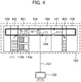
- the specimen processing system 100 is equipped with a put-in/housing integrated module 401, a supply stock module 402, a collection stock module 403, the centrifugal separation module 105, the plug-opening module 106, the dispensing module 107, the analysis module 108, the plug-closing module 109, and the computer 120 for control.
- the put-in/housing integrated module 401, the supply stock module 402 and the collection stock module 403 which are configurations which are different from those in the first embodiment will be described.
- the put-in/housing integrated module 401 is a module that the housing module 102 and the put-in module 101 in the first embodiment are integrated with each other by being arranged adjacent to each other and performs transfer of the specimen 10 from the mounted holder to the housing tray 110b and transfer of the specimen 10 from the put-in tray 110a to the empty holder. That is, it performs housing and putting-in of the specimen 10.
- the holder 111 which is stocked in the supply stock module 402 is supplied to the main conveyance path 104 as required.
- the collection stock module 403 the empty holder which flows on the main conveyance path 104 is collected. A flow of processing that the holder 111 is supplied or collected will be described later by using Fig. 6 .
- the put-in/housing integrated module 401 has the specimen sensor 201 which is the sensor for sensing the specimen 10 which reaches the put-in/housing integrated module 401 and the tray sensor 202 which is the sensor for sensing the put-in tray 110a in the put-in/housing integrated module 401.
- the supply stock module 402 has the supply path 204 for supplying the holder 111 which is stocked in the supply stock module 402 to the main conveyance path 104.
- the collection stock module 403 has the collection path 205 for collecting the empty holder which reaches the collection stock module 403.
- the put-in/housing integrated module 401 may be arranged between the supply stock module 402 and the collection stock module 403 and the centrifugal separation module 105, the plug-opening module 106, the dispensing module 107 and so forth may be arranged between the put-in/housing integrated module 401 and the collection stock module 403.
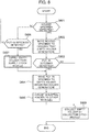
- FIG. 6 A flowchart pertaining to the flow of the holder 111 in the put-in/housing integrated module 401, the supply stock module 402, and the collection stock module 403 is shown in Fig. 6 and respective steps will be explained.
- the computer 120 for control decides whether the housed specimen reaches the put-in/housing integrated module 401 on the basis of the sensing signal from the specimen sensor 201.
- the process proceeds to S602 and when it is not sensed, the process proceeds to S606.
- another sensor may be used, not limited to the specimen sensor 201.
- the computer 120 for control instructs the put-in/housing integrated module 401 to transfer the housed specimen to the housing tray 110b. That is, the specimen 10 is housed and the empty holder is generated.
- the not illustrated chuck mechanism is used for transfer of the housed specimen.
- the computer 120 for control decides whether the put-in specimen is present in the put-in/housing integrated module 401 on the basis of the sensing signal from the tray sensor 202.
- the process proceeds to S604 and the empty holder which is generated in S602 is used for putting a new specimen 10 therein.
- the process proceeds to S608 and the empty holder which is generated in S602 flows on the main conveyance path 104.
- another sensor since in the present step, it is enough to make it possible to decide whether the put-in specimen is present in the put-in/housing integrated module 401, another sensor may be used, not limited to the tray sensor 202.
- the computer 120 for control instructs the put-in/housing integrated module 401 to transfer the put-in specimen on the put-in tray 110a to the empty holder on the main conveyance path 104. That is, the specimen 10 which is the processing object is put therein and the mounted holder is generated.
- the not illustrated chuck mechanism is used for transfer of the put-in specimen.
- the computer 120 for control instructs the respective modules to transfer the mounted holder to the centrifugal separation module 105 and so forth such that the predetermined processing is performed on the basis of barcode reading.
- the computer 120 for control decides whether the put-in specimen is present in the put-in/housing integrated module 401 on the basis of the sensing signal from the tray sensor 202.
- the process proceeds to S607 and when the put-in specimen is not present, the process returns to S601.
- another sensor may be used, not limited to the tray sensor 202.
- the computer 120 for control makes the supply stock module 402 supply the empty holder. That is, the holder 111 which is stocked in the supply stock module 402 is conveyed to the supply path 204.
- the empty holder which is conveyed to the supply path 204 is used for putting a new specimen 10 therein in the put-in/housing integrated module 401.
- the computer 120 for control makes the collection stock module 403 collect the empty holder. That is, the empty holder which reaches the collection stock module 403 is conveyed to the collection path 205.
- the empty holder which is collected in the present step is not limited to the empty holder which is generated in the put-in/housing integrated module 401, also empty holders which are generated in the centrifugal separation module 105, the plug-opening module 106, and the dispensing module 107 for some reason are included.
- the empty holders are collected and thereby the empty holders which stay on the main conveyance path 104 can be reduced.
- the mounted holder which reaches the collection stock module 403 is not collected and keeps flowing on the main conveyance path 104.
- the put-in module 101 and the housing module 102 are integrated with each other and the empty holder which finishes housing the specimen is directly used for putting the specimen therein, there can be provided the specimen processing system 100 which can contribute to the space saving.
- the empty holder which finishes housing the specimen is directly used for putting-in, the supply stock module 402 can be downsized.
- the empty holder which finishes housing the specimen is directly used for putting the specimen therein in the specimen processing system which is equipped with the put-in/housing integrated module.
- the empty holder is generated in the put-in/housing integrated module in the absence of the specimen to be put therein, unnecessary empty holders flow on the main conveyance path and reduce an operation rate of the specimen processing system. Accordingly, in the present embodiment, that the empty holder is transferred to a dedicated path which is different from the main conveyance path in order to avoid a reduction in operation rate will be explained. Incidentally, since the overall configuration of the present embodiment is the same as that of the second embodiment, explanation thereof is omitted.
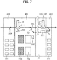
- the put-in/housing integrated module 401 has the specimen sensor 201 and the tray sensor 202 similarly to that in the second embodiment and has an empty holder dedicated path 701.
- the empty holder dedicated path 701 is a path which conveys only the empty holder.
- the supply stock module 402 is the same as that in the second embodiment.
- the collection stock module 403 has the collection path 205 similarly to that in the second embodiment and the empty holder dedicated path 701 is connected thereto. The empty holder which reaches the collection stock module 403 via the empty holder dedicated path 701 is collected and stocked in the collection stock module 403.
- the computer 120 for control decides whether the put-in specimen is present in the put-in/housing integrated module 401 on the basis of the sensing signal from the tray sensor 202.
- the process proceeds to S604 and when the put-in specimen is not present, the process proceeds to S608.
- the empty holder which is generated in S602 is conveyed to the empty holder dedicated path 701.
- the computer 120 for control makes the collection stock module 403 collect the empty holder.
- the empty holder which is generated in the put-in/housing integrated module 401 is collected via the empty holder dedicated path 701.
- empty holders which are generated in the centrifugal separation module 105, the plug-opening module 106 and the dispensing module 107 for some reason are collected via the collection path 205.
- the mounted holder which reaches the collection stock module 403 is not collected and keeps flowing on the main conveyance path 104.
- the empty holder which is generated in the put-in/housing integrated module 401 is conveyed to the collection stock module 403 via the empty holder dedicated path 701, the empty holders on the main conveyance path are reduced and it becomes possible to improve the operation rate of the specimen processing system 100.
- the space saving of the specimen processing system 100 owing to integration of the put-in module 101 with the housing module 102 and downsizing of the supply stock module 402 is the same as that in the second embodiment.
- the examination processing system of the present invention is not limited to the above-described embodiments and can be embodied by modifying constitutional elements within a range not deviating from the gist of the invention.
- a plurality of constitutional elements which are disclosed in the above-mentioned embodiments may be appropriately combined with one another. Further, some constitutional elements may be deleted from all the constitutional elements which are indicated in the above-described embodiments.
Landscapes
- Chemical & Material Sciences (AREA)
- Physics & Mathematics (AREA)
- Health & Medical Sciences (AREA)
- Life Sciences & Earth Sciences (AREA)
- Analytical Chemistry (AREA)
- Biochemistry (AREA)
- General Health & Medical Sciences (AREA)
- General Physics & Mathematics (AREA)
- Immunology (AREA)
- Pathology (AREA)
- Chemical Kinetics & Catalysis (AREA)
- Automatic Analysis And Handling Materials Therefor (AREA)
Abstract
Description
- The present invention pertains to a specimen processing system into which a plurality of modules are incorporated and relates to a technology which promotes space saving of the specimen processing system.
- Specimens of blood, urine and so forth which are provided by a patient and others are subjected to analysis for clinical examinations by using the specimen processing system in hospitals and examination facilities. In the specimen processing system, prior to the analysis of the specimens, preprocessing such as centrifugal separation, plug-opening and dispensation is performed by dedicated modules. Further, a put-in module which puts the specimen in a module which performs the preprocessing and a housing module which houses the specimen whose analysis is finished are incorporated into the specimen processing system. In Patent Literature 1, it is disclosed that in the specimen processing system into which the plurality of modules are incorporated, an empty holder which is a holder which finishes housing a specimen is conveyed to a loop-shaped empty holder conveyance path and the empty holder which is needed when the specimen is to be put therein is supplied from the empty holder conveyance path to a main conveyance path.
- Patent Literature 1: Japanese Patent Application Laid-Open No.
2015-121562 - However, in the specimen processing system which is disclosed in Patent Literature 1, since the empty holder which finishes housing the specimen is once stocked on the empty holder conveyance path and in a stock module which stocks the empty holder, there are cases where it is not suited for space saving of the system judging from the required number of the empty holders which are used in a facility. In a large-scale facility, hundreds to thousands of specimens are processed per day and the stock module is upsized so as to make it possible to stock the empty holders for the number of the processed ones.
- Incidentally, the empty holder which finishes housing the specimen is not necessarily stocked in the stock module and may be directly used for putting the specimen therein. That is, the number of the empty holders which are stocked in the stock module can be suppressed by appropriately conveying the empty holder which finishes housing the specimen.
- Accordingly, the present invention aims to provide a specimen processing system which can contribute to space saving.cc Solution to Problem
- In order to attain the above-mentioned aim, the present invention is a specimen processing system which includes a put-in module which puts a specimen on a put-in tray in a holder, a housing module which houses the specimen from the holder in a housing tray and a stock module which stocks the holder, in which an empty holder which is generated because the specimen is housed is directly conveyed to the put-in module without being conveyed to the stock module and is used for putting a new specimen therein. Advantageous Effects of the Invention
- According to the present invention, there can be provided the specimen processing system which can contribute to the space saving.
-
-
Fig. 1 is a diagram illustrating one example of an overall configuration of a specimen processing system of a first embodiment. -
Fig. 2 is a diagram explaining a detailed structure of the first embodiment. -
Fig. 3 is a diagram explaining a flowchart of the first embodiment. -
Fig. 4 is a diagram illustrating one example of an overall configuration of a specimen processing system of a second embodiment. -
Fig. 5 is a diagram explaining a detailed structure of the second embodiment. -
Fig. 6 is a diagram explaining a flowchart of the second embodiment. -
Fig. 7 is a diagram explaining a flow of an empty holder in a third embodiment. - In the following, the present embodiment will be described with reference to the drawings.
- As illustrated in
Fig. 1 , aspecimen processing system 100 of the present embodiment is equipped with a put-inmodule 101, ahousing module 102, astock module 103, acentrifugal separation module 105, a plug-opening module 106, adispensing module 107, ananalysis module 108, a plug-closing module 109, and acomputer 120 for control. - In the following, each part will be explained in processing order.
- In the put-in
module 101, aspecimen 10 which is put on a put-intray 110a is transferred to aholder 111 which flows on amain conveyance path 104. That is, thespecimen 10 is put therein. The put-intray 110a is a carrier on which a plurality of numbers, for example, fifty to one hundredspecimens 10 are put and thespecimens 10 which are processing objects are put thereon. Thespecimens 10 are blood, urine and so forth which are collected from a patient and are put in containers having openable-closable plugs. Barcodes and so forth which are used for identification of thespecimens 10 are pasted on the containers. Theholder 111 is a carrier on which onespecimen 10 is put. Incidentally, theholder 111 on which nospecimen 10 is put is called an empty holder and theholder 111 on which thespecimen 10 is put is called a mounted holder. - In the
centrifugal separation module 105, centrifugal separation processing is performed on thespecimen 10 and thespecimen 10 is separated into each component. In the plug-opening module 105, a plug of the container of thespecimen 10 is opened. In thedispensing module 107, dispensing processing is performed on thespecimen 10. In theanalysis module 108, thespecimen 10 is analyzed. - The analyzed
specimen 10 is conveyed to the plug-closing module 109 passing through the respective modules in order of thedispensing module 107, the plug-opening module 106, thecentrifugal separation module 105, the put-inmodule 101, thestock module 103, and thehousing module 102. In the plug-closing module 109, the plug of the container of thespecimen 10 is closed. - In the
housing module 102, thespecimen 10 that a series of processing thereon is terminated is transferred from theholder 111 to ahousing tray 110b. That is, thespecimen 10 is housed and the mounted holder becomes the empty holder. Thehousing tray 110b is a carrier on which the plurality of numbers, for example, fifty to one thousandspecimens 10 are put similarly to the put-intray 110a. However, a purpose of use thereof is different from that of the put-intray 110a and thespecimen 10 that the series of processing thereon is terminated is put thereon. - In the
stock module 103, collection of the empty holder which is generated in thehousing module 102, stocking of the plurality ofholders 111 and supply of theholder 111 to the put-inmodule 101 are performed. A flow of theholder 111 in thestock module 103 will be described later usingFig. 2 andFig. 3 while correlating with detailed structures and operations of the put-inmodule 101 and thehousing module 102. - The
computer 120 for control is connected with each module via acommunication line 121 and controls the operation of each module on the basis of information which is acquired by sensors and so forth that each module has. Thecomputer 120 for control identifies the type of thespecimen 10, for example, by inquiring a data list which is stored in thecomputer 120 for control about information which is acquired by reading out the barcode on thespecimen 10 and makes it skip the processing in each module as required. More specifically, when the control usecomputer 120 identifies that thespecimen 10 is urine, it makes it skip the processing in thecentrifugal separation module 105 because the centrifugal separation processing is not necessary for the urine. - The detailed structures of the
housing module 102, the put-inmodule 101, and thestock module 103 will be explained usingFig. 2 . Thehousing module 102 has aspecimen sensor 201 which is a sensor for sensing thespecimen 10 which reaches thehousing module 102. The put-in module 1012 has atray sensor 202 which is a sensor for sensing the put-intray 110a in the put-inmodule 101. - The
stock module 103 is arranged between thehousing module 102 and the put-inmodule 101 and has astraight advance path 203 and asupply path 204 and acollection path 205. Thestraight advance path 203 is a path for advancing the empty holder which is generated in thehousing module 102 straight and conveying it to themain conveyance path 104 without stocking it in thestock module 103. Thesupply path 204 is a path for supplying theholder 111 which is stocked in thestock module 103 to themain conveyance path 104. Thecollection path 205 is a path for collecting theholder 111 and the collectedholder 111 is stocked in thestock module 103. - A flowchart pertaining to the flow of the
holder 111 in thestock module 103 is shown inFig. 3 and respective steps will be explained. - The
computer 120 for control decides whether a housed specimen which is a specimen to be housed reaches thehousing module 102 on the basis of a sensing signal from thespecimen sensor 201. When the housed specimen is sensed, the process proceeds to S302 and when it is not sensed, the process proceeds to S306. Incidentally, since in the present step, it is enough to make it possible to decide whether the housed specimen reaches thehousing module 102, another sensor, for example, a sensor for sensing theholder 111 may be used, not limited to thespecimen sensor 201. - The
computer 120 for control instructs thehousing module 102 to transfer the housed specimen to thehousing tray 110b. That is, thespecimen 10 is housed therein and the empty holder is generated. A not illustrated chuck mechanism is used for transfer of the housed specimen. - The
computer 120 for control decides whether a put-in specimen which is a specimen to be put in is present in the put-inmodule 101 on the basis of a sensing signal from thetray sensor 202. When the put-in specimen is present, toe process proceeds to S304 and when the put-in specimen is not present, the process proceeds to S308. In a case where the process proceeds to S304, the empty holder which is generated in S302 is conveyed to thestraight advance path 203 and is used for putting anew specimen 10 therein in the put-inmodule 101. Incidentally, since in the present step, it is enough to make it possible to decide whether the put-in specimen is present in the put-inmodule 101, another sensor, for example, a sensor for sensing eachspecimen 10 on the put-intray 110a may be used, not limited to thetray sensor 202. - The
computer 120 for control instructs the put-inmodule 101 to transfer the put-in specimen on the put-intray 110a to the empty holder on themain conveyance path 104. That is, thespecimen 10 which is the processing object is put therein and the mounted holder is generated. A not illustrated chuck mechanism is used for transfer of the put-in specimen. - The
computer 120 for control instructs each module to convey the mounting holder to thecentrifugal separation module 105 and so forth such that predetermined processing is performed on the basis of barcode reading. - The
computer 120 for control decides whether the put-in specimen which is the specimen to be put in is present in the put-inmodule 101 on the basis of the sensing signal from thetray sensor 202. When the put-in specimen is present, the process proceeds to S307 and when the put-in specimen is not present, the process returns to S301. Incidentally, since in the present step, it is enough to make it possible to decide whether the put-in specimen is present in the put-inmodule 101, another sensor may be used, not limited to thetray sensor 202. - The
computer 120 for control makes thestock module 103 supply the empty holder. That is, theholder 111 which is stocked in thestock module 103 is conveyed to thesupply path 204. The empty holder which is conveyed to thesupply path 204 is used for putting anew specimen 10 therein in the put-inmodule 101. - The
computer 120 for control makes thestock module 103 collect the empty holder. That is, the empty holder which is generated in thehousing module 102 is conveyed to thecollection path 205. The empty holder is collected and thereby the empty holders which stay on themain conveyance path 104 can be reduced. - Owing to the above-described configuration, since the empty holder which finishes housing the specimen comes to be directly used for putting the specimen therein and the number of the
holders 111 which are stocked in the stock module 1033 can be reduced, there can be provided thespecimen processing system 100 which can contribute to the space saving. In particular, since it is decided whether the empty holder which finishes housing the specimen is directly conveyed to the put-inmodule 101 without stocking it in thestock module 103 or is once stocked in thestock module 103 in accordance with presence/absence of the put-in specimen, unnecessary staying of the empty holder and upsizing of thestock module 103 which accompanies therewith can be avoided. Upsizing of thestock module 103 is not needed and thereby the space saving of the specimen processing system can be promoted. - It was explained in the first embodiment that in the
specimen processing system 100 which is equipped with thehousing module 102, the put-inmodule 101 and thestock module 103, a conveyance destination of the empty holder which finishes housing the specimen is decided depending on presence/absence of the put-in specimen. For space saving of the specimen processing system, thehousing module 102 and the put-inmodule 101 may be integrated with each other. In the present embodiment, a case where thehousing module 102 and the put-inmodule 101 are integrated with each other will be explained. - An overall configuration of the
specimen processing system 100 of the present embodiment will be explained by usingFig. 4 . Thespecimen processing system 100 is equipped with a put-in/housing integratedmodule 401, asupply stock module 402, acollection stock module 403, thecentrifugal separation module 105, the plug-openingmodule 106, thedispensing module 107, theanalysis module 108, the plug-closingmodule 109, and thecomputer 120 for control. The put-in/housing integratedmodule 401, thesupply stock module 402 and thecollection stock module 403 which are configurations which are different from those in the first embodiment will be described. - The put-in/housing integrated
module 401 is a module that thehousing module 102 and the put-inmodule 101 in the first embodiment are integrated with each other by being arranged adjacent to each other and performs transfer of thespecimen 10 from the mounted holder to thehousing tray 110b and transfer of thespecimen 10 from the put-intray 110a to the empty holder. That is, it performs housing and putting-in of thespecimen 10. - In the
supply stock module 402, theholder 111 which is stocked in thesupply stock module 402 is supplied to themain conveyance path 104 as required. In thecollection stock module 403, the empty holder which flows on themain conveyance path 104 is collected. A flow of processing that theholder 111 is supplied or collected will be described later by usingFig. 6 . - Detailed structures of the put-in/housing integrated
module 401, thesupply stock module 402, and thecollection stock module 403 will be explained by usingFig. 5 . The put-in/housing integratedmodule 401 has thespecimen sensor 201 which is the sensor for sensing thespecimen 10 which reaches the put-in/housing integratedmodule 401 and thetray sensor 202 which is the sensor for sensing the put-intray 110a in the put-in/housing integratedmodule 401. Thesupply stock module 402 has thesupply path 204 for supplying theholder 111 which is stocked in thesupply stock module 402 to themain conveyance path 104. Thecollection stock module 403 has thecollection path 205 for collecting the empty holder which reaches thecollection stock module 403. The put-in/housing integratedmodule 401 may be arranged between thesupply stock module 402 and thecollection stock module 403 and thecentrifugal separation module 105, the plug-openingmodule 106, thedispensing module 107 and so forth may be arranged between the put-in/housing integratedmodule 401 and thecollection stock module 403. - A flowchart pertaining to the flow of the
holder 111 in the put-in/housing integratedmodule 401, thesupply stock module 402, and thecollection stock module 403 is shown inFig. 6 and respective steps will be explained. - The
computer 120 for control decides whether the housed specimen reaches the put-in/housing integratedmodule 401 on the basis of the sensing signal from thespecimen sensor 201. When the housed specimen is sensed, the process proceeds to S602 and when it is not sensed, the process proceeds to S606. Incidentally, since in the present step, it is enough to make it possible to decide whether the housed specimen reaches the put-in/housing integratedmodule 401, another sensor may be used, not limited to thespecimen sensor 201. - The
computer 120 for control instructs the put-in/housing integratedmodule 401 to transfer the housed specimen to thehousing tray 110b. That is, thespecimen 10 is housed and the empty holder is generated. The not illustrated chuck mechanism is used for transfer of the housed specimen. - The
computer 120 for control decides whether the put-in specimen is present in the put-in/housing integratedmodule 401 on the basis of the sensing signal from thetray sensor 202. When the put-in specimen is present, the process proceeds to S604 and the empty holder which is generated in S602 is used for putting anew specimen 10 therein. When the put-in specimen is not present, the process proceeds to S608 and the empty holder which is generated in S602 flows on themain conveyance path 104. Incidentally, since in the present step, it is enough to make it possible to decide whether the put-in specimen is present in the put-in/housing integratedmodule 401, another sensor may be used, not limited to thetray sensor 202. - The
computer 120 for control instructs the put-in/housing integratedmodule 401 to transfer the put-in specimen on the put-intray 110a to the empty holder on themain conveyance path 104. That is, thespecimen 10 which is the processing object is put therein and the mounted holder is generated. The not illustrated chuck mechanism is used for transfer of the put-in specimen. - The
computer 120 for control instructs the respective modules to transfer the mounted holder to thecentrifugal separation module 105 and so forth such that the predetermined processing is performed on the basis of barcode reading. - The
computer 120 for control decides whether the put-in specimen is present in the put-in/housing integratedmodule 401 on the basis of the sensing signal from thetray sensor 202. When the put-in specimen is present, the process proceeds to S607 and when the put-in specimen is not present, the process returns to S601. Incidentally, since in the present step, it is enough to make it possible to decide whether the put-in specimen is present in the put-in/housing integratedmodule 401, another sensor may be used, not limited to thetray sensor 202. - The
computer 120 for control makes thesupply stock module 402 supply the empty holder. That is, theholder 111 which is stocked in thesupply stock module 402 is conveyed to thesupply path 204. The empty holder which is conveyed to thesupply path 204 is used for putting anew specimen 10 therein in the put-in/housing integratedmodule 401. - The
computer 120 for control makes thecollection stock module 403 collect the empty holder. That is, the empty holder which reaches thecollection stock module 403 is conveyed to thecollection path 205. The empty holder which is collected in the present step is not limited to the empty holder which is generated in the put-in/housing integratedmodule 401, also empty holders which are generated in thecentrifugal separation module 105, the plug-openingmodule 106, and thedispensing module 107 for some reason are included. The empty holders are collected and thereby the empty holders which stay on themain conveyance path 104 can be reduced. Incidentally, the mounted holder which reaches thecollection stock module 403 is not collected and keeps flowing on themain conveyance path 104. - Owing to the above-explained configuration, since the put-in
module 101 and thehousing module 102 are integrated with each other and the empty holder which finishes housing the specimen is directly used for putting the specimen therein, there can be provided thespecimen processing system 100 which can contribute to the space saving. In particular, since the empty holder which finishes housing the specimen is directly used for putting-in, thesupply stock module 402 can be downsized. - It was explained in the second embodiment that the empty holder which finishes housing the specimen is directly used for putting the specimen therein in the specimen processing system which is equipped with the put-in/housing integrated module. When the empty holder is generated in the put-in/housing integrated module in the absence of the specimen to be put therein, unnecessary empty holders flow on the main conveyance path and reduce an operation rate of the specimen processing system. Accordingly, in the present embodiment, that the empty holder is transferred to a dedicated path which is different from the main conveyance path in order to avoid a reduction in operation rate will be explained. Incidentally, since the overall configuration of the present embodiment is the same as that of the second embodiment, explanation thereof is omitted.
- The detailed structures of the put-in/housing integrated
module 401, thesupply stock module 402 and thecollection stock module 403 will be explained by usingFig. 7 . The put-in/housing integratedmodule 401 has thespecimen sensor 201 and thetray sensor 202 similarly to that in the second embodiment and has an empty holderdedicated path 701. The empty holderdedicated path 701 is a path which conveys only the empty holder. Thesupply stock module 402 is the same as that in the second embodiment. Thecollection stock module 403 has thecollection path 205 similarly to that in the second embodiment and the empty holderdedicated path 701 is connected thereto. The empty holder which reaches thecollection stock module 403 via the empty holderdedicated path 701 is collected and stocked in thecollection stock module 403. - Since the flowchart of the present embodiment is the same as that in the second embodiment except S603 and S608, S603 and S608 will be explained here and explanation of other steps is omitted.
- The
computer 120 for control decides whether the put-in specimen is present in the put-in/housing integratedmodule 401 on the basis of the sensing signal from thetray sensor 202. When the put-in specimen is present, the process proceeds to S604 and when the put-in specimen is not present, the process proceeds to S608. In a case where the process proceeds to S608, the empty holder which is generated in S602 is conveyed to the empty holderdedicated path 701. - The
computer 120 for control makes thecollection stock module 403 collect the empty holder. The empty holder which is generated in the put-in/housing integratedmodule 401 is collected via the empty holderdedicated path 701. In addition, empty holders which are generated in thecentrifugal separation module 105, the plug-openingmodule 106 and thedispensing module 107 for some reason are collected via thecollection path 205. Incidentally, the mounted holder which reaches thecollection stock module 403 is not collected and keeps flowing on themain conveyance path 104. - Owing to the above-explained configuration, since the empty holder which is generated in the put-in/housing integrated
module 401 is conveyed to thecollection stock module 403 via the empty holderdedicated path 701, the empty holders on the main conveyance path are reduced and it becomes possible to improve the operation rate of thespecimen processing system 100. Incidentally, the space saving of thespecimen processing system 100 owing to integration of the put-inmodule 101 with thehousing module 102 and downsizing of thesupply stock module 402 is the same as that in the second embodiment. - Incidentally, the examination processing system of the present invention is not limited to the above-described embodiments and can be embodied by modifying constitutional elements within a range not deviating from the gist of the invention. In addition, a plurality of constitutional elements which are disclosed in the above-mentioned embodiments may be appropriately combined with one another. Further, some constitutional elements may be deleted from all the constitutional elements which are indicated in the above-described embodiments.
- 10 specimen, 100 specimen processing system, 101 put-in module, 102 housing module, 103 stock module, 104 main conveyance path, 105 centrifugal separation module, 106 plug-opening module, 107 dispensing module, 108 analysis module, 109 plug-closing module, 110a put-in tray, 110b housing tray, 111 holder, 120 computer for control, 121 communication line, 201 specimen sensor, 202 tray sensor, 203 straight advance path, 204 supply path, 205 collection path, 401 put-in/housing integrated module, 402 supply stock module, 403 collection stock module, 701 empty holder dedicated path
Claims (7)
- A specimen processing system comprising:a put-in module which puts a specimen on a put-in tray in a holder;a housing module which houses the specimen from the holder in a housing tray; anda stock module which stocks the holder, whereinan empty holder which is generated because the specimen is housed is directly conveyed to the put-in module without being conveyed to the stock module and is used for putting a new specimen therein.
- The specimen processing system according to claim 1, wherein the stock module is arranged between the housing module and the put-in module, when a specimen to be put in is present at the time of generation of the empty holder, conveys the empty holder to the put-in module, and when the specimen to be put in is not present, collects and stocks the empty holder.
- The specimen processing system according to claim 1, wherein the housing module and the put-in module are integrated with each other,
further comprising:
a collection stock module which collects and stocks the empty holder when a specimen to be put in is not present at the time of generation of the empty holder. - The specimen processing system according to claim 3, further comprising:
an empty holder dedicated path which connects between the put-in module and the collection stock module and is adapted to convey the empty holder. - The specimen processing system according to claim 2, wherein when a specimen to be housed is not present and a specimen to be put in is present, the stock module supplies a holder which is stocked therein to the put-in module.
- The specimen processing system according to claim 3, wherein when a specimen to be housed is not present and a specimen to be put in is present, the stock module supplies a holder which is stocked therein to the put-in module.
- The specimen processing system according to claim 4, wherein when a specimen to be housed is not present and a specimen to be put in is present, the stock module supplies a holder which is stocked therein to the put-in module.
Applications Claiming Priority (2)
| Application Number | Priority Date | Filing Date | Title |
|---|---|---|---|
| JP2018001745 | 2018-01-10 | ||
| PCT/JP2018/042928 WO2019138700A1 (en) | 2018-01-10 | 2018-11-21 | Specimen processing system |
Publications (3)
| Publication Number | Publication Date |
|---|---|
| EP3739339A1 true EP3739339A1 (en) | 2020-11-18 |
| EP3739339A4 EP3739339A4 (en) | 2021-10-06 |
| EP3739339B1 EP3739339B1 (en) | 2023-10-25 |
Family
ID=67219606
Family Applications (1)
| Application Number | Title | Priority Date | Filing Date |
|---|---|---|---|
| EP18900546.5A Active EP3739339B1 (en) | 2018-01-10 | 2018-11-21 | Specimen processing system |
Country Status (5)
| Country | Link |
|---|---|
| US (1) | US12306199B2 (en) |
| EP (1) | EP3739339B1 (en) |
| JP (1) | JP7062016B2 (en) |
| CN (1) | CN111108395A (en) |
| WO (1) | WO2019138700A1 (en) |
Families Citing this family (2)
| Publication number | Priority date | Publication date | Assignee | Title |
|---|---|---|---|---|
| US12553914B2 (en) | 2022-01-14 | 2026-02-17 | Sysmex Corporation | Container transfer method and container transfer apparatus with closeable holder |
| JP7407211B2 (en) * | 2022-01-14 | 2023-12-28 | シスメックス株式会社 | Sample inspection system, rack transportation system, rack transportation control device, and rack transportation method |
Family Cites Families (11)
| Publication number | Priority date | Publication date | Assignee | Title |
|---|---|---|---|---|
| US6374989B1 (en) * | 1997-11-14 | 2002-04-23 | Bayer Corporation | Conveyor system for clinical test apparatus |
| WO2011040197A1 (en) | 2009-09-30 | 2011-04-07 | 株式会社日立ハイテクノロジーズ | Automated specimen testing system |
| US9753048B2 (en) * | 2010-05-24 | 2017-09-05 | Hitachi High-Technologies Corporation | Sample test automation system |
| US8972044B2 (en) * | 2010-09-28 | 2015-03-03 | Hitachi High-Technologies Corporation | Automated sample test system, and method for controlling same |
| JP6042130B2 (en) * | 2012-07-31 | 2016-12-14 | シスメックス株式会社 | Specimen transfer device, specimen processing system, and specimen transfer method |
| JP6169337B2 (en) * | 2012-09-03 | 2017-07-26 | 株式会社日立ハイテクノロジーズ | Sample test automation system and sample transport method |
| CN104583778B (en) * | 2012-09-12 | 2016-06-08 | 株式会社日立高新技术 | Corpse or other object for laboratory examination and chemical testing storage device, sample treatment system with stopper shape detection and their control method |
| JP6305733B2 (en) * | 2013-11-15 | 2018-04-04 | 株式会社日立ハイテクノロジーズ | Automatic analyzer |
| JP6499872B2 (en) * | 2015-01-28 | 2019-04-10 | 株式会社日立ハイテクノロジーズ | Specimen transfer device and specimen transport system |
| WO2017051642A1 (en) | 2015-09-25 | 2017-03-30 | 株式会社日立ハイテクノロジーズ | Specimen inspection automation system |
| JP6796648B2 (en) | 2016-08-18 | 2020-12-09 | 株式会社日立ハイテク | Specimen test automation system and its control method |
-
2018
- 2018-11-21 JP JP2019564323A patent/JP7062016B2/en active Active
- 2018-11-21 EP EP18900546.5A patent/EP3739339B1/en active Active
- 2018-11-21 CN CN201880059262.1A patent/CN111108395A/en active Pending
- 2018-11-21 US US16/645,838 patent/US12306199B2/en active Active
- 2018-11-21 WO PCT/JP2018/042928 patent/WO2019138700A1/en not_active Ceased
Also Published As
| Publication number | Publication date |
|---|---|
| JPWO2019138700A1 (en) | 2021-01-14 |
| US20200200782A1 (en) | 2020-06-25 |
| US12306199B2 (en) | 2025-05-20 |
| WO2019138700A1 (en) | 2019-07-18 |
| EP3739339B1 (en) | 2023-10-25 |
| EP3739339A4 (en) | 2021-10-06 |
| CN111108395A (en) | 2020-05-05 |
| JP7062016B2 (en) | 2022-05-02 |
Similar Documents
| Publication | Publication Date | Title |
|---|---|---|
| EP2952904B1 (en) | Centrifuging system and control method | |
| EP3064947A1 (en) | Sample transfer device and sample processing system | |
| EP3355063B1 (en) | Specimen inspection automation system | |
| CN102292645B (en) | Automatic analysis device and automatic analysis method | |
| CN102472765B (en) | Sample inspection automation system | |
| EP2857822B1 (en) | Specimen processing system and processing method for a centrifuge system | |
| JP2007309675A (en) | Sample rack supply-and-recovery system | |
| JP5401413B2 (en) | Analysis system | |
| EP3739339B1 (en) | Specimen processing system | |
| CN113330317B (en) | automatic analysis device | |
| US11415587B2 (en) | Sample container transfer device | |
| JPWO2016163173A1 (en) | Sample transport apparatus and sample processing system | |
| JP3618067B2 (en) | Sample sorter | |
| JP2001242179A (en) | Sample transport system | |
| EP3674714B1 (en) | Specimen inspection automation system for managing empty specimen carrier | |
| EP4737905A1 (en) | Specimen processing device and specimen processing method | |
| JPWO1998052046A1 (en) | Sample Processing System | |
| JP6221109B2 (en) | Sample analysis system | |
| CN118425540A (en) | Task scheduling method and system for sample automated processing | |
| JP2008209332A (en) | Automatic analyzer | |
| Schweiker et al. | Simulation as a Tool for Optimizing Automated Laboratory Equipment and Processes? |
Legal Events
| Date | Code | Title | Description |
|---|---|---|---|
| STAA | Information on the status of an ep patent application or granted ep patent |
Free format text: STATUS: THE INTERNATIONAL PUBLICATION HAS BEEN MADE |
|
| PUAI | Public reference made under article 153(3) epc to a published international application that has entered the european phase |
Free format text: ORIGINAL CODE: 0009012 |
|
| STAA | Information on the status of an ep patent application or granted ep patent |
Free format text: STATUS: REQUEST FOR EXAMINATION WAS MADE |
|
| 17P | Request for examination filed |
Effective date: 20200306 |
|
| AK | Designated contracting states |
Kind code of ref document: A1 Designated state(s): AL AT BE BG CH CY CZ DE DK EE ES FI FR GB GR HR HU IE IS IT LI LT LU LV MC MK MT NL NO PL PT RO RS SE SI SK SM TR |
|
| AX | Request for extension of the european patent |
Extension state: BA ME |
|
| DAV | Request for validation of the european patent (deleted) | ||
| DAX | Request for extension of the european patent (deleted) | ||
| A4 | Supplementary search report drawn up and despatched |
Effective date: 20210907 |
|
| RIC1 | Information provided on ipc code assigned before grant |
Ipc: G01N 35/04 20060101AFI20210901BHEP |
|
| GRAP | Despatch of communication of intention to grant a patent |
Free format text: ORIGINAL CODE: EPIDOSNIGR1 |
|
| STAA | Information on the status of an ep patent application or granted ep patent |
Free format text: STATUS: GRANT OF PATENT IS INTENDED |
|
| INTG | Intention to grant announced |
Effective date: 20230711 |
|
| GRAS | Grant fee paid |
Free format text: ORIGINAL CODE: EPIDOSNIGR3 |
|
| GRAA | (expected) grant |
Free format text: ORIGINAL CODE: 0009210 |
|
| STAA | Information on the status of an ep patent application or granted ep patent |
Free format text: STATUS: THE PATENT HAS BEEN GRANTED |
|
| AK | Designated contracting states |
Kind code of ref document: B1 Designated state(s): AL AT BE BG CH CY CZ DE DK EE ES FI FR GB GR HR HU IE IS IT LI LT LU LV MC MK MT NL NO PL PT RO RS SE SI SK SM TR |
|
| REG | Reference to a national code |
Ref country code: GB Ref legal event code: FG4D |
|
| RIN1 | Information on inventor provided before grant (corrected) |
Inventor name: YANO, SHIGERU Inventor name: UMEKI, TARO |
|
| REG | Reference to a national code |
Ref country code: CH Ref legal event code: EP |
|
| REG | Reference to a national code |
Ref country code: DE Ref legal event code: R096 Ref document number: 602018060184 Country of ref document: DE |
|
| REG | Reference to a national code |
Ref country code: IE Ref legal event code: FG4D |
|
| REG | Reference to a national code |
Ref country code: LT Ref legal event code: MG9D |
|
| REG | Reference to a national code |
Ref country code: NL Ref legal event code: MP Effective date: 20231025 |
|
| REG | Reference to a national code |
Ref country code: AT Ref legal event code: MK05 Ref document number: 1625169 Country of ref document: AT Kind code of ref document: T Effective date: 20231025 |
|
| PG25 | Lapsed in a contracting state [announced via postgrant information from national office to epo] |
Ref country code: NL Free format text: LAPSE BECAUSE OF FAILURE TO SUBMIT A TRANSLATION OF THE DESCRIPTION OR TO PAY THE FEE WITHIN THE PRESCRIBED TIME-LIMIT Effective date: 20231025 |
|
| PG25 | Lapsed in a contracting state [announced via postgrant information from national office to epo] |
Ref country code: GR Free format text: LAPSE BECAUSE OF FAILURE TO SUBMIT A TRANSLATION OF THE DESCRIPTION OR TO PAY THE FEE WITHIN THE PRESCRIBED TIME-LIMIT Effective date: 20240126 |
|
| PG25 | Lapsed in a contracting state [announced via postgrant information from national office to epo] |
Ref country code: IS Free format text: LAPSE BECAUSE OF FAILURE TO SUBMIT A TRANSLATION OF THE DESCRIPTION OR TO PAY THE FEE WITHIN THE PRESCRIBED TIME-LIMIT Effective date: 20240225 |
|
| PG25 | Lapsed in a contracting state [announced via postgrant information from national office to epo] |
Ref country code: LT Free format text: LAPSE BECAUSE OF FAILURE TO SUBMIT A TRANSLATION OF THE DESCRIPTION OR TO PAY THE FEE WITHIN THE PRESCRIBED TIME-LIMIT Effective date: 20231025 |
|
| PG25 | Lapsed in a contracting state [announced via postgrant information from national office to epo] |
Ref country code: AT Free format text: LAPSE BECAUSE OF FAILURE TO SUBMIT A TRANSLATION OF THE DESCRIPTION OR TO PAY THE FEE WITHIN THE PRESCRIBED TIME-LIMIT Effective date: 20231025 |
|
| PG25 | Lapsed in a contracting state [announced via postgrant information from national office to epo] |
Ref country code: ES Free format text: LAPSE BECAUSE OF FAILURE TO SUBMIT A TRANSLATION OF THE DESCRIPTION OR TO PAY THE FEE WITHIN THE PRESCRIBED TIME-LIMIT Effective date: 20231025 |
|
| PG25 | Lapsed in a contracting state [announced via postgrant information from national office to epo] |
Ref country code: LT Free format text: LAPSE BECAUSE OF FAILURE TO SUBMIT A TRANSLATION OF THE DESCRIPTION OR TO PAY THE FEE WITHIN THE PRESCRIBED TIME-LIMIT Effective date: 20231025 Ref country code: IS Free format text: LAPSE BECAUSE OF FAILURE TO SUBMIT A TRANSLATION OF THE DESCRIPTION OR TO PAY THE FEE WITHIN THE PRESCRIBED TIME-LIMIT Effective date: 20240225 Ref country code: GR Free format text: LAPSE BECAUSE OF FAILURE TO SUBMIT A TRANSLATION OF THE DESCRIPTION OR TO PAY THE FEE WITHIN THE PRESCRIBED TIME-LIMIT Effective date: 20240126 Ref country code: ES Free format text: LAPSE BECAUSE OF FAILURE TO SUBMIT A TRANSLATION OF THE DESCRIPTION OR TO PAY THE FEE WITHIN THE PRESCRIBED TIME-LIMIT Effective date: 20231025 Ref country code: BG Free format text: LAPSE BECAUSE OF FAILURE TO SUBMIT A TRANSLATION OF THE DESCRIPTION OR TO PAY THE FEE WITHIN THE PRESCRIBED TIME-LIMIT Effective date: 20240125 Ref country code: AT Free format text: LAPSE BECAUSE OF FAILURE TO SUBMIT A TRANSLATION OF THE DESCRIPTION OR TO PAY THE FEE WITHIN THE PRESCRIBED TIME-LIMIT Effective date: 20231025 Ref country code: PT Free format text: LAPSE BECAUSE OF FAILURE TO SUBMIT A TRANSLATION OF THE DESCRIPTION OR TO PAY THE FEE WITHIN THE PRESCRIBED TIME-LIMIT Effective date: 20240226 |
|
| PG25 | Lapsed in a contracting state [announced via postgrant information from national office to epo] |
Ref country code: SE Free format text: LAPSE BECAUSE OF FAILURE TO SUBMIT A TRANSLATION OF THE DESCRIPTION OR TO PAY THE FEE WITHIN THE PRESCRIBED TIME-LIMIT Effective date: 20231025 Ref country code: RS Free format text: LAPSE BECAUSE OF FAILURE TO SUBMIT A TRANSLATION OF THE DESCRIPTION OR TO PAY THE FEE WITHIN THE PRESCRIBED TIME-LIMIT Effective date: 20231025 Ref country code: PL Free format text: LAPSE BECAUSE OF FAILURE TO SUBMIT A TRANSLATION OF THE DESCRIPTION OR TO PAY THE FEE WITHIN THE PRESCRIBED TIME-LIMIT Effective date: 20231025 Ref country code: NO Free format text: LAPSE BECAUSE OF FAILURE TO SUBMIT A TRANSLATION OF THE DESCRIPTION OR TO PAY THE FEE WITHIN THE PRESCRIBED TIME-LIMIT Effective date: 20240125 Ref country code: LV Free format text: LAPSE BECAUSE OF FAILURE TO SUBMIT A TRANSLATION OF THE DESCRIPTION OR TO PAY THE FEE WITHIN THE PRESCRIBED TIME-LIMIT Effective date: 20231025 Ref country code: HR Free format text: LAPSE BECAUSE OF FAILURE TO SUBMIT A TRANSLATION OF THE DESCRIPTION OR TO PAY THE FEE WITHIN THE PRESCRIBED TIME-LIMIT Effective date: 20231025 |
|
| REG | Reference to a national code |
Ref country code: CH Ref legal event code: PL |
|
| PG25 | Lapsed in a contracting state [announced via postgrant information from national office to epo] |
Ref country code: DK Free format text: LAPSE BECAUSE OF FAILURE TO SUBMIT A TRANSLATION OF THE DESCRIPTION OR TO PAY THE FEE WITHIN THE PRESCRIBED TIME-LIMIT Effective date: 20231025 |
|
| PG25 | Lapsed in a contracting state [announced via postgrant information from national office to epo] |
Ref country code: LU Free format text: LAPSE BECAUSE OF NON-PAYMENT OF DUE FEES Effective date: 20231121 |
|
| PG25 | Lapsed in a contracting state [announced via postgrant information from national office to epo] |
Ref country code: CH Free format text: LAPSE BECAUSE OF NON-PAYMENT OF DUE FEES Effective date: 20231130 |
|
| PG25 | Lapsed in a contracting state [announced via postgrant information from national office to epo] |
Ref country code: CZ Free format text: LAPSE BECAUSE OF FAILURE TO SUBMIT A TRANSLATION OF THE DESCRIPTION OR TO PAY THE FEE WITHIN THE PRESCRIBED TIME-LIMIT Effective date: 20231025 |
|
| REG | Reference to a national code |
Ref country code: DE Ref legal event code: R097 Ref document number: 602018060184 Country of ref document: DE |
|
| PG25 | Lapsed in a contracting state [announced via postgrant information from national office to epo] |
Ref country code: SK Free format text: LAPSE BECAUSE OF FAILURE TO SUBMIT A TRANSLATION OF THE DESCRIPTION OR TO PAY THE FEE WITHIN THE PRESCRIBED TIME-LIMIT Effective date: 20231025 |
|
| PG25 | Lapsed in a contracting state [announced via postgrant information from national office to epo] |
Ref country code: SM Free format text: LAPSE BECAUSE OF FAILURE TO SUBMIT A TRANSLATION OF THE DESCRIPTION OR TO PAY THE FEE WITHIN THE PRESCRIBED TIME-LIMIT Effective date: 20231025 Ref country code: SK Free format text: LAPSE BECAUSE OF FAILURE TO SUBMIT A TRANSLATION OF THE DESCRIPTION OR TO PAY THE FEE WITHIN THE PRESCRIBED TIME-LIMIT Effective date: 20231025 Ref country code: RO Free format text: LAPSE BECAUSE OF FAILURE TO SUBMIT A TRANSLATION OF THE DESCRIPTION OR TO PAY THE FEE WITHIN THE PRESCRIBED TIME-LIMIT Effective date: 20231025 Ref country code: LU Free format text: LAPSE BECAUSE OF NON-PAYMENT OF DUE FEES Effective date: 20231121 Ref country code: IT Free format text: LAPSE BECAUSE OF FAILURE TO SUBMIT A TRANSLATION OF THE DESCRIPTION OR TO PAY THE FEE WITHIN THE PRESCRIBED TIME-LIMIT Effective date: 20231025 Ref country code: EE Free format text: LAPSE BECAUSE OF FAILURE TO SUBMIT A TRANSLATION OF THE DESCRIPTION OR TO PAY THE FEE WITHIN THE PRESCRIBED TIME-LIMIT Effective date: 20231025 Ref country code: DK Free format text: LAPSE BECAUSE OF FAILURE TO SUBMIT A TRANSLATION OF THE DESCRIPTION OR TO PAY THE FEE WITHIN THE PRESCRIBED TIME-LIMIT Effective date: 20231025 Ref country code: CZ Free format text: LAPSE BECAUSE OF FAILURE TO SUBMIT A TRANSLATION OF THE DESCRIPTION OR TO PAY THE FEE WITHIN THE PRESCRIBED TIME-LIMIT Effective date: 20231025 Ref country code: CH Free format text: LAPSE BECAUSE OF NON-PAYMENT OF DUE FEES Effective date: 20231130 |
|
| REG | Reference to a national code |
Ref country code: BE Ref legal event code: MM Effective date: 20231130 |
|
| PG25 | Lapsed in a contracting state [announced via postgrant information from national office to epo] |
Ref country code: MC Free format text: LAPSE BECAUSE OF FAILURE TO SUBMIT A TRANSLATION OF THE DESCRIPTION OR TO PAY THE FEE WITHIN THE PRESCRIBED TIME-LIMIT Effective date: 20231025 |
|
| PG25 | Lapsed in a contracting state [announced via postgrant information from national office to epo] |
Ref country code: MC Free format text: LAPSE BECAUSE OF FAILURE TO SUBMIT A TRANSLATION OF THE DESCRIPTION OR TO PAY THE FEE WITHIN THE PRESCRIBED TIME-LIMIT Effective date: 20231025 |
|
| PLBE | No opposition filed within time limit |
Free format text: ORIGINAL CODE: 0009261 |
|
| STAA | Information on the status of an ep patent application or granted ep patent |
Free format text: STATUS: NO OPPOSITION FILED WITHIN TIME LIMIT |
|
| REG | Reference to a national code |
Ref country code: IE Ref legal event code: MM4A |
|
| GBPC | Gb: european patent ceased through non-payment of renewal fee |
Effective date: 20240125 |
|
| 26N | No opposition filed |
Effective date: 20240726 |
|
| PG25 | Lapsed in a contracting state [announced via postgrant information from national office to epo] |
Ref country code: IE Free format text: LAPSE BECAUSE OF NON-PAYMENT OF DUE FEES Effective date: 20231121 |
|
| PG25 | Lapsed in a contracting state [announced via postgrant information from national office to epo] |
Ref country code: GB Free format text: LAPSE BECAUSE OF NON-PAYMENT OF DUE FEES Effective date: 20240125 |
|
| PG25 | Lapsed in a contracting state [announced via postgrant information from national office to epo] |
Ref country code: BE Free format text: LAPSE BECAUSE OF NON-PAYMENT OF DUE FEES Effective date: 20231130 |
|
| PG25 | Lapsed in a contracting state [announced via postgrant information from national office to epo] |
Ref country code: SI Free format text: LAPSE BECAUSE OF FAILURE TO SUBMIT A TRANSLATION OF THE DESCRIPTION OR TO PAY THE FEE WITHIN THE PRESCRIBED TIME-LIMIT Effective date: 20231025 |
|
| PG25 | Lapsed in a contracting state [announced via postgrant information from national office to epo] |
Ref country code: SI Free format text: LAPSE BECAUSE OF FAILURE TO SUBMIT A TRANSLATION OF THE DESCRIPTION OR TO PAY THE FEE WITHIN THE PRESCRIBED TIME-LIMIT Effective date: 20231025 Ref country code: IE Free format text: LAPSE BECAUSE OF NON-PAYMENT OF DUE FEES Effective date: 20231121 Ref country code: GB Free format text: LAPSE BECAUSE OF NON-PAYMENT OF DUE FEES Effective date: 20240125 Ref country code: BE Free format text: LAPSE BECAUSE OF NON-PAYMENT OF DUE FEES Effective date: 20231130 |
|
| PG25 | Lapsed in a contracting state [announced via postgrant information from national office to epo] |
Ref country code: FI Free format text: LAPSE BECAUSE OF FAILURE TO SUBMIT A TRANSLATION OF THE DESCRIPTION OR TO PAY THE FEE WITHIN THE PRESCRIBED TIME-LIMIT Effective date: 20231025 |
|
| PG25 | Lapsed in a contracting state [announced via postgrant information from national office to epo] |
Ref country code: CY Free format text: LAPSE BECAUSE OF FAILURE TO SUBMIT A TRANSLATION OF THE DESCRIPTION OR TO PAY THE FEE WITHIN THE PRESCRIBED TIME-LIMIT; INVALID AB INITIO Effective date: 20181121 |
|
| PG25 | Lapsed in a contracting state [announced via postgrant information from national office to epo] |
Ref country code: HU Free format text: LAPSE BECAUSE OF FAILURE TO SUBMIT A TRANSLATION OF THE DESCRIPTION OR TO PAY THE FEE WITHIN THE PRESCRIBED TIME-LIMIT; INVALID AB INITIO Effective date: 20181121 |
|
| PG25 | Lapsed in a contracting state [announced via postgrant information from national office to epo] |
Ref country code: TR Free format text: LAPSE BECAUSE OF FAILURE TO SUBMIT A TRANSLATION OF THE DESCRIPTION OR TO PAY THE FEE WITHIN THE PRESCRIBED TIME-LIMIT Effective date: 20231025 |
|
| PGFP | Annual fee paid to national office [announced via postgrant information from national office to epo] |
Ref country code: DE Payment date: 20251022 Year of fee payment: 8 |
|
| PGFP | Annual fee paid to national office [announced via postgrant information from national office to epo] |
Ref country code: FR Payment date: 20251022 Year of fee payment: 8 |