EP3739148A1 - Inflatable spa - Google Patents
Inflatable spa Download PDFInfo
- Publication number
- EP3739148A1 EP3739148A1 EP20182819.1A EP20182819A EP3739148A1 EP 3739148 A1 EP3739148 A1 EP 3739148A1 EP 20182819 A EP20182819 A EP 20182819A EP 3739148 A1 EP3739148 A1 EP 3739148A1
- Authority
- EP
- European Patent Office
- Prior art keywords
- spa
- water
- wall
- air
- inflatable
- Prior art date
- Legal status (The legal status is an assumption and is not a legal conclusion. Google has not performed a legal analysis and makes no representation as to the accuracy of the status listed.)
- Granted
Links
- XLYOFNOQVPJJNP-UHFFFAOYSA-N water Substances O XLYOFNOQVPJJNP-UHFFFAOYSA-N 0.000 claims abstract description 273
- 239000007921 spray Substances 0.000 claims abstract description 34
- 238000007789 sealing Methods 0.000 claims description 55
- 238000010438 heat treatment Methods 0.000 claims description 37
- 238000004891 communication Methods 0.000 claims description 24
- 239000012530 fluid Substances 0.000 claims description 24
- 239000008233 hard water Substances 0.000 claims description 4
- 150000003839 salts Chemical class 0.000 claims description 4
- 238000009826 distribution Methods 0.000 claims description 2
- 239000000463 material Substances 0.000 description 38
- 239000011148 porous material Substances 0.000 description 31
- 238000000034 method Methods 0.000 description 14
- 238000005273 aeration Methods 0.000 description 12
- 238000010168 coupling process Methods 0.000 description 12
- 230000013011 mating Effects 0.000 description 10
- 238000002844 melting Methods 0.000 description 10
- 230000008018 melting Effects 0.000 description 10
- 230000008878 coupling Effects 0.000 description 9
- 238000005859 coupling reaction Methods 0.000 description 9
- 239000004433 Thermoplastic polyurethane Substances 0.000 description 6
- 238000001914 filtration Methods 0.000 description 6
- 229920002725 thermoplastic elastomer Polymers 0.000 description 6
- 229920002803 thermoplastic polyurethane Polymers 0.000 description 6
- 239000005038 ethylene vinyl acetate Substances 0.000 description 5
- 239000004800 polyvinyl chloride Substances 0.000 description 5
- DQXBYHZEEUGOBF-UHFFFAOYSA-N but-3-enoic acid;ethene Chemical compound C=C.OC(=O)CC=C DQXBYHZEEUGOBF-UHFFFAOYSA-N 0.000 description 4
- 229920001200 poly(ethylene-vinyl acetate) Polymers 0.000 description 4
- 229920000915 polyvinyl chloride Polymers 0.000 description 4
- 238000003860 storage Methods 0.000 description 3
- 238000004026 adhesive bonding Methods 0.000 description 2
- 239000004744 fabric Substances 0.000 description 2
- 238000004519 manufacturing process Methods 0.000 description 2
- 230000006978 adaptation Effects 0.000 description 1
- 238000010276 construction Methods 0.000 description 1
- 238000005336 cracking Methods 0.000 description 1
- 239000000428 dust Substances 0.000 description 1
- 230000000694 effects Effects 0.000 description 1
- 229920001971 elastomer Polymers 0.000 description 1
- 239000000806 elastomer Substances 0.000 description 1
- 239000000835 fiber Substances 0.000 description 1
- 238000001746 injection moulding Methods 0.000 description 1
- 210000003041 ligament Anatomy 0.000 description 1
- 239000000203 mixture Substances 0.000 description 1
- 239000002985 plastic film Substances 0.000 description 1
- 230000005855 radiation Effects 0.000 description 1
- 230000003014 reinforcing effect Effects 0.000 description 1
- 238000003466 welding Methods 0.000 description 1
Images


Classifications
-
- E—FIXED CONSTRUCTIONS
- E04—BUILDING
- E04H—BUILDINGS OR LIKE STRUCTURES FOR PARTICULAR PURPOSES; SWIMMING OR SPLASH BATHS OR POOLS; MASTS; FENCING; TENTS OR CANOPIES, IN GENERAL
- E04H4/00—Swimming or splash baths or pools
- E04H4/0018—Easily movable or transportable swimming pools
- E04H4/0025—Easily movable or transportable swimming pools with inflatable parts
-
- A—HUMAN NECESSITIES
- A47—FURNITURE; DOMESTIC ARTICLES OR APPLIANCES; COFFEE MILLS; SPICE MILLS; SUCTION CLEANERS IN GENERAL
- A47K—SANITARY EQUIPMENT NOT OTHERWISE PROVIDED FOR; TOILET ACCESSORIES
- A47K3/00—Baths; Douches; Appurtenances therefor
- A47K3/02—Baths
- A47K3/06—Collapsible baths, e.g. inflatable; Movable baths
-
- A—HUMAN NECESSITIES
- A61—MEDICAL OR VETERINARY SCIENCE; HYGIENE
- A61H—PHYSICAL THERAPY APPARATUS, e.g. DEVICES FOR LOCATING OR STIMULATING REFLEX POINTS IN THE BODY; ARTIFICIAL RESPIRATION; MASSAGE; BATHING DEVICES FOR SPECIAL THERAPEUTIC OR HYGIENIC PURPOSES OR SPECIFIC PARTS OF THE BODY
- A61H33/00—Bathing devices for special therapeutic or hygienic purposes
- A61H33/0087—Therapeutic baths with agitated or circulated water
-
- A—HUMAN NECESSITIES
- A61—MEDICAL OR VETERINARY SCIENCE; HYGIENE
- A61H—PHYSICAL THERAPY APPARATUS, e.g. DEVICES FOR LOCATING OR STIMULATING REFLEX POINTS IN THE BODY; ARTIFICIAL RESPIRATION; MASSAGE; BATHING DEVICES FOR SPECIAL THERAPEUTIC OR HYGIENIC PURPOSES OR SPECIFIC PARTS OF THE BODY
- A61H33/00—Bathing devices for special therapeutic or hygienic purposes
- A61H33/0095—Arrangements for varying the temperature of the liquid
-
- A—HUMAN NECESSITIES
- A61—MEDICAL OR VETERINARY SCIENCE; HYGIENE
- A61H—PHYSICAL THERAPY APPARATUS, e.g. DEVICES FOR LOCATING OR STIMULATING REFLEX POINTS IN THE BODY; ARTIFICIAL RESPIRATION; MASSAGE; BATHING DEVICES FOR SPECIAL THERAPEUTIC OR HYGIENIC PURPOSES OR SPECIFIC PARTS OF THE BODY
- A61H33/00—Bathing devices for special therapeutic or hygienic purposes
- A61H33/02—Bathing devices for use with gas-containing liquid, or liquid in which gas is led or generated, e.g. carbon dioxide baths
- A61H33/028—Means for producing a flow of gas, e.g. blowers, compressors
-
- A—HUMAN NECESSITIES
- A61—MEDICAL OR VETERINARY SCIENCE; HYGIENE
- A61H—PHYSICAL THERAPY APPARATUS, e.g. DEVICES FOR LOCATING OR STIMULATING REFLEX POINTS IN THE BODY; ARTIFICIAL RESPIRATION; MASSAGE; BATHING DEVICES FOR SPECIAL THERAPEUTIC OR HYGIENIC PURPOSES OR SPECIFIC PARTS OF THE BODY
- A61H33/00—Bathing devices for special therapeutic or hygienic purposes
- A61H33/60—Components specifically designed for the therapeutic baths of groups A61H33/00
- A61H33/6005—Special constructive structural details of the bathtub, e.g. of the walls or supporting structure
-
- A—HUMAN NECESSITIES
- A61—MEDICAL OR VETERINARY SCIENCE; HYGIENE
- A61H—PHYSICAL THERAPY APPARATUS, e.g. DEVICES FOR LOCATING OR STIMULATING REFLEX POINTS IN THE BODY; ARTIFICIAL RESPIRATION; MASSAGE; BATHING DEVICES FOR SPECIAL THERAPEUTIC OR HYGIENIC PURPOSES OR SPECIFIC PARTS OF THE BODY
- A61H33/00—Bathing devices for special therapeutic or hygienic purposes
- A61H33/60—Components specifically designed for the therapeutic baths of groups A61H33/00
- A61H33/601—Inlet to the bath
- A61H33/6021—Nozzles
- A61H33/6047—With incorporated pump means
-
- A—HUMAN NECESSITIES
- A61—MEDICAL OR VETERINARY SCIENCE; HYGIENE
- A61H—PHYSICAL THERAPY APPARATUS, e.g. DEVICES FOR LOCATING OR STIMULATING REFLEX POINTS IN THE BODY; ARTIFICIAL RESPIRATION; MASSAGE; BATHING DEVICES FOR SPECIAL THERAPEUTIC OR HYGIENIC PURPOSES OR SPECIFIC PARTS OF THE BODY
- A61H33/00—Bathing devices for special therapeutic or hygienic purposes
- A61H33/60—Components specifically designed for the therapeutic baths of groups A61H33/00
- A61H33/6068—Outlet from the bath
-
- E—FIXED CONSTRUCTIONS
- E04—BUILDING
- E04H—BUILDINGS OR LIKE STRUCTURES FOR PARTICULAR PURPOSES; SWIMMING OR SPLASH BATHS OR POOLS; MASTS; FENCING; TENTS OR CANOPIES, IN GENERAL
- E04H4/00—Swimming or splash baths or pools
- E04H4/12—Devices or arrangements for circulating water, i.e. devices for removal of polluted water, cleaning baths or for water treatment
- E04H4/129—Systems for heating the water content of swimming pools
-
- A—HUMAN NECESSITIES
- A61—MEDICAL OR VETERINARY SCIENCE; HYGIENE
- A61H—PHYSICAL THERAPY APPARATUS, e.g. DEVICES FOR LOCATING OR STIMULATING REFLEX POINTS IN THE BODY; ARTIFICIAL RESPIRATION; MASSAGE; BATHING DEVICES FOR SPECIAL THERAPEUTIC OR HYGIENIC PURPOSES OR SPECIFIC PARTS OF THE BODY
- A61H33/00—Bathing devices for special therapeutic or hygienic purposes
- A61H33/02—Bathing devices for use with gas-containing liquid, or liquid in which gas is led or generated, e.g. carbon dioxide baths
- A61H2033/023—Bathing devices for use with gas-containing liquid, or liquid in which gas is led or generated, e.g. carbon dioxide baths with means in the air supply lines to prevent back-feed of water, e.g. anti-backflow valves, draining devices
-
- A—HUMAN NECESSITIES
- A61—MEDICAL OR VETERINARY SCIENCE; HYGIENE
- A61H—PHYSICAL THERAPY APPARATUS, e.g. DEVICES FOR LOCATING OR STIMULATING REFLEX POINTS IN THE BODY; ARTIFICIAL RESPIRATION; MASSAGE; BATHING DEVICES FOR SPECIAL THERAPEUTIC OR HYGIENIC PURPOSES OR SPECIFIC PARTS OF THE BODY
- A61H2201/00—Characteristics of apparatus not provided for in the preceding codes
- A61H2201/01—Constructive details
- A61H2201/0103—Constructive details inflatable
-
- A—HUMAN NECESSITIES
- A61—MEDICAL OR VETERINARY SCIENCE; HYGIENE
- A61H—PHYSICAL THERAPY APPARATUS, e.g. DEVICES FOR LOCATING OR STIMULATING REFLEX POINTS IN THE BODY; ARTIFICIAL RESPIRATION; MASSAGE; BATHING DEVICES FOR SPECIAL THERAPEUTIC OR HYGIENIC PURPOSES OR SPECIFIC PARTS OF THE BODY
- A61H2201/00—Characteristics of apparatus not provided for in the preceding codes
- A61H2201/01—Constructive details
- A61H2201/0157—Constructive details portable
-
- A—HUMAN NECESSITIES
- A61—MEDICAL OR VETERINARY SCIENCE; HYGIENE
- A61H—PHYSICAL THERAPY APPARATUS, e.g. DEVICES FOR LOCATING OR STIMULATING REFLEX POINTS IN THE BODY; ARTIFICIAL RESPIRATION; MASSAGE; BATHING DEVICES FOR SPECIAL THERAPEUTIC OR HYGIENIC PURPOSES OR SPECIFIC PARTS OF THE BODY
- A61H2201/00—Characteristics of apparatus not provided for in the preceding codes
- A61H2201/02—Characteristics of apparatus not provided for in the preceding codes heated or cooled
- A61H2201/0207—Characteristics of apparatus not provided for in the preceding codes heated or cooled heated
-
- A—HUMAN NECESSITIES
- A61—MEDICAL OR VETERINARY SCIENCE; HYGIENE
- A61H—PHYSICAL THERAPY APPARATUS, e.g. DEVICES FOR LOCATING OR STIMULATING REFLEX POINTS IN THE BODY; ARTIFICIAL RESPIRATION; MASSAGE; BATHING DEVICES FOR SPECIAL THERAPEUTIC OR HYGIENIC PURPOSES OR SPECIFIC PARTS OF THE BODY
- A61H2201/00—Characteristics of apparatus not provided for in the preceding codes
- A61H2201/50—Control means thereof
- A61H2201/5007—Control means thereof computer controlled
-
- Y—GENERAL TAGGING OF NEW TECHNOLOGICAL DEVELOPMENTS; GENERAL TAGGING OF CROSS-SECTIONAL TECHNOLOGIES SPANNING OVER SEVERAL SECTIONS OF THE IPC; TECHNICAL SUBJECTS COVERED BY FORMER USPC CROSS-REFERENCE ART COLLECTIONS [XRACs] AND DIGESTS
- Y10—TECHNICAL SUBJECTS COVERED BY FORMER USPC
- Y10T—TECHNICAL SUBJECTS COVERED BY FORMER US CLASSIFICATION
- Y10T29/00—Metal working
- Y10T29/49—Method of mechanical manufacture
- Y10T29/49826—Assembling or joining
Definitions
- an inflatable product including a porous sheet coupled to a wall of the inflatable product.
- an inflatable product including a porous sheet coupled to a wall of the inflatable product via an attachment sheet.
- the porous sheet has an outer perimeter that substantially overlaps the outer perimeter of the at least one attachment sheet.
- the first wall is an internal wall of the spa
- the second wall is an external wall of the spa
- the spa further including a bottom wall that cooperates with the internal wall to define a water cavity.
- the porous sheet includes a plurality of frame members that cooperate to define the plurality of pores, wherein the plurality of frame members are oriented transverse to the first line.
- the spa further includes an air passageway between the air pump and the spa that extends above the water cavity of the spa.
- the spa further includes a filtering cover that covers both the filtered water inlet portion and the jetted water inlet portion of the water inlet pipe.
- the attaching step includes attaching the second material of the second sheet to the third material of the third sheet through the plurality of pores in the porous sheet.
- the top wall 102, the bottom wall 104, the internal wall 106, and the external wall 108 of spa 100 may be constructed of polyvinyl chloride (PVC), thermoplastic rubber (TPR), ethylene vinyl acetate (EVA), thermoplastic polyurethane elastomer (TPU), or other suitable materials.
- PVC polyvinyl chloride
- TPR thermoplastic rubber
- EVA ethylene vinyl acetate
- TPU thermoplastic polyurethane elastomer
- each tensioning structure 120 may include a porous layer or sheet 130 and one or more attachment layers or sheets 132 attached (e.g., laminated) to the porous layer 130.
- the porous layer 130 is sandwiched between two attachment layers 132, with the attachment layers 132 being attached to both the upper surface 160 and the lower surface 162 of the porous layer 130.
- the porous layer 130 is attached to a single attachment layer 132, with the single attachment layer 132 being attached to either the upper surface 160 or the lower surface 162 of the porous layer 130.
- the tensioning structure 120 may be generally rectangular in shape, as shown in FIG. 4 .
- the porous layer 130 includes a generally rectangular outer perimeter 150 formed by edges 152a-d
- the attachment layer 132 includes a generally rectangular outer perimeter 154 formed by edges 156a-d.
- the attachment layer 132 may span across the entire porous layer 130, as shown in FIG. 4 , such that the outer perimeter 154 of the attachment layer 132 generally overlaps the outer perimeter 150 of the porous layer 130. It is also within the scope of the present disclosure that the attachment layer 132 may span across a portion of the porous layer 130.
- the porous layer 130 may be formed from a plurality of ligaments or frame members 134 that define a plurality of holes or pores 136 therebetween, as shown in FIG. 4 .
- frame members 134 When the air chamber 110 is pressurized, frame members 134 may be placed in tension to help maintain the shape of spa 100. Adjacent frame members 134 may be spaced apart at regular intervals to provide the tensioning structure 120 with a substantially constant tensile strength.
- the first check valve 260 is shown in FIGS. 17 and 18 .
- the first check valve 260 includes a first housing 262 that is coupled to the air pump 232 and the first pipe portion 250 and defines an internal cavity 264.
- the first check valve 260 also includes a first valve core 266 having a stem 268, a head 270, and a hemispherical sealing piece 272 coupled to the head 270.
- the first check valve 260 further includes a first elastic spring 274 that interacts with the first valve core 266, the first elastic spring 274 being sleeved around the stem 268 of the first valve core 266 with one end positioned against head 270 and the other end positioned against the first housing 262.
- the second valve core 330 moves longitudinally through the locating stem 324 of the second valve mount 320 between a sealed or closed position and an open position.
- the sealing piece 338 of the second valve core 330 is hermetically sealed against the upper section 312 of the third pipe portion 254, as shown in FIG. 20 .
- the sealing piece 338 may produce line contact with the upper section 312 of the third pipe portion 254 in the sealed position.
- the sealing piece 338 of the second valve core 330 moves away from the upper section 312 of the third pipe portion 254 until the lower stop surface 336 of head 334 abuts the locating stem 324 of the second valve mount 320.
- the control system 500 still further includes a filtered water pump 532 and a jetted water pump 534.
- the filtered water pump 532 directs water along a filtered water passageway from the filtered water inlet portion 512 to the filtered water outlet portion 522.
- the jetted water pump 534 directs water along a jetted water passageway from the jetted water inlet portion 514 to the jetted water outlet portion 524.
- the illustrative inlet pipe 600 also includes a jetted water inlet portion 622 having a first end 624 located at the internal wall 106 in fluid communication with the water cavity 112 and a second end 626 located at the external wall 108 in fluid communication with the jetted water inlet portion 514 of the control system 500.
- the outlet pipe 700 includes a main body 720 and a diversion body 722 connected together via an intermediate connection body 724.
- the diversion body 722 is illustratively perpendicular to the main body 720.
- the filtered water outlet portion 712 extends through the main body 720. As shown in FIG. 36 , the filtered water outlet portion 712 extends from a first end 730 of the main body 720 located at the external wall 108 of spa 100 to a second end 732 of the main body 720 located at the internal wall 106 of spa 100 and above the diversion body 722.
- the jetted water outlet portion 714 extends initially through the main body 720, then through the connection body 724, and then through the diversion body 722 for distribution around spa 100. As shown in FIG. 36 , jetted water outlet portion 714 extends from a first end 734 of the main body 720 located at the external wall 108 of spa 100 to two second ends or outlets 736 located on either side of the main body 720.
Abstract
Description
- This application claims priority to the following Chinese patent applications under 35 U.S.C. § 119(b), the disclosures of which are hereby expressly incorporated by reference herein in their entirety:
Chinese Application Number Filing Date 2013-204289100 July 18, 2013 2013-207457983 November 21, 2013 2013-207458632 November 21, 2013 2013-207458878 November 21, 2013 2013-207469745 November 21, 2013 2013-207965069 December 5, 2013 2013-208884035 December 30, 2013 2013-208886399 December 30, 2013 2013-208928550 December 30, 2013 2014-100173585 January 15, 2014 2014-200236734 January 15, 2014 2014-20050705X January 26, 2014 - The present disclosure relates to an inflatable spa. More particularly, the present disclosure relates to an inflatable spa having improved strength, and to a method for using the same.
- Inflatable spas are generally constructed of material having high flexibility and low rigidity. Although such inflatable spas are generally more affordable than permanent spas, inflatable spas generally lack the strength, comfort, clean appearance, and useful life of permanent spas. Also, inflatable spas may be difficult to assemble, disassemble, store, and transport.
- The present disclosure relates to an inflatable spa having improved strength. A water cavity of the inflatable spa may receive massaging air bubbles and/or jetted water.
- According to an embodiment of the present disclosure, an inflatable product is provided including a porous sheet coupled to a wall of the inflatable product.
- According to another embodiment of the present disclosure, an inflatable product is provided including a porous sheet coupled to a wall of the inflatable product via an attachment sheet.
- According to yet another embodiment of the present disclosure, an inflatable product is provided including a porous tensioning structure in an air chamber of the inflatable product.
- According to still yet another embodiment of the present disclosure, an inflatable product is provided including a first wall, a second wall, an inflatable air chamber defined by the first wall and the second wall, and a plurality of tensioning structures located in the air chamber and coupled to the first wall and the second wall. Each tensioning structure includes at least one attachment sheet having an outer perimeter and a porous sheet coupled to the at least one attachment sheet, the porous sheet including a plurality of enclosed pores located entirely within the outer perimeter of the at least one attachment sheet.
- In certain embodiments, the porous sheet includes a plurality of frame members that intersect to define the plurality of enclosed pores.
- In certain embodiments, the plurality of frame members of the porous sheet are interwoven.
- In certain embodiments, the plurality of frame members of the porous sheet are arranged in a grid pattern.
- In certain embodiments, the porous sheet includes a plurality of open spaces that are partially surrounded by the frame members.
- In certain embodiments, the at least one attachment sheet has a lower melting point than the porous sheet.
- In certain embodiments, the at least one attachment sheet, the first wall, and the second wall have similar melting points.
- In certain embodiments, the porous sheet includes a second plurality of enclosed pores located beyond the outer perimeter of the at least one attachment sheet.
- In certain embodiments, the porous sheet has an outer perimeter that substantially overlaps the outer perimeter of the at least one attachment sheet.
- In certain embodiments, the product is a spa. In other embodiments, the product is a mattress. In other embodiments, the product is a pool.
- In certain embodiments, the first wall is an internal wall of the spa, and the second wall is an external wall of the spa, the spa further including a bottom wall that cooperates with the internal wall to define a water cavity.
- In certain embodiments, the spa includes a water cavity, the product further including a heating unit in fluid communication with the water cavity, the heating unit including a heating element and a U-shaped water cavity around the heating element.
- In certain embodiments, the product further includes a control system with a controller that maintains a current of the control system below a predetermined level by limiting a power supply to the heating unit.
- According to still yet another embodiment of the present disclosure, an inflatable product is provided including a first wall, a second wall, an inflatable air chamber defined by the first wall and the second wall, and a plurality of tensioning structures located in the air chamber. Each tensioning structure is coupled to the first wall along a first seam that extends along a first line and to the second wall along a second seam that extends along a second line. Each tensioning structure includes a porous sheet with a plurality of pores, wherein any line parallel to the first line intersects the plurality of pores in the porous sheet.
- In certain embodiments, the porous sheet includes a plurality of frame members that cooperate to define the plurality of pores, wherein the plurality of frame members are oriented transverse to the first line.
- In certain embodiments, the plurality of frame members are oriented transverse to a third line that is perpendicular to the first line.
- In certain embodiments, the first line is parallel to the second line.
- According to still yet another embodiment of the present disclosure, an inflatable spa is provided including a top wall, a bottom wall, an internal wall, an external wall, an inflatable air chamber defined by the top wall, the bottom wall, the internal wall, and the external wall, a water cavity defined by the bottom wall and the internal wall, and a control system including an air pump operable in an inflation mode that supplies air to the air chamber to inflate the air chamber, a deflation mode that removes air from the air chamber to deflate the air chamber, and an aeration mode that supplies air to the water cavity to aerate the water cavity.
- In certain embodiments, the spa further includes an air passageway between the air pump and the spa that extends above the water cavity of the spa.
- In certain embodiments, the control system further includes a control panel assembly that receives a user input, wherein the control panel assembly is mounted to the air passageway at a location above the water cavity of the spa.
- In certain embodiments, the air passageway includes a first check valve and a second check valve positioned in series to prevent a backflow of water from the water cavity of the spa to the air pump.
- In certain embodiments, at least one of the first check valve and the second check valve becomes progressively tighter as water pressure from the water cavity of the spa increases.
- According to still yet another embodiment of the present disclosure, an inflatable spa is provided including a top wall, a bottom wall, an internal wall, an external wall, an inflatable air chamber defined by the top wall, the bottom wall, the internal wall, and the external wall, a water cavity defined by the bottom wall and the internal wall, and a jetted water pipe network that delivers jetted water to the water cavity, wherein the jetted water pipe network is substantially concealed within the inflatable air chamber.
- In certain embodiments, the spa further includes a control system and a single water inlet pipe between the water cavity and the control system, wherein the water inlet pipe includes a filtered water inlet portion and a jetted water inlet portion.
- In certain embodiments, the control system includes a drain assembly having a filtered water drain passageway in fluid communication with the filtered water inlet portion of the water inlet pipe, a jetted water drain passageway in fluid communication with the jetted water inlet portion of the water inlet pipe, and an outlet in fluid communication with both the filtered water drain passageway and the jetted water drain passageway.
- In certain embodiments, the spa further includes a filtering cover that covers both the filtered water inlet portion and the jetted water inlet portion of the water inlet pipe.
- In certain embodiments, the jetted water pipe network includes a plurality of spray nozzles, a first connecting pipe that delivers water to the plurality of spray nozzles, and a second connecting pipe that delivers air to the plurality of spray nozzles, wherein the plurality of spray nozzles, the first connecting pipe, and the second connecting pipe are substantially concealed within the inflatable air chamber.
- In certain embodiments, the first and second connecting pipes are flexible.
- In certain embodiments, the plurality of spray nozzles are spaced apart annularly about the internal wall of the spa.
- According to still yet another embodiment of the present disclosure, a method is provided for erecting an inflatable spa having an inflatable air chamber and a water cavity. The method includes inflating the air chamber of the inflatable spa to a pressure greater than about 0.8 psi. In certain embodiments, the pressure is about 1.5 psi.
- According to still yet another embodiment of the present disclosure, a method is provided for manufacturing an inflatable product having an air chamber defined by a plurality of walls. The method includes providing a porous sheet of a first material, at least a portion of the first material surrounding a plurality of pores in the porous sheet, placing the porous sheet between a second sheet of a second material and a third sheet of a third material, the second material and the third material covering the portion of the first material that surrounds the plurality of pores in the porous sheet, attaching the second sheet to the third sheet, and placing the porous sheet in the air chamber of the inflatable product.
- In certain embodiments, the second sheet includes an attachment layer located between one of the plurality of walls of the inflatable product and the porous layer.
- In certain embodiments, the second sheet includes one of the plurality of walls of the inflatable product.
- In certain embodiments, the attaching step includes attaching the second material of the second sheet to the third material of the third sheet through the plurality of pores in the porous sheet.
- In certain embodiments, the attaching step includes melting the second material of the second sheet and the third material of the third sheet.
- In certain embodiments, the second material of the second sheet is the same as the third material of the third sheet.
- The above-mentioned and other features and advantages of this disclosure, and the manner of attaining them, will become more apparent and the invention itself will be better understood by reference to the following description of embodiments of the invention taken in conjunction with the accompanying drawings, wherein:
-
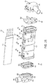
FIG. 1 is an exploded perspective view of an exemplary inflatable spa of the present disclosure, the inflatable spa including a plurality of tensioning structures; -
FIG. 2 is a top cross-sectional view of the inflatable spa ofFIG. 1 ; -
FIG. 3 is a side cross-sectional view of the inflatable spa ofFIG. 1 ; -
FIG. 4 is an elevational view of the tensioning structure ofFIG. 1 ; -
FIG. 5 is an exploded perspective view of the tensioning structure including a porous layer and two attachment layers; -
FIG. 6 is an exploded perspective view of the tensioning structure including a porous layer and an attachment layer; -
FIG. 7 is a top cross-sectional view of the tensioning structure coupled directly to the inflatable spa; -
FIG. 8 is a top cross-sectional view of the tensioning structure coupled indirectly to the inflatable spa via intermediate connecting layers; -
FIG. 9 is an exploded perspective view of an inflatable spa shown coupled to an exemplary control system of the present disclosure for supplying bubbles to the inflatable spa; -
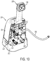
FIG. 10 is a perspective view of the control system ofFIG. 9 ; -
FIG. 11 is a perspective view of the control system ofFIG. 10 with an outer shell removed; -
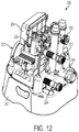
FIG. 12 is a perspective view of the control system ofFIG. 11 with a control panel assembly removed; -
FIG. 13 is an elevational view of the control system ofFIG. 12 ; -
FIG. 14 is an elevational cross-sectional view of the control system ofFIG. 11 ; -
FIG. 15 is an exploded perspective view of an air passageway of the control system ofFIG. 9 , the air passageway including an air pump, a first check valve, a drain valve, and a second check valve; -
FIG. 16 is a cross-sectional view of the air passageway ofFIG. 15 ; -
FIG. 17 is an exploded perspective view of the air pump, the first check valve, and the drain valve ofFIG. 15 ; -
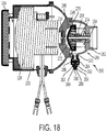
FIG. 18 is a cross-sectional view of the air pump, the first check valve, and the drain valve ofFIG. 17 ; -
FIG. 19 is an exploded perspective view of the second check valve ofFIG. 15 ; -
FIG. 20 is a cross-sectional view of the second check valve ofFIG. 19 ; -
FIG. 21 is an exploded perspective view of the control system ofFIG. 9 shown in a deflation mode; -
FIG. 22 is a cross-sectional view of the control system ofFIG. 21 ; -
FIG. 23 is a perspective view of the inflatable spa ofFIG. 9 ; -
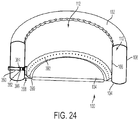
FIG. 24 is a perspective cross-sectional view of the inflatable spa ofFIG. 23 ; -
FIG. 25 is an exploded perspective view of an exemplary heating unit of the present disclosure; -
FIG. 26 is a cross-sectional view of the heating unit ofFIG. 25 ; -
FIG. 27 is a perspective view an exemplary control system of the present disclosure for supplying jetted water to an inflatable spa; -
FIG. 28 is a perspective view of the control system ofFIG. 27 with a base partially removed to show a drain assembly; -
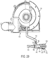
FIG. 29 is a side cross-sectional view of the control system and the drain assembly ofFIG. 28 ; -
FIG. 30 is a bottom plan view of the control system and the drain assembly ofFIG. 28 ; -
FIG. 31 is a schematic view of a water inlet system to the control system ofFIG. 27 including a water inlet pipe with a filtering cover; -
FIG. 32 is a perspective view of the water inlet pipe ofFIG. 31 ; -
FIG. 33 is a cross-sectional view of the water inlet pipe ofFIG. 32 ; -
FIG. 34 is a perspective view of the filtering cover ofFIG. 31 ; -
FIG. 35 is a cross-sectional view of the filtering cover ofFIG. 34 ; -
FIG. 36 is a schematic view of a water outlet system from the control system ofFIG. 27 including a water outlet pipe; -
FIG. 37 is a perspective view of the water outlet pipe ofFIG. 36 ; -
FIG. 38 is a cross-sectional view of the water outlet pipe ofFIG. 37 ; -
FIG. 39 is a perspective view of a spa with an external wall partially removed to show a jetted water pipe network including a plurality of spray nozzles; -
FIG. 40 is a perspective view of the jetted water pipe network ofFIG. 39 ; -
FIG. 41 is a top cross-sectional view of the spa ofFIG. 39 ; and -
FIG. 42 is a cross-sectional view of the spray nozzle ofFIG. 39 . - Corresponding reference characters indicate corresponding parts throughout the several views. The exemplifications set out herein illustrate exemplary embodiments of the invention and such exemplifications are not to be construed as limiting the scope of the invention in any manner.
- Referring initially to
FIGS. 1-3 , aninflatable spa 100 is shown including atop wall 102, abottom wall 104, aninternal wall 106, and anexternal wall 108. Thetop wall 102 is an annular wall and is connected to the top ends of both theinternal wall 106 and theexternal wall 108. Thebottom wall 104 is also an annular wall and is connected to the bottom ends of both theinternal wall 106 and theexternal wall 108. The diameter of theexternal wall 108 is larger than the diameter of theinternal wall 106. Thetop wall 102, thebottom wall 104, theinternal wall 106, and theexternal wall 108 ofspa 100 may be constructed of polyvinyl chloride (PVC), thermoplastic rubber (TPR), ethylene vinyl acetate (EVA), thermoplastic polyurethane elastomer (TPU), or other suitable materials. -
Spa 100 includes aninflatable air chamber 110 formed between thetop wall 102, thebottom wall 104, theinternal wall 106, and theexternal wall 108. Theair chamber 110 includes one or more suitable air vents (not shown) for inflating and deflating theair chamber 110. In certain embodiments, theair chamber 110 may be inflated to a relatively high pressure greater than about 0.8 psi. For example, theair chamber 110 may be inflated to a pressure of about 0.9 psi, 1.0 psi, 1.1 psi, 1.2 psi, 1.3 psi, 1.4 psi, 1.5 psi, 1.6 psi, or more. Such pressures may be about 1.5 or 2 times greater than pressures used to inflate traditional inflatable products. -
Spa 100 also includes awater cavity 112 formed by thebottom wall 104 and theinternal wall 106. One or more covers, such as a sealingcover 114 and adust cover 116 above the sealingcover 114, may be provided to cover thewater cavity 112 whenspa 100 is not in use, as shown inFIG. 9 . - Inside the
air chamber 110,spa 100 also includes a plurality ofinternal tensioning structures 120 that maintain the shape ofspa 100 when theair chamber 110 is pressurized. The tensioningstructures 120 may enhance the strength of thespa 100, allowing theair chamber 110 to withstand relatively high internal pressures, as discussed above, while also providing comfort to a user sitting on or inspa 100. - As shown in
FIGS. 1 and2 , the tensioningstructures 120 are arranged vertically and radially in theair chamber 110 in an annular array pattern. As shown inFIG. 3 , eachtensioning structure 120 may be coupled to theinternal wall 106 and theexternal wall 108, as discussed further below with reference toFIGS. 7 and 8 . Also, eachtensioning structure 120 may be spaced apart fromtop wall 102 and thebottom wall 104 to define anupper gap 122 relative to thetop wall 102 and alower gap 124 relative to thebottom wall 104. - Referring next to
FIGS. 4-6 , eachtensioning structure 120 may include a porous layer orsheet 130 and one or more attachment layers orsheets 132 attached (e.g., laminated) to theporous layer 130. In the illustrated embodiment ofFIG. 5 , theporous layer 130 is sandwiched between twoattachment layers 132, with the attachment layers 132 being attached to both theupper surface 160 and thelower surface 162 of theporous layer 130. In the illustrated embodiment ofFIG. 6 , theporous layer 130 is attached to asingle attachment layer 132, with thesingle attachment layer 132 being attached to either theupper surface 160 or thelower surface 162 of theporous layer 130. - Except for the
upper gap 122 and thelower gap 124 in thetensioning structure 120, thetensioning structure 120 may be generally rectangular in shape, as shown inFIG. 4 . In this embodiment, theporous layer 130 includes a generally rectangular outer perimeter 150 formed byedges 152a-d, and theattachment layer 132 includes a generally rectangular outer perimeter 154 formed byedges 156a-d. Theattachment layer 132 may span across the entireporous layer 130, as shown inFIG. 4 , such that the outer perimeter 154 of theattachment layer 132 generally overlaps the outer perimeter 150 of theporous layer 130. It is also within the scope of the present disclosure that theattachment layer 132 may span across a portion of theporous layer 130. - The
porous layer 130 may be formed from a plurality of ligaments orframe members 134 that define a plurality of holes orpores 136 therebetween, as shown inFIG. 4 . When theair chamber 110 is pressurized,frame members 134 may be placed in tension to help maintain the shape ofspa 100.Adjacent frame members 134 may be spaced apart at regular intervals to provide thetensioning structure 120 with a substantially constant tensile strength. - Each
pore 136 of theporous layer 130 may be enclosed or entirely surrounded by intersectingframe members 134 over a 360 degree range. A plurality ofpores 136 may be located entirely within the outer perimeter 154 of theattachment layer 132 to facilitate attachment to theattachment layer 132, as discussed further below. It is also within the scope of the present disclosure thatother pores 136 may be located outside of the outer perimeter 154 of theattachment layer 132. The size and shape of eachpore 136 may vary depending on the thickness and orientation of the surroundingframe members 134. Theporous layer 130 may also include a plurality ofopen spaces 158 that are partially surrounded byframe members 134 and partially exposed along the outer perimeter 150, for example. - In the illustrated embodiment of
FIG. 4 , theframe members 134 are arranged in a grid pattern, including a first set of spaced-apart andparallel frame members 138 and a second set of spaced-apart andparallel frame members 139. In this grid pattern, the first set offrame members 138 is transverse to the second set offrame members 139 such that the first set offrame members 138 intersects the second set offrame members 139. InFIG. 4 , the grid pattern is rotated by about 45 degrees from a horizontal axis to resemble a lattice, such that the first set offrame members 138 are angled upward from the horizontal axis (e.g., about +45 degrees from the horizontal axis), and the second set offrame members 139 are angled downward from the horizontal axis (e.g., about -45 degrees from the horizontal axis) and substantially perpendicular to the first set offrame members 138. Betweenadjacent frame members 134, evenly spaced, diamond-shapedpores 136 are formed inFIG. 4 .Adjacent pores 136 may also be angled upward and downward relative to the horizontal axis. - According to an exemplary embodiment of the present disclosure, the
porous layer 130 may be constructed of a mesh, cloth, or screen having interwoven strings, fibers, or wires asindividual frame members 134. As shown inFIG. 4 , eachframe member 134 may include a firstterminal end 170 located at an edge (e.g.,edge 152a) of theporous layer 130 and a secondterminal end 172 located at an opposing edge (e.g.,edge 152c) of theporous layer 130. - As discussed above, each
tensioning structure 120 may be coupled to theinternal wall 106 and theexternal wall 108 using suitable coupling techniques, such as high-frequency coupling, hot coupling (e.g., melting, welding), or adhering (e.g., gluing), for example. In the illustrated embodiment ofFIG. 7 , thetensioning structure 120 is directly coupled to theinternal wall 106 and theexternal wall 108 along aseam 142. In the illustrated embodiment ofFIG. 8 , thetensioning structure 120 is indirectly coupled to theinternal wall 106 and theexternal wall 108 using intermediate connectinglayers 140. More specifically, thetensioning structure 120 is coupled to the intermediate connectinglayers 140 via afirst seam 144, and the intermediate connectinglayers 140 are coupled to theinternal wall 106 and theexternal wall 108 via asecond seam 146. As shown inFIGS. 7 and 8 , theseams tensioning structure 120. Returning toFIG. 4 , theseams side edges tensioning structure 120 to attach thetensioning structure 120 to the adjacentinternal wall 106 and along the left-side edges tensioning structure 120 to attach thetensioning structure 120 to the adjacentexternal wall 108, for example. - According to an exemplary embodiment of the present disclosure, the
frame members 134 are oriented transverse (i.e., not parallel) to theseams FIG. 4 , theframe members 138 are angled side-to-side in the vertical direction. In this embodiment, as thevertical seams vertical seams tensioning structure 120, the vertical line will intersect at least onepore 136 oropen space 158 between theframe members 134. In other words, there is no vertical line that will pass entirely through thetensioning structure 120 along aframe member 134 without intersecting at least onepore 136 oropen space 158 adjacent to theframe member 134. InFIG. 4 , theframe members 138 are also oriented transverse to any horizontal line that is perpendicular to theseams frame members 138 are angled upward and downward in the horizontal direction. In this embodiment, as any horizontal line perpendicular to thevertical seams tensioning structure 120, the horizontal line will intersect at least onepore 136 oropen space 158 between theframe members 134. In other words, there is no horizontal line that will pass entirely through thetensioning structure 120 along aframe member 134 without intersecting at least onepore 136 oropen space 158 adjacent to theframe member 134. - To facilitate secure connections between the
tensioning structure 120, theinternal wall 106 ofspa 100, theexternal wall 108 ofspa 100, and the optional intermediate connectinglayers 140, the materials used to construct these adjacent layers may be the same or otherwise compatible. For example, if theinternal wall 106, theexternal wall 108, and the optional intermediate connectinglayers 140 are constructed of PVC, TPR, EVA, or TPU, at least a portion of the correspondingtensioning structure 120 may also be constructed of PVC, TPR, EVA, or TPU. In embodiments where the adjacent layers are melted using high-frequency radiation, for example, the compatible materials may have the same or similar melting points to ensure that the materials melt, blend together, and form secure connections. According to an exemplary embodiment of the present disclosure, at least theattachment layer 132 of thetensioning structure 120 may be constructed of a compatible material. Theporous layer 130 of thetensioning structure 120, by contrast, may be constructed of a different, potentially incompatible (e.g., higher melting), potentially stronger material, because thepores 136 in theporous layer 130 may accommodate bonding of adjacent compatible materials (e.g., one or more attachment layers 132, theinternal wall 106 ofspa 100, theexternal wall 108 ofspa 100, and/or the optional intermediate connecting layers 140) through thepores 136 in theporous layer 130. For example, theattachment layer 132 of thetensioning structure 120 may be constructed of a compatible material such as PVC, TPR, EVA, or TPU, whereas theporous layer 130 of thetensioning structure 120 may be constructed of a cloth or screen. - It is also within the scope of the present disclosure that
internal tensioning structures 120 may include a pair of plastic sheets connected together via a plurality of tensioning strands, such as strings or wires, as disclosed in U.S. Patent Application Publication No.US 2013/0230671 , the disclosure of which is expressly incorporated herein by reference in its entirety. - It is also within the scope of the present disclosure that the
tensioning structures 120 may be used in other inflatable products, such as inflatable mattresses and pools. - Referring next to
FIGS. 10-14 , afirst control system 200 is shown for use withspa 100.Control system 200 includes abase 202 and anouter shell 204 mounted tobase 202.Control system 200 also includes acontroller 206 and acontrol panel assembly 208 having a plurality ofbuttons 210, as shown inFIG. 11 . In use, when a user inputs commands usingbuttons 210,control panel assembly 208 sends appropriate signals tocontroller 206, andcontroller 206 controls the operation ofcontrol system 200. -
Control system 200 includes awater passageway 220 that extends between awater inlet pipe 222 fromspa 100 and a water outlet or returnpipe 224 tospa 100. Along thewater passageway 220,control system 200 includes a filter pump (not shown) that pumps and filters water fromspa 100 and aheating unit 226 that heats water fromspa 100 before returning the water tospa 100, as shown inFIG. 11 . It is also within the scope of the present disclosure thatcontrol system 200 may include a hard water treatment unit (not shown) and/or a salt water unit (not shown). The user may selectively activate and deactivate theseunits using buttons 210 on thecontrol panel assembly 208. It is also within the scope of the present disclosure that some units may activate and deactivate automatically based on the status of another unit. For example, whenever theheating unit 226 is activated, the filter pump may activate automatically to pump water through the warmedheating unit 226. As another example, whenever the filter pump is activated, the hard water treatment unit may activate automatically to treat the filtered water. - Referring next to
FIGS. 15 and16 ,control system 200 also includes anair passageway 230. Along theair passageway 230,control system 200 includes anair pump 232 having anair generating assembly 234 with asuction side 236 and apressurized discharge side 238. Thedischarge side 238 of theair pump 232 includes a delivery or way-makingcavity 246 having an arcuatevalve seat surface 248 around thedelivery cavity 246. On thesuction side 236 of theair pump 232, theair passageway 230 includes an air inlet pipe 240 (which may also be referred to herein as a deflation pipe) (FIG. 13 ). On thedischarge side 238 of theair pump 232, theair passageway 230 includes a first air outlet pipe 242 (which may also be referred to herein as an inflation pipe) and a second air outlet pipe 244 (which may also be referred to herein as an aeration pipe). - Between the
discharge side 238 of theair pump 232 andspa 100, theillustrative air passageway 230 includes afirst pipe portion 250 that communicates with thedischarge side 238 of theair pump 232, asecond pipe portion 252 that follows thefirst pipe portion 250, and athird pipe portion 254 that follows thesecond pipe portion 252 and communicates with theoutlet pipes second pipe portion 252 is illustratively positioned aboveshell 204 and above the water level ofspa 100, more specifically above thetop wall 102 ofspa 100, to protect theair pump 232 by resisting the backflow of water fromspa 100 to theair pump 232. - The
control panel assembly 208 may be elevated relative tospa 100 to allow a user inspa 100 to more easily accessbuttons 210 on thecontrol panel assembly 208. As shown inFIG. 15 , thecontrol panel assembly 208 may be mounted to thesecond pipe portion 252 at a location above thetop wall 102 ofspa 100. It is also within the scope of the present disclosure that thecontrol panel assembly 208 may be telescopically coupled to shell 204 via a lifting rod, for example, for movement between a stored position belowspa 100 and a use position abovespa 100. - As discussed above, the
air passageway 230 may extend abovespa 100 to prevent the backflow of water fromspa 100 to theair pump 232. To further prevent such backflow of water to theair pump 232, theillustrative air passageway 230 also includes afirst check valve 260, adrain valve 280, and asecond check valve 310. Thefirst check valve 260 and thesecond check valve 310 may function simultaneously to provide dual-protection to theair pump 232, so that if one check valve is out of order, the other check valve can do the work. As shown inFIG. 16 , thefirst check valve 260 is arranged between thedischarge side 238 ofair pump 232 and thefirst pipe portion 250. Thesecond check valve 310 is arranged along thethird pipe portion 254, more specifically below the firstair outlet pipe 242 of thethird pipe portion 254 and above the secondair outlet pipe 244 of thethird pipe portion 254. - The
first check valve 260 is shown inFIGS. 17 and18 . Thefirst check valve 260 includes afirst housing 262 that is coupled to theair pump 232 and thefirst pipe portion 250 and defines aninternal cavity 264. Thefirst check valve 260 also includes afirst valve core 266 having astem 268, ahead 270, and ahemispherical sealing piece 272 coupled to thehead 270. Thefirst check valve 260 further includes a firstelastic spring 274 that interacts with thefirst valve core 266, the firstelastic spring 274 being sleeved around thestem 268 of thefirst valve core 266 with one end positioned againsthead 270 and the other end positioned against thefirst housing 262. - In operation, the
first valve core 266 moves longitudinally through theinternal cavity 264 of thefirst housing 262 between a sealed or closed position and an open position. In the sealed position, the sealingpiece 272 of thefirst valve core 266 extends into thedelivery cavity 246 and seals against thevalve seat surface 248, as shown inFIG. 18 . In the open position, the sealingpiece 272 of thefirst valve core 266 moves out of thedelivery cavity 246 and separates from thevalve seat surface 248. - The
first housing 262 may also include adrain valve 280 coupled to adrain hole 282 from thefirst housing 262, as shown inFIGS. 17 and18 . Thedrain valve 280 includes anupper housing 284 having an uneven or wavy uppervalve seat surface 286 and alower housing 288 having a lowervalve seat surface 290. Theupper housing 284 and thelower housing 288 cooperate to define aninternal drain cavity 292 in fluid communication with thedrain hole 282. In certain embodiments, thedrain hole 282 from thefirst housing 262 may be internally threaded and theupper housing 284 may be externally threaded to screw into to thefirst housing 262. Thedrain valve 280 also includes adrain valve core 294 having astem 296, aflat head 298 having a clampingslot 300, and acircular sealing piece 302 positioned in theclamping slot 300. Thedrain valve 280 also includes anelastic spring 304 that interacts with thedrain valve core 294, theelastic spring 304 being sleeved around thestem 296 of thedrain valve core 294 with one end positioned againsthead 298 and the other end positioned against thelower housing 288. - In operation, the
drain valve core 294 moves longitudinally through theinternal drain cavity 292 between a sealed or closed position and an open position. In the sealed position, the sealingpiece 302 of thedrain valve core 294 is hermetically sealed against the lowervalve seat surface 290. In the open position, the sealingpiece 302 of thedrain valve core 294 moves away from the lowervalve seat surface 290 and theflat head 298 of thedrain valve core 294 moves toward the uneven uppervalve seat surface 286. - When the
air pump 232 is on, theair generating assembly 234 operates and directs pressurized air from thesuction side 236 of theair pump 232 to thedelivery cavity 246. Upon reaching thefirst check valve 260, the air drives thefirst valve core 266 through theinternal cavity 264 to the open position, in which thesealing piece 272 is separated from thevalve seat surface 248 and the firstelastic spring 274 is compressed. With thefirst check valve 260 in the open position, air from thedelivery cavity 246 enters thefirst housing 262 and flows out of theinternal cavity 264. At the same time, thedrain valve core 294 of thedrain valve 280 moves downward under the action of air pressure to the sealed position, in which thesealing piece 302 is sealed against the lowervalve seat surface 290 and theelastic spring 304 is compressed. When thedrain valve 280 is in the sealed position, theair pump 232 is able to operate normally. - When the
air pump 232 is stopped, air pressure in thefirst check valve 260 disappears, and the firstelastic spring 274 returns and drives thefirst valve core 266 to the sealed position, in which thesealing piece 272 is sealed against thevalve seat surface 248. With thefirst check valve 260 in the sealed position, water fromspa 100 is prevented from reaching theair pump 232. At the same time, air pressure disappears in thedrain valve 280, and theelastic spring 304 returns and drives thedrain valve core 294 upward to the open position, in which thesealing piece 302 of thedrain valve core 294 moves away from the lowervalve seat surface 290 and theflat head 298 of thedrain valve core 294 moves toward the uneven uppervalve seat surface 286. When thedrain valve 280 is in the open position, any fluid that may be present in thefirst housing 262 is able to drain from thedrain hole 282, through theinternal drain cavity 292, and to the outside environment. - The
second check valve 310 is shown inFIGS. 19 and20 . As discussed above, thesecond check valve 310 is arranged along thethird pipe portion 254. More specifically, thesecond check valve 310 is arranged between anupper section 312 and alower section 314 of thethird pipe portion 254, where theupper section 312 increases in diameter in a downward direction and thelower section 314 increases in diameter in the downward direction. - The
second check valve 310 includes asecond valve mount 320 having a circular locating ring 322 a hollow locating stem 324 located in the locatingring 322, and one ormore apertures 326 corresponding toapertures 328 in thelower section 314 for fastening thesecond valve mount 320 to thelower section 314 of thethird pipe portion 254, such as with screws (not shown). Thesecond check valve 310 also includes asecond valve core 330 having astem 332, ahead 334 with a lower stop platform orsurface 336, and ahemispherical sealing piece 338 coupled tohead 334. Thesecond check valve 310 further includes a secondelastic spring 340 that interacts with thesecond valve core 330, the secondelastic spring 340 being sleeved aroundstem 332 of thesecond valve core 330 with one end positioned against head 333 and the other end positioned against thesecond valve mount 320. - In operation, the
second valve core 330 moves longitudinally through the locatingstem 324 of thesecond valve mount 320 between a sealed or closed position and an open position. In the sealed position, the sealingpiece 338 of thesecond valve core 330 is hermetically sealed against theupper section 312 of thethird pipe portion 254, as shown inFIG. 20 . The sealingpiece 338 may produce line contact with theupper section 312 of thethird pipe portion 254 in the sealed position. In the open position, the sealingpiece 338 of thesecond valve core 330 moves away from theupper section 312 of thethird pipe portion 254 until thelower stop surface 336 ofhead 334 abuts the locatingstem 324 of thesecond valve mount 320. Because of the line contact produced between the sealingpiece 338 and theupper section 312 of thethird pipe portion 254 in the sealed position, the sealingpiece 338 may separate freely from theupper section 312 of thethird pipe portion 254 without an adhesion phenomenon, even if thesecond check valve 310 has not out of use for some time, thereby increasing the service life of thesecond check valve 310. - When there is no air or water present in the
third pipe portion 254, thesecond check valve 310 moves to the sealed position, in which thesealing piece 338 of thesecond valve core 330 is hermetically sealed against theupper section 312 of thethird pipe portion 254 under the action of the secondelastic spring 340. Because theupper section 312 of thethird pipe portion 254 narrows in an upward direction, the sealing between the sealingpiece 338 of thesecond valve core 330 and theupper section 312 of thethird pipe portion 254 becomes progressively tighter as the water pressure fromspa 100 increases. - When the
air pump 232 is on, the air reaches thesecond check valve 310 and drives thesecond valve core 330 downward through the locatingstem 324 of thesecond valve mount 320 to the open position, in which thesealing piece 338 is separated from theupper section 312 of thethird pipe portion 254 and the secondelastic spring 340 is compressed. With thesecond check valve 310 in the open position, air flows through the locatingstem 324 of thesecond valve mount 320 and tospa 100. -
Control system 200 may have at least three modes of operation, including: (1) an inflation mode, (2) a deflation mode, and (3) an aeration or bubble mode. Rather than having to buy multiple pieces of equipment to perform these individual functions, the user may rely oncontrol system 200 to perform these functions, which may save space and costs. The user may select the desired mode using thecontrol panel assembly 208. These modes of operation are described further below. - In the inflation mode,
control system 200 may direct air from thedischarge side 238 of theair pump 232, to theinflation pipe 242, and to theair chamber 110 ofspa 100 to inflatespa 100. The inflation mode may be achieved by removing a detachablesealing cover assembly 360 from theinflation pipe 242 to open theinflation pipe 242. The sealingcover assembly 360 illustratively includes a sealingplug 362, a cap or coverbody 364 that covers the sealingplug 362 and threadably couples to theinflation pipe 242, and asealing ring 366 positioned between the sealingplug 362 and theinflation pipe 242. The inflation mode may also involve coupling anextension tube 368 to theinflation pipe 242 to increase the length of theinflation pipe 242 for coupling to theair chamber 110 ofspa 100, as shown inFIG. 10 . The inflation mode may also involve covering or closing theaeration pipe 244. - In the deflation mode,
control system 200 may pull air from theair chamber 110 ofspa 100, through thedeflation pipe 240, and into thesuction side 236 of theair pump 232 to deflatespa 100, as shown inFIGS. 21 and22 . The deflation mode may involve coupling anextension tube 370 to thedeflation pipe 240 to increase the length of thedeflation pipe 240 for coupling to theair chamber 110 ofspa 100. In other modes of operation, thesuction side 236 of theair pump 232 may pull air from the surrounding atmosphere. - In the aeration or bubble mode,
control system 200 may direct air from thedischarge side 238 of theair pump 232, to theaeration pipe 244, and to thewater cavity 112 ofspa 100 to create massaging air bubbles inspa 100. The aeration mode may be achieved by covering theinflation pipe 242 with the sealingcover assembly 360 to close theinflation pipe 242 and opening theaeration pipe 244. As shown inFIGS. 23 and24 ,spa 100 may include anair transport pipe 380 that communicates with theaeration pipe 244 and extends through theexternal wall 108, through theair chamber 110, and through theinternal wall 106 toward thewater cavity 112. Theair transport pipe 380 may include aclapboard 382 having a mountinghole 384 and athird check valve 386 mounted in the mountinghole 384 to prevent the backflow of water from thewater cavity 112 ofspa 100.Spa 100 may also include anair delivery chamber 388 in communication with theair transport pipe 380. Theair delivery chamber 388 is illustratively formed by anannular wall 390 that is hermetically coupled to thebottom wall 104 ofspa 100 and includes a plurality of air delivery holes 392 to deliver massaging air bubbles from theair delivery chamber 388 into thewater cavity 112 ofspa 100. Although the illustrativeair delivery chamber 388 has an annular configuration, theair delivery chamber 388 may also have a multi-line configuration, for example. - An
exemplary heating unit 226 for use incontrol system 200 is shown inFIGS. 25 and26 . Theheating unit 226 includes aU-shaped housing 400, two sealingelements 402, twoend joints 404, each having awater cavity 406, and aheating element 408. - The
U-shaped housing 400 includes aU-shaped cavity 410 that runs longitudinally from end-to-end and anassembly groove 412 at the center of theU-shaped cavity 410 that also runs longitudinally from end-to-end. TheU-shaped cavity 410 and theassembly groove 412 may create a compact structure having good heating and water flow capacity. TheU-shaped housing 400 may also include a plurality of internal reinforcingribs 414, as shown inFIG. 26 , that are spaced apart along theU-shaped cavity 410 to increase the strength of theU-shaped housing 400. - The
heating element 408 may be a positive temperature coefficient (PTC) heating plate or another suitable heating element that safe, reliable, stable, and provides a high heating effect. Theheating element 408 may be disposed in theassembly groove 412 of theU-shaped housing 400 to heat the water flowing through the adjacentU-shaped cavity 410, which illustratively surrounds theheating element 408 on three of its four edges for substantial heating. Theheating element 408 may be held securely in place inside theassembly groove 412 by inserting a plurality ofbolts 420 throughreceptacles 422 in theU-shaped housing 400 and across theassembly groove 412 and then securingbolts 420 with nuts 424. - The two
end joints 404 are respectively disposed at both ends of theU-shaped housing 400. Thewater cavities 406 of the end joints 404 are arranged in fluid communication with theU-shaped cavity 410 of theU-shaped housing 400. On the mating surface 430 of each end joint 404 that faces inwardly toward with theU-shaped housing 400, the end joint 404 may include a firstU-shaped wall 432 that projects from the mating surface 430 to couple thecorresponding water cavity 406 to theU-shaped cavity 410 in theU-shaped housing 400 via the corresponding sealingelement 402, as discussed further below. One or both of the end joints 404 may include a thermostat 434 to measure the temperature of the water in theheating unit 226 before and/or after being heated by theheating element 408. - The two sealing
elements 402 are respectively disposed between theU-shaped housing 400 and the end joints 404. Each sealingelement 402 may include an inward mating surface 442 that faces inwardly to mate with theU-shaped housing 400, an outward mating surface 444 that faces outwardly to mate with the mating surface 430 of the corresponding end joint 404, and aU-shaped slot 446 that extends between the inward mating surface 442 and the outward mating surface 444. On the inward mating surface 442, each sealingelement 402 may include a secondU-shaped wall 448 that projects from the inward mating surface 442 and into theU-shaped cavity 410 in theU-shaped housing 400 to couple theU-shaped slot 446 to theU-shaped cavity 410 in a sealed manner. On the outward mating surface 444, eachU-shaped slot 446 may receive the firstU-shaped wall 432 of the corresponding end joint 404 in a sealed manner. - Returning to
FIGS. 10-14 ,controller 206 may ensure that the electric current of thecontrol system 200 stays below a predetermined limit, such as a standard household limit of 13 A to 16 A. In one embodiment,controller 206 may limit the power supply to one or more other units of thecontrol system 200 when theair pump 232 is activated in the aeration mode, andcontroller 206 may restore the power supply to the other units of thecontrol system 200 when theair pump 232 is deactivated. For example,controller 206 may automatically limit the power supply to theheating unit 226 to about 50% or less when theair pump 232 is activated in the aeration mode, andcontroller 206 may automatically restore the power supply to theheating unit 226 to 100% when theair pump 232 is deactivated. When necessary, the user may also be advised to deactivate one or more other units of thecontrol system 200, such as the salt water unit (not shown). - Referring next to
FIG. 27 , asecond control system 500 is shown for use withspa 100. Thesecond control system 500 may include various features in common with thefirst control system 200, except as described below. For example, thesecond control system 500 may include a controller similar to the above-describedcontroller 206 ofFIGS. 10-14 and a heating unit similar to the above-describedheating unit 226 ofFIGS. 25 and26 . Thesecond control system 500 may also include a hard water treatment unit (not shown) and/or a salt water unit (not shown). - The
illustrative control system 500 includes aninlet pipe 510 having a filteredwater inlet portion 512 and a jettedwater inlet portion 514. Although the filteredwater inlet portion 512 and the jettedwater inlet portion 514 are substantially parallel to one another and part of thesame inlet pipe 510, the filteredwater inlet portion 512 is independent of the jettedwater inlet portion 514 inFIG. 27 . Combining the filteredwater inlet portion 512 and the jettedwater inlet portion 514 in thesame inlet pipe 510 may decrease the number of pipes and holes required inspa 100, decrease the size and cost of thecontrol system 500, and simplify assembly of thecontrol system 500. - The
control system 500 further includes anoutlet pipe 520 having a filteredwater outlet portion 522 and a jettedwater outlet portion 524. Although the filteredwater outlet portion 522 and the jettedwater outlet portion 524 are collinear with one another and part of thesame outlet pipe 520, the filteredwater outlet portion 522 is independent of the jettedwater outlet portion 524 inFIG. 27 . As discussed above with respect to theinlet pipe 510, combining the filteredwater outlet portion 522 and the jettedwater outlet portion 524 in thesame outlet pipe 520 may decrease the number of pipes and holes required inspa 100, decrease the size and cost of thecontrol system 500, and simplify assembly of thecontrol system 500. - The
control system 500 still further includes a filteredwater pump 532 and a jettedwater pump 534. In operation, the filteredwater pump 532 directs water along a filtered water passageway from the filteredwater inlet portion 512 to the filteredwater outlet portion 522. The jettedwater pump 534 directs water along a jetted water passageway from the jettedwater inlet portion 514 to the jettedwater outlet portion 524. - The
control system 500 still further includes adrain assembly 540 including a filteredwater drain passageway 542 from the filtered water passageway, a jettedwater drain passageway 544 from the jetted water passageway, adrain valve body 546 located below the filtered water passageway and the jetted water passageway, and adrain valve plug 548 having afirst sealing element 550 and asecond sealing element 552. - The
drain valve body 546 includes afirst inlet 560 in fluid communication with the filteredwater drain passageway 542, asecond inlet 562 in fluid communication with the jettedwater drain passageway 544, and a combinedoutlet 564 that discharges water from the filteredwater drain passageway 542 and the jettedwater drain passageway 544. Thedrain valve body 546 also includes afirst portion 570 that defines the first andsecond inlets outlet 564. In the illustrated embodiment ofFIG. 29 , thefirst portion 570 of thedrain valve body 546 is internally threaded. - The
drain valve plug 548 extends through theoutlet 564 in thesecond portion 572 of thedrain valve body 546 and into thefirst portion 570 of thedrain valve body 546. Thedrain valve plug 548 is movably coupled to thedrain valve body 546. In the illustrated embodiment ofFIG. 29 , thedrain valve plug 548 is externally threaded for threaded, rotatable engagement with thefirst portion 570 of thedrain valve body 546. - The
first sealing element 550 is coupled to thedrain valve plug 548 and is configured to selectively open or close thefirst inlet 560 from the filteredwater drain passageway 542. As shown inFIG. 29 , thefirst sealing element 550 faces thefirst inlet 560 from the base of thedrain valve plug 548. - The
second sealing element 552 is coupled to thedrain valve plug 548 and is configured to selectively open or close thesecond inlet 562 from the jettedwater drain passageway 544. As shown inFIG. 29 , thesecond sealing element 552 is positioned between thedrain valve plug 548 and thedrain valve body 546. Thesecond sealing element 552 is tightly fit with thefirst portion 570 of thedrain valve body 546 and is loosely fit with thesecond portion 572 of thedrain valve body 546. - When the
control system 500 operates normally, thedrain valve plug 548 may be threaded into thedrain valve body 546. Thefirst sealing element 550 is pressed against thefirst inlet 560 to close the filteredwater drain passageway 542. Thesecond sealing element 552 is pressed against thefirst portion 570 of thedrain valve body 546 to also close the jettedwater drain passageway 544. - When the
control system 500 does not operate, thedrain valve plug 548 may be threaded away from thedrain valve body 546. Thefirst sealing element 550 is separated from thefirst inlet 560 to open the filteredwater drain passageway 542 to theoutlet 564 around thedrain valve plug 548. Thesecond sealing element 552 is separated from thefirst portion 570 of thedrain valve body 546 and moved into thesecond portion 572 of thedrain valve body 546 to open the jettedwater drain passageway 544 to theoutlet 564 around the looseneddrain valve plug 548. The ability to drain thecontrol system 500 by operating a singledrain valve plug 548 provides convenience, increased life, and improved serviceability. - Referring next to
FIGS. 31-33 ,spa 100 includes aninlet pipe 600 that extends from thewater cavity 112, through afirst opening 602 in theinternal wall 106, through theair chamber 110, and through afirst opening 604 in theexternal wall 108 to direct water from thewater cavity 112 ofspa 100 to theinlet pipe 510 of thecontrol system 500. Theillustrative inlet pipe 600 includes a filteredwater inlet portion 612 having afirst end 614 located at theinternal wall 106 in fluid communication with thewater cavity 112 and asecond end 616 located at theexternal wall 108 in fluid communication with the filteredwater inlet portion 512 of thecontrol system 500. Theillustrative inlet pipe 600 also includes a jettedwater inlet portion 622 having afirst end 624 located at theinternal wall 106 in fluid communication with thewater cavity 112 and asecond end 626 located at theexternal wall 108 in fluid communication with the jettedwater inlet portion 514 of thecontrol system 500. - Like the filtered
water inlet portion 512 and the jettedwater inlet portion 514 of theinlet pipe 510 associated with thecontrol system 500, the filteredwater inlet portion 612 and the jettedwater inlet portion 622 of theinlet pipe 600 associated withspa 100 may be independent and parallel to one another, with a separatingwall 630 disposed therebetween. In cross-section, the separatingwall 630 may be circular in shape, arcuate in shape, rectangular in shape, or wavy in shape, for example. According to an exemplary embodiment of the present disclosure, the filteredwater inlet portion 612 is smaller in diameter than the jettedwater inlet portion 622 to ensure that the water pressure of the jetted water passageway is higher than that of the filtered water passageway. - The
inlet pipe 600 further includes afiltering cover 640. Thecover 640 includes afirst portion 642 in fluid communication with thefirst end 614 of the filteredwater inlet portion 612 of theinlet pipe 600, and asecond portion 644 in fluid communication with thefirst end 624 of the jettedwater inlet portion 622 of theinlet pipe 600, as shown inFIG. 33 . Like the filteredwater inlet portion 612 and the jettedwater inlet portion 622 of theinlet pipe 600, the correspondingfirst portion 642 andsecond portion 644 of thecover 640 may be independent and parallel to one another, and thefirst portion 642 may be smaller than thesecond portion 644. Cover 640 may be positioned at thefirst opening 602 in theinternal wall 106 to interface with thewater cavity 112 ofspa 100, as shown inFIG. 31 . - Cover 640 is shown in more detail in
FIGS. 34 and 35 . Afirst filter screen 646 is shown covering thefirst portion 642 and asecond filter screen 648 is shown covering thesecond portion 644. Thefirst filter screen 646 and thesecond filter screen 648 may be a unitary piece formed during a single forming step, which may decrease the size and cost ofcover 640 and simplify assembly ofcover 640. Thefirst filter screen 646 may be externally threaded for convenient coupling to other pipes, if applicable. - Referring next to
FIGS. 36-38 ,spa 100 includes anoutlet pipe 700 that extends from theoutlet pipe 520 of thecontrol system 500 to thewater cavity 112 ofspa 100 to return water tospa 100. Theillustrative outlet pipe 700 includes a filteredwater outlet portion 712 in fluid communication with the filteredwater outlet portion 522 of thecontrol system 500 and a jettedwater outlet portion 714 in fluid communication with the jettedwater outlet portion 524 of thecontrol system 500. - The
outlet pipe 700 includes amain body 720 and adiversion body 722 connected together via anintermediate connection body 724. Thediversion body 722 is illustratively perpendicular to themain body 720. The filteredwater outlet portion 712 extends through themain body 720. As shown inFIG. 36 , the filteredwater outlet portion 712 extends from afirst end 730 of themain body 720 located at theexternal wall 108 ofspa 100 to asecond end 732 of themain body 720 located at theinternal wall 106 ofspa 100 and above thediversion body 722. The jettedwater outlet portion 714 extends initially through themain body 720, then through theconnection body 724, and then through thediversion body 722 for distribution aroundspa 100. As shown inFIG. 36 , jettedwater outlet portion 714 extends from afirst end 734 of themain body 720 located at theexternal wall 108 ofspa 100 to two second ends oroutlets 736 located on either side of themain body 720. - Like the filtered
water outlet portion 522 and the jettedwater outlet portion 524 of theoutlet pipe 520 associated with thecontrol system 500, the filteredwater outlet portion 712 and the jettedwater outlet portion 714 of theoutlet pipe 700 associated withspa 100 may be independent and collinear with one another, at least initially, with a separatingwall 740 disposed therebetween. As shown inFIG. 38 , the separatingwall 740 extends through themain body 720 to separate the filteredwater outlet portion 712 from the jettedwater outlet portion 714 in themain body 720. In cross-section, the separatingwall 740 may be circular in shape, arcuate in shape, rectangular in shape, or wavy in shape, for example. According to an exemplary embodiment of the present disclosure, the filteredwater outlet portion 712 is smaller in diameter than the jettedwater outlet portion 714 to ensure that the water pressure of the jetted water passageway is higher than that of the filtered water passageway. - The
internal wall 106 ofspa 100 may define one or morefiltered water openings 750 for delivering filtered water to thewater cavity 112 and one or more jettedwater openings 752 for delivering jetted water to thewater cavity 112. In the illustrated embodiment ofFIG. 39 , theinternal wall 106 ofspa 100 includes one filteredwater opening 750 and several jettedwater openings 752 spaced annularly aboutspa 100. - Referring next to
FIGS. 39-42 ,spa 100 may include a jettedwater pipe network 760 in fluid communication with theoutlet pipe 700 to deliver jetted water to thewater cavity 112 ofspa 100. Theoutlet pipe 700 and the jettedwater pipe network 760 may be substantially contained or concealed within theair chamber 110 ofspa 100 to enhance the appearance ofspa 100, to protect theoutlet pipe 700 and the jettedwater pipe network 760 from the surrounding environment, to simplify assembly, disassembly, storage, and transport ofspa 100, and to reduce leakage fromspa 100. - The jetted
water pipe network 760 includes a plurality ofspray nozzles 762 that extend through the jettedwater openings 752 in theinternal wall 106 ofspa 100. As shown inFIG. 42 , eachspray nozzle 762 may include afirst segment 764 having a small internal diameter and asecond segment 766 having a large internal diameter in fluid communication with thefirst segment 764. Eachspray nozzle 762 may also include anair hole 768 into thesecond segment 766 at a location near thefirst segment 764. The diameter of theair hole 768 may be less than or equal to 0.8 mm, for example, to prevent water from leaking through theair hole 768. - The jetted
water pipe network 760 also includes a flexible connecting pipe 770 (e.g., a hose) betweenadjacent spray nozzles 762. The flexible nature of the connectingpipe 770 may allow the deflatedspa 100 to be folded for storage and/or transport. As shown inFIG. 40 , the flexible connectingpipe 770 of the jettedwater pipe network 760 extends annularly aroundspa 100 from bothoutlets 736 of theoutlet pipe 700. - The jetted
water pipe network 760 further includes a plurality of flexible sealingsleeves 772 to couple eachspray nozzle 762 to theinternal wall 106 ofspa 100 in a sealed manner to prevent air and water leakage inspa 100 and to prolong the useful life ofspa 100. Theinternal wall 106 ofspa 100 may be sandwiched between each sealingsleeve 772 and the correspondingspray nozzle 762 in a sealed manner, as shown inFIG. 41 . Each sealingsleeve 772 may have a stepped configuration including asmall stem portion 774 and alarge head portion 776 that forms aflange 778 around sealingsleeve 772. Thesmall stem portion 774 of each sealingsleeve 772 may be coupled internally or externally to the correspondingspray nozzle 762 using suitable coupling techniques, such as high-frequency coupling, hot coupling (e.g., melting or injection molding), or adhering (e.g., gluing). Theflange 778 on thelarge head portion 776 of each sealingsleeve 772 may be coupled to theinternal wall 106 ofspa 100 also suitable coupling techniques. According to an exemplary embodiment of the present disclosure, the material used to construct the sealingsleeves 772 may be the same as the material used to construct theinternal wall 106 ofspa 100, such as PVC, TPR, EVA, or TPU, for example. Such materials may be capable of being melted to seal the sealingsleeve 772 to its adjacent components and may be capable of undergoing thermal expansion without cracking. - The jetted
water pipe network 760 further includes anair transport pipe 780. Theair transport pipe 780 may be similar to the above-describedair transport pipe 380 ofFIGS. 23 and24 . In the illustrated embodiment ofFIGS. 39-40 , theair transport pipe 780 extends through theexternal wall 108, through theair chamber 110, and through theinternal wall 106 ofspa 100. Additional sealingsleeves 772 may be used to couple the air transport pipe to theexternal wall 108 and/or theinternal wall 106 ofspa 100 in a sealed manner. - The
air transport pipe 780 may direct air directly into thewater cavity 112 ofspa 100. Theair transport pipe 780 may also direct air indirectly into thewater cavity 112 ofspa 100 via thespray nozzles 762. In the illustrated embodiment ofFIGS. 39-40 , theair transport pipe 780 pulls air from the surrounding atmosphere, directs the air through an annular and flexible connectingpipe 782, and injects the air into theair hole 768 of eachspray nozzle 762 under the suction force of the water flowing through thespray nozzle 762. The air from theair transport pipe 780 mixes with the water in thespray nozzle 762 to spray jetted water into thewater cavity 112 ofspa 100. The flexible nature of the connectingpipe 782 may allow the deflatedspa 100 to be folded for storage and/or transport. - It is also within the scope of the present disclosure that the
air transport pipe 780 may communicate with an air pump (e.g.,air pump 232 ofFIGS. 15-18 ), as discussed above in the "Bubble Embodiment" section. In this embodiment, theair transport pipe 780 may also deliver massaging air bubbles tospa 100. - Returning to
FIG. 27 , the controller (not shown) of thecontrol system 500 may ensure that the electric current of thecontrol system 500 stays below a predetermined limit, such as a standard household limit of 13 A to 16 A. In one embodiment, the controller may limit the power supply to one or more other units of thecontrol system 500 when the jettedwater pump 534 is activated, and the controller may restore the power supply to the other units of the control system when the jettedwater pump 534 is deactivated. For example, the controller may automatically limit the power supply to the heating unit (not shown) to about 50% or less when the jettedwater pump 534 is activated, and the controller may automatically restore the power supply to the heating unit to 100% when the jettedwater pump 534 is deactivated. The controller may further limit the power supply to the heating unit to 0% when both the jettedwater pump 534 and an additional air pump are activated. - While this invention has been described as having exemplary designs, the present invention can be further modified within the spirit and scope of this disclosure. This application is therefore intended to cover any variations, uses, or adaptations of the invention using its general principles. Further, this application is intended to cover such departures from the present disclosure as come within known or customary practice in the art to which this invention pertains and which fall within the limits of the appended claims.
- Features of preferred embodiments of the invention in its various aspects are set out in the following numbered clauses:
- 1. An inflatable product comprising:
- a first wall;
- a second wall;
- an inflatable air chamber defined by the first wall and the second wall; and
- a plurality of tensioning structures located in the air chamber and coupled to the first wall and the second wall, each tensioning structure including:
- at least one attachment sheet having an outer perimeter; and
- a porous sheet coupled to the at least one attachment sheet, the porous sheet including a plurality of enclosed pores located entirely within the outer perimeter of the at least one attachment sheet.
- 2. The inflatable product of clause 1, wherein the porous sheet includes a plurality of frame members that intersect to define the plurality of enclosed pores.
- 3. The inflatable product of clause 2, wherein the plurality of frame members of the porous sheet are interwoven.
- 4. The inflatable product of clause 2, wherein the plurality of frame members of the porous sheet are arranged in a grid pattern.
- 5. The inflatable product of clause 2, wherein the porous sheet includes a plurality of open spaces that are partially surrounded by the frame members.
- 6. The inflatable product of clause 1, wherein the at least one attachment sheet has a lower melting point than the porous sheet.
- 7. The inflatable product of clause 1, wherein the at least one attachment sheet, the first wall, and the second wall have similar melting points.
- 8. The inflatable product of clause 1, wherein the porous sheet includes a second plurality of enclosed pores located beyond the outer perimeter of the at least one attachment sheet.
- 9. The inflatable product of clause 1, wherein the porous sheet has an outer perimeter that substantially overlaps the outer perimeter of the at least one attachment sheet.
- 10. The inflatable product of clause 1, wherein the product is a spa, the first wall is an internal wall of the spa, and the second wall is an external wall of the spa, the spa further comprising a bottom wall that cooperates with the internal wall to define a water cavity.
- 11. The inflatable product of clause 1, wherein the product is a spa with a water cavity, the product further comprising a heating unit in fluid communication with the water cavity, the heating unit including a heating element and a U-shaped water cavity around the heating element.
- 12. The inflatable product of clause 11, further comprising a control system with a controller that maintains a current of the control system below a predetermined level by limiting a power supply to the heating unit.
- 13. An inflatable product comprising:
- a first wall;
- a second wall;
- an inflatable air chamber defined by the first wall and the second wall; and
- a plurality of tensioning structures located in the air chamber, each tensioning structure being coupled to the first wall along a first seam that extends along a first line and to the second wall along a second seam that extends along a second line, each tensioning structure including a porous sheet with a plurality of pores, wherein any line parallel to the first line intersects the plurality of pores in the porous sheet.
- 14. The inflatable product of clause 13, wherein the porous sheet includes a plurality of frame members that cooperate to define the plurality of pores, wherein the plurality of frame members are oriented transverse to the first line.
- 15. The inflatable product of clause 14, wherein the plurality of frame members are oriented transverse to a third line that is perpendicular to the first line.
- 16. The inflatable product of clause 13, wherein the first line is parallel to the second line.
- 17. An inflatable spa comprising:
- a top wall;
- a bottom wall;
- an internal wall;
- an external wall;
- an inflatable air chamber defined by the top wall, the bottom wall, the internal wall, and the external wall;
- a water cavity defined by the bottom wall and the internal wall; and
- a control system including an air pump operable in:
- an inflation mode that supplies air to the air chamber to inflate the air chamber;
- a deflation mode that removes air from the air chamber to deflate the air chamber; and
- an aeration mode that supplies air to the water cavity to aerate the water cavity.
- 18. The inflatable spa of clause 17, further comprising an air passageway between the air pump and the spa that extends above the water cavity of the spa.
- 19. The inflatable spa of clause 18, wherein the control system further includes a control panel assembly that receives a user input, wherein the control panel assembly is mounted to the air passageway at a location above the water cavity of the spa.
- 20. The inflatable spa of clause 18, wherein the air passageway includes a first check valve and a second check valve positioned in series to prevent a backflow of water from the water cavity of the spa to the air pump.
- 21. The inflatable spa of clause 20, wherein at least one of the first check valve and the second check valve becomes progressively tighter as water pressure from the water cavity of the spa increases.
- 22. An inflatable spa comprising:
- a top wall;
- a bottom wall;
- an internal wall;
- an external wall;
- an inflatable air chamber defined by the top wall, the bottom wall, the internal wall, and the external wall;
- a water cavity defined by the bottom wall and the internal wall; and
- a jetted water pipe network that delivers jetted water to the water cavity, wherein the jetted water pipe network is substantially concealed within the inflatable air chamber.
- 23. The inflatable spa of clause 22, further comprising a control system and a single water inlet pipe between the water cavity and the control system, wherein the water inlet pipe includes a filtered water inlet portion and a jetted water inlet portion.
- 24. The inflatable spa of clause 23, wherein the control system includes a drain assembly having:
- a filtered water drain passageway in fluid communication with the filtered water inlet portion of the water inlet pipe;
- a jetted water drain passageway in fluid communication with the jetted water inlet portion of the water inlet pipe; and
- an outlet in fluid communication with both the filtered water drain passageway and the jetted water drain passageway.
- 25. The inflatable spa of clause 23, further comprising a filtering cover that covers both the filtered water inlet portion and the jetted water inlet portion of the water inlet pipe.
- 26. The inflatable spa of clause 22, wherein the jetted water pipe network includes a plurality of spray nozzles, a first connecting pipe that delivers water to the plurality of spray nozzles, and a second connecting pipe that delivers air to the plurality of spray nozzles, wherein the plurality of spray nozzles, the first connecting pipe, and the second connecting pipe are substantially concealed within the inflatable air chamber.
- 27. The inflatable spa of clause 26, wherein the first and second connecting pipes are flexible.
- 28. The inflatable spa of clause 26, wherein the plurality of spray nozzles are spaced apart annularly about the internal wall of the spa.
- 29. A method of erecting an inflatable spa having an inflatable air chamber and a water cavity, the method comprising:
inflating the air chamber of the inflatable spa to a pressure greater than about 0.8 psi. - 30. The method of clause 29, wherein the pressure is about 1.5 psi.
- 31. A method of manufacturing an inflatable product having an air chamber defined by a plurality of walls, the method comprising:
- providing a porous sheet of a first material, at least a portion of the first material surrounding a plurality of pores in the porous sheet;
- placing the porous sheet between a second sheet of a second material and a third sheet of a third material, the second material and the third material covering the portion of the first material that surrounds the plurality of pores in the porous sheet;
- attaching the second sheet to the third sheet; and
- placing the porous sheet in the air chamber of the inflatable product.
- 32. The method of clause 31, wherein the second sheet comprises an attachment layer located between one of the plurality of walls of the inflatable product and the porous layer.
- 33. The method of clause 31, wherein the second sheet comprises one of the plurality of walls of the inflatable product.
- 34. The method of clause 31, wherein the attaching step comprises attaching the second material of the second sheet to the third material of the third sheet through the plurality of pores in the porous sheet.
- 35. The method of clause 31, wherein the attaching step comprises melting the second material of the second sheet and the third material of the third sheet.
- 36. The method of clause 31, wherein the second material of the second sheet is the same as the third material of the third sheet.
Claims (15)
- An inflatable spa (100) comprising:a top wall (102);a bottom wall (104);an internal wall (106);an external wall (108);an inflatable air chamber (110) defined by the top wall (102), the bottom wall (104), the internal wall (106), and the external wall (108);a water cavity (112) defined by the bottom wall (104) and the internal wall (106);a control system (500);a water inlet pipe (600) that directs water from the water cavity (112) to the control system (500);a water outlet pipe (700) that returns water from the control system (500);a flexible water connecting pipe (770) extending from the water outlet pipe (700); anda plurality of spray nozzles (762), each spray nozzle (762) extending through the internal wall (106) and having an air hole (768) to deliver jetted water to the water cavity (112);wherein the flexible water connecting pipe (770) extends between adjacent spray nozzles (762) and is concealed within the inflatable air chamber (110).
- The spa (100) of claim 1, wherein the outlet pipe (700) includes:a main body (720) having a first end (730) located at the external wall (108) and a second end (732) located at the internal wall (106); anda diversion body (722) perpendicular to the main body (720).
- The spa (100) of claim 2, wherein the diversion body (722) includes two outlets (736) located on either side of the main body (720).
- The spa (100) of claim 2 or 3, wherein the outlet pipe (700) includes:a filtered water outlet portion (712) extending from the first end (730) of the main body (720) to the second end (732) of the main body (720); anda jetted water outlet portion (714) extending through the diversion body (722) for distribution around the spa (100).
- The spa (100) of claim 4, wherein the jetted water outlet portion (714) extends from a first end (734) of the main body (720) located at the external wall (108) to two outlets (736) of the diversion body (722).
- The spa (100) of claim 4 or 5, wherein the filtered water outlet portion (712) is smaller in diameter than the jetted water outlet portion (714).
- The spa (100) of any preceding claim, wherein the control system (500) includes:a filtered water pump (532); anda jetted water pump (534).
- The spa (100) of any preceding claim, further comprising an air transport pipe (780) that pulls air from the surrounding atmosphere, wherein air from the air transport pipe (780) mixes with the water in the spray nozzles (762).
- The spa (100) of any preceding claim, further comprising a flexible air connecting pipe (782) that injects air into the air hole (768) under a suction force of the water flowing through the spray nozzle (762), wherein the flexible air connecting pipe (782) is concealed within the inflatable air chamber (110).
- The inflatable spa (100) of any preceding claim, wherein the spray nozzle (762) includes a first segment (764) having a small internal diameter and a second segment (766) having a large internal diameter in fluid communication with the first segment (764), the air hole (768) extending into the second segment (766).
- The inflatable spa (100) of any preceding claim, further comprising a plurality of tensioning structures (120) arranged in the inflatable air chamber (110), each tensioning structure (120) coupled to the internal wall (106) and the external wall (108) and spaced apart from top wall (102) to define an upper gap (122) and from the bottom wall (104) to define a lower gap (124).
- The inflatable spa (100) of claim 11, wherein each tensioning structure (120) comprises one or more attachment layers (132) laminated to a porous layer (130).
- The inflatable spa (100) of claim 12, wherein the porous layer (130) comprises a plurality of frame members (134) in the form of interwoven strings, each frame member (134) having a first terminal end (170) located at a first edge (152a) of the porous layer (130) and a second terminal end (172) located at an opposing edge (152c) of the porous layer (130).
- The inflatable spa (100) of any preceding claim, wherein the control system (500) includes a heating unit (226), a hard water treatment unit, and/or a salt water unit.
- The inflatable spa (100) of any preceding claim, wherein the internal wall (106) is sandwiched between a sealing sleeve (772) and the corresponding spray nozzle (762).
Applications Claiming Priority (15)
| Application Number | Priority Date | Filing Date | Title |
|---|---|---|---|
| CN201320428910.0U CN203421809U (en) | 2013-07-18 | 2013-07-18 | Heating system for pool |
| CN201320745798 | 2013-11-21 | ||
| CN201320745863.2U CN203627900U (en) | 2013-11-21 | 2013-11-21 | Water escape valve structure and inflatable pool control box using same |
| CN201320745887.8U CN203583941U (en) | 2013-11-21 | 2013-11-21 | Water outlet pipe structure, inflatable water pool with water outlet pipe structure, and control cabinet |
| CN201320746974.5U CN203583942U (en) | 2013-11-21 | 2013-11-21 | Water inlet pipe structure and inflatable pool and control cabinet using structure |
| CN201320796506.9U CN203583938U (en) | 2013-12-05 | 2013-12-05 | Inflatable pool |
| CN201320892855.0U CN203640334U (en) | 2013-12-30 | 2013-12-30 | Filter cover structure and inflatable pond using filter cover structure |
| CN201320888639.9U CN203640339U (en) | 2013-12-30 | 2013-12-30 | Inflation pipe structure of inflatable pool capable of preventing water from flowing reversely |
| CN201320888403.5U CN203634453U (en) | 2013-12-30 | 2013-12-30 | Massage pool system |
| CN201410017358.5A CN103912147B (en) | 2013-11-21 | 2014-01-15 | A kind of side spray Inflation water pond facilitating folding |
| CN201420023673.4U CN203684742U (en) | 2013-11-21 | 2014-01-15 | Side-spraying inflation pool convenient to fold |
| CN201420050705.XU CN203687330U (en) | 2014-01-26 | 2014-01-26 | Heating inner container structure |
| CN201420375437.9U CN203924786U (en) | 2014-07-08 | 2014-07-08 | A kind of getter device of Inflation water pond |
| EP14826258.7A EP3021721B1 (en) | 2013-07-18 | 2014-07-18 | Inflatable spa |
| PCT/US2014/047252 WO2015010058A2 (en) | 2013-07-18 | 2014-07-18 | Inflatable spa |
Related Parent Applications (2)
| Application Number | Title | Priority Date | Filing Date |
|---|---|---|---|
| EP14826258.7A Division-Into EP3021721B1 (en) | 2013-07-18 | 2014-07-18 | Inflatable spa |
| EP14826258.7A Division EP3021721B1 (en) | 2013-07-18 | 2014-07-18 | Inflatable spa |
Publications (2)
| Publication Number | Publication Date |
|---|---|
| EP3739148A1 true EP3739148A1 (en) | 2020-11-18 |
| EP3739148B1 EP3739148B1 (en) | 2023-09-06 |
Family
ID=52346851
Family Applications (3)
| Application Number | Title | Priority Date | Filing Date |
|---|---|---|---|
| EP17170443.0A Revoked EP3225764B1 (en) | 2013-07-18 | 2014-07-18 | Inflatable spa |
| EP14826258.7A Active EP3021721B1 (en) | 2013-07-18 | 2014-07-18 | Inflatable spa |
| EP20182819.1A Active EP3739148B1 (en) | 2013-07-18 | 2014-07-18 | Inflatable spa |
Family Applications Before (2)
| Application Number | Title | Priority Date | Filing Date |
|---|---|---|---|
| EP17170443.0A Revoked EP3225764B1 (en) | 2013-07-18 | 2014-07-18 | Inflatable spa |
| EP14826258.7A Active EP3021721B1 (en) | 2013-07-18 | 2014-07-18 | Inflatable spa |
Country Status (5)
| Country | Link |
|---|---|
| US (7) | US9254240B2 (en) |
| EP (3) | EP3225764B1 (en) |
| ES (3) | ES2964562T3 (en) |
| PL (1) | PL3021721T3 (en) |
| WO (1) | WO2015010058A2 (en) |
Families Citing this family (40)
| Publication number | Priority date | Publication date | Assignee | Title |
|---|---|---|---|---|
| AR082877A4 (en) * | 2011-09-01 | 2013-01-16 | Eduardo Alberto Mussa | CONTINUOUS INFLATABLE SLEEVE FOR CANVAS PILETS |
| ES2644232T3 (en) | 2012-03-02 | 2017-11-28 | Intex Marketing Ltd. | Method to produce a tension structure that can be used with inflatable devices |
| ES2964562T3 (en) | 2013-07-18 | 2024-04-08 | Intex Marketing Ltd | Inflatable hydrotherapy bath |
| US20220325546A1 (en) * | 2013-07-18 | 2022-10-13 | Intex Marketing Ltd. | Inflatable spa |
| CN103600502A (en) | 2013-11-25 | 2014-02-26 | 明达实业(厦门)有限公司 | Melting technology of inflatable products |
| USD741436S1 (en) * | 2014-03-03 | 2015-10-20 | Intex Recreation Corp. | Oval inflatable spa |
| MX2017000108A (en) | 2015-05-12 | 2017-06-30 | Intex Marketing Ltd | Water spraying device for above ground pool. |
| US10660819B2 (en) * | 2015-07-16 | 2020-05-26 | Bestway Inflatables & Material Corp. | Pool pump |
| CN204850582U (en) | 2015-08-26 | 2015-12-09 | 明达实业(厦门)有限公司 | Pond shower nozzle and pond of aerifing of using this shower nozzle |
| US9896854B2 (en) | 2015-10-10 | 2018-02-20 | Bestway Inflatables & Material Corp. | Pool apparatus |
| US10132095B2 (en) * | 2015-10-10 | 2018-11-20 | Bestway Inflatables & Material Corp. | Pool apparatus |
| USD791334S1 (en) | 2016-01-05 | 2017-07-04 | Bestway Inflatable & Material Corp. | Boat shaped pool for spa |
| WO2017148525A1 (en) * | 2016-03-03 | 2017-09-08 | Hermann Peitz | Massage device |
| CN205840412U (en) * | 2016-04-28 | 2016-12-28 | 上海荣威塑胶工业有限公司 | Inflatable structure for portable SPA pond |
| CN107338976A (en) | 2017-01-11 | 2017-11-10 | 明达实业(厦门)有限公司 | Endless track flows pond |
| CN206477626U (en) * | 2017-02-22 | 2017-09-08 | 上海荣威塑胶工业有限公司 | Inflation water pond |
| CN207332380U (en) * | 2017-07-28 | 2018-05-08 | 上海荣威塑胶工业有限公司 | The massage pipe-line system of Inflation water pond |
| JP6897415B2 (en) * | 2017-08-16 | 2021-06-30 | トヨタ自動車株式会社 | Vehicle control system |
| CN207568250U (en) * | 2017-11-24 | 2018-07-03 | 上海荣威塑胶工业有限公司 | A kind of Inflation water pond |
| US10392822B2 (en) | 2017-11-28 | 2019-08-27 | Better Products, Inc. | Birthing pool |
| CN108162443B (en) | 2017-12-14 | 2019-08-30 | 明达实业(厦门)有限公司 | A kind of production method and production equipment of air mattress semi-finished product |
| USD973833S1 (en) * | 2018-06-29 | 2022-12-27 | Intex Industries Xiamen Co. Ltd. | Spa control unit |
| USD973832S1 (en) * | 2018-06-29 | 2022-12-27 | Intex Industries Xiamen Co. Ltd. | Spa control unit |
| CN110857736A (en) * | 2018-08-23 | 2020-03-03 | 东辉休闲运动用品(上海)有限公司 | One-way valve and massage water pool air supply system |
| CN112443180A (en) * | 2019-09-03 | 2021-03-05 | 东辉休闲运动用品(上海)有限公司 | Control box and massage pond |
| USD938540S1 (en) * | 2019-10-23 | 2021-12-14 | Emily Catherine Vaca | Tufted pool |
| CN111576946A (en) * | 2020-05-26 | 2020-08-25 | 吉龙塑胶制品江苏有限公司 | Inflatable pool and manufacturing method thereof |
| USD916995S1 (en) * | 2020-06-11 | 2021-04-20 | Shenzhen Jingmi Technology Co., Ltd. | Water spray pool |
| CN114087532A (en) * | 2020-08-25 | 2022-02-25 | 东辉休闲运动用品(上海)有限公司 | Inflation system, massage water pool air supply system and inflation method |
| CN214741982U (en) | 2020-12-09 | 2021-11-16 | 明达实业(厦门)有限公司 | Air pump pressure regulating and speed regulating control circuit |
| CN214463007U (en) * | 2021-02-09 | 2021-10-22 | 上海荣威塑胶工业有限公司 | Inflatable pool |
| EP4043406A1 (en) * | 2021-02-10 | 2022-08-17 | Pentair Water Pool and Spa, Inc. | Pool filtration system |
| US20230228452A1 (en) * | 2021-03-02 | 2023-07-20 | Orlando James Scott, SR. | Pool heater |
| CN216009650U (en) * | 2021-07-15 | 2022-03-11 | 明达实业(厦门)有限公司 | Massage pond gas piping arrangement, massage pond cell body and massage pond |
| CN217724070U (en) * | 2022-01-29 | 2022-11-04 | 上海荣威塑胶工业有限公司 | Hydrotherapy pool with built-in inflatable seat |
| USD967321S1 (en) * | 2022-03-03 | 2022-10-18 | Maoqun Jiang | Water spray swimming pool |
| US11612541B1 (en) * | 2022-04-06 | 2023-03-28 | Dongguan Hongyu Plastics Co., Ltd | Spa bathtub and operating unit for the spa bathtub |
| US11603677B1 (en) * | 2022-04-06 | 2023-03-14 | Dongguan Hongyu Plastic Co., Ltd. | Spa bathtub and operating unit for the spa bathtub |
| CN219127291U (en) * | 2022-06-20 | 2023-06-06 | 明达实业(厦门)有限公司 | A shower nozzle subassembly and SPA pond for SPA pond |
| USD995686S1 (en) * | 2022-09-21 | 2023-08-15 | Shenzhen Tiandeng Electronic Commerce Co., Ltd. | Folding bath tub with sprinkler |
Citations (7)
| Publication number | Priority date | Publication date | Assignee | Title |
|---|---|---|---|---|
| EP1138307A2 (en) * | 2000-03-28 | 2001-10-04 | Vincent Wai Shun Lau | Portable spa |
| US6571405B1 (en) * | 1999-09-21 | 2003-06-03 | Intex Recreation Corp. | Large capacity reinforced swimming pool |
| US20050050627A1 (en) * | 2002-02-15 | 2005-03-10 | Tokunbo Ayeni | Spa jet mounting assembly and method of installation |
| CN1596864A (en) * | 2003-09-17 | 2005-03-23 | 王正宗 | Water pool with massage device |
| US20070192952A1 (en) * | 2005-05-23 | 2007-08-23 | Lau Vincent W | Portable spa |
| WO2008083494A1 (en) * | 2007-01-12 | 2008-07-17 | Gecko Alliance Group Inc. | An improved spa system with flow control feature |
| US20130230671A1 (en) | 2012-03-02 | 2013-09-05 | Intex Recreation Corp. | Internal tensioning structure useable with inflatable devices |
Family Cites Families (210)
| Publication number | Priority date | Publication date | Assignee | Title |
|---|---|---|---|---|
| US245881A (en) | 1881-08-16 | Water-painting upon ferrotype and other pictures | ||
| US486696A (en) | 1891-10-01 | 1892-11-22 | curlol | |
| US573122A (en) | 1896-04-10 | 1896-12-15 | Air goods | |
| US818321A (en) | 1905-07-22 | 1906-04-17 | Metropolitan Air Goods Company | Pneumatic mattress, cushion, &c. |
| US1138307A (en) * | 1914-10-31 | 1915-05-04 | Reddin W Parramore | Plow attachment. |
| US1331018A (en) * | 1919-09-29 | 1920-02-17 | Joseph O Luthy | Separator for secondary batteries |
| GB313023A (en) | 1928-03-01 | 1929-06-04 | Avon India Rubber Company Ltd | Improvements in or relating to air cushions or the like |
| US1817929A (en) | 1929-04-02 | 1931-08-11 | Seiberling Rubber Co | Fabric slitting and strip edging apparatus |
| US1775942A (en) * | 1929-08-21 | 1930-09-16 | Millmather Ernest | Aerating apparatus |
| US1797770A (en) | 1929-10-15 | 1931-03-24 | Naamlooze Vennootschap Konink | Submarine mine layer |
| US1851768A (en) | 1930-07-07 | 1932-03-29 | Revere Rubber Co | Water toy |
| GB410502A (en) | 1932-11-14 | 1934-05-14 | David Moseley & Sons Ltd | Improvements in or relating to pneumatic seats, cushions, upholstery and the like |
| US2170539A (en) | 1937-06-21 | 1939-08-22 | George E Schoberg | Toy balloon |
| CH197243A (en) | 1938-01-18 | 1938-04-30 | Zingg Bollhalder Julius | Air cushioning on seating. |
| US2383592A (en) | 1944-03-08 | 1945-08-28 | Davis Rebecca | Quilted bed covering |
| US2596547A (en) | 1945-03-17 | 1952-05-13 | Guest Annie Winifred | Bed or like covering |
| US2549597A (en) | 1948-03-10 | 1951-04-17 | New York Rubber Corp | Inflatable mattress for cribs and the like |
| US2691179A (en) | 1951-05-25 | 1954-10-12 | Englander Co Inc | Pneumatic structure for mattresses, seat and back cushions, and the like |
| US2731652A (en) | 1951-06-01 | 1956-01-24 | Edward P Bishop | Air mattress |
| US2753573A (en) | 1951-11-08 | 1956-07-10 | Edward D Barker | Inflatable mattress |
| US2741780A (en) | 1953-03-31 | 1956-04-17 | Kimbrig Louis | Inflatable mattress core |
| US2743510A (en) | 1953-10-19 | 1956-05-01 | Goodyear Tire & Rubber | Inflatable fabric segment of curved configuration and the method of making the same |
| FR1121163A (en) | 1955-02-07 | 1956-07-24 | Pennel & Flipo Ets | Improvements to inflatable pneumatic items |
| US3008213A (en) | 1957-01-22 | 1961-11-14 | Us Rubber Co | Method of making an inflatable fabric |
| US3030245A (en) | 1959-03-23 | 1962-04-17 | Kimberly Clark Co | Apparatus and method for the manufacture of cellulosic products |
| CH376651A (en) | 1959-12-24 | 1964-04-15 | Kunststoff Ag | Method for producing a hollow body and hollow body produced by this method |
| US3092101A (en) * | 1962-03-19 | 1963-06-04 | Cecile M Kinney | Portable device for hydrotherapy |
| AT241745B (en) | 1963-10-31 | 1965-08-10 | Semperit Ag | Paddling pool |
| US3573151A (en) | 1964-04-17 | 1971-03-30 | Thiokol Chemical Corp | Filament reinforced plastic film |
| US3595722A (en) | 1964-04-17 | 1971-07-27 | Thiokol Chemical Corp | Process for forming a thermoplastic product |
| US3379596A (en) | 1964-06-15 | 1968-04-23 | Monsanto Co | Apparatus for arranging fibers in grid form |
| US3336921A (en) * | 1964-12-08 | 1967-08-22 | William E Lloyd | Portable recirculating hydrotherapy apparatus for bathtub |
| FR1464668A (en) | 1965-09-21 | 1967-01-06 | New process for forming dimples in inflatable plastic volumes | |
| US3459615A (en) | 1966-01-26 | 1969-08-05 | Ppg Industries Inc | Process for preparing reinforcing fabric for elastomeric products |
| FR2049264A5 (en) | 1969-06-05 | 1971-03-26 | Pennel & Flipo Ets | |
| US3626160A (en) | 1969-12-29 | 1971-12-07 | Ibm | Magnetic record sensing device |
| US3683343A (en) | 1970-07-27 | 1972-08-08 | Stephen Feldman | Demand metering system for electric energy |
| SU410502A1 (en) | 1971-11-19 | 1974-01-05 | ||
| GB1380153A (en) | 1972-04-04 | 1975-01-08 | Goodyear Tire & Rubber | Inflatable member particularly for use as a dunnage device |
| US3899622A (en) * | 1973-07-20 | 1975-08-12 | David H Geiger | Laminated fabric |
| US4272856A (en) | 1979-08-28 | 1981-06-16 | Jack Wegener | Disposable air-bearing patient mover and a valve employed therein |
| US4295918A (en) | 1979-12-26 | 1981-10-20 | Uop Inc. | Apparatus for assembling a plastic mining screen |
| US4371999A (en) | 1980-11-18 | 1983-02-08 | Keith Reid | Air mattresses |
| US4417639A (en) | 1981-11-16 | 1983-11-29 | Jack Wegener | Dynamic gas pressured jacking structure with improved load stability and air pallet employing same |
| US4483030A (en) | 1982-05-03 | 1984-11-20 | Medisearch Pr, Inc. | Air pad |
| EP0099562A3 (en) | 1982-07-21 | 1985-12-11 | Akzo GmbH | Multi-layered textile product |
| DE3311103C2 (en) * | 1983-03-26 | 1985-12-12 | Metronic Electronic GmbH, 7210 Rottweil | Air bubble massager |
| US4644597A (en) | 1983-05-09 | 1987-02-24 | Dynatech, Inc. | Air mattress with pressure relief valve |
| JPS6022904A (en) | 1983-07-19 | 1985-02-05 | Tsuchiya Mfg Co Ltd | Precision filter for treating fluid |
| NL8302733A (en) | 1983-08-02 | 1985-03-01 | Auping Bv | BODY SUPPORT LIKE A MATTRESS. |
| JPS6055904U (en) | 1983-09-27 | 1985-04-19 | 株式会社日立ホームテック | High frequency heating device |
| US4535490A (en) * | 1983-10-17 | 1985-08-20 | The B. F. Goodrich Company | Inflatable hot tub with cover |
| DE8404255U1 (en) | 1984-02-13 | 1984-05-30 | John Gmbh, 8228 Freilassing | INFLATABLE PLAYER |
| US4528704A (en) | 1984-05-22 | 1985-07-16 | American Industrial Research, Inc. | Semi-rigid air pallet type patient mover |
| US4594743A (en) | 1984-07-10 | 1986-06-17 | Siesta Corp. | Air support bed |
| US4920588A (en) | 1984-10-26 | 1990-05-01 | Jonathan Watkins | Means providing moving water stream ejecting into spa tank |
| NO170565C (en) | 1985-01-29 | 1992-11-04 | Jan Nystad | INFLATABLE AIR MATTRESS |
| US4754502A (en) * | 1986-05-12 | 1988-07-05 | Bowen John G | Inflatable bath |
| JP2602221B2 (en) | 1986-06-30 | 1997-04-23 | ト−ヨ−衛材株式会社 | Method of stretching and attaching thread-like or belt-like elastic body in sheet width direction |
| US4981543A (en) * | 1986-07-30 | 1991-01-01 | Softub, Inc. | Tub apparatus |
| US4843659A (en) | 1986-07-30 | 1989-07-04 | Softub, Inc. | Tub apparatus |
| US4799821A (en) | 1987-07-31 | 1989-01-24 | Brodersen John C | Method and apparatus for containment and/or directing the flow of spilled hazardous liquids |
| US4773104A (en) * | 1987-09-24 | 1988-09-27 | Cheng Chung Wang | Inflatable bath-pool with means producing massaging fluid jet |
| US5083361A (en) | 1988-02-05 | 1992-01-28 | Robert C. Bogert | Pressurizable envelope and method |
| MY106949A (en) | 1988-02-05 | 1995-08-30 | Rudy Marion F | Pressurizable envelope and method |
| JPH01306664A (en) | 1988-06-06 | 1989-12-11 | Polymer Processing Res Inst | Multi-axis non-woven fabric of yarn, its production and apparatus therefor |
| US5171630A (en) | 1989-04-17 | 1992-12-15 | Georgia Tech Research Corporation | Flexible multiply towpreg |
| US4899401A (en) * | 1989-04-28 | 1990-02-13 | Robert Savarese | System for providing heated air bubbles to a spa or tub |
| JPH0313669A (en) | 1989-05-31 | 1991-01-22 | Yongxin Plastic Rubber Industry Co Ltd | Air inflated pool |
| CN2074591U (en) | 1989-10-17 | 1991-04-10 | 朱柏林 | Rubber inflation mattress |
| US5135440A (en) * | 1989-11-22 | 1992-08-04 | Marchon, Inc. | System of water toys which may be assembled in play groupings |
| CN2064797U (en) | 1990-02-15 | 1990-10-31 | 永欣塑胶工业股份有限公司 | Improved air filled mattress type swimming pool |
| US5101823A (en) * | 1990-05-18 | 1992-04-07 | Gary Smith | Tanning pool |
| US5095559A (en) * | 1990-06-13 | 1992-03-17 | South Breeze Corporation | Heating apparatus |
| US5159961A (en) | 1990-11-02 | 1992-11-03 | Black & Decker Inc. | Inflator/deflator accessory for air compressor |
| JPH0649015B2 (en) | 1991-08-09 | 1994-06-29 | 株式会社アサミ | Fabric bonding method and futon |
| JPH05317141A (en) | 1992-05-21 | 1993-12-03 | Achilles Corp | Bag body |
| US5283915A (en) * | 1992-08-10 | 1994-02-08 | Softub, Inc. | Power package for spa apparatus |
| US5345622A (en) * | 1993-02-08 | 1994-09-13 | Clifford Plone | Method of fabricating inflatable bathing tub and associated support apparatus |
| US5345996A (en) * | 1993-04-27 | 1994-09-13 | Druien Robert H | Energy saving water and air bubble heat maximizer for swimming pools, hot tubs, and spas |
| US5585025A (en) * | 1993-09-13 | 1996-12-17 | Softub, Inc. | SPA control circuit |
| CN1124804A (en) | 1994-01-18 | 1996-06-19 | 邓友明 | Silent rail |
| FR2716788B1 (en) | 1994-03-01 | 1996-04-26 | Etienne Leflaive | Air mattress. |
| US5490295A (en) | 1994-04-15 | 1996-02-13 | Boyd; Dennis | Water mattress and air mattress construction |
| JPH07327782A (en) | 1994-06-03 | 1995-12-19 | Okamoto Ind Inc | Hanging cloth |
| US5567127A (en) * | 1994-11-09 | 1996-10-22 | Wentz; Kennith W. | Low noise air blower |
| US5598593A (en) | 1995-02-10 | 1997-02-04 | Aqua-Leisure Industries, Inc. | Inflatable air bed |
| AU4869796A (en) | 1995-02-21 | 1996-09-11 | Serrot Corporation | Fabric mesh reinforced monolithic thermoplastic membrane |
| US5718007A (en) | 1996-05-14 | 1998-02-17 | Loyd; Casey | Portable spa with easy access maintenance tray |
| US6199224B1 (en) * | 1996-05-29 | 2001-03-13 | Vico Products Mfg., Co. | Cleaning system for hydromassage baths |
| US5735000A (en) * | 1996-06-12 | 1998-04-07 | Pfaeffle; Patricia | Infant bathing apparatus with faucet guard |
| US5773373A (en) | 1996-06-18 | 1998-06-30 | Reef Industries, Inc. | Reinforced laminate with elastomeric tie layer |
| USD386238S (en) * | 1996-07-23 | 1997-11-11 | Sportsstuff Inc. | Inflatable swimming pool and deck |
| US5809942A (en) * | 1996-11-13 | 1998-09-22 | Kralovec; William M. | Pool and spa water heater |
| CN2287948Y (en) | 1997-02-19 | 1998-08-19 | 马志刚 | Mattress for preventing and accessory treating bed sore |
| US6108829A (en) * | 1997-03-10 | 2000-08-29 | Wadsworth; A Earl | Portable hot tub |
| US5865564A (en) | 1997-05-23 | 1999-02-02 | Aqua-Barrier, Inc. | Water-fillable barrier |
| KR100253304B1 (en) | 1997-07-29 | 2000-04-15 | 김영환 | A letter-box filtering circuit and method |
| TW381996B (en) | 1997-10-21 | 2000-02-11 | Delta Tooling Co Ltd | Cushion and seat having a net-shaped skin |
| US6003166A (en) * | 1997-12-23 | 1999-12-21 | Icon Health And Fitness, Inc. | Portable spa |
| US5924144A (en) * | 1998-04-02 | 1999-07-20 | Sportsstuff, Inc. | Inflatable swimming pool and supporting shell |
| CN2361179Y (en) | 1998-10-19 | 2000-02-02 | 张铁军 | Gas and water mattress |
| US20020020014A1 (en) | 1998-10-30 | 2002-02-21 | Michel Authier | Water freeze control for hot tub spa |
| US20030233704A1 (en) * | 2000-04-17 | 2003-12-25 | Miguel Castellote | Air massage system for bathtub |
| US6322870B1 (en) | 1999-07-08 | 2001-11-27 | Ching-Hsien Tsai | Sheet material sealing structure for inflatable apparatus |
| US6231561B1 (en) | 1999-09-20 | 2001-05-15 | Appriva Medical, Inc. | Method and apparatus for closing a body lumen |
| US6209150B1 (en) * | 1999-12-08 | 2001-04-03 | Intex Recreation Corp. | Inflatable Sun shade for pool |
| JP3626389B2 (en) | 2000-02-29 | 2005-03-09 | Ykk株式会社 | Hook-and-loop fastener |
| US6385864B1 (en) | 2000-03-16 | 2002-05-14 | Nike, Inc. | Footwear bladder with controlled flex tensile member |
| TW446055U (en) * | 2000-10-12 | 2001-07-11 | Chang Kuo Chen | Assembled hydrotherapy swimming pool structure |
| US6412123B1 (en) * | 2000-11-01 | 2002-07-02 | Pleasure Time Products (Hong Kong) Limited | Portable spa |
| US6470508B2 (en) * | 2000-11-08 | 2002-10-29 | Watkins Manufacturing Corporation | Air check valve system for a spa |
| US6643868B2 (en) | 2000-11-29 | 2003-11-11 | Prospective Concepts Ag | Pneumatic mattress |
| US6543962B2 (en) | 2001-03-29 | 2003-04-08 | Koch Industries, Inc. | Screed assembly with improved sensitivity and response to varying surface conditions |
| US6474373B1 (en) * | 2001-04-30 | 2002-11-05 | Item New Product Development | Inflatable device with liquid-powered air pump |
| US20030019024A1 (en) | 2001-07-13 | 2003-01-30 | Monica Tompkins | Portable pool |
| US6543068B1 (en) * | 2002-03-25 | 2003-04-08 | Alisa Penninger | Home health care bed bath |
| USD479668S1 (en) | 2002-05-09 | 2003-09-16 | Destiny Plastics, Inc. | Champagne flute |
| US6588028B1 (en) | 2002-07-11 | 2003-07-08 | Hsin-Tsai Wu | Inflatable pool with inflatable posts along its outer periphery |
| AU2003250109A1 (en) | 2002-07-19 | 2004-02-09 | Shell Internationale Research Maatschappij B.V. | Silicon rubber comprising an extender oil and process to prepare said extender oil |
| US20040040082A1 (en) | 2002-07-25 | 2004-03-04 | Simon Fireman | Self-rising swimming pool construction |
| US20040040083A1 (en) * | 2002-09-03 | 2004-03-04 | Bentley Donna Pauline | Portable inflatable/collapsible bath |
| US6859953B1 (en) * | 2002-09-13 | 2005-03-01 | Steven E. Christensen | Jet propulsion system for spa or jetted bath using control of air draw to Venturi jets with a three-way air control valve |
| CN1506140A (en) | 2002-12-11 | 2004-06-23 | 东辉塑胶(上海)有限公司 | Netted sandwich cloth for making large inflated toy |
| GB0313046D0 (en) | 2003-06-06 | 2003-07-09 | Huntleigh Technology Plc | Inflatable pad |
| WO2005000074A1 (en) | 2003-06-09 | 2005-01-06 | Aero International Products, Inc. | Reversible inflation system |
| CN2676755Y (en) | 2003-07-02 | 2005-02-09 | 厦门进雄企业有限公司 | Reinforced inflatable mattress |
| US6898809B2 (en) | 2003-08-11 | 2005-05-31 | Woodlark Circle, Inc. | Air mattress with single perimeter seam |
| US7070845B2 (en) | 2003-08-18 | 2006-07-04 | Nike, Inc. | Fluid-filled bladder for an article of footwear |
| CN2676897Y (en) * | 2003-09-17 | 2005-02-09 | 王正宗 | Massage water pool |
| CN2659261Y (en) | 2003-09-22 | 2004-12-01 | 厦门进雄企业有限公司 | Aeration article with reinforced drag belt structure |
| US20050066433A1 (en) * | 2003-09-25 | 2005-03-31 | Phillips Keith A. | System and method of heating swimming pools and spas with steam |
| US7370375B2 (en) * | 2003-09-25 | 2008-05-13 | Phillips Keith A | System and method of heating swimming pools and spas with steam |
| US7748066B2 (en) | 2003-09-26 | 2010-07-06 | Dreamwell, Ltd. | Mattress center ridge compensator |
| US7076891B2 (en) | 2003-11-12 | 2006-07-18 | Nike, Inc. | Flexible fluid-filled bladder for an article of footwear |
| DE20317936U1 (en) | 2003-11-20 | 2004-02-12 | Royalbeach Spiel- Und Sportartikel Vertriebs Gmbh | Inflatable swimming pool or child's paddling pool has sidewall outer face with additional strengthening mantle |
| US7032258B2 (en) * | 2004-01-16 | 2006-04-25 | O'hanlon Patrick | Inflatable hot tub kit |
| DE202004000700U1 (en) | 2004-01-16 | 2004-06-03 | Scharf, Günther | Inflatable mattress, comprising vertical supporting elements divided by horizontal folding line |
| DE202004002168U1 (en) | 2004-02-12 | 2005-03-24 | Merlaku Kastriot | Inflatable construction used as swimming pool or tent comprises an air-tight chamber having walls which can be inflated using extremely high pressure |
| US20050235406A1 (en) * | 2004-04-21 | 2005-10-27 | August Stephen D | Convection loop hot tub system |
| US7445630B2 (en) * | 2004-05-05 | 2008-11-04 | Direct Flow Medical, Inc. | Method of in situ formation of translumenally deployable heart valve support |
| US7467496B1 (en) | 2004-06-07 | 2008-12-23 | Air Cruisers Company | Method for joining components of inflatable structures |
| CN2706070Y (en) | 2004-06-16 | 2005-06-29 | 明达塑胶(厦门)有限公司 | Aeration bed having ground suction function |
| US7236692B2 (en) | 2004-12-01 | 2007-06-26 | Balboa Instruments, Inc. | Spa heater system and methods for controlling |
| CN2794505Y (en) | 2004-12-02 | 2006-07-12 | 康芙特岚有限责任公司 | Water therapy massage machine |
| US7727350B2 (en) | 2004-12-17 | 2010-06-01 | Ultrafab, Inc. | Apparatus and method for making articles having filamentary material |
| US20060137087A1 (en) * | 2004-12-23 | 2006-06-29 | Carreau Dwayne G | Spa with integrally molded working components and method for making same |
| US7234183B2 (en) | 2005-02-08 | 2007-06-26 | Rapid Air Llc | Multiple chamber fluid pressurizable mattress |
| CN2776171Y (en) | 2005-03-04 | 2006-05-03 | 明达塑胶(厦门)有限公司 | Aerated bed structure |
| US20060252320A1 (en) | 2005-05-06 | 2006-11-09 | Cooley, Incorporated | Method of forming a PVC scrim fabric laminate having superior scuff and abrasion resistance |
| US7461416B2 (en) * | 2005-05-20 | 2008-12-09 | Stover John J | Portable spa heater |
| US8095998B2 (en) * | 2005-05-23 | 2012-01-17 | Ideal Time Consultants Limited | Portable spa |
| US20060260038A1 (en) * | 2005-05-23 | 2006-11-23 | Lau Vincent W | Portable spa |
| US20060292945A1 (en) | 2005-06-28 | 2006-12-28 | Building Materials Investment Corporation | Alternate/reduced scrim for single ply roofing membrane |
| EP1941088A4 (en) | 2005-08-15 | 2009-12-16 | Safety Components Fabric Techn | One-piece woven air bag with tethers |
| DE102005039246A1 (en) | 2005-08-19 | 2007-02-22 | Ettkus Gmbh | Air- or water-filled mattress, comprises multitude of connecting bridges between upper and lower layer |
| US7409779B2 (en) | 2005-10-19 | 2008-08-12 | Nike, Inc. | Fluid system having multiple pump chambers |
| DE102006053661A1 (en) | 2005-11-11 | 2007-06-06 | Volkswagen Ag | Examining electrical lighters for pyrotechnic system, involves assigning of sensor over pressure vessel, which seizes luminosity of electromagnetic radiation outgoing from exothermically reacting igniting mixture |
| CN2908147Y (en) | 2006-02-23 | 2007-06-06 | 上海光仁塑胶制品有限公司 | Layered cloth with polyvinyl chloride film |
| KR100808475B1 (en) | 2006-04-13 | 2008-03-03 | 김월성 | Air mattress |
| DK200600130U3 (en) | 2006-05-05 | 2007-08-24 | Presenco As | Trampoline |
| US7406735B2 (en) | 2006-06-08 | 2008-08-05 | Intex Recreation Corp. | Air-inflated mattress |
| CN2930467Y (en) | 2006-07-10 | 2007-08-08 | 明达实业(厦门)有限公司 | Inflatable bed body structure |
| TWM310108U (en) | 2006-07-26 | 2007-04-21 | Chou-Lian Yang | High strength inflatable pad |
| DE102006053566A1 (en) | 2006-08-07 | 2008-02-14 | Tanya Owen | Mobile cooling box e.g. for camping, has wheels arranged its lower side and wheels rotate around appropriate vertical axes |
| DE102006053666A1 (en) | 2006-11-13 | 2008-05-15 | Ortlieb, Hartmut | Fabric, functional material or mat |
| CN200980613Y (en) | 2006-12-13 | 2007-11-28 | 东辉塑胶(上海)有限公司 | Massaging pool |
| US20080172783A1 (en) | 2007-01-19 | 2008-07-24 | Smith Scott A | Bathtub with air-water injection system |
| US20110094025A1 (en) | 2007-02-27 | 2011-04-28 | West Paul E | Portable hot tub for land and water |
| US8117729B2 (en) * | 2007-02-27 | 2012-02-21 | West Paul E | Methods of deploying a portable floating hot tub |
| CN201032956Y (en) | 2007-04-19 | 2008-03-12 | 明达实业(厦门)有限公司 | Line-dragging type air inflation structure |
| US20090049757A1 (en) | 2007-08-21 | 2009-02-26 | Potter Steven D | Roll-up inflatable beam structure |
| CN201099997Y (en) | 2007-09-26 | 2008-08-13 | 上海荣威塑胶工业有限公司 | Air-bubble wave-making massaging overground water pool |
| US20090089924A1 (en) * | 2007-10-06 | 2009-04-09 | Jonathan Jan | Spa tub apparatus |
| US7444990B1 (en) | 2007-12-12 | 2008-11-04 | Robert Bosch Gmbh | Fuel line check valve |
| CN201169931Y (en) | 2008-03-17 | 2008-12-24 | 上海盈泰塑胶有限公司 | Stand type infant swimming pool |
| CN201175295Y (en) * | 2008-03-26 | 2009-01-07 | 上海美欣塑胶制品有限公司 | Movable bubble massage inflatable bathing pool |
| US8241451B2 (en) | 2008-05-20 | 2012-08-14 | Nike, Inc. | Contoured fluid-filled chamber with a tensile member |
| US8151486B2 (en) | 2008-05-20 | 2012-04-10 | Nike, Inc. | Fluid-filled chamber with a textile tensile member |
| US7694372B1 (en) | 2009-04-07 | 2010-04-13 | Dennis Boyd | Air mattress |
| CN201448221U (en) * | 2009-06-26 | 2010-05-05 | 巫新财 | Automatic aerating device and air bed |
| CN101628698A (en) | 2009-08-10 | 2010-01-20 | 张荣楠 | Rescue lifting air bag |
| US20110047691A1 (en) | 2009-09-01 | 2011-03-03 | Cheng-Hsiang Huang | Multifunctional SPA Device |
| US8406932B2 (en) | 2009-09-28 | 2013-03-26 | Balboa Instruments, Inc. | Spa control with improved heater management system |
| US8479412B2 (en) | 2009-12-03 | 2013-07-09 | Nike, Inc. | Tethered fluid-filled chambers |
| CN101817233B (en) | 2010-04-07 | 2013-04-17 | 洪志强 | Manufacturing process of airbag type vibration isolating pad |
| AU2011202465B2 (en) | 2010-06-30 | 2013-06-13 | Zhejiang Natural Outdoor Goods Inc. | Air mattress |
| CN201719136U (en) * | 2010-07-15 | 2011-01-26 | 上海庆翊塑胶制品有限公司 | Inflatable massage bathtub |
| CN201790383U (en) | 2010-08-09 | 2011-04-13 | 宋荣治 | Inflatable cushion |
| US20120124734A1 (en) | 2010-11-23 | 2012-05-24 | Lau Vincent W S | Spa assembly |
| CN202051615U (en) | 2011-03-03 | 2011-11-30 | 东辉休闲运动用品(上海)有限公司 | Inflated massage water tank body and inflated massage water tank with water tank body |
| US8789294B2 (en) | 2011-03-16 | 2014-07-29 | Nike, Inc. | Contoured fluid-filled chamber with tensile structures |
| US8813389B2 (en) | 2011-04-06 | 2014-08-26 | Nike, Inc. | Adjustable bladder system for an article of footwear |
| TWI429865B (en) | 2011-05-27 | 2014-03-11 | Nat Univ Tsing Hua | A gas conveying water heater to prevent electric shock |
| EP2677713A4 (en) | 2011-05-31 | 2014-04-09 | Huawei Tech Co Ltd | Method, device and system for realizing disaster-tolerant backup |
| CN202299515U (en) | 2011-07-15 | 2012-07-04 | 上海盈泰塑胶有限公司 | Bubble-massage swimming pool for infant |
| CN202151339U (en) | 2011-08-10 | 2012-02-29 | 东辉休闲运动用品(上海)有限公司 | Vertical air chamber |
| FR2979809B1 (en) | 2011-09-09 | 2016-09-23 | Decathlon Sa | INFLATABLE STRUCTURE HAVING A SPECIFIC THREE-DIMENSIONAL SHAPE AND METHOD OF MANUFACTURING SUCH AN INFLATABLE STRUCTURE |
| CN202267222U (en) | 2011-09-21 | 2012-06-06 | 东辉休闲运动用品(上海)有限公司 | Heating inner container of heater for water pool |
| CN202732280U (en) | 2012-08-09 | 2013-02-13 | 昆山联华印务有限公司 | Waterproof structure of air pump system of pool |
| CN203296407U (en) | 2013-06-06 | 2013-11-20 | 明达实业(厦门)有限公司 | Inflatable product air chamber pulling strip structure |
| CN203640339U (en) | 2013-12-30 | 2014-06-11 | 明达实业(厦门)有限公司 | Inflation pipe structure of inflatable pool capable of preventing water from flowing reversely |
| CN203634453U (en) | 2013-12-30 | 2014-06-11 | 明达实业(厦门)有限公司 | Massage pool system |
| ES2964562T3 (en) | 2013-07-18 | 2024-04-08 | Intex Marketing Ltd | Inflatable hydrotherapy bath |
| CN203583938U (en) | 2013-12-05 | 2014-05-07 | 明达实业(厦门)有限公司 | Inflatable pool |
| US20150096126A1 (en) | 2013-10-08 | 2015-04-09 | Swo-Chung Chai | Structure of inflatable mattress |
| CN203619151U (en) | 2013-12-12 | 2014-06-04 | 上海荣威塑胶工业有限公司 | Drawing strip of inflatable product and inflatable product |
| KR101523538B1 (en) | 2014-03-12 | 2015-06-01 | 주식회사 파비노 | Air pad for heat conservation using two-layer fabric |
| US20150335164A1 (en) * | 2014-05-23 | 2015-11-26 | Bestway Inflatables & Material Corp. | Internal supports for inflatable products |
| US11752099B2 (en) | 2017-03-27 | 2023-09-12 | W. L. Gore & Associates, Inc. | Injectable and biodegradable polymer formulations for controlled release of bioactive agents |
-
2014
- 2014-07-18 ES ES20182819T patent/ES2964562T3/en active Active
- 2014-07-18 EP EP17170443.0A patent/EP3225764B1/en not_active Revoked
- 2014-07-18 EP EP14826258.7A patent/EP3021721B1/en active Active
- 2014-07-18 PL PL14826258T patent/PL3021721T3/en unknown
- 2014-07-18 ES ES14826258T patent/ES2837052T3/en active Active
- 2014-07-18 ES ES17170443T patent/ES2820198T3/en active Active
- 2014-07-18 WO PCT/US2014/047252 patent/WO2015010058A2/en active Application Filing
- 2014-07-18 EP EP20182819.1A patent/EP3739148B1/en active Active
- 2014-07-28 US US14/444,474 patent/US9254240B2/en active Active
-
2016
- 2016-01-20 US US15/001,507 patent/US9468582B2/en active Active
- 2016-01-20 US US15/001,512 patent/US9468583B2/en active Active
- 2016-10-13 US US15/292,702 patent/US9642771B2/en active Active
-
2017
- 2017-04-11 US US15/484,658 patent/US10161148B2/en active Active
-
2018
- 2018-11-16 US US16/193,604 patent/US10815686B2/en active Active
-
2020
- 2020-09-10 US US17/016,482 patent/US11421434B2/en active Active
Patent Citations (7)
| Publication number | Priority date | Publication date | Assignee | Title |
|---|---|---|---|---|
| US6571405B1 (en) * | 1999-09-21 | 2003-06-03 | Intex Recreation Corp. | Large capacity reinforced swimming pool |
| EP1138307A2 (en) * | 2000-03-28 | 2001-10-04 | Vincent Wai Shun Lau | Portable spa |
| US20050050627A1 (en) * | 2002-02-15 | 2005-03-10 | Tokunbo Ayeni | Spa jet mounting assembly and method of installation |
| CN1596864A (en) * | 2003-09-17 | 2005-03-23 | 王正宗 | Water pool with massage device |
| US20070192952A1 (en) * | 2005-05-23 | 2007-08-23 | Lau Vincent W | Portable spa |
| WO2008083494A1 (en) * | 2007-01-12 | 2008-07-17 | Gecko Alliance Group Inc. | An improved spa system with flow control feature |
| US20130230671A1 (en) | 2012-03-02 | 2013-09-05 | Intex Recreation Corp. | Internal tensioning structure useable with inflatable devices |
Also Published As
| Publication number | Publication date |
|---|---|
| US20190085576A1 (en) | 2019-03-21 |
| US11421434B2 (en) | 2022-08-23 |
| US20160136043A1 (en) | 2016-05-19 |
| US9468583B2 (en) | 2016-10-18 |
| EP3021721A4 (en) | 2017-03-29 |
| US20170218647A1 (en) | 2017-08-03 |
| EP3225764B1 (en) | 2020-09-09 |
| US20160128900A1 (en) | 2016-05-12 |
| EP3021721A2 (en) | 2016-05-25 |
| ES2964562T3 (en) | 2024-04-08 |
| EP3021721B1 (en) | 2020-09-16 |
| EP3225764A1 (en) | 2017-10-04 |
| WO2015010058A2 (en) | 2015-01-22 |
| US10161148B2 (en) | 2018-12-25 |
| US20170027815A1 (en) | 2017-02-02 |
| EP3739148B1 (en) | 2023-09-06 |
| US20200407992A1 (en) | 2020-12-31 |
| US9468582B2 (en) | 2016-10-18 |
| US9642771B2 (en) | 2017-05-09 |
| PL3021721T3 (en) | 2021-04-06 |
| US20200347628A9 (en) | 2020-11-05 |
| ES2837052T3 (en) | 2021-06-29 |
| US20150020306A1 (en) | 2015-01-22 |
| US10815686B2 (en) | 2020-10-27 |
| WO2015010058A3 (en) | 2015-03-19 |
| ES2820198T3 (en) | 2021-04-19 |
| US9254240B2 (en) | 2016-02-09 |
Similar Documents
| Publication | Publication Date | Title |
|---|---|---|
| US11421434B2 (en) | Inflatable spa | |
| EP3077606B1 (en) | Inflatable pool | |
| CA2012550C (en) | Border for air bed | |
| US9049943B2 (en) | Mattress structure including low air loss | |
| US8108954B2 (en) | Portable spa | |
| US8095998B2 (en) | Portable spa | |
| EP1726283B1 (en) | Portable spa | |
| NL2013918B1 (en) | Inflatable pool. | |
| US20030188388A1 (en) | Pillow top inflatable mattress | |
| CN210043597U (en) | Air mattress device | |
| CA2957100A1 (en) | An inflatable cushion cell with diagonal seal structure | |
| US20220325546A1 (en) | Inflatable spa | |
| CN210446352U (en) | Air cushion device | |
| ES2733776T3 (en) | Inflatable pool | |
| CN218541710U (en) | Massaging pool | |
| EP4303382A1 (en) | Pool having built-in seat | |
| JP6421979B2 (en) | Airbag for massage | |
| EP3571962B1 (en) | Systems for internal airbed structure |
Legal Events
| Date | Code | Title | Description |
|---|---|---|---|
| PUAI | Public reference made under article 153(3) epc to a published international application that has entered the european phase |
Free format text: ORIGINAL CODE: 0009012 |
|
| STAA | Information on the status of an ep patent application or granted ep patent |
Free format text: STATUS: THE APPLICATION HAS BEEN PUBLISHED |
|
| AC | Divisional application: reference to earlier application |
Ref document number: 3021721 Country of ref document: EP Kind code of ref document: P |
|
| AK | Designated contracting states |
Kind code of ref document: A1 Designated state(s): AL AT BE BG CH CY CZ DE DK EE ES FI FR GB GR HR HU IE IS IT LI LT LU LV MC MK MT NL NO PL PT RO RS SE SI SK SM TR |
|
| STAA | Information on the status of an ep patent application or granted ep patent |
Free format text: STATUS: REQUEST FOR EXAMINATION WAS MADE |
|
| 17P | Request for examination filed |
Effective date: 20210518 |
|
| RBV | Designated contracting states (corrected) |
Designated state(s): AL AT BE BG CH CY CZ DE DK EE ES FI FR GB GR HR HU IE IS IT LI LT LU LV MC MK MT NL NO PL PT RO RS SE SI SK SM TR |
|
| STAA | Information on the status of an ep patent application or granted ep patent |
Free format text: STATUS: EXAMINATION IS IN PROGRESS |
|
| 17Q | First examination report despatched |
Effective date: 20211008 |
|
| 17Q | First examination report despatched |
Effective date: 20211029 |
|
| REG | Reference to a national code |
Ref country code: DE Ref legal event code: R079 Ref document number: 602014088262 Country of ref document: DE Free format text: PREVIOUS MAIN CLASS: E04H0004000000 Ipc: A47K0003060000 Ref country code: DE Ref legal event code: R079 Free format text: PREVIOUS MAIN CLASS: E04H0004000000 Ipc: A47K0003060000 |
|
| GRAP | Despatch of communication of intention to grant a patent |
Free format text: ORIGINAL CODE: EPIDOSNIGR1 |
|
| STAA | Information on the status of an ep patent application or granted ep patent |
Free format text: STATUS: GRANT OF PATENT IS INTENDED |
|
| RIC1 | Information provided on ipc code assigned before grant |
Ipc: E04H 4/00 20060101ALI20230307BHEP Ipc: A61H 33/02 20060101ALI20230307BHEP Ipc: E04H 4/12 20060101ALI20230307BHEP Ipc: A61H 33/00 20060101ALI20230307BHEP Ipc: A47K 3/06 20060101AFI20230307BHEP |
|
| INTG | Intention to grant announced |
Effective date: 20230328 |
|
| GRAS | Grant fee paid |
Free format text: ORIGINAL CODE: EPIDOSNIGR3 |
|
| P01 | Opt-out of the competence of the unified patent court (upc) registered |
Effective date: 20230622 |
|
| GRAA | (expected) grant |
Free format text: ORIGINAL CODE: 0009210 |
|
| STAA | Information on the status of an ep patent application or granted ep patent |
Free format text: STATUS: THE PATENT HAS BEEN GRANTED |
|
| AC | Divisional application: reference to earlier application |
Ref document number: 3021721 Country of ref document: EP Kind code of ref document: P |
|
| AK | Designated contracting states |
Kind code of ref document: B1 Designated state(s): AL AT BE BG CH CY CZ DE DK EE ES FI FR GB GR HR HU IE IS IT LI LT LU LV MC MK MT NL NO PL PT RO RS SE SI SK SM TR |
|
| REG | Reference to a national code |
Ref country code: GB Ref legal event code: FG4D |
|
| REG | Reference to a national code |
Ref country code: CH Ref legal event code: EP |
|
| REG | Reference to a national code |
Ref country code: DE Ref legal event code: R096 Ref document number: 602014088262 Country of ref document: DE |
|
| REG | Reference to a national code |
Ref country code: IE Ref legal event code: FG4D |
|
| REG | Reference to a national code |
Ref country code: NL Ref legal event code: FP |
|
| REG | Reference to a national code |
Ref country code: LT Ref legal event code: MG9D |
|
| PG25 | Lapsed in a contracting state [announced via postgrant information from national office to epo] |
Ref country code: GR Free format text: LAPSE BECAUSE OF FAILURE TO SUBMIT A TRANSLATION OF THE DESCRIPTION OR TO PAY THE FEE WITHIN THE PRESCRIBED TIME-LIMIT Effective date: 20231207 |
|
| PG25 | Lapsed in a contracting state [announced via postgrant information from national office to epo] |
Ref country code: SE Free format text: LAPSE BECAUSE OF FAILURE TO SUBMIT A TRANSLATION OF THE DESCRIPTION OR TO PAY THE FEE WITHIN THE PRESCRIBED TIME-LIMIT Effective date: 20230906 Ref country code: RS Free format text: LAPSE BECAUSE OF FAILURE TO SUBMIT A TRANSLATION OF THE DESCRIPTION OR TO PAY THE FEE WITHIN THE PRESCRIBED TIME-LIMIT Effective date: 20230906 Ref country code: NO Free format text: LAPSE BECAUSE OF FAILURE TO SUBMIT A TRANSLATION OF THE DESCRIPTION OR TO PAY THE FEE WITHIN THE PRESCRIBED TIME-LIMIT Effective date: 20231206 Ref country code: LV Free format text: LAPSE BECAUSE OF FAILURE TO SUBMIT A TRANSLATION OF THE DESCRIPTION OR TO PAY THE FEE WITHIN THE PRESCRIBED TIME-LIMIT Effective date: 20230906 Ref country code: LT Free format text: LAPSE BECAUSE OF FAILURE TO SUBMIT A TRANSLATION OF THE DESCRIPTION OR TO PAY THE FEE WITHIN THE PRESCRIBED TIME-LIMIT Effective date: 20230906 Ref country code: HR Free format text: LAPSE BECAUSE OF FAILURE TO SUBMIT A TRANSLATION OF THE DESCRIPTION OR TO PAY THE FEE WITHIN THE PRESCRIBED TIME-LIMIT Effective date: 20230906 Ref country code: GR Free format text: LAPSE BECAUSE OF FAILURE TO SUBMIT A TRANSLATION OF THE DESCRIPTION OR TO PAY THE FEE WITHIN THE PRESCRIBED TIME-LIMIT Effective date: 20231207 Ref country code: FI Free format text: LAPSE BECAUSE OF FAILURE TO SUBMIT A TRANSLATION OF THE DESCRIPTION OR TO PAY THE FEE WITHIN THE PRESCRIBED TIME-LIMIT Effective date: 20230906 |
|
| REG | Reference to a national code |
Ref country code: AT Ref legal event code: MK05 Ref document number: 1607348 Country of ref document: AT Kind code of ref document: T Effective date: 20230906 |
|
| REG | Reference to a national code |
Ref country code: ES Ref legal event code: FG2A Ref document number: 2964562 Country of ref document: ES Kind code of ref document: T3 Effective date: 20240408 |
|
| PG25 | Lapsed in a contracting state [announced via postgrant information from national office to epo] |
Ref country code: IS Free format text: LAPSE BECAUSE OF FAILURE TO SUBMIT A TRANSLATION OF THE DESCRIPTION OR TO PAY THE FEE WITHIN THE PRESCRIBED TIME-LIMIT Effective date: 20240106 |