EP3739121A1 - Fitting plate and installation rail for fitting plate and laying system with a fitting plate and installation rail - Google Patents
Fitting plate and installation rail for fitting plate and laying system with a fitting plate and installation rail Download PDFInfo
- Publication number
- EP3739121A1 EP3739121A1 EP19175166.8A EP19175166A EP3739121A1 EP 3739121 A1 EP3739121 A1 EP 3739121A1 EP 19175166 A EP19175166 A EP 19175166A EP 3739121 A1 EP3739121 A1 EP 3739121A1
- Authority
- EP
- European Patent Office
- Prior art keywords
- installation rail
- covering plate
- plate
- receiving
- base body
- Prior art date
- Legal status (The legal status is an assumption and is not a legal conclusion. Google has not performed a legal analysis and makes no representation as to the accuracy of the status listed.)
- Withdrawn
Links
Images


Classifications
-
- E—FIXED CONSTRUCTIONS
- E01—CONSTRUCTION OF ROADS, RAILWAYS, OR BRIDGES
- E01C—CONSTRUCTION OF, OR SURFACES FOR, ROADS, SPORTS GROUNDS, OR THE LIKE; MACHINES OR AUXILIARY TOOLS FOR CONSTRUCTION OR REPAIR
- E01C17/00—Pavement lights, i.e. translucent constructions forming part of the surface
-
- E—FIXED CONSTRUCTIONS
- E04—BUILDING
- E04F—FINISHING WORK ON BUILDINGS, e.g. STAIRS, FLOORS
- E04F13/00—Coverings or linings, e.g. for walls or ceilings
- E04F13/07—Coverings or linings, e.g. for walls or ceilings composed of covering or lining elements; Sub-structures therefor; Fastening means therefor
- E04F13/08—Coverings or linings, e.g. for walls or ceilings composed of covering or lining elements; Sub-structures therefor; Fastening means therefor composed of a plurality of similar covering or lining elements
- E04F13/0862—Coverings or linings, e.g. for walls or ceilings composed of covering or lining elements; Sub-structures therefor; Fastening means therefor composed of a plurality of similar covering or lining elements composed of a number of elements which are identical or not, e.g. carried by a common web, support plate or grid
-
- E—FIXED CONSTRUCTIONS
- E04—BUILDING
- E04F—FINISHING WORK ON BUILDINGS, e.g. STAIRS, FLOORS
- E04F13/00—Coverings or linings, e.g. for walls or ceilings
- E04F13/07—Coverings or linings, e.g. for walls or ceilings composed of covering or lining elements; Sub-structures therefor; Fastening means therefor
- E04F13/08—Coverings or linings, e.g. for walls or ceilings composed of covering or lining elements; Sub-structures therefor; Fastening means therefor composed of a plurality of similar covering or lining elements
- E04F13/14—Coverings or linings, e.g. for walls or ceilings composed of covering or lining elements; Sub-structures therefor; Fastening means therefor composed of a plurality of similar covering or lining elements stone or stone-like materials, e.g. ceramics concrete; of glass or with an outer layer of stone or stone-like materials or glass
-
- G—PHYSICS
- G09—EDUCATION; CRYPTOGRAPHY; DISPLAY; ADVERTISING; SEALS
- G09F—DISPLAYING; ADVERTISING; SIGNS; LABELS OR NAME-PLATES; SEALS
- G09F13/00—Illuminated signs; Luminous advertising
- G09F13/04—Signs, boards or panels, illuminated from behind the insignia
- G09F13/06—Signs, boards or panels, illuminated from behind the insignia using individual cut-out symbols or cut-out silhouettes, e.g. perforated signs
-
- G—PHYSICS
- G09—EDUCATION; CRYPTOGRAPHY; DISPLAY; ADVERTISING; SEALS
- G09F—DISPLAYING; ADVERTISING; SIGNS; LABELS OR NAME-PLATES; SEALS
- G09F19/00—Advertising or display means not otherwise provided for
- G09F19/22—Advertising or display means on roads, walls or similar surfaces, e.g. illuminated
-
- E—FIXED CONSTRUCTIONS
- E04—BUILDING
- E04F—FINISHING WORK ON BUILDINGS, e.g. STAIRS, FLOORS
- E04F2290/00—Specially adapted covering, lining or flooring elements not otherwise provided for
- E04F2290/02—Specially adapted covering, lining or flooring elements not otherwise provided for for accommodating service installations or utility lines, e.g. heating conduits, electrical lines, lighting devices or service outlets
- E04F2290/026—Specially adapted covering, lining or flooring elements not otherwise provided for for accommodating service installations or utility lines, e.g. heating conduits, electrical lines, lighting devices or service outlets for lighting
Definitions
- the invention relates to a covering plate with a base body which has an upper side and an underside pointing away from the upper side.
- the invention also relates to an installation rail for installing covering panels for a surface, for example a path, a wall or a ceiling, the installation rail being essentially channel-shaped and having a receiving opening for at least one covering panel.
- the invention also relates to a laying system with at least one covering plate and at least one installation rail.
- Covering plates, installation rails for covering plates and laying systems with covering plates and installation rails are generally known. So paving plates are often used for paths to provide a surface that can be walked on and / or driven by vehicles. In particular, the upper side of the covering plate can provide the surface. A path can be, for example, a footpath, a street, a parking lot, but also a platform, an area or in an airport terminal or in a trade fair hall. Alternatively, covering panels are used to provide wall or ceiling surfaces. The surface can be outside or inside a building. Installation rails can facilitate the positioning of the paving slabs during the construction of the path and provide space below the paving slab for the installation, for example of fluid lines. In the case of laying systems, the covering panels and the installation rails can be adapted to each other and to the path to be built.
- the covering plate can also be referred to as a floor plate. If the covering plate is attached to a wall in order to provide the surface of the wall, the covering plate can also be referred to as a wall plate. If the covering plate is attached to a ceiling in order to provide the surface of the ceiling, the covering plate can also be referred to as a ceiling plate.
- informational content or orientation instructions such as texts, pictograms or arrows, are placed on surfaces upset.
- information and orientation notes cannot simply be changed, so that the notes cannot be changed flexibly.
- the invention is therefore based on the object of providing a surface that is easy to prepare or produce, with information or orientation instructions being able to be changed flexibly.
- the underside has a receiving trough for receiving a light source at least in sections.
- the main body has at least one light-permeable and at least one light-impermeable section.
- the at least one light-permeable section extends from the top to the receiving trough.
- the base body has a lateral side that connects the upper side with the lower side, with an attachment element on the lateral side for attaching the covering plate to an installation rail.
- the receiving trough can also be referred to as a receiving sink or a receiving recess.
- the shaping of the base body with the at least one light-permeable and the at least one light-impermeable section and the formation of the lateral side with the attachment element can each be advantageous individually and independently of one another.
- the invention is achieved for the installation rail mentioned at the outset in that the installation rail has a side wall adjoining the receiving opening, the side wall being provided with a counter-attachment element.
- the counter attachment element protrudes from the side wall or is formed as a recess formed in the side wall.
- the object is achieved in that the at least one covering plate is the covering plate according to the invention and the at least one installation rail is the installation rail according to the invention.
- the covering plate can easily be attached to the installation rail, wherein the counter attachment element can predetermine an installed position of the covering plate.
- a light source that backlights the section that is transparent to light can, for example, be switched on and off or its luminous color can be changed in order to change information or orientation notes easily and quickly.
- the invention can be further improved by further, in each case advantageous and, unless otherwise described, easily combinable embodiments. These further possible configurations and their advantages are discussed below.
- the attachment element is at least partially designed as a projection or recess extending parallel to the top and / or to the bottom.
- the attachment element extends completely over the lateral side along a width direction of the base body that runs parallel to the upper side and / or to the lower side.
- the covering plate has a receiving shell that forms the receiving trough and is at least partially embedded in the base body.
- the receiving tray can be dispensed with.
- the receiving trough can be shaped differently and, for example, milled into a prefabricated base body. If the base body is manufactured by casting, the receiving trough can be formed during the casting and, for example, by a casting tool.
- the covering plate has a mounting shell inserted into the receiving trough.
- the mounting shell can be pressed into the receiving recess in such a way that it is held in the receiving recess with a force fit.
- the mounting shell can also be held differently in the receiving recess and, for example, by potting or gluing or screwing his.
- the side of the mounting shell pointing into the receiving recess can be shaped complementary to the receiving recess.
- the mounting shell has at least one fastening element for fastening the illuminant and / or at least one other component.
- the other component can be an electrical or an electronic component and, for example, a circuit board equipped with electrical and / or electronic components.
- the lighting means can have a further electrical or an electronic component and / or a circuit board equipped with electrical and / or electronic components.
- the mounting shell forms a mounting recess that opens away from the top for receiving a light source at least in sections.
- the mounting shell has an end plate at its end facing the top.
- the end plate can be referred to as the bottom or the roof of the mounting shell.
- the end plate has at least one light-permeable section, which is arranged such that it at least partially or even completely overlaps the at least one light-impermeable section of the base body. Overlapping can mean that a projection of the light-permeable section of the end plate along a height direction of the covering panel and / or along a lighting direction of the built-in illuminant intersects or even penetrates the light-permeable section of the base body.
- An advantage of this configuration can be that light emitted by the lighting means can easily reach the light-permeable section of the base body.
- the covering plate has a light source, the light source and optionally the at least one other component being encapsulated in the assembly cavity.
- An advantage of this embodiment can be that the potting means that the lighting means and optionally the at least one other component are better protected from environmental influences, for example moisture or dust.
- the mounting shell and the lighting means form a light module that can be handled in one piece.
- the lighting means arranged in the mounting recess can be detachably or permanently attached to the mounting shell and, for example, encapsulated with a potting means arranged in the mounting recess.
- An advantage of this configuration can be that the light module is easier to handle and assemble, with the light source being better protected against damage and environmental influences as part of the light module, especially in the harsh environment of a construction site.
- the light source has at least one LED and, for example, a plurality of LEDs or LED groups as the light source.
- the light source can be provided with optional components on a circuit board.
- the lamp can be inserted into the mounting recess.
- the lamp and in particular its circuit board can be fastened in or on the mounting shell and, for example, on its fastening means.
- the lighting means and in particular its circuit board can be surrounded by a potting material.
- the potting material can be transparent.
- the illuminant and in particular its circuit board can be encapsulated with the potting material after it has been introduced into the mounting recess and optionally after the illuminant has been connected to external electrical or electronic components.
- the laying system can have the external electrical or electronic components.
- a cover can be provided with which the opening of the mounting recess facing away from the top of the base body can be closed. In the closed state, the cover can close in a watertight manner against the base body and / or against the mounting shell.
- the mounting shell is captive and non-destructively detachable from the receiving shell, the receiving trough and / or on attached to a section of the base body arranged outside the receiving trough.
- One advantage of this configuration can be that the mounting shell can be exchanged easily. If, for example, the illuminant is encapsulated in the mounting shell, it is possible that the illuminant can no longer be easily detached from the mounting shell. As a result, it is possible, for example, when the lamp is to be exchanged, to exchange the mounting shell with the lamp.
- the illuminant is fastened to the mounting shell, for example by means of form-fitting or force-fitting fastening elements, or by potting.
- the mounting shell and the lighting means can be connected to one another in a manageable manner.
- One advantage of these configurations can be that the facing plate is easier to assemble.
- the receiving shell has two fastening projections each extending away from the receiving trough.
- the fastening projections possibly extend in opposite directions away from the receiving trough and / or are arranged on opposite sides of the receiving shell.
- At least one of the fastening projections is channel-shaped and is formed so that it opens away from the top of the facing plate.
- the channel formed by the channel-shaped fastening projection can also be provided in the base body and in particular in its underside pointing away from its upper side, in particular when on the Receiving tray is omitted.
- the channel can open away from the top and extend from the receiving trough as far as a lateral side of the base body that connects the top and bottom.
- Multiple channels can optionally be provided. If several channels are provided, these can be arranged on different sides or on a selected side of the receiving trough.
- the at least one channel can open into the receiving trough.
- the fastening projections are at least partially embedded in the base body.
- the receiving shell has outer sides pointing away from the receiving trough. At least one of the fastening projections protrudes from the outer sides. At least one fastening element is arranged on selected ones of the outer sides. A projection of one of the fastening elements overlaps one of the fastening projections along the height direction of the base body running from the top to the bottom.
- At least one of the fastening elements has a screw receptacle for a fastening screw fastening the mounting shell.
- the base body can be provided with the screw receptacle.
- a side of the facing plate facing away from the attachment element is formed with a retaining projection.
- the holding projection is arranged at a distance from the top. According to one possible embodiment, the holding projection is aligned with the underside of the facing plate.
- the covering plate and, for example, its base body have a channel-shaped cable groove which opens away from the top and leads from the receiving trough to one of the lateral sides.
- the cable groove can be formed separately or through the above-mentioned channel.
- the installation rail has a base contacting the side wall and at least one support projection extending from the base in the direction of the receiving opening.
- the support projection is arranged at a distance from the counter attachment element.
- the side wall projects beyond the at least one support projection from the facing plate in the direction of the receiving opening.
- the installation rail has two side walls.
- the receiving opening is arranged between the side walls.
- the at least one support projection is arranged closer to one of the side walls than to the other of the side walls.
- the at least one support projection is arranged further away from the side wall having the counter-mounting element than from the other side wall.
- the at least one support projection adjoins one of the side walls.
- the side wall to which the at least one support projection adjoins forms one side of the support projection.
- the at least one support projection has at least one cavity extending along a longitudinal direction of the installation rail.
- the at least one support projection has two cavities extending along a longitudinal direction of the installation rail.
- the cavities are separated from one another at least in sections by an inner wall.
- the cavities are arranged one behind the other perpendicularly or parallel to the receiving opening.
- the at least one support projection has at least one interruption along its longitudinal direction.
- a configuration can be that connection lines can be laid from one side of the support projection to the other side of the support projection.
- the installation rail has a plurality of support projections.
- the support projections are arranged at a distance from one another transversely to a longitudinal direction of the installation rail.
- the facing plate adjoins the side wall of the built-in rail that has the counter-mounting element.
- a cover plate can be arranged as the other plate between the covering plate and the other side wall.
- the cover plate can be an ordinary covering plate with the same or different dimensions as the covering plate according to the invention, but without light-permeable sections, or a further covering plate according to the invention.
- the cover plate rests on the at least one support projection.
- the cover plate rests on the holding projection and / or on at least one of the support projections.
- the cover plate is attached to the installation rail.
- the cover plate is attached to the at least one support projection.
- the laying system has a fastening element which fasten the cover plate to the installation rail.
- the fastening element is arranged closer to a side adjoining the covering plate than on a side facing away from the covering plate.
- the channel-shaped cable groove opens in the direction of the at least one support projection and, for example, in the direction of its interruption.
- a lighting means is arranged in the receiving recess. Connecting cables leading to the lamp run through the cable groove.
- connection lines extend through the interruption of the at least one support projection.
- the covering plate has several lighting means and several light-permeable sections.
- the covering plate has a light source for each light-permeable section.
- the multiple lighting means can have a common circuit board and / or can be switched separately.
- An advantage of this configuration can be that the light-permeable sections can be selectively backlit.
- the laying system has a control system for manual or automatic control of the at least one lighting means.
- control system is designed to operate selected or all lighting means together and / or individual lighting means separately.
- the covering plate has light-permeable sections which can be selectively backlit by at least one illuminant in order to make the indications on the surface of the covering plate visible.
- the invention can solve the problem by a method for providing information on a surface, in particular a path, a wall or a ceiling, in which selected light-permeable sections of the floor can be selectively illuminated from below in order to display information or orientation aids, for example as text, symbols or pictograms, in a visible and flexible manner.
- information or orientation aids for example as text, symbols or pictograms, in a visible and flexible manner.
- An advantage of this solution can be that notes or orientation aids can be changed flexibly.
- individual or several translucent sections can be selectively backlit.
- the floor can be designed as a platform, that is, as a footpath.
- the floor can also be a surface of a driveway, for example a street or a parking lot.
- the laying system according to the invention can be used to carry out the method.
- the laying system can selectively backlight individual of the light-permeable sections of the covering panel or several covering panels according to the invention.
- the laying system provides information on where the doors of a train that is about to stop at the platform will be located. For example, areas of the floor where the doors of the train will be located are backlit. Sections where no train doors are expected may not or may be different be backlit. In order to guide people to the entry areas where the doors are expected, sections of the floor and / or sections of the floor adjoining the entry areas can be backlit in a substantially arrow-shaped manner.
- the notes can be position notes that mark the door positions of an expected train on the platform, for example.
- the train position can be displayed as an indication, for example if the train is shorter than the platform and / or trains of different lengths stop at a platform.
- information on the utilization of individual wagons or compartments of an expected train or a train that is already standing on the platform could be displayed. Warning notices could also be displayed, for example when a train is about to pass through the platform.
- the indications can be designed, for example, as arrows or as moving or changing and, for example, dynamic patterns which point to the expected stopping position of the train or the train doors.
- the information can be designed as different colors, for example, which represent the capacity utilization of a wagon or compartment, for example red for full, yellow for moderately full and green for empty, or colors which symbolize compartments of the first and second class.
- a warning can be given, for example, by at least one red and optionally pulsing or flashing cross.
- warning notices can be given, for example, along the edge of a platform, for example when a train is due to pass through a station.
- the notices can also be other warning notices and, for example, simulate a pedestrian traffic light on the ground, so that selected surfaces alternately display several colors, such as red, yellow and green, or, as with a classic pedestrian traffic light, several surfaces each display one of the colors red, yellow and green.
- the information can be given as areas or, for example, as lines and / or crosses or arrows that light up statically or pulsate or flash.
- Information on the runways or parking positions to be used for an aircraft can be given on a runway.
- the distance from a target position for example the distance from an airplane or a car to its optimal parking position, can also be used as an indication are displayed. Indications of different distances can be given by different flashing frequencies.
- the selective backlighting of individual sections of the floor can be adapted to the respective circumstances.
- the boarding areas can be adapted to different trains and / or trains that stop at different positions.
- the train can communicate the positions of the train doors directly or indirectly to the laying system, for example by the train transmitting the distances between the train doors and the train, the laying system or an external system determining the stopping position of the train on the platform.
- routes to destinations other than the boarding areas can be displayed.
- routes by person can be displayed flexibly for each of the persons, for example with a color assigned to each of the persons or the routes. If there are people on one of the specified routes, this route can be backlit in the predetermined color. Other routes can be backlit differently.
- the person can, for example, carry a data carrier that can be read out by the laying system and whose data represent the person or the route and can be evaluated by the laying system.
- the routes can be, for example, routes in a city center, at a trade fair or in a parking garage or on a parking lot in order to guide vehicles to free parking spaces or to an exit, or people to their parked vehicles.
- An event can be a sensor signal, the achievement of at least a predetermined weight, a predetermined number of people, the triggering of a light sensor, the triggering of a temperature sensor, etc. Sensor signals the Reaching different thresholds can result in different clues.
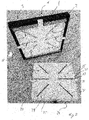
- Figure 1 shows an embodiment of the facing plate 1 according to the invention schematically in a top or plan view.
- the facing plate 1 has a base body 2 with an upper side 3 pointing out of the plane of the drawing and an underside 4 opposite the upper side 3 and pointing into the plane of the drawing.
- the facing plate 1 has an essentially square shape.
- the covering plate 1 can, however, also be shaped differently and, for example, rectangular, polygonal with precisely, more or less than four corners or also round, oval or irregularly shaped.
- Lateral sides 5 - 8 of the base body 2 connect its top 3 with its bottom 4.
- the lateral sides 5 - 8 can run perpendicular to the top 3.
- at least one of the lateral sides 5-8 can form an angle with the upper side 3 which is smaller than 270 °.
- the upper side 3 of the base body 2 can provide a surface of a path, for example a walkway or driveway.
- the base body 2 has at least one light-permeable section and, in the exemplary embodiment, FIG Figure 1 a total of six light-permeable sections 9-14.
- the base body 2 can have more or less than six and for example two, three, four, five, seven, eight, nine or between ten and twenty or even more light-permeable sections.
- At least one or all of the light-permeable sections 9-14 extend from the upper side 3 through the main body 2. Preferably, one or all of the light-permeable sections 9-14 extend perpendicular to the upper side 3 through the main body 2.
- the at least one light-permeable section 9-14 can be shaped as desired and, for example, curved along the top side 3. In the embodiment of Figure 1 however, the light-permeable sections 9-14 are straight and run along imaginary rays away from their common point of intersection. The point of intersection can be arranged at a distance from selected or from all of the light-transmissive sections 9-14. In each case three of the light-permeable sections 9, 10, 11 and / or 12, 13, 14 can be arranged to run at an angle between 20 ° and 60 ° and, for example, at an angle of 45 °.
- a central light-permeable section 10, 13 can be flanked by two light-permeable sections 9, 11 or 12, 14.
- the light-permeable sections 9, 12 and / or 11, 14 can extend at an angle to one another which is between 60 ° and 120 ° and, for example, 90 °.
- connection lines 15, 16, 17 which protrude through the lateral side 6 into the covering plate 1.
- the number of connection lines can be greater or less than three, depending on the electrical or electronic requirements.
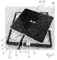
- Figure 2 shows the embodiment of Figure 1 in a schematic perspective view and with a lighting means 20.
- the covering plate 1 has a receiving trough 21 for the illuminant 20 on its underside 4.
- the receiving trough 21 opens away from the top 3.
- the light-permeable sections 9-14 extend from the top 3 to the receiving trough 21.
- the receiving trough 21 is provided by a receiving shell 22 inserted into the base body 2.
- the receiving trough 21 can, however, also be provided without the receiving shell 22 and in particular by the base body 2.
- FIG Figure 2 be shown and provided with a mounting shell 23.
- the mounting shell 23 can be used together with the lighting means 20 in the receiving trough 21.
- One side of the mounting shell 23 which, when the mounting shell 23 is inserted into the receiving cavity 21, faces into the receiving cavity 21, can be designed essentially complementary to the receiving cavity 21.
- the mounting shell 23 can have a mounting trough 24 which opens away from the top side 3 of the base body 2 and which, in the view of FIG Figure 2 is covered by an end plate 25 of the receiving shell 22.
- the lighting means 20 can be received at least in sections in the mounting recess 24.
- the end plate 25 can have at least one light-permeable section which is arranged such that it at least partially overlaps the at least one light-permeable section 9-14 of the base body 2.
- the end plate 25 of the mounting shell 23 has light-permeable sections 26 - 31, the size, position and alignment of which essentially correspond to the light-permeable sections 9 - 14 of the base body 2.
- the number of light-permeable sections 26 - 31 of the mounting shell 23 can correspond to the number of light-permeable sections 9 - 14 of the base body 2.
- the mounting shell 23 can be attached to the receiving shell 22 and / or to the base body 2 in a captive and non-destructive manner.
- the mounting shell 23 can thus have at least two fastening projections 32, 33 extending away from the mounting recess 24.
- the fastening projections 32, 33 can protrude from the receiving trough 21 when the mounting shell 23 is inserted into the receiving trough 21.
- the fastening projections 32, 33 can rest on an edge 34 of the underside 4 of the base body 2 that runs around the receiving trough 21 at least in sections.
- the fastening projections 32, 33 can extend away from the mounting recess 24 in opposite directions and / or be arranged on opposite sides of the mounting shell 23. Individual or all of the fastening projections 32, 33 can be channel-shaped and open away from the end plate 25. In the embodiment of Figure 2 however, the fastening projections 32, 33 are designed in the shape of a bar and can be arranged at a distance from the end plate 25. For example, the fastening projections 32, 33 can be aligned with a free end pointing away from the end plate 25 of a lateral side 35 of the mounting shell 23 that delimits the end plate 25 at least on one side.
- the lateral side 35 can extend perpendicular to the end plate 25 and at least partially encircle this and the mounting recess 24.
- the mounting shell 23 can have a plurality of lateral sides 35.
- At least one or all of the fastening projections 32, 33 can be embedded in the base body 2 and, for example, in its edge 34. At least one of the fastening projections 32, 33 can have a through opening 36, 37 which extends perpendicularly to the end plate 25 and is designed to receive a fastening screw.
- the mounting shell 23 is attached to the base body 2 and / or to the receiving shell 22 with the aid of the fastening screw or a plurality of fastening screws.
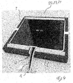
- Figure 3 shows the embodiment of the previous figures schematically in a further perspective view.
- the lighting means 20 is arranged in the mounting recess 24.
- the illuminant 20 is shown in FIG Figure 3 however, enclosed by a potting agent 38, so that the illuminant 20 in the Figure 3 is covered by the potting agent 38.
- the potting agent 38 can essentially completely fill the assembly depression 24.
- the lighting means 20 and the mounting shell 23 can be fastened to one another by the potting means 38 or otherwise and, for example, non-positively or positively. If the lighting means 20 and the mounting shell 23 are attached to one another, they can together form a lighting module 39 that can be handled in one piece.
- connection lines 15, 16, 17 can extend through the lateral side 35 or through one of the lateral sides 35 of the mounting shell 23 into the mounting recess 24.
- the lateral side 35 can have an opening for each connection line. In the exemplary embodiment shown, however, all connection lines 15, 16, 17 run through a common opening 40 on the lateral side 35.
- a closure plate 41 can be provided through which the Connecting lines 15, 16, 17 extend. The closure plate 41 can against the Connection lines 15, 16, 17 and seal against the lateral side 35 so that only insignificant amounts, if any, of the potting agent 38 can escape through the common opening 40.
- Figure 4 shows the exemplary embodiment of the previous figures, the lighting means 20 with the mounting shell 23 being inserted into the receiving trough 21 provided by the base body 2.
- the connection lines 15, 16, 17 can run through a channel-shaped cable groove 42.
- the cable groove 42 can run through the base body 2 and in particular through its edge 34 and open away from the top 3 of the base body 2.
- the cable groove 42 can extend from the receiving trough 21 to the lateral side 6 of the base body 2.
- Figure 5 shows the optional receiving shell 22 with the mounting shell 23, the receiving shell 22 providing the receiving trough 21 and the mounting shell 23 being arranged in the receiving trough 21.
- the receiving trough 21 and the mounting trough 24 open in identical directions.
- the receiving shell 22 has receiving channels 43-45, the fastening projections 32, 33 being inserted into the receiving channels 43, 44.
- the receiving channel 45 can be inserted into the cable groove 42 of the base body 2 and the connecting lines 15, 16, 17 can run through the receiving channel 45.
- the common opening 40 can be arranged between the receiving channel 45 and the mounting recess 24.
- Figure 6 shows the mounting shell 23, which can also be inserted into the receiving trough 21 of the base body 2 without the receiving shell 22.
- the mounting shell 23 can have the receiving channel 45 for receiving the connecting lines 15, 16, 17.
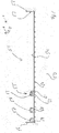
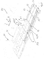
- FIG. 7 shows an embodiment of the installation rail 50 according to the invention in a schematic front view.
- the installation rail 50 can be designed for the installation of covering plates and in particular covering plates 1 according to the invention for a path.
- the installation rail 50 is essentially channel-shaped and has a receiving opening 51 for at least one covering plate 1.
- the installation rail 50 has a side wall 52 adjoining the receiving opening 51.
- the side wall 52 is provided with a counter-attachment element 53 for the facing plate 1.
- the counter-attachment element 53 projects from the side wall 52 in the illustrated embodiment. Alternatively this can Counter-mounting element 53 can be formed as a recess formed in the side wall 52, for example a groove.
- the installation rail 50 can have a base 54 that contacts the side wall 52. Furthermore, the installation rail 50 can have a support projection 55 that extends from the base 54 in the direction of the receiving opening.
- the support projection 55 can be arranged at a distance from the counter attachment element 53.
- the side wall 52 can project beyond the at least one support projection 55 in a height direction H pointing from the base 54 into the receiving opening 51.
- the direction can be perpendicular to the floor 54.
- the installation rail 50 can have a further side wall 56.
- the receiving opening 51 can extend between the side walls 52, 56.
- the at least one support projection 55 can be arranged closer to one of the side walls 52, 56 than to the other of the side walls 56, 52.
- the support projection 55 is arranged further away from the side wall 52 having the counter-attachment element 53 than from the other side wall 56.
- the support projection 55 or a further support projection 57 can adjoin one of the side walls 52, 56 and in particular the side wall 56 which is opposite the side wall 52 having the counter-attachment element 53.
- the side wall 56, to which the at least one support projection and in particular the further support projection 57 adjoins, can form one side of the support projection 57. Furthermore, the side wall 56 can protrude beyond the at least one supporting projection 55, 57 in the direction pointing away from the base 54.
- the installation rail 50 has several and in particular three support projections 55, 57, 58. Selected or all of the support projections 55, 57, 58 can have at least one cavity extending along a longitudinal direction L of the installation rail 50.
- the longitudinal direction L extends in the Figure 1 perpendicular to the plane of the drawing.
- the installation rail 50 extends in the longitudinal direction L and can have a cross-section that is essentially constant along the longitudinal direction L transversely to the longitudinal direction L.
- the installation rail 50 can be designed as an explosive body along its longitudinal direction L.
- the supporting projections 55, 57, 58 can be arranged at a distance from one another.
- the at least one support projection 55 or selected one or all support projections 55, 57, 58 can have at least one or even two cavities 59-62 extending along the longitudinal direction L of the installation rail 50. If the respective support projection 55, 57, 57 has two cavities 61, 62, these can be separated from one another at least in sections by an inner wall 63 of the support projection 55. In the embodiment of Figure 7 the cavities 61, 62 are arranged one behind the other perpendicular to the receiving opening 51 and / or to the bottom 54.
- the built-in rail 50 can have at least one spacer 64 on an underside 63 of the base 54 pointing away from the receiving opening 51. If the installation rail 50 has a plurality of spacers 64, these can be arranged transversely to the longitudinal direction L and, for example, spaced apart from one another in the width direction B. For example, one spacer 64 can each be aligned perpendicular to the bottom 54 with one of the side walls 52, 56, that is to say arranged in the height direction H directly in front of the respective side wall 52, 56. Additionally or alternatively, a spacer 64 or a plurality of spacers 64 can be arranged between the side walls 52, 56.
- the spacers 64 can be essentially T-shaped, wherein the transverse line can be arranged at the end of the spacer 64 pointing away from the top side 54.
- the spacer 64 can also be designed to serve as a surface enlargement and / or additional anchoring point, for example as an undercut, for gluing and / or mounting the built-in rail 50, for example in the mortar bed.
- Figure 8 shows an embodiment of the laying system 70 according to the invention schematically in a perspective view.
- the laying system 70 is shown with the built-in rail 50, with several covering plates 1 and with several cover plates 71.
- the same reference symbols are used for elements that correspond in function and / or structure to elements of the previous exemplary embodiments.
- the facing plates 1 are arranged one behind the other along the longitudinal direction L.
- the facing plates 1 In the width direction B of the built-in rail 50 running transversely to the longitudinal direction L the facing plates 1 can be placed on the counter attachment element 53.
- the covering plates 1 In order to prevent the covering plates 1 from being removed from the installation rail 50 in the height direction H running transversely to the longitudinal direction L and to the width direction B, the covering plates 1 have an attachment element 72 on the lateral side 8, which can be opposite the lateral side 6 on.
- the attachment element 72 can be shaped at least partially complementary to the counter attachment element 53 and secure the position of the respective facing plate 1 in a form-fitting manner.
- the illustrated embodiment is the attachment element 72 as a parallel to the top 3 and / or to in the Figure 8 Not visible underside 4 extending recess formed in the lateral side 8.
- the recess can be designed as a groove.
- the attachment element 72 and the counter attachment element 53 can be shaped complementary to one another.
- a width direction of the covering plate 1 can run parallel to the longitudinal direction L of the installation rail 50.
- the attachment element 72 can extend completely over the lateral side 8 along the width direction B of the facing plate 1 running parallel to the upper side 3 and / or to the lower side 4.
- the facing plate 1 and in particular its base body 2 can be formed with a holding projection 73.
- the holding projection 73 can be arranged at a distance from the upper side 3 and, for example, in alignment with the lower side 4 of the facing plate 1.
- the facing plate 1 adjoins the side wall 52 having the counter-mounting element 53.
- the optional cover plate 71 can be arranged between the facing plate 1 and the side wall 56, which is opposite the side wall 52 having the counter-attachment element 53.
- the cover plate 71 can rest on the at least one support projection, on selected ones of the support projections or on all of the support projections 55, 58, 57.
- the cover plate 71 can in particular be fastened repeatedly and detachably to the installation rail 50.
- the cover plate 71 can at least one of the support projections 55, 57, 58 be attached.
- the support projection 58, to which the cover plate 71 is fastened can have a fastening element, for example a screw receptacle, the cover plate 71 being fastened to the holding element and thus to the installation rail 50 with the aid of a counter-fastening element 74, for example a screw.
- the cover plate 71 can have, on its lateral side 75 facing the facing plate 1, an opposing retaining projection 76, which is arranged in the height direction H of the facing plate 1 behind the retaining projection 73 and, together with the opposing attachment element 53, enables the facing plate 1 to be unintentionally removed from the installation rail 50 prevented.
- the height direction of the covering plate 1 can run parallel to the height direction H of the mounting rail 50 when the covering plate is inserted and can extend from the bottom 4 to the top 3 of the covering plate 1.
- the holding projection 73 and the counter-holding projection 75 thus overlap in the height direction H.
- overlap means that a projection of an element in said direction overlaps the other element.
- the holding projection 73 and the counter-holding projection 76 can contact one another or be spaced apart from one another when the covering plate 1 and the cover plate 71 are arranged in the installation rail 50.
- At least the support projection 55 arranged closest to the facing plate 1 or adjacent to its lateral side 6 can have at least one interruption 77 along the longitudinal direction L.
- the interruption 77 can overlap the cable groove 42 of a covering plate 1 inserted into the installation rail 50 and / or be in alignment therewith.
- the cable groove 42 can therefore open away from the side wall 52 and / or towards the support body 55 or towards its interruption 77.
- the support projection 55 can have several interruptions 77, which are spaced from one another along the longitudinal direction L of the installation rail 50 such that the cable grooves 42 of all or selected ones of the covering panels 1 are each aligned with one of the interruptions 77 or overlap them.
- the connecting lines 15, 16, 17 can extend through the cable groove 52 and the interruption 77 and between the at least one Support projection 55 and the side wall 56 or between the support projection 55 and one of the support projections 57, 58 extend.
- Figure 9 shows the embodiment of Figure 8 in a schematic sectional illustration, the cutting plane being spanned by the width direction B and the height direction H.
- the longitudinal direction L points into the plane of the drawing.
- FIG. 9 shows Figure 9 that the cavities 61, 62 in contrast to the embodiment of Figure 7 can also be arranged one behind the other along the width direction B.
- the inner wall 63 can thus extend along the height direction H and the longitudinal direction L.
- At least one support rail 78, 79, 80 can be arranged on the floor 54 of the built-in rail 50, wherein the at least one support rail 78, 79, 80 can project beyond the floor 54 in the height direction H and extend along the longitudinal direction L. In the vertical direction H, the at least one support rail 78, 79, 80 can be protruded from the at least one support projection 55, 57, 58.
- the covering plate 1 and in particular the edge 34 of the base body 2 can rest on the at least one support rail 78, 79, 80 when the covering plate 1 is inserted into the installation rail 50.
- Figure 10 shows the embodiment of Figures 8 and 9 in a schematic perspective view and with connection lines 15, 16, 17 shown schematically.
- Connection lines 15, 16, 17 running directly to one of the facing panels 1 extend in the illustrated embodiment from the respective facing panel 1 between the support projection 55 having the interruptions 77 and the projection 55 as seen the facing plate 1 following support projection 58.
- a first channel 81 extends for the connection lines 15, 16, 17.
- the connection lines 15, 16, 17 can run to a distributor 83, for which the support projections 57, 58 can have an interruption.
- Lines running between a plurality of distributors 83 or lines 84 running from the distributor 83 to a control system can extend through a further channel 82, wherein the channel 82 can be arranged between the support projections 57, 58.
- the lines 15, 16, 17 and / or the distributor 83 can be part of a control system of the laying system 70.
- Figure 11 illustrates a possible embodiment of a method for providing information on a floor, in particular a path, in which selected sections of the floor are selectively illuminated from below.
- the floor 100 is shown as a platform, that is to say as a footpath.
- the floor 100 can also be a surface of a driveway, for example a street or a parking lot.
- the laying system 70 can be used to carry out the method.
- the laying system 70 can selectively backlight selected transparent sections 9-14 of all or selected covering panels 1.
- the laying system 70 in the embodiment of FIG Figure 11 Indications as to where the doors of a train 101 that is about to stop at the platform will be.
- the train 101 is in the Figure 11 already shown to explain the exemplary method.
- the information given by the laying system 70 can of course also be displayed by the laying system 70 when the train 101 stops at the platform.
- light-permeable sections 9-14 are backlit in areas of the floor 100 on which the doors of the train 101 are or will be located. Light-permeable sections 9-14 in areas where no train doors are expected can not be backlit or be backlit in a different way. In order to lead people to the entry areas where the doors are expected, light-permeable sections 9, 11 or 12, 14 of the covering panels 1 can be located in areas that are spaced apart from the train doors Entrance areas and / or adjoining the entrance areas are essentially backlit in the shape of an arrow.
- the selective backlighting of individual light-permeable sections of the floor 100 can be adapted to the respective circumstances.
- the boarding areas can be adapted to different trains and / or trains that stop at different positions.
- the train 101 can communicate the position of the train doors directly or indirectly to the laying system 70, for example by the train 101 transmitting the distances between the train doors and the train 101, the laying system 70 or an external system determining the position of the train 101 on the platform.
Abstract
Die Erfindung betrifft eine Belagplatte (1), eine Einbauschiene (50) für eine Belagplatte (1) und ein Verlegesystem (70) mit einer Belagplatte (1) und einer Einbauschiene (50). Um das Verlegesystem (70) einfach verbauen und Hinweise flexibel bereitstellen zu können, weist die Belagplatte (1) Licht durchlässige Abschnitte (9 - 14) auf, die von einem Leuchtmittel (20) selektiv hinterleuchtbar sind, um die Hinweise an der Oberfläche der Belagplatte (1) sichtbar zu machen.The invention relates to a covering plate (1), an installation rail (50) for a covering plate (1) and an installation system (70) with a covering plate (1) and an installation rail (50). In order to be able to install the laying system (70) easily and provide information flexibly, the covering plate (1) has light-permeable sections (9-14) which can be selectively backlit by a lamp (20) in order to display the information on the surface of the covering plate (1) to make visible.
Description
Die Erfindung betrifft eine Belagplatte mit einem Grundkörper, der eine Oberseite und eine von der Oberseite weg weisende Unterseite aufweist.The invention relates to a covering plate with a base body which has an upper side and an underside pointing away from the upper side.
Ferner betrifft die Erfindung eine Einbauschiene zum Einbauen von Belagplatten für eine Oberfläche, etwa eines Wegs, einer Wand oder einer Decke, wobei die Einbauschiene im Wesentlichen kanalförmig und mit einer Aufnahmeöffnung für zumindest eine Belagplatte ausgebildet ist.The invention also relates to an installation rail for installing covering panels for a surface, for example a path, a wall or a ceiling, the installation rail being essentially channel-shaped and having a receiving opening for at least one covering panel.
Darüber hinaus betrifft die Erfindung ein Verlegesystem mit mindestens einer Belagplatte und wenigstens einer Einbauschiene.The invention also relates to a laying system with at least one covering plate and at least one installation rail.
Belagplatten, Einbauschienen für Belagplatten und Verlegesysteme mit Belagplatten und Einbauschienen sind allgemein bekannt. So werden Belagplatten oftmals für Wege verwendet, um eine begeh- und/oder mit Fahrzeugen befahrbare Oberfläche bereitzustellen. Insbesondere kann die Oberseite der Belagplatte die Oberfläche bereitstellen. Ein Weg kann beispielsweise ein Fußweg, eine Straße, ein Parkplatz, aber auch ein Bahnsteig, eine Fläche oder bei in einem Flughafenterminal oder in einer Messehalle sein. Alternativ werden Belagplatten zur Bereitstellung von Wand- oder Deckenoberflächen verwendet. Die Oberfläche kann außerhalb oder innerhalb eines Gebäudes vorhanden sein. Einbauschienen können die Positionierung der Belagplatten beim Bau des Weges erleichtern sowie unterhalb der Belagplatte einen Raum zur Installation, beispielsweise von Fluidleitungen bereitstellen. Bei Verlegesystemen können sie Belagplatten und die Einbauschienen aneinander und an den zu bauenden Weg angepasst sein.Covering plates, installation rails for covering plates and laying systems with covering plates and installation rails are generally known. So paving plates are often used for paths to provide a surface that can be walked on and / or driven by vehicles. In particular, the upper side of the covering plate can provide the surface. A path can be, for example, a footpath, a street, a parking lot, but also a platform, an area or in an airport terminal or in a trade fair hall. Alternatively, covering panels are used to provide wall or ceiling surfaces. The surface can be outside or inside a building. Installation rails can facilitate the positioning of the paving slabs during the construction of the path and provide space below the paving slab for the installation, for example of fluid lines. In the case of laying systems, the covering panels and the installation rails can be adapted to each other and to the path to be built.
Wird die Belagplatte auf einen Boden gelegt, um die Oberfläche des Weges bereitzustellen, kann die Belagplatte auch als Bodenplatte bezeichnet werden. Wird die Belagplatte an einer Wand angebracht, um die Oberfläche der Wand bereitzustellen, kann die Belagplatte auch als Wandplatte bezeichnet werden. Wird die Belagplatte an einer Decke angebracht, um die Oberfläche der Decke bereitzustellen, kann die Belagplatte auch als Deckenplatte bezeichnet werden.If the covering plate is placed on a floor in order to provide the surface of the path, the covering plate can also be referred to as a floor plate. If the covering plate is attached to a wall in order to provide the surface of the wall, the covering plate can also be referred to as a wall plate. If the covering plate is attached to a ceiling in order to provide the surface of the ceiling, the covering plate can also be referred to as a ceiling plate.
Zur Information oder Orientierung werden Informationsinhalte oder Orientierungshinweise, wie etwa Texte, Piktogramme oder Pfeile, auf Oberflächen aufgebracht. Die Informationen und Orientierungshinweise lassen sich jedoch nicht einfach ändern, sodass die Hinweise nicht flexibel änderbar sind.For information or orientation, informational content or orientation instructions, such as texts, pictograms or arrows, are placed on surfaces upset. However, the information and orientation notes cannot simply be changed, so that the notes cannot be changed flexibly.
Der Erfindung liegt also die Aufgabe zugrunde, eine einfach bereit- oder herzustellende Oberfläche bereitzustellen, wobei Informationen oder Orientierungshinweise flexibel geändert werden können.The invention is therefore based on the object of providing a surface that is easy to prepare or produce, with information or orientation instructions being able to be changed flexibly.
Für die eingangs genannte Belagplatte ist die Aufgabe dadurch gelöst, dass die Unterseite eine Aufnahmemulde zur zumindest abschnittsweisen Aufnahme eines Leuchtmittels aufweist. Der Grundkörper weist wenigstens einen Licht durchlässigen und mindestens einen Licht undurchlässigen Abschnitt auf. Der wenigstens eine Licht durchlässige Abschnitt erstreckt sich von der Oberseite bis zur Aufnahmemulde. Der Grundkörper weist eine die Oberseite mit der Unterseite verbindende laterale Seite auf, wobei an der lateralen Seite ein Anbringelement zur Anbringung der Belagplatte an eine Einbauschiene aufweist. Die Aufnahmemulde kann auch als Aufnahmesenke oder als Aufnahmevertiefung bezeichnet werden.For the facing plate mentioned at the beginning, the object is achieved in that the underside has a receiving trough for receiving a light source at least in sections. The main body has at least one light-permeable and at least one light-impermeable section. The at least one light-permeable section extends from the top to the receiving trough. The base body has a lateral side that connects the upper side with the lower side, with an attachment element on the lateral side for attaching the covering plate to an installation rail. The receiving trough can also be referred to as a receiving sink or a receiving recess.
Die Ausformung des Grundkörpers mit dem wenigstens einen Licht durchlässigen und dem mindestens einen Licht undurchlässigen Abschnitt sowie die Ausbildung der lateralen Seite mit dem Anbringelement können jeweils für sich und unabhängig voneinander vorteilhaft sein.The shaping of the base body with the at least one light-permeable and the at least one light-impermeable section and the formation of the lateral side with the attachment element can each be advantageous individually and independently of one another.
Die Erfindung ist für die eingangs genannte Einbauschiene dadurch gelöst, dass die Einbauschiene eine an die Aufnahmeöffnung angrenzende Seitenwand aufweist, wobei die Seitenwand mit einem Gegenanbringelement versehen ist. Das Gegenanbringelement springt von der Seitenwand vor oder ist als ein in der Seitenwand ausgebildeter Rücksprung ausgeformt.The invention is achieved for the installation rail mentioned at the outset in that the installation rail has a side wall adjoining the receiving opening, the side wall being provided with a counter-attachment element. The counter attachment element protrudes from the side wall or is formed as a recess formed in the side wall.
Für das eingangs genannte Verlegesystem ist die Aufgabe dadurch gelöst, dass die mindestens eine Belagplatte die erfindungsgemäße Belagplatte ist und die wenigstens eine Einbauschiene die erfindungsgemäße Einbauschiene ist.For the laying system mentioned at the beginning, the object is achieved in that the at least one covering plate is the covering plate according to the invention and the at least one installation rail is the installation rail according to the invention.
Durch das Anbringelement und das Gegenanbringelement lässt sich die Belagplatte leicht an der Einbauschiene anbringen, wobei das Gegenanbringelement eine verbaute Position der Belagplatte vorgeben kann. Ein den Licht durchlässigen Abschnitt hinterleuchtendes Leuchtmittel kann beispielsweise ein- und ausgeschaltet oder dessen Leuchtfarbe geändert werden, um Informationen oder Orientierungshinweise einfach und schnell zu ändern.By means of the attachment element and the counter attachment element, the covering plate can easily be attached to the installation rail, wherein the counter attachment element can predetermine an installed position of the covering plate. A light source that backlights the section that is transparent to light can, for example, be switched on and off or its luminous color can be changed in order to change information or orientation notes easily and quickly.
Die Erfindung kann durch weitere, jeweils für sich vorteilhafte und, soweit nicht anders beschrieben, ohne weiteres kombinierbare Ausgestaltungen weiter verbessert werden. Auf diese weiteren möglichen Ausgestaltungen und deren Vorteile wird im Folgenden eingegangen.The invention can be further improved by further, in each case advantageous and, unless otherwise described, easily combinable embodiments. These further possible configurations and their advantages are discussed below.
Gemäß einer möglichen Ausgestaltung ist das Anbringelement zumindest teilweise als ein sich parallel zur Oberseite und/oder zur Unterseite erstreckender Vorsprung oder Rücksprung ausgebildet. Ein Vorteil dieser Ausgestaltung kann sein, dass das Anbringelement einfach in oder auf das Gegenanbringelement geschoben werden kann, um die Belagplatte zu positionieren und/oder an der Einbauschiene anzubringen.According to one possible embodiment, the attachment element is at least partially designed as a projection or recess extending parallel to the top and / or to the bottom. An advantage of this configuration can be that the attachment element can simply be pushed into or onto the counter attachment element in order to position the covering plate and / or to attach it to the installation rail.
Gemäß einer möglichen Ausgestaltung erstreckt sich das Anbringelement entlang einer parallel zur Oberseite und/oder zur Unterseite verlaufenden Breitenrichtung des Grundkörpers vollständig über die laterale Seite. Ein Vorteil dieser Ausgestaltung kann sein, dass sich die Belagplatte einfacher montieren lässt.According to one possible embodiment, the attachment element extends completely over the lateral side along a width direction of the base body that runs parallel to the upper side and / or to the lower side. An advantage of this configuration can be that the facing plate can be mounted more easily.
Gemäß einer möglichen Ausgestaltung weist die Belagplatte eine die Aufnahmemulde ausformende und zumindest abschnittsweise in den Grundkörper eingelassene Aufnahmeschale auf. Ein Vorteil dieser Ausgestaltung kann sein, dass die Aufnahmemulde durch die Aufnahmeschale einfach vorgefertigt sein kann.According to a possible embodiment, the covering plate has a receiving shell that forms the receiving trough and is at least partially embedded in the base body. An advantage of this configuration can be that the receiving trough can simply be prefabricated by the receiving shell.
Alternativ kann gemäß einer möglichen Ausgestaltung auf die Aufnahmeschale verzichtet werden. Wird auf die Aufnahmeschale verzichtet, kann die Aufnahmemulde anders ausgeformt und beispielsweise in einen vorgefertigten Grundkörper eingefräst werden. Wird der Grundkörper durch Gießen gefertigt, kann die Aufnahmemulde während des Gießens und zum Beispiel durch ein Gusswerkzeug ausgeformt werden.Alternatively, according to a possible embodiment, the receiving tray can be dispensed with. If the receiving shell is dispensed with, the receiving trough can be shaped differently and, for example, milled into a prefabricated base body. If the base body is manufactured by casting, the receiving trough can be formed during the casting and, for example, by a casting tool.
Gemäß einer möglichen Ausgestaltung weist die Belagplatte eine in die Aufnahmemulde eingesetzte Montageschale auf. Die Montageschale kann so in die Aufnahmemulde eingepresst sein, dass sie kraftschlüssig in der Aufnahmemulde gehalten ist. Alternativ kann die Montageschale auch anders in der Aufnahmemulde und zum Beispiel durch Verguss oder Verklebung oder Verschraubung gehalten sein. Die in die Aufnahmemulde weisende Seite der Montageschale kann komplementär zur Aufnahmemulde ausgeformt sein. Ein Vorteil dieser Ausgestaltungen kann sein, dass die Montageschale einfach in die Aufnahmemulde einsetzbar ist und einen vordefinierten Montageraum für das Leuchtmittel bereitstellen kann.According to one possible embodiment, the covering plate has a mounting shell inserted into the receiving trough. The mounting shell can be pressed into the receiving recess in such a way that it is held in the receiving recess with a force fit. Alternatively, the mounting shell can also be held differently in the receiving recess and, for example, by potting or gluing or screwing his. The side of the mounting shell pointing into the receiving recess can be shaped complementary to the receiving recess. One advantage of these configurations can be that the mounting shell can be easily inserted into the receiving trough and can provide a predefined mounting space for the lighting means.
Gemäß einer möglichen Ausgestaltung weist die Montageschale zumindest ein Befestigungselement zur Befestigung des Leuchtmittels und/oder mindestens eines anderen Bauteils auf. Das andere Bauteil kann ein elektrisches oder ein elektronisches Bauteil und beispielsweise eine mit elektrischen und/oder elektronischen Komponenten bestückte Platine sein. Das Leuchtmittel kann ein weiteres elektrisches oder ein elektronisches Bauteil und/oder eine mit elektrischen und/oder elektronischen Komponenten bestückte Platine aufweisen. Ein Vorteil dieser Ausgestaltung kann sein, dass das Leuchtmittel oder andere Bauteile einfacher zu montieren sind.According to one possible embodiment, the mounting shell has at least one fastening element for fastening the illuminant and / or at least one other component. The other component can be an electrical or an electronic component and, for example, a circuit board equipped with electrical and / or electronic components. The lighting means can have a further electrical or an electronic component and / or a circuit board equipped with electrical and / or electronic components. An advantage of this configuration can be that the lighting means or other components are easier to assemble.
Gemäß einer möglichen Ausgestaltung bildet die Montageschale eine sich von der Oberseite weg öffnende Montagemulde zur zumindest abschnittsweisen Aufnahme eines Leuchtmittels aus. Ein Vorteil dieser Ausgestaltung kann sein, dass das Leuchtmittel einfach durch die Öffnung der Montagemulde in die Montagemulde einsetzbar ist oder durch die Öffnung der Montagemulde in diese hineinleuchten kann.According to a possible embodiment, the mounting shell forms a mounting recess that opens away from the top for receiving a light source at least in sections. An advantage of this embodiment can be that the lighting means can be inserted simply through the opening of the mounting recess into the mounting recess or can shine into the latter through the opening of the mounting recess.
Gemäß einer möglichen Ausgestaltung weist die Montageschale an ihrem der Oberseite zugewandten Ende eine Abschlussplatte auf. Die Abschlussplatte kann je nach Orientierung der Montageschale als Boden oder als Dach der Montageschale bezeichnet werden. Die Abschlussplatte weist zumindest einen Licht durchlässigen Abschnitt auf, der so angeordnet ist, dass er den mindestens einen Licht undurchlässigen Abschnitt des Grundkörpers zumindest teilweise oder sogar vollständig überlappt. Überlappen kann bedeuten, dass eine Projektion des Licht durchlässigen Abschnitts der Abschlussplatte entlang einer Höhenrichtung der Belagplatte und/oder entlang einer Leuchtrichtung des verbauten Leuchtmittels den Licht durchlässigen Abschnitt des Grundkörpers schneidet oder sogar durchdringt. Ein Vorteil dieser Ausgestaltung kann sein, dass von dem Leuchtmittel abgegebene Licht ohne weiteres zum Licht durchlässigen Abschnitt des Grundkörpers gelangen kann.According to one possible embodiment, the mounting shell has an end plate at its end facing the top. Depending on the orientation of the mounting shell, the end plate can be referred to as the bottom or the roof of the mounting shell. The end plate has at least one light-permeable section, which is arranged such that it at least partially or even completely overlaps the at least one light-impermeable section of the base body. Overlapping can mean that a projection of the light-permeable section of the end plate along a height direction of the covering panel and / or along a lighting direction of the built-in illuminant intersects or even penetrates the light-permeable section of the base body. An advantage of this configuration can be that light emitted by the lighting means can easily reach the light-permeable section of the base body.
Gemäß einer möglichen Ausgestaltung weist die Belagplatte ein Leuchtmittel auf, wobei das Leuchtmittel und optional das wenigstens eine andere Bauteil in der Montagemulde vergossen ist. Ein Vorteil dieser Ausgestaltung kann sein, dass durch den Verguss das Leuchtmittel und optional das wenigstens eine andere Bauteil besser vor Umwelteinflüssen, zum Beispiel Feuchtigkeit oder Staub, geschützt ist.According to one possible embodiment, the covering plate has a light source, the light source and optionally the at least one other component being encapsulated in the assembly cavity. An advantage of this embodiment can be that the potting means that the lighting means and optionally the at least one other component are better protected from environmental influences, for example moisture or dust.
Gemäß einer möglichen Ausgestaltung bildet die Montageschale mit dem Leuchtmittel ein einstückig handhabbares Leuchtmodul aus. So kann das in der Montagemulde angeordnete Leuchtmittel lösbar oder unlösbar an der Montageschale befestigt und beispielsweise mit einem in der Montagemulde angeordneten Vergussmittel vergossen sein. Ein Vorteil dieser Ausgestaltung kann sein, dass das Leuchtmodul einfacher handhabbar und montierbar ist, wobei das Leuchtmittel gerade in der rauen Umgebung einer Baustelle als Teil des Leuchtmoduls besser gegen Beschädigungen und vor Umwelteinflüssen geschützt sein kann.According to one possible embodiment, the mounting shell and the lighting means form a light module that can be handled in one piece. Thus, the lighting means arranged in the mounting recess can be detachably or permanently attached to the mounting shell and, for example, encapsulated with a potting means arranged in the mounting recess. An advantage of this configuration can be that the light module is easier to handle and assemble, with the light source being better protected against damage and environmental influences as part of the light module, especially in the harsh environment of a construction site.
Gemäß einer möglichen Ausgestaltung weist das Leuchtmittel als Lichtquelle wenigstens eine LED und beispielsweise eine Vielzahl von LEDs oder LED-Gruppen auf. Die Lichtquelle kann mit optionalen Bauteilen auf einer Platine bereitgestellt sein. Das Leuchtmittel kann in die Montagemulde eingesetzt sein. Das Leuchtmittel und insbesondere dessen Platine kann in oder an der Montageschale und zum Beispiel an deren Befestigungsmittel befestigt sein. Zusätzlich oder optional zur Befestigung an der Montageschschale kann das Leuchtmittel und insbesondere dessen Platine von einem Vergussmaterial umgeben sein. Das Vergussmaterial kann transparent sein. Das Leuchtmittel und insbesondere dessen Platine kann nach dem Einbringen in die Montagemulde und optional nach dem Anschluss des Leuchtmittels an externe Elektrik- oder Elektronikkomponenten mit dem Vergussmaterial vergossen werden. Das Verlegesystem kann die externen Elektrik- oder Elektronikkomponenten aufweisen. Optional kann ein Deckel vorgesehen sein, mit dem die von der Oberseite des Grundkörpers weg weisende Öffnung der Montagemulde verschließbar ist. Im geschlossenen Zustand kann der Deckel gegen den Grundkörper und/oder gegen die Montageschale wasserdicht schließen. Ein Vorteil dieser Ausgestaltungen kann sein, dass die Belagplatte flexibel und einfach herstellbar sowie langlebig ist.According to one possible embodiment, the light source has at least one LED and, for example, a plurality of LEDs or LED groups as the light source. The light source can be provided with optional components on a circuit board. The lamp can be inserted into the mounting recess. The lamp and in particular its circuit board can be fastened in or on the mounting shell and, for example, on its fastening means. Additionally or optionally for attachment to the mounting shell, the lighting means and in particular its circuit board can be surrounded by a potting material. The potting material can be transparent. The illuminant and in particular its circuit board can be encapsulated with the potting material after it has been introduced into the mounting recess and optionally after the illuminant has been connected to external electrical or electronic components. The laying system can have the external electrical or electronic components. Optionally, a cover can be provided with which the opening of the mounting recess facing away from the top of the base body can be closed. In the closed state, the cover can close in a watertight manner against the base body and / or against the mounting shell. One advantage of these configurations can be that the facing plate can be produced flexibly and easily and is durable.
Gemäß einer möglichen Ausgestaltung ist die Montageschale unverlierbar und zerstörungsfrei lösbar an der Aufnahmeschale, an der Aufnahmemulde und/oder an einem außerhalb der Aufnahmemulde angeordneten Abschnitt des Grundkörpers befestigt.According to a possible embodiment, the mounting shell is captive and non-destructively detachable from the receiving shell, the receiving trough and / or on attached to a section of the base body arranged outside the receiving trough.
Ein Vorteil dieser Ausgestaltung kann sein, dass die Montageschale einfach tauschbar ist. Ist das Leuchtmittel beispielsweise in der Montageschale vergossen, kann es sein, dass sich das Leuchtmittel nicht mehr ohne weiteres von der Montageschale lösen lasst. Folglich ist es, etwa wenn das Leuchtmittel getauscht werden soll, möglich, die Montageschale mit dem Leuchtmittel zu tauschen.One advantage of this configuration can be that the mounting shell can be exchanged easily. If, for example, the illuminant is encapsulated in the mounting shell, it is possible that the illuminant can no longer be easily detached from the mounting shell. As a result, it is possible, for example, when the lamp is to be exchanged, to exchange the mounting shell with the lamp.
Gemäß einer möglichen Ausgestaltung ist das Leuchtmittel an der Montageschale befestigt, beispielsweise durch form- oder kraftschlüssige Befestigungselemente, oder durch Verguss. Gemäß einer möglichen Ausgestaltung können die Montageschale und das Leuchtmittel miteinander einstückig handhabbar verbunden sein. Ein Vorteil dieser Ausgestaltungen kann sein, dass die Belagplatte einfacher zu montieren ist.According to one possible embodiment, the illuminant is fastened to the mounting shell, for example by means of form-fitting or force-fitting fastening elements, or by potting. According to a possible embodiment, the mounting shell and the lighting means can be connected to one another in a manageable manner. One advantage of these configurations can be that the facing plate is easier to assemble.
Gemäß einer möglichen Ausgestaltung weist die Aufnahmeschale zwei sich jeweils von der Aufnahmemulde weg erstreckende Befestigungsvorsprünge auf. Ein Vorteil dieser Ausgestaltung kann sein, dass die Aufnahmeschale einfach am Grundkörper zu befestigen ist.According to a possible embodiment, the receiving shell has two fastening projections each extending away from the receiving trough. An advantage of this configuration can be that the receiving shell can be easily attached to the base body.
Gemäß einer möglichen Ausgestaltung erstrecken sich die Befestigungsvorsprünge womöglich in entgegengesetzten Richtungen von der Aufnahmemulde weg und/oder sind an entgegengesetzten Seiten der Aufnahmeschale angeordnet. Ein Vorteil dieser Ausgestaltungen kann sein, dass die sich von der Aufnahmemulde weg erstreckenden Befestigungsvorsprünge den Zugang zur Aufnahmemulde nicht behindern, beziehungsweise, dass die an den entgegengesetzten Seiten der Aufnahmeschale angeordneten Befestigungsvorsprünge die Aufnahmeschale so am Grundkörper halten können, dass die befestigte Aufnahmeschale auf die Befestigungsvorsprünge kein nennenswertes Drehmoment ausübt.According to a possible embodiment, the fastening projections possibly extend in opposite directions away from the receiving trough and / or are arranged on opposite sides of the receiving shell. An advantage of these configurations can be that the fastening projections extending away from the receiving trough do not hinder access to the receiving trough, or that the fastening projections arranged on the opposite sides of the receiving shell can hold the receiving shell on the base body in such a way that the fastened receiving shell on the fastening projections does not exert any significant torque.
Gemäß einer möglichen Ausgestaltung ist zumindest einer der Befestigungsvorsprünge kanalförmig und sich von der Oberseite der Belagplatte weg öffnend ausgeformt. Der durch den kanalförmigen Befestigungsvorsprung geformte Kanal kann auch im Grundkörper und insbesondere in dessen von seiner Oberseite weg weisenden Unterseite vorgesehen sein, insbesondere wenn auf die Aufnahmeschale verzichtet ist. Der Kanal kann sich von der Oberseite weg öffnen und sich von der Aufnahmemulde bis zu einer die Ober- mit der Unterseite verbindenden lateralen Seite des Grundkörpers erstrecken. Optional können mehrere Kanäle vorgesehen sein. Sind mehrere Kanäle vorgesehen, können diese an unterschiedlichen Seiten oder an einer ausgewählten Seite der Aufnahmemulde angeordnet sein. Der wenigstens eine Kanal kann in die Aufnahmemulde münden. Ein Vorteil dieser Ausgestaltungen kann sein, dass Anschlussleitungen für das Leuchtmittel einfach in dem wenigstens einen Kanal geführt sein können, ohne dass diese durch den Grundkörper im verbauten Zustand der Belagplatte gequetscht werden.According to one possible embodiment, at least one of the fastening projections is channel-shaped and is formed so that it opens away from the top of the facing plate. The channel formed by the channel-shaped fastening projection can also be provided in the base body and in particular in its underside pointing away from its upper side, in particular when on the Receiving tray is omitted. The channel can open away from the top and extend from the receiving trough as far as a lateral side of the base body that connects the top and bottom. Multiple channels can optionally be provided. If several channels are provided, these can be arranged on different sides or on a selected side of the receiving trough. The at least one channel can open into the receiving trough. One advantage of these configurations can be that connection lines for the lighting means can simply be guided in the at least one channel without these being squeezed by the base body when the covering plate is installed.
Gemäß einer möglichen Ausgestaltung sind die Befestigungsvorsprünge zumindest teilweise in den Grundkörper eingelassen. Ein Vorteil dieser Ausgestaltung kann sein, dass die Unterseite des Grundkörpers im verbauten Zustand der Belagplatte flächig aufliegt und überstehende Befestigungsvorsprünge nicht zum Kippeln der Belagplatte führen können.According to a possible embodiment, the fastening projections are at least partially embedded in the base body. An advantage of this configuration can be that the underside of the base body rests flat in the installed state of the covering plate and protruding fastening projections cannot cause the covering plate to tilt.
Gemäß einer möglichen Ausgestaltung weist die Aufnahmeschale von der Aufnahmemulde weg weisende Außenseiten auf. Von den Außenseiten springt jeweils mindestens einer der Befestigungsvorsprünge vor. An ausgewählten der Außenseiten ist wenigstens ein Befestigungselement angeordnet. Eine Projektion eines der Befestigungselemente überlappt entlang der von der Oberseite zur Unterseite verlaufenden Höhenrichtung des Grundkörpers einen der Befestigungsvorsprünge. Ein Vorteil dieser Ausgestaltung kann sein, dass die Aufnahmeschale einfach am Grundkörper zu befestigen ist.According to one possible embodiment, the receiving shell has outer sides pointing away from the receiving trough. At least one of the fastening projections protrudes from the outer sides. At least one fastening element is arranged on selected ones of the outer sides. A projection of one of the fastening elements overlaps one of the fastening projections along the height direction of the base body running from the top to the bottom. An advantage of this configuration can be that the receiving shell can be easily attached to the base body.
Gemäß einer möglichen Ausgestaltung weist zumindest eines der Befestigungselemente eine Schraubaufnahme für eine die Montageschale befestigende Befestigungsschraube auf. Optional und insbesondere wenn auf die Aufnahmeschale verzichtet ist, kann der Grundkörper mit der Schraubaufnahme versehen sein. Ein Vorteil dieser Ausgestaltung kann sein, dass die Montageschale einfach lösbar zu befestigen ist.According to one possible embodiment, at least one of the fastening elements has a screw receptacle for a fastening screw fastening the mounting shell. Optionally, and especially if the receiving shell is dispensed with, the base body can be provided with the screw receptacle. An advantage of this configuration can be that the mounting shell can be easily detachably attached.
Gemäß einer möglichen Ausgestaltung ist eine vom Anbringelement weg weisende Seite der Belagplatte mit einem Haltevorsprung ausgeformt. Ein Vorteil dieser Ausgestaltung kann sein, dass die Belagplatte aufgrund des auf der Seite, die vom Anbringelement weg weist, vorgesehenen Haltevorsprungs aneinander gegenüberliegenden Seiten gegen unautorisierte Entnahme aus der verbauten Position gesichert ist.According to one possible embodiment, a side of the facing plate facing away from the attachment element is formed with a retaining projection. An advantage of this configuration can be that the facing plate due to the on the side that from Attaching element points away, provided retaining projection is secured on opposite sides against unauthorized removal from the installed position.
Gemäß einer möglichen Ausgestaltung ist der Haltevorsprung beabstandet von der Oberseite angeordnet. Gemäß einer möglichen Ausgestaltung fluchtet der Haltevorsprung mit der Unterseite der Belagplatte. Ein Vorteil dieser Ausgestaltungen kann sein, dass die Belagplatte auf dem Haltevorsprung und einer der Seitenwände der Einbauschiene anliegen kann und somit einfach zu positionieren ist.According to one possible embodiment, the holding projection is arranged at a distance from the top. According to one possible embodiment, the holding projection is aligned with the underside of the facing plate. One advantage of these configurations can be that the covering plate can rest on the retaining projection and one of the side walls of the installation rail and is therefore easy to position.
Gemäß einer möglichen Ausgestaltung weist die Belagplatte und beispielsweise deren Grundkörper eine kanalförmige Kabelnut auf, die sich von der Oberseite weg öffnet und von der Aufnahmemulde zu einer der lateralen Seiten führt. Die Kabelnut kann separat oder durch den oben genannten Kanal ausgebildet sein. Ein Vorteil dieser Ausgestaltung kann sein, dass die Belagplatte einfach und flexibel mit Energie und/oder Signalen für das Leuchtmittel versorgt werden kann.According to one possible embodiment, the covering plate and, for example, its base body have a channel-shaped cable groove which opens away from the top and leads from the receiving trough to one of the lateral sides. The cable groove can be formed separately or through the above-mentioned channel. An advantage of this configuration can be that the covering plate can be supplied with energy and / or signals for the lighting means in a simple and flexible manner.
Gemäß einer möglichen Ausgestaltung weist die Einbauschiene einen die Seitenwand kontaktierenden Boden und mindestens einen sich vom Boden in Richtung auf die Aufnahmeöffnung erstreckenden Stützvorsprung auf. Der Stützvorsprung ist beabstandet zum Gegenanbringelement angeordnet. Ein Vorteil dieser Ausgestaltung kann sein, dass die Belagplatte oder eine andere Platte, die Teil des Weges sein kann, im verbauten Zustand auf dem Stützvorsprung aufliegt und vom Stützvorsprung sowie optional vom Gegenanbringelement, gestützt wird, sodass ein zwischen der Belagplatte oder der anderen Platte und dem Boden der Einbauschiene freies Volumen verbleibt. Das freie Volumen kann zum Verlegen von Anschlussleitungen vorgesehen sein.According to a possible embodiment, the installation rail has a base contacting the side wall and at least one support projection extending from the base in the direction of the receiving opening. The support projection is arranged at a distance from the counter attachment element. An advantage of this configuration can be that the covering plate or another plate, which can be part of the path, rests on the supporting projection in the installed state and is supported by the supporting projection and optionally by the counter-mounting element, so that a between the covering plate or the other plate and the bottom of the installation rail remains free volume. The free volume can be provided for laying connection lines.
Gemäß einer möglichen Ausgestaltung überragt die Seitenwand den mindestens einen Stützvorsprung von der Belagplatte in Richtung Aufnahmeöffnung. Ein Vorteil dieser Ausgestaltung kann sein, dass die Seitenwand eine Sollposition der Belagplatte in einer horizontalen Richtung vorgibt.According to a possible embodiment, the side wall projects beyond the at least one support projection from the facing plate in the direction of the receiving opening. An advantage of this configuration can be that the side wall specifies a target position for the covering plate in a horizontal direction.
Gemäß einer möglichen Ausgestaltung weist die Einbauschiene zwei Seitenwände auf. Zwischen den Seitenwänden ist die Aufnahmeöffnung angeordnet. Der mindestens eine Stützvorsprung ist näher an einer der Seitenwände als an der anderen der Seitenwände angeordnet. Ein Vorteil dieser Ausgestaltung kann sein, dass das freie Volumen an Raumerfordernisse der Anschlussleitungen anpassbar ist.According to one possible embodiment, the installation rail has two side walls. The receiving opening is arranged between the side walls. The at least one support projection is arranged closer to one of the side walls than to the other of the side walls. An advantage of this configuration can be that the free volume can be adapted to the space requirements of the connection lines.
Gemäß einer möglichen Ausgestaltung ist der mindestens eine Stützvorsprung weiter entfernt von der das Gegenanbringelement aufweisenden Seitenwand, als von der anderen Seitenwand angeordnet. Ein Vorteil dieser Ausgestaltung kann sein, dass die Orte, an denen die Belagplatte oder die andere Platte abgestützt ist, weiter auseinander liegen und die Belagplatte oder die andere Platte somit noch stabiler abgestützt wird.According to one possible embodiment, the at least one support projection is arranged further away from the side wall having the counter-mounting element than from the other side wall. An advantage of this configuration can be that the locations at which the covering plate or the other plate is supported are further apart and the covering plate or the other plate is thus supported even more stably.
Gemäß einer möglichen Ausgestaltung grenzt der mindestens eine Stützvorsprung an eine der Seitenwände an. Ein Vorteil dieser Ausgestaltung kann sein, dass das freie Volumen maximiert und die Belagplatte oder die andere Platte noch stabiler abgestützt ist.According to one possible embodiment, the at least one support projection adjoins one of the side walls. An advantage of this configuration can be that the free volume is maximized and the covering plate or the other plate is supported in an even more stable manner.
Gemäß einer möglichen Ausgestaltung bildet die Seitenwand, an die der mindestens eine Stützvorsprung angrenzt, eine Seite des Stützvorsprungs. Ein Vorteil dieser Ausgestaltung kann sein, dass auf eine separat ausgebildete Seitenwand verzichtet werden kann, wodurch Material und Bauraum eingespart werden.According to one possible embodiment, the side wall to which the at least one support projection adjoins forms one side of the support projection. An advantage of this configuration can be that a separately constructed side wall can be dispensed with, as a result of which material and installation space are saved.
Gemäß einer möglichen Ausgestaltung weist der mindestens eine Stützvorsprung zumindest einen sich entlang einer Längsrichtung der Einbauschiene erstreckenden Hohlraum auf. Ein Vorteil dieser Ausgestaltung kann sein, dass hierdurch das Gewicht der Einbauschiene nicht unnötig erhöht wird, wodurch sich die Einbauschiene leichter handhaben lässt.According to one possible embodiment, the at least one support projection has at least one cavity extending along a longitudinal direction of the installation rail. An advantage of this configuration can be that it does not increase the weight of the installation rail unnecessarily, which makes the installation rail easier to handle.
Gemäß einer möglichen Ausgestaltung weist der mindestens eine Stützvorsprung zwei sich entlang einer Längsrichtung der Einbauschiene erstreckende Hohlräume auf. Die Hohlräume sind zumindest abschnittsweise durch eine Innenwand voneinander getrennt. Gemäß einer möglichen Ausgestaltung sind die Hohlräume senkrecht oder parallel zur Aufnahmeöffnung hintereinander angeordnet. Ein Vorteil dieser Ausgestaltungen kann sein, dass die Einbauschiene gewichtssparend und dennoch mit einem ausreichend stabilen Stützvorsprung herzustellen ist.According to one possible embodiment, the at least one support projection has two cavities extending along a longitudinal direction of the installation rail. The cavities are separated from one another at least in sections by an inner wall. According to a possible embodiment, the cavities are arranged one behind the other perpendicularly or parallel to the receiving opening. One advantage of these configurations can be that the installation rail can be produced in a weight-saving manner and yet with a sufficiently stable support projection.
Gemäß einer möglichen Ausgestaltung weist der mindestens eine Stützvorsprung entlang seiner Längsrichtung mindestens eine Unterbrechung auf. Ein Vorteil dieserAccording to one possible embodiment, the at least one support projection has at least one interruption along its longitudinal direction. One advantage of this
Ausgestaltung kann sein, dass Anschlussleitungen von einer Seite des Stützvorsprungs auf die andere Seite des Stützvorsprungs verlegbar sind.A configuration can be that connection lines can be laid from one side of the support projection to the other side of the support projection.
Gemäß einer möglichen Ausgestaltung weist die Einbauschiene mehrere Stützvorsprünge auf. Die Stützvorsprünge sind quer zu einer Längsrichtung der Einbauschiene beabstandet zueinander angeordnet. Ein Vorteil dieser Ausgestaltung kann sein, dass mehrere freie Volumina bereitstehen und die Belagplatte oder die andere Platte noch stabiler abstützbar ist oder mehrere und womöglich unterschiedliche Belagplatten abstützbar sind.According to a possible embodiment, the installation rail has a plurality of support projections. The support projections are arranged at a distance from one another transversely to a longitudinal direction of the installation rail. An advantage of this configuration can be that several free volumes are available and the covering plate or the other plate can be supported in an even more stable manner, or several and possibly different covering plates can be supported.
Gemäß einer möglichen Ausgestaltung grenzt die Belagplatte an die das Gegenanbringelement aufweisende Seitenwand der Einbauschiene an. Zwischen der Belagplatte und der anderen Seitenwand kann als andere Platte eine Abdeckplatte angeordnet sein. Die Abdeckplatte kann eine gewöhnliche Belagplatte mit denselben oder anderen Abmessungen wie die erfindungsgemäße Belagplatte, jedoch ohne Licht durchlässige Abschnitte, oder eine weitere erfindungsgemäße Belagplatte sein. Ein Vorteil dieser Ausgestaltung kann sein, dass das Verlegesystem leichter zu verbauen und an umgebende Bereiche des Weges anpassbar ist.According to one possible embodiment, the facing plate adjoins the side wall of the built-in rail that has the counter-mounting element. A cover plate can be arranged as the other plate between the covering plate and the other side wall. The cover plate can be an ordinary covering plate with the same or different dimensions as the covering plate according to the invention, but without light-permeable sections, or a further covering plate according to the invention. An advantage of this configuration can be that the laying system is easier to install and can be adapted to the surrounding areas of the path.
Gemäß einer möglichen Ausgestaltung liegt die Abdeckplatte auf dem mindestens einen Stützvorsprung auf. Ein Vorteil dieser Ausgestaltung kann sein, dass das Verlegesystem einfach und mit einander ähnelnden Handgriffen verlegbar ist.According to one possible embodiment, the cover plate rests on the at least one support projection. An advantage of this configuration can be that the laying system can be laid easily and with handles that are similar to one another.
Gemäß einer möglichen Ausgestaltung liegt die Abdeckplatte auf dem Haltevorsprung und/oder auf zumindest einem der Stützvorsprünge auf. Ein Vorteil dieser Ausgestaltung kann sein, dass die Abdeckplatte mit geringem Aufwand stabil zu verlegen ist.According to one possible embodiment, the cover plate rests on the holding projection and / or on at least one of the support projections. An advantage of this configuration can be that the cover plate can be laid in a stable manner with little effort.
Gemäß einer möglichen Ausgestaltung ist die Abdeckplatte an der Einbauschiene befestigt. Ein Vorteil dieser Ausgestaltung kann sein, dass die Abdeckplatte selbst und optional auch die Belagplatte durch die Abdeckplatte gegen ungewolltes Entnehmen gesichert ist.According to one possible embodiment, the cover plate is attached to the installation rail. An advantage of this configuration can be that the cover plate itself and optionally also the covering plate is secured against unintentional removal by the cover plate.
Gemäß einer möglichen Ausgestaltung ist die Abdeckplatte an dem wenigstens einen Stützvorsprung befestigt. Ein Vorteil dieser Ausgestaltung kann sein, dass die Befestigung der Abdeckplatte flexibel vorgesehen und an die Umstände des Weges angepasst sein kann.According to one possible embodiment, the cover plate is attached to the at least one support projection. An advantage of this configuration can be that the fastening of the cover plate can be provided flexibly and adapted to the circumstances of the route.
Gemäß einer möglichen Ausgestaltung weist das Verlegesystem ein die Abdeckplatte an der Einbauschiene befestigendes Befestigungselement auf. Das Befestigungselement ist näher an einer an die Belagplatte angrenzenden Seite als an einer von der Belagplatte weg weisenden Seite angeordnet. Ein Vorteil dieser Ausgestaltung kann sein, dass womöglich durch mechanisches Spiel hervorgerufene Beweglichkeit der Abdeckplatte nicht dazu führt, dass die Belagplatte aufgrund des Spiels ungenügend gegen ungewünschte Entnahme gesichert ist.According to one possible embodiment, the laying system has a fastening element which fasten the cover plate to the installation rail. The fastening element is arranged closer to a side adjoining the covering plate than on a side facing away from the covering plate. An advantage of this embodiment can be that the mobility of the cover plate possibly caused by mechanical play does not lead to the covering plate being insufficiently secured against undesired removal due to the play.
Gemäß einer möglichen Ausgestaltung öffnet sich die kanalförmige Kabelnut in Richtung auf den mindestens einen Stützvorsprung und beispielsweise auf in Richtung auf dessen Unterbrechung. Ein Vorteil dieser Ausgestaltung kann sein, dass Anschlussleitungen für das Leuchtmittel einfach zu verlegen sind.According to one possible embodiment, the channel-shaped cable groove opens in the direction of the at least one support projection and, for example, in the direction of its interruption. An advantage of this configuration can be that connection lines for the lighting means are easy to lay.
Gemäß einer möglichen Ausgestaltung ist in der Aufnahmemulde ein Leuchtmittel angeordnet. Zum Leuchtmittel führende Anschlussleitungen verlaufen durch die Kabelnut. Ein Vorteil dieser Ausgestaltung kann sein, dass das Verlegesystem einfach ist und eine geringe Bauhöhe aufweisend zu verbauen ist, wobei Anschlussleitungen zumindest teilweise oder abschnittsweise innerhalb des Verlegesystems verlegt werden können.According to one possible embodiment, a lighting means is arranged in the receiving recess. Connecting cables leading to the lamp run through the cable groove. An advantage of this embodiment can be that the laying system is simple and has to be installed with a low overall height, wherein connecting lines can be laid at least partially or in sections within the laying system.
Gemäß einer möglichen Ausgestaltung erstrecken sich die Anschlussleitungen durch die Unterbrechung des mindestens eine Stützvorsprungs. Ein Vorteil dieser Ausgestaltung kann sein, dass Anschlussleitungen von einer Seite des Stützvorsprungs auf die andere Seite des Stützvorsprungs verlegt sein können.According to one possible embodiment, the connection lines extend through the interruption of the at least one support projection. An advantage of this configuration can be that connection lines can be laid from one side of the support projection to the other side of the support projection.
Gemäß einer möglichen Ausgestaltung weist die Belagplatte mehrere Leuchtmittel und mehrere Licht durchlässige Abschnitte auf. Gemäß einer möglichen Ausgestaltung weist die Belagplatte je Licht durchlässigem Abschnitt ein Leuchtmittel auf. Die mehreren Leuchtmittel können eine gemeinsame Platine aufweisen und/oder separat schaltbar sein. Ein Vorteil dieser Ausgestaltung kann sein, dass die Licht durchlässigen Abschnitte selektiv hinterleuchtbar sind.According to one possible embodiment, the covering plate has several lighting means and several light-permeable sections. According to a possible embodiment, the covering plate has a light source for each light-permeable section. The multiple lighting means can have a common circuit board and / or can be switched separately. An advantage of this configuration can be that the light-permeable sections can be selectively backlit.
Gemäß einer möglichen Ausgestaltung weist das Verlegesystem ein Steuerungssystem zur manuellen oder automatischen Steuerung des wenigstens einen Leuchtmittels auf. Ein Vorteil dieser Ausgestaltung kann sein, dass keine weiteren Steuerungssysteme, die an das Verlegesystem anzupassen wären, benötigt werden.According to one possible embodiment, the laying system has a control system for manual or automatic control of the at least one lighting means. An advantage of this configuration can be that none further control systems that would have to be adapted to the laying system are required.
Gemäß einer möglichen Ausgestaltung ist das Steuerungssystem ausgebildet, ausgewählte oder alle Leuchtmittel gemeinsam und/oder einzelne Leuchtmittel separat zu betreiben. Ein Vorteil dieser Ausgestaltung kann sein, dass Hinweise oder Orientierungshilfen flexibel geändert werden können.According to one possible embodiment, the control system is designed to operate selected or all lighting means together and / or individual lighting means separately. An advantage of this configuration can be that instructions or orientation aids can be changed flexibly.
Um also das Verlegesystem einfach verbauen und Hinweise flexibel bereitstellen zu können, weist die Belagplatte Licht durchlässige Abschnitte auf, die von wenigstens einem Leuchtmittel selektiv hinterleuchtbar sind, um die Hinweise an der Oberfläche der Belagplatte sichtbar zu machen.In order to be able to install the laying system in a simple manner and to be able to provide instructions flexibly, the covering plate has light-permeable sections which can be selectively backlit by at least one illuminant in order to make the indications on the surface of the covering plate visible.
Unabhängig von oder zusammen mit der Belagplatte, der Einbauschiene und/oder dem Verlegesystem, kann die Erfindung die Aufgabe durch ein Verfahren zum Bereitstellen von Hinweisen auf einer Oberfläche, insbesondere eines Weges, einer Wand oder einer Decke, lösen, bei dem ausgewählte Licht durchlässige Abschnitte des Bodens von unten selektiv beleuchtet werden, um so Hinweise oder Orientierungshilfen, beispielsweise als Text, Zeichen oder Piktogramme sichtbar und flexibel änderbar darzustellen. Ein Vorteil dieser Lösung kann sein, dass Hinweise oder Orientierungshilfen flexibel geändert werden können. Zum Geben der Hinweise können einzelne oder mehrere lichtdurchlässige Abschnitte selektiv hinterleuchtet werden.Independently of or together with the covering slab, the built-in rail and / or the laying system, the invention can solve the problem by a method for providing information on a surface, in particular a path, a wall or a ceiling, in which selected light-permeable sections of the floor can be selectively illuminated from below in order to display information or orientation aids, for example as text, symbols or pictograms, in a visible and flexible manner. An advantage of this solution can be that notes or orientation aids can be changed flexibly. To provide the information, individual or several translucent sections can be selectively backlit.
Beispielhaft kann der Boden als ein Bahnsteig, also als ein Fußweg, ausgebildet sein. Selbstverständlich kann der Boden auch eine Oberfläche eines Fahrweges, beispielsweise eine Straße oder ein Parkplatz, sein.For example, the floor can be designed as a platform, that is, as a footpath. Of course, the floor can also be a surface of a driveway, for example a street or a parking lot.
Zur Durchführung des Verfahrens kann das erfindungsgemäße Verlegesystem verwendet werden. Zum Geben der Hinweise kann das Verlegesystem einzelne der Licht durchlässigen Abschnitte der Belagplatte oder mehrere erfindungsgemäße Belagplatten selektiv hinterleuchten.The laying system according to the invention can be used to carry out the method. To provide the information, the laying system can selectively backlight individual of the light-permeable sections of the covering panel or several covering panels according to the invention.
Beispielsweise gibt das Verlegesystem Hinweise, wo sich Türen eines demnächst am Bahnsteig haltenden Zuges befinden werden. Zum Beispiel sind Bereiche des Bodens, an dem sich die Türen des Zuges befinden werden, hinterleuchtet. Abschnitte, an denen keine Zugtüren erwartet werden, können nicht oder anders hinterleuchtet sein. Um Personen zu den Einstiegsbereichen, an denen die Türen erwartet werden zu führen, können Abschnitte des Bodens und/oder an die Einstiegsbereiche angrenzende Abschnitte des Bodens im Wesentlichen pfeilförmig hinterleuchtet werden.For example, the laying system provides information on where the doors of a train that is about to stop at the platform will be located. For example, areas of the floor where the doors of the train will be located are backlit. Sections where no train doors are expected may not or may be different be backlit. In order to guide people to the entry areas where the doors are expected, sections of the floor and / or sections of the floor adjoining the entry areas can be backlit in a substantially arrow-shaped manner.
Die Hinweise können Positionshinweise sein, die etwa die Türpositionen eines erwarteten Zuges am Bahnsteig markieren. Alternativ kann als Hinweis die Zugposition angezeigt werden, zum Beispiel wenn der Zug kürzer als der Bahnsteig ist und/oder unterschiedlich lange Züge an einem Bahnsteig halten. Ferner könnten Hinweise zur Auslastung einzelner Waggons oder Abteile eines erwarteten oder schon am Bahnsteig stehenden Zuges angezeigt werden. Auch könnten Warnhinweise angezeigt werden, etwa wenn eine Zugdurchfahrt am Bahnsteig ansteht. Die Hinweise können beispielsweise als Pfeile oder als sich bewegende oder verändernde und beispielsweise dynamische Muster, die auf die zu erwartende Halteposition des Zuges oder der Zugtüren weisen, ausgebildet sein. Ferner können die Hinweise beispielsweise als unterschiedliche Farben, die die Auslastung eines Waggons oder Abteils repräsentieren, zum Beispiel Rot für voll, Gelb für mäßig voll und Grün für leer, oder Farben, die Abteile der ersten und der zweiten Klasse symbolisieren, ausgebildet sein. Ein Warnhinweis kann beispielsweise durch wenigstens ein rotes und optional pulsierendes oder blinkendes Kreuz gegeben werden. Mehrere Warnhinweise können beispielsweise entlang einer Bahnsteigkante gegeben werden, etwa wenn eine Zugdurchfahrt durch einen Bahnhof ansteht.The notes can be position notes that mark the door positions of an expected train on the platform, for example. Alternatively, the train position can be displayed as an indication, for example if the train is shorter than the platform and / or trains of different lengths stop at a platform. In addition, information on the utilization of individual wagons or compartments of an expected train or a train that is already standing on the platform could be displayed. Warning notices could also be displayed, for example when a train is about to pass through the platform. The indications can be designed, for example, as arrows or as moving or changing and, for example, dynamic patterns which point to the expected stopping position of the train or the train doors. Furthermore, the information can be designed as different colors, for example, which represent the capacity utilization of a wagon or compartment, for example red for full, yellow for moderately full and green for empty, or colors which symbolize compartments of the first and second class. A warning can be given, for example, by at least one red and optionally pulsing or flashing cross. Several warning notices can be given, for example, along the edge of a platform, for example when a train is due to pass through a station.
Die Hinweise können auch andere Warnhinweise sein und zum Beispiel eine Fußgängerampel am Boden nachbilden, sodass ausgewählte Oberfläche abwechselnd mehrere Farben, etwa Rot, Gelb und Grün, oder wie bei einer klassischen Fußgängerampel mehrere Oberflächen jeweils eine der Farben Rot, Gelb und Grün anzeigen. Die Hinweise können als Flächen oder zum Beispiel als Linien und/oder Kreuze oder Pfeile gegeben werden, die statisch leuchten oder pulsieren beziehungsweise blinken.The notices can also be other warning notices and, for example, simulate a pedestrian traffic light on the ground, so that selected surfaces alternately display several colors, such as red, yellow and green, or, as with a classic pedestrian traffic light, several surfaces each display one of the colors red, yellow and green. The information can be given as areas or, for example, as lines and / or crosses or arrows that light up statically or pulsate or flash.
Auf einem Rollfeld können Hinweise auf die für ein Flugzeug zu verwendende Wege (Runways) oder Parkpositionen gegeben werden.Information on the runways or parking positions to be used for an aircraft can be given on a runway.
Auch kann der Abstand zu einer Sollposition, zum Beispiel der Abstand eines Flugzeuges oder eines Autos zu seiner optimalen Parkposition, als Hinweis angezeigt werden. Hinweise auf unterschiedliche Entfernungen können durch unterschiedliche Blinkfrequenzen gegeben werden.The distance from a target position, for example the distance from an airplane or a car to its optimal parking position, can also be used as an indication are displayed. Indications of different distances can be given by different flashing frequencies.
Die selektive Hinterleuchtung einzelner Abschnitte des Bodens kann an die jeweiligen Umstände anpassbar sein. Zum Beispiel können die Einstiegsbereiche an unterschiedliche Züge und/oder an Zügen, die an unterschiedlichen Positionen halten, angepasst werden.The selective backlighting of individual sections of the floor can be adapted to the respective circumstances. For example, the boarding areas can be adapted to different trains and / or trains that stop at different positions.
Die Positionen der Zugtüren kann der Zug dem Verlegesystem direkt oder indirekt mitteilen, beispielsweise indem der Zug die Abstände der Zugtüren zu einander übermittelt und der Zug, das Verlegesystem oder ein externes System die Halteposition des Zuges am Bahnsteig ermittelt.The train can communicate the positions of the train doors directly or indirectly to the laying system, for example by the train transmitting the distances between the train doors and the train, the laying system or an external system determining the stopping position of the train on the platform.
Alternativ können Routen zu anderen Zielen als den Einstiegsbereichen angezeigt werden. So können Routen von Person für jede der Personen flexibel angezeigt werden, beispielsweise mit einer jeder der Personen oder der Routen zugewiesenen Farbe. Befinden sich Personen auf einer der vorgegebenen Routen, kann diese Route in der vorbestimmten Farbe hinterleuchtet werden. Andere Routen können anders hinterleuchtet sein.Alternatively, routes to destinations other than the boarding areas can be displayed. Thus, routes by person can be displayed flexibly for each of the persons, for example with a color assigned to each of the persons or the routes. If there are people on one of the specified routes, this route can be backlit in the predetermined color. Other routes can be backlit differently.
Die Person kann beispielsweise einen vom Verlegesystem auslesbaren Datenträger bei sich tragen, dessen Daten die Person oder die Route repräsentieren und vom Verlegesystem auswertbar sind.The person can, for example, carry a data carrier that can be read out by the laying system and whose data represent the person or the route and can be evaluated by the laying system.
Die Routen können zum Beispiel Wege in einer Innenstadt, auf einer Messe oder aber auch in einem Parkhaus oder auf einem Parkplatz sein, um Fahrzeuge zu freien Parkplätzen oder zu einer Ausfahrt, oder Personen zu deren geparkten Fahrzeugen zu leiten.The routes can be, for example, routes in a city center, at a trade fair or in a parking garage or on a parking lot in order to guide vehicles to free parking spaces or to an exit, or people to their parked vehicles.
Mehrere Belagplatten können kombiniert miteinander verwendet werden, um größere Hinweise zu geben oder großflächige Muster zu erzeugen. "Groß" bedeutet mindestens größer als eine Belagplatte.Several tiles can be used in combination to give larger indications or to create large-area patterns. "Large" means at least larger than a covering plate.
Hinweise können gesteuert gegeben werden, etwa zeitlich oder ereignisgesteuert. Ein Ereignis kann ein Sensorsignal, das Erreichen mindestens eines vorbestimmten Gewichtes, einer vorbestimmten Personenanzahl, das Auslösen eines Lichtsensors, das Auslösen eines Temperatursensors etc. sein. Sensorsignale die unterschiedlichen Schwellen erreichen, können in unterschiedlichen Hinweisen resultieren.Notes can be given in a controlled manner, for example time or event-controlled. An event can be a sensor signal, the achievement of at least a predetermined weight, a predetermined number of people, the triggering of a light sensor, the triggering of a temperature sensor, etc. Sensor signals the Reaching different thresholds can result in different clues.
Im Folgenden ist die Erfindung beispielhaft mit Bezug auf die in den Figuren dargestellten Ausführungsbeispiele beschrieben. Es zeigen:
Figur 1- ein Ausführungsbeispiel der erfindungsgemäßen Belagplatten in einer schematischen Draufsicht,
Figur 2- das
Ausführungsbeispiel der Figur 1 schematisch in einem unvollständigen Montagezustand, Figur 3- das
Ausführungsbeispiel der Figuren 1 und2 im unvollständigen Montagezustand in einer schematischen Ansicht auf die Unterseite der Belagplatte, - Figur 4
- das Ausführungsbeispiel der bisherigen Figuren in einem montierten Zustand der Belagplatte und der schematischen Ansicht der
Figur 3 , Figur 5- ein Ausführungsbeispiel einer Aufnahmeschale mit einer Montageschale der Belagplatte in einer schematischen Perspektivansicht,
- Figur 6
- ein anderes Ausführungsbeispiel einer Montageschale der Belagplatte in einer schematischen Perspektivansicht,
Figur 7- ein Ausführungsbeispiel der erfindungsgemäßen Einbauschiene in einer schematischen Frontalansicht,
Figur 8- ein Ausführungsbeispiel des erfindungsgemäßen Verlegesystems in einer schematischen Perspektivansicht,
Figur 9- das Ausführungsbeispiel der
Figur 8 in einer schematischen Schnittansicht, Figur 10- das
Ausführungsbeispiel der Figuren 8 und9 in einer schematischen Perspektivansicht, und - Figur 11
- ein Ausführungsbeispiel eines Verfahrens zum Bereitstellen von Hinweisen auf einem Boden.
- Figure 1
- an embodiment of the covering plates according to the invention in a schematic plan view,
- Figure 2
- the embodiment of
Figure 1 schematically in an incomplete assembly state, - Figure 3
- the embodiment of
Figures 1 and2 in the incomplete assembly state in a schematic view of the underside of the covering plate, - Figure 4
- the embodiment of the previous figures in an assembled state of the facing plate and the schematic view of FIG
Figure 3 , - Figure 5
- an embodiment of a receiving shell with a mounting shell of the covering plate in a schematic perspective view,
- Figure 6
- Another embodiment of a mounting shell of the covering plate in a schematic perspective view,
- Figure 7
- an embodiment of the installation rail according to the invention in a schematic front view,
- Figure 8
- an embodiment of the laying system according to the invention in a schematic perspective view,
- Figure 9
- the embodiment of
Figure 8 in a schematic sectional view, - Figure 10
- the embodiment of
Figures 8 and9 in a schematic perspective view, and - Figure 11
- an embodiment of a method for providing indications on a floor.
Die Merkmale der im Folgenden beschriebenen Ausführungsbeispiele können unabhängig kombiniert werden, wie es bereits bezüglich der Ausführungsformen dargelegt wurde.The features of the exemplary embodiments described below can be combined independently, as has already been explained with regard to the embodiments.
Die Oberseite 3 des Grundkörpers 2 kann im verbauten Zustand der Belagplatte 1 eine Oberfläche eines Weges, beispielsweise eines Geh- oder Fahrweges, bereitstellen.In the installed state of the
Der Grundkörper 2 weist wenigstens einen Licht durchlässigen Abschnitt und im Ausführungsbeispiel der
Zumindest einer oder alle der Licht durchlässigen Abschnitte 9 - 14 erstrecken sich von der Oberseite 3 durch den Grundkörper 2. Vorzugsweise erstreckt sich der eine oder erstrecken sich alle der Licht durchlässigen Abschnitte 9 - 14 senkrecht zur Oberseite 3 durch den Grundkörper 2.At least one or all of the light-permeable sections 9-14 extend from the
Entlang der Oberseite 3 kann der wenigstens eine Licht durchlässige Abschnitt 9 - 14 beliebig und beispielsweise gekrümmt ausgeformt sein. Im Ausführungsbeispiel der
Zum Anschließen der Belagplatte 1 an ein Steuerungssystem eines Verlegesystems zeigt das Ausführungsbeispiel der Figur 13 Anschlussleitungen 15, 16, 17, die durch die laterale Seite 6 in die Belagplatte 1 hineinragen. Die Anzahl der Anschlussleitungen kann je nach elektrischen oder elektronischen Erfordernissen größer oder geringer als drei sein.To connect the
Die Belagplatte 1 weist an ihrer Unterseite 4 eine Aufnahmemulde 21 für das Leuchtmittel 20 auf. Die Aufnahmemulde 21 öffnet sich weg von der Oberseite 3. Die Licht durchlässigen Abschnitte 9 - 14 erstrecken sich von der Oberseite 3 bis zur Aufnahmemulde 21.The covering
Im Ausführungsbeispiel der
Das Leuchtmittel 20 kann wie im Ausführungsbeispiel der
Die Montageschale 23 kann im in die Aufnahmemulde 21 eingesetzten Zustand eine sich von der Oberseite 3 des Grundkörpers 2 weg öffnende Montagemulde 24 aufweisen, die in der Ansicht der
Die Montageschale 23 kann unverlierbar und zerstörungsfrei lösbar an der Aufnahmeschale 22 und/der am Grundkörper 2 befestigt sein. So kann die Montageschale 23 wenigstens zwei sich von der Montagemulde 24 weg erstreckende Befestigungsvorsprünge 32, 33 aufweisen. Die Befestigungsvorsprünge 32, 33 können aus der Aufnahmemulde 21 herausragen, wenn die Montageschale 23 in die Aufnahmemulde 21 eingesetzt ist. Beispielsweise können die Befestigungsvorsprünge 32, 33 im eingesetzten Zustand der Montageschale 23 auf einem die Aufnahmemulde 21 zumindest abschnittsweise umlaufenden Rand 34 der Unterseite 4 des Grundkörpers 2 aufliegen.The mounting
Die Befestigungsvorsprünge 32, 33 können sich in entgegengesetzten Richtungen von der Montagemulde 24 weg erstrecken und/oder an entgegengesetzten Seiten der Montageschale 23 angeordnet sein. Einzelne oder alle der Befestigungsvorsprünge 32, 33 können kanalförmig und sich von der Abschlussplatte 25 weg öffnend ausgeformt sein. Im Ausführungsbeispiel der
Zumindest einer oder alle der Befestigungsvorsprünge 32, 33 können in den Grundkörper 2 und beispielsweise in dessen Rand 34 eingelassen sein. Zumindest einer der Befestigungsvorsprünge 32, 33 kann eine sich senkrecht zur Abschlussplatte 25 erstreckende durchgehende Öffnung 36, 37 aufweisen, die ausgebildet ist, eine Befestigungsschraube aufzunehmen. Mithilfe der Befestigungsschraube oder mehrerer Befestigungsschraube ist die Montageschale 23 am Grundkörper 2 und/oder an der Aufnahmeschale 22 befestigt.At least one or all of the
Die Abschlussplatte 25 der Montageschale 23 weist wie die Oberseite 3 der Belagplatte 1 im Wesentlichen in die Zeichenebene, sodass sich die Montagemulde 24 der Montageschale 23 aus der Zeichenebene heraus öffnet. In der Montagemulde 24 ist das Leuchtmittel 20 angeordnet. Das Leuchtmittel 20 ist in der Darstellung der
Die Anschlussleitungen 15, 16, 17 können sich durch die laterale Seite 35 oder durch eine der lateralen Seiten 35 der Montageschale 23 in die Montagemulde 24 hinein erstrecken. Die laterale Seite 35 kann je Anschlussleitung eine Öffnung aufweisen. Im gezeigten Ausführungsbeispiel verlaufen jedoch alle Anschlussleitungen 15, 16, 17 durch eine gemeinsame Öffnung 40 der lateralen Seite 35. Um zu verhindern, dass das Vergussmittel 38 beim Vergießen durch die gemeinsame Öffnung 40 tritt, kann eine Verschlussplatte 41 vorgesehen sein, durch die sich die Anschlussleitungen 15, 16, 17 erstrecken. Die Verschlussplatte 41 kann gegen die Anschlussleitungen 15, 16, 17 und gegen die laterale Seite 35 abdichten, sodass wenn überhaupt nur unerhebliche Mengen des Vergussmittels 38 durch die gemeinsame Öffnung 40 austreten können.The connection lines 15, 16, 17 can extend through the
Die Einbauschiene 50 kann einen die Seitenwand 52 kontaktierenden Boden 54 aufweisen. Ferner kann die Einbauschiene 50 einen sich vom Boden 54 in Richtung auf die Aufnahmeöffnung zu erstreckenden Stützvorsprung 55 aufweisen. Der Stützvorsprung 55 kann beabstandet zum Gegenanbringelement 53 angeordnet sein. Die Seitenwand 52 kann den mindestens einen Stützvorsprung 55 in einer von dem Boden 54 in die Aufnahmeöffnung 51 weisenden Höhenrichtung H überragen. Die Richtung kann senkrecht zum Boden 54 weisen.The
Die Einbauschiene 50 kann eine weitere Seitenwand 56 aufweisen. Zwischen den Seitenwänden 52, 56 kann sich die Aufnahmeöffnung 51 erstrecken. Der mindestens eine Stützvorsprung 55 kann näher an einer der Seitenwände 52, 56 als an der anderen der Seitenwände 56, 52 angeordnet sein. Beispielsweise ist der Stützvorsprung 55 weiter entfernt von der das Gegenanbringelement 53 aufweisenden Seitenwand 52 als von der anderen Seitenwand 56 angeordnet.The
Der Stützvorsprung 55 oder ein weiterer Stützvorsprung 57 kann an eine der Seitenwände 52, 56 und insbesondere an der Seitenwand 56, die der das Gegenanbringelement 53 aufweisenden Seitenwand 52 gegenüberliegt, angrenzen. Dabei kann die Seitenwand 56, an die der mindestens eine Stützvorsprung und insbesondere der weitere Stützvorsprung 57 angrenzt, eine Seite des Stützvorsprungs 57 bilden. Ferner kann die Seitenwand 56 den wenigstens einen Stützvorsprung 55, 57 in der vom Boden 54 weg weisenden Richtung überragen.The
Im Ausführungsbeispiel der
In einer quer zur Längsrichtung L verlaufenden Breitenrichtung B der Einbauschiene 50 können die Stützvorsprünge 55, 57, 58 beabstandet zueinander angeordnet sein.In a width direction B of the
Der zumindest eine Stützvorsprung 55 oder ausgewählte der bzw. alle Stützvorsprünge 55, 57, 58 können zumindest einen oder sogar zwei sich entlang der Längsrichtung L der Einbauschiene 50 erstreckende Hohlräume 59 - 62 aufweisen. Weist der jeweilige Stützvorsprung 55, 57, 57 zwei Hohlräume 61, 62 auf, können diese zumindest abschnittsweise durch eine Innenwand 63 des Stützvorsprungs 55 voneinander getrennt sein. Im Ausführungsbeispiel der
Auf einer von der Aufnahmeöffnung 51 weg weisenden Unterseite 63 des Bodens 54 kann die Einbauschiene 50 wenigstens einen Abstandshalter 64 aufweisen. Weist die Einbauschiene 50 mehrere Abstandshalter 64 auf, so können diese quer zur Längsrichtung L und zum Beispiel in der Breitenrichtung B voneinander beabstandet angeordnet sein. Beispielsweise kann je ein Abstandshalter 64 senkrecht zum Boden 54 mit einer der Seitenwände 52, 56 fluchten, also in der Höhenrichtung H direkt vor der jeweiligen Seitenwand 52, 56 angeordnet sein. Zusätzlich oder alternativ kann ein Abstandshalter 64 oder eine Vielzahl von Abstandshaltern 64 zwischen den Seitenwänden 52, 56 angeordnet sein. Die Abstandshalter 64 können im Wesentlichen T-förmig ausgebildet sein, wobei der Querstrich an dem von der Oberseite 54 weg weisenden Ende des Abstandshalters 64 angeordnet sein kann.The built-in
Der Abstandshalter 64 kann auch ausgebildet sein, um als Oberflächenvergrößerung und/oder zusätzliche Verankerungspunkt, etwa als Hinterschnitt, zur Verklebung und/oder Montage der Einbauschiene 50, etwa im Mörtelbett, zu dienen.The spacer 64 can also be designed to serve as a surface enlargement and / or additional anchoring point, for example as an undercut, for gluing and / or mounting the built-in
Entlang der Längsrichtung L sind die Belagplatten 1 hintereinander angeordnet. In der quer zur Längsrichtung L verlaufenden Breitenrichtung B der Einbauschiene 50 können die Belagplatten 1 an das Gegenanbringelement 53 angelegt werden. Um zu verhindern, dass die Belagplatten 1 in der quer zur Längsrichtung L und zur Breitenrichtung B verlaufenden Höhenrichtung H aus der Einbauschiene 50 entnommen werden können, weisen die Belagplatten 1 an der lateralen Seite 8, die der lateralen Seite 6 gegenüberliegenden kann, ein Anbringelement 72 auf. Das Anbringelement 72 kann zumindest abschnittsweise komplementär zum Gegenanbringelement 53 ausgeformt sein und die Position der jeweiligen Belagplatte 1 formschlüssig sichern. Im in der
Im in die Einbauschiene 50 eingesetzten Zustand der Belagplatte 1 kann eine Breitenrichtung der Belagplatte 1 parallel zur Längsrichtung L der Einbauschiene 50 verlaufen. Das Anbringelement 72 kann sich entlang der parallel zur Oberseite 3 und/oder zur Unterseite 4 verlaufenden Breitenrichtung B der Belagplatte 1 vollständig über die laterale Seite 8 erstrecken.When the
Auf der vom Anbringelement 72 weg weisenden lateralen Seite 6 der Belagplatte 1 kann die Belagplatte 1 und insbesondere deren Grundkörper 2 mit einem Haltevorsprung 73 ausgeformt sein. Der Haltevorsprung 73 kann beabstandet von der Oberseite 3 und beispielsweise mit der Unterseite 4 der Belagplatte 1 fluchtend angeordnet sein.On the lateral side 6 of the facing
Die Belagplatte 1 grenzt im dargestellten Ausführungsbeispiel an die das Gegenanbringelement 53 aufweisende Seitenwand 52 an. Die optionale Abdeckplatte 71 kann zwischen der Belagplatte 1 und der Seitenwand 56, die der das Gegenanbringelement 53 aufweisenden Seitenwand 52 gegenüberliegt, angeordnet sein.In the exemplary embodiment shown, the facing
Die Abdeckplatte 71 kann auf dem mindestens einen Stützvorsprung, auf ausgewählten der Stützvorsprünge oder auf allen der Stützvorsprünge 55, 58, 57 aufliegen. Die Abdeckplatte 71 kann insbesondere wiederholt lösbar an der Einbauschiene 50 befestigt sein. Beispielsweise kann die Abdeckplatte 71 an zumindest einem der Stützvorsprünge 55, 57, 58 befestigt sein. Zum Beispiel kann der Stützvorsprung 58, an dem die Abdeckplatte 71 befestigt ist, ein Befestigungselement, etwa eine Schraubenaufnahme aufweisen, wobei die Abdeckplatte 71 mithilfe eines Gegenbefestigungselementes 74, etwa eine Schraube, an dem Halteelement und somit an der Einbauschiene 50 befestigt ist.The
Die Abdeckplatte 71 kann an ihrer der Belagplatte 1 zugewandten lateralen Seite 75 einen gegen Haltevorsprung 76 aufweisen, der in der Höhenrichtung H der Belagplatte 1 hinter dem Haltevorsprung 73 angeordnet ist und zusammen mit dem Gegenanbringelement 53 eine ungewollte Entnahme der Belagplatte 1 aus der Einbauschiene 50 heraus verhindert. Die Höhenrichtung der Belagplatte 1 kann im eingesetzten Zustand der Belagplatte parallel zur Höhenrichtung H der Einbauschiene 50 verlaufen und sich von der Unterseite 4 zur Oberseite 3 der Belagplatte 1 erstrecken. Der Haltevorsprung 73 und der Gegenhaltevorsprung 75 überlappen sich also in der Höhenrichtung H. Im Rahmen dieser Beschreibung bedeutet "überlappen", dass eine Projektion eines Elementes in der besagten Richtung das andere Element überlappt. Insbesondere können sich der Haltevorsprung 73 und der Gegenhaltevorsprung 76 kontaktieren oder voneinander beabstandet sein, wenn die Belagplatte 1 und die Abdeckplatte 71 in der Einbauschiene 50 angeordnet sind.The
Zumindest der am nächsten zur Belagplatte 1 oder benachbart zu dessen lateraler Seite 6 angeordnete Stützvorsprung 55 kann entlang der Längsrichtung L mindestens eine Unterbrechung 77 aufweisen. Die Unterbrechung 77 kann in der Breitenrichtung B der Einbauschiene 50 die Kabelnut 42 einer in die Einbauschiene 50 eingesetzten Belagplatte 1 überlappen und/oder mit dieser fluchten. Die Kabelnut 42 kann sich also von der Seitenwand 52 weg und/oder zum Stützkörper 55 oder zu dessen Unterbrechung 77 hin öffnen. Der Stützvorsprung 55 kann mehrere Unterbrechungen 77 aufweisen, die entlang der Längsrichtung L der Einbauschiene 50 so voneinander beabstandet sind, dass die Kabelnuten 42 aller oder ausgewählter der Belagplatten 1 jeweils mit einer der Unterbrechungen 77 fluchten oder diese überlappen.At least the
Die Anschlussleitungen 15, 16, 17 können sich durch die Kabelnut 52 und die Unterbrechung 77 erstrecken und sich zwischen dem wenigstens einen Stützvorsprung 55 und der Seitenwand 56 oder zwischen dem Stützvorsprung 55 und einem der Stützvorsprünge 57, 58 erstrecken.The connecting
In
Ferner zeigt
Auf dem Boden 54 der Einbauschiene 50 kann wenigstens eine Tragschiene 78, 79, 80 angeordnet sein, wobei die wenigstens eine Tragschiene 78, 79, 80 den Boden 54 in der Höhenrichtung H überragen und sich entlang der Längsrichtung L erstrecken kann. In der Höhenrichtung H kann die wenigstens eine Tragschiene 78, 79, 80 von dem zumindest einen Stützvorsprung 55, 57, 58 überragt sein. Die Belagplatte 1 und insbesondere der Rand 34 des Grundkörpers 2 kann auf der zumindest einer Tragschiene 78, 79, 80 aufliegen, wenn die Belagplatte 1 in die Einbauschiene 50 eingesetzt ist.At least one
Beispielhaft ist der Boden 100 als ein Bahnsteig, also als ein Fußweg, dargestellt. Selbstverständlich kann der Boden 100 auch eine Oberfläche eines Fahrweges, beispielsweise eine Straße oder ein Parkplatz, sein.By way of example, the
Zur Durchführung des Verfahrens kann das erfindungsgemäße Verlegesystem 70 verwendet werden. Zum Geben der Hinweise kann das Verlegesystem 70 ausgewählte lichtdurchlässige Abschnitte 9 - 14 aller oder ausgewählter Belagplatten 1 selektiv hinterleuchten.The laying
Beispielsweise gibt das Verlegesystem 70 im Ausführungsbeispiel der
Beispielsweise sind Licht durchlässige Abschnitte 9 - 14 in Bereichen des Bodens 100, an dem sich die Türen des Zuges 101 befinden oder befinden werden, hinterleuchtet. Licht durchlässige Abschnitte 9 - 14 in Bereichen, an denen keine Zugtüren erwartet werden, können nicht oder anders hinterleuchtet sein. Um Personen zu den Einstiegsbereichen, an denen die Türen erwartet werden, zu führen, können Licht durchlässige Abschnitte 9, 11 oder 12, 14 der Belagplatten 1 von Bereichen, die beabstandet zu an die Zugtüren angeordneten Einstiegsbereichen und/oder an den Einstiegsbereichen angrenzen im Wesentlichen pfeilförmig hinterleuchtet werden.For example, light-permeable sections 9-14 are backlit in areas of the
Die selektive Hinterleuchtung einzelner Licht durchlässiger Abschnitte des Bodens 100 kann an die jeweiligen Umstände anpassbar sein. Somit können zum Beispiel die Einstiegsbereiche an unterschiedliche Züge und/oder an Zügen, die an unterschiedlichen Positionen halten, angepasst werden. Die Position der Zugtüren kann der Zug 101 dem Verlegesystem 70 direkt oder indirekt mitteilen, beispielsweise indem der Zug 101 die Abstände der Zugtüren zueinander übermittelt und der Zug 101, das Verlegesystem 70 oder ein externes System die Position des Zuges 101 am Bahnsteig ermittelt.The selective backlighting of individual light-permeable sections of the
- 11
- BelagplatteFacing plate
- 22
- GrundkörperBase body
- 33
- OberseiteTop
- 44th
- Unterseitebottom
- 5-85-8
- laterale Seitelateral side
- 9-149-14
- Licht durchlässige AbschnitteTranslucent sections
- 15-1715-17
- AnschlussleitungenConnecting cables
- 2020th
- LeuchtmittelBulbs
- 2121st
- AufnahmemuldeReceiving recess
- 2222nd
- AufnahmeschaleReceiving tray
- 2323
- MontageschaleMounting bracket
- 2424
- MontagemuldeMounting recess
- 2525th
- AbschlussplatteEnd plate
- 26-3126-31
- Licht durchlässige AbschnitteTranslucent sections
- 32, 3332, 33
- BefestigungsvorsprüngeFastening protrusions
- 3434
- Randedge
- 3535
- lateralen Seitelateral side
- 36, 3736, 37
- Öffnungopening
- 3838
- VergussmittelPotting compound
- 3939
- LeuchtmodulLight module
- 4040
- gemeinsame Öffnungcommon opening
- 4141
- VerschlussplatteLocking plate
- 4242
- KabelnutCable groove
- 43-4543-45
- AufnahmekanalRecording channel
- 5050
- EinbauschieneRecessed rail
- 5151
- AufnahmeöffnungReceiving opening
- 5252
- SeitenwandSide wall
- 5353
- GegenanbringelementCounter attachment element
- 5454
- Bodenground
- 5555
- StützvorsprungSupport protrusion
- 5656
- SeitenwandSide wall
- 57, 5857, 58
- weiterer Stützvorsprungfurther support projection
- 59-6259-62
- Hohlraumcavity
- 6363
- InnenwandInner wall
- 6464
- AbstandshalterSpacers
- 7070
- VerlegesystemLaying system
- 7171
- AbdeckplatteCover plate
- 7272
- AnbringelementAttachment element
- 7373
- HaltevorsprungRetaining protrusion
- 7474
- GegenbefestigungselementCounter fastening element
- 7575
- laterale Seitelateral side
- 7676
- gegen Haltevorsprungagainst retaining projection
- 7777
- UnterbrechungInterruption
- 78-8078-80
- TragschieneMounting rail
- 81, 8281, 82
- Kanalchannel
- 8383
- VerteilerDistributor
- 8484
- Leitungencables
- 100100
- Bodenground
- 101101
- Zugtrain
- BB.
- BreitenrichtungWidth direction
- HH
- HöhenrichtungHeight direction
- LL.
- LängsrichtungLongitudinal direction
Claims (15)
Priority Applications (3)
| Application Number | Priority Date | Filing Date | Title |
|---|---|---|---|
| EP19175166.8A EP3739121A1 (en) | 2019-05-17 | 2019-05-17 | Fitting plate and installation rail for fitting plate and laying system with a fitting plate and installation rail |
| PCT/EP2020/025221 WO2020233834A2 (en) | 2019-05-17 | 2020-05-14 | Lining panel and installation rail for lining panel, and routing system with lining panel and installation rail |
| EP20732483.1A EP3969661A2 (en) | 2019-05-17 | 2020-05-14 | Lining panel and installation rail for lining panel, and routing system with lining panel and installation rail |
Applications Claiming Priority (1)
| Application Number | Priority Date | Filing Date | Title |
|---|---|---|---|
| EP19175166.8A EP3739121A1 (en) | 2019-05-17 | 2019-05-17 | Fitting plate and installation rail for fitting plate and laying system with a fitting plate and installation rail |
Publications (1)
| Publication Number | Publication Date |
|---|---|
| EP3739121A1 true EP3739121A1 (en) | 2020-11-18 |
Family
ID=66589461
Family Applications (2)
| Application Number | Title | Priority Date | Filing Date |
|---|---|---|---|
| EP19175166.8A Withdrawn EP3739121A1 (en) | 2019-05-17 | 2019-05-17 | Fitting plate and installation rail for fitting plate and laying system with a fitting plate and installation rail |
| EP20732483.1A Pending EP3969661A2 (en) | 2019-05-17 | 2020-05-14 | Lining panel and installation rail for lining panel, and routing system with lining panel and installation rail |
Family Applications After (1)
| Application Number | Title | Priority Date | Filing Date |
|---|---|---|---|
| EP20732483.1A Pending EP3969661A2 (en) | 2019-05-17 | 2020-05-14 | Lining panel and installation rail for lining panel, and routing system with lining panel and installation rail |
Country Status (2)
| Country | Link |
|---|---|
| EP (2) | EP3739121A1 (en) |
| WO (1) | WO2020233834A2 (en) |
Citations (7)
| Publication number | Priority date | Publication date | Assignee | Title |
|---|---|---|---|---|
| US4907361A (en) * | 1987-02-18 | 1990-03-13 | Villard Jean Pierre | Luminous panel for advertising on the ground |
| DE20102832U1 (en) * | 2001-02-17 | 2001-05-10 | Hess Form & Licht Gmbh & Co | Floor lamp for accessible and / or passable areas |
| US7021786B1 (en) * | 2002-03-04 | 2006-04-04 | Sandor Sr Frederick J | Illuminated glass deck light panel and method of installation |
| DE102008018391A1 (en) * | 2008-04-11 | 2009-10-15 | Osram Gesellschaft mit beschränkter Haftung | Method for supporting operation of entering in and/or stepping out from transport unit i.e. railway transport unit, involves changing emission of part of light by emission of control signal via controller in response to sent signals |
| WO2010000921A1 (en) * | 2008-06-09 | 2010-01-07 | Marimils Oy | Method and arrangement for signaling, guiding and alerting passengers |
| US20130279160A1 (en) * | 2012-04-24 | 2013-10-24 | Belwith Products, Llc | LED Decorative Illuminated Trim System |
| US20170248302A1 (en) * | 2014-09-25 | 2017-08-31 | Tarkett Gdl S.A. | Backlit Floor Construction |
Family Cites Families (3)
| Publication number | Priority date | Publication date | Assignee | Title |
|---|---|---|---|---|
| DE19627856A1 (en) * | 1996-07-11 | 1998-01-15 | Happich Fahrzeug & Ind Teile | Lighting strip and manufacturing method |
| CA2843623A1 (en) * | 2010-07-30 | 2012-02-02 | Guy Andrew Cotterill Dixon | A modular ducting section adapted for laying end-to-end and side by side forming a networked utilities ducting system and rain and run-off water management system |
| RO129304B1 (en) * | 2013-08-06 | 2017-08-30 | Iulius Liviu Rusu | Modular architectural sidewalk |
-
2019
- 2019-05-17 EP EP19175166.8A patent/EP3739121A1/en not_active Withdrawn
-
2020
- 2020-05-14 WO PCT/EP2020/025221 patent/WO2020233834A2/en active Application Filing
- 2020-05-14 EP EP20732483.1A patent/EP3969661A2/en active Pending
Patent Citations (7)
| Publication number | Priority date | Publication date | Assignee | Title |
|---|---|---|---|---|
| US4907361A (en) * | 1987-02-18 | 1990-03-13 | Villard Jean Pierre | Luminous panel for advertising on the ground |
| DE20102832U1 (en) * | 2001-02-17 | 2001-05-10 | Hess Form & Licht Gmbh & Co | Floor lamp for accessible and / or passable areas |
| US7021786B1 (en) * | 2002-03-04 | 2006-04-04 | Sandor Sr Frederick J | Illuminated glass deck light panel and method of installation |
| DE102008018391A1 (en) * | 2008-04-11 | 2009-10-15 | Osram Gesellschaft mit beschränkter Haftung | Method for supporting operation of entering in and/or stepping out from transport unit i.e. railway transport unit, involves changing emission of part of light by emission of control signal via controller in response to sent signals |
| WO2010000921A1 (en) * | 2008-06-09 | 2010-01-07 | Marimils Oy | Method and arrangement for signaling, guiding and alerting passengers |
| US20130279160A1 (en) * | 2012-04-24 | 2013-10-24 | Belwith Products, Llc | LED Decorative Illuminated Trim System |
| US20170248302A1 (en) * | 2014-09-25 | 2017-08-31 | Tarkett Gdl S.A. | Backlit Floor Construction |
Also Published As
| Publication number | Publication date |
|---|---|
| EP3969661A2 (en) | 2022-03-23 |
| WO2020233834A2 (en) | 2020-11-26 |
| WO2020233834A3 (en) | 2021-01-28 |
Similar Documents
| Publication | Publication Date | Title |
|---|---|---|
| EP2049734B1 (en) | Traffic system | |
| DE3529877C1 (en) | Apparatus for bridging expansion joints | |
| EP2389487A1 (en) | Modular container system | |
| EP3739121A1 (en) | Fitting plate and installation rail for fitting plate and laying system with a fitting plate and installation rail | |
| DE102004035756B4 (en) | Pathway lighting | |
| EP0149204B1 (en) | Modular elements for construction of preferably one storey buildings | |
| EP2587140A2 (en) | Illuminating paving stone | |
| DE19500176A1 (en) | Marker for hazardous points and locations | |
| DE102004027481A1 (en) | Parking garage with horizontal and vertical transport of vehicles, has vehicles parked in containers formed by platforms with horizontal conveyor and corner supports | |
| EP3809036A1 (en) | Modular tunnel lighting device | |
| EP1870632A2 (en) | Illumination assembly for platforms | |
| EP0631022B1 (en) | Tridimensional element for building purposes and its manufacturing process | |
| DE102011001187A1 (en) | Bottom lamp for accessible surface, has light detour element utilized for purposeful detour of light and to edge areas of footstep plate, and light faithful elements conveying homogenisation of illuminating | |
| EP1153878A2 (en) | Control device for a lifting platform | |
| DE10022158C2 (en) | Covering an elongated traffic area, especially a platform | |
| DE867820C (en) | Signaling device for pedestrians and vehicles embedded in the floor | |
| DE2527754A1 (en) | Road centre electric marking light - has lower cavity filled with fixing adhesive and upper cavity for small light | |
| DE7630478U1 (en) | MARKER TAPE FOR ROAD COVERS | |
| DE8408131U1 (en) | TRANSPORTABLE GARAGE | |
| DE102019116533B4 (en) | ceiling arrangement | |
| AT520870B1 (en) | Modular cover for light shafts, with the possibility of displaying different designs | |
| DE2753290C2 (en) | Double-storey garage system made up of two transportable reinforced concrete single garages each | |
| EP2436039A1 (en) | Photovoltaic solar roofing tile | |
| DE3308556C2 (en) | ||
| DE102018101348A1 (en) | Wall construction for the limitation of traffic areas |
Legal Events
| Date | Code | Title | Description |
|---|---|---|---|
| PUAI | Public reference made under article 153(3) epc to a published international application that has entered the european phase |
Free format text: ORIGINAL CODE: 0009012 |
|
| STAA | Information on the status of an ep patent application or granted ep patent |
Free format text: STATUS: THE APPLICATION HAS BEEN PUBLISHED |
|
| AK | Designated contracting states |
Kind code of ref document: A1 Designated state(s): AL AT BE BG CH CY CZ DE DK EE ES FI FR GB GR HR HU IE IS IT LI LT LU LV MC MK MT NL NO PL PT RO RS SE SI SK SM TR |
|
| AX | Request for extension of the european patent |
Extension state: BA ME |
|
| STAA | Information on the status of an ep patent application or granted ep patent |
Free format text: STATUS: REQUEST FOR EXAMINATION WAS MADE |
|
| 17P | Request for examination filed |
Effective date: 20210423 |
|
| RBV | Designated contracting states (corrected) |
Designated state(s): AL AT BE BG CH CY CZ DE DK EE ES FI FR GB GR HR HU IE IS IT LI LT LU LV MC MK MT NL NO PL PT RO RS SE SI SK SM TR |
|
| STAA | Information on the status of an ep patent application or granted ep patent |
Free format text: STATUS: EXAMINATION IS IN PROGRESS |
|
| 17Q | First examination report despatched |
Effective date: 20220303 |
|
| STAA | Information on the status of an ep patent application or granted ep patent |
Free format text: STATUS: THE APPLICATION IS DEEMED TO BE WITHDRAWN |
|
| 18D | Application deemed to be withdrawn |
Effective date: 20220714 |