EP3739110B1 - Device for drying laundry and method for operating a heat pump of such a device - Google Patents
Device for drying laundry and method for operating a heat pump of such a device Download PDFInfo
- Publication number
- EP3739110B1 EP3739110B1 EP20173145.2A EP20173145A EP3739110B1 EP 3739110 B1 EP3739110 B1 EP 3739110B1 EP 20173145 A EP20173145 A EP 20173145A EP 3739110 B1 EP3739110 B1 EP 3739110B1
- Authority
- EP
- European Patent Office
- Prior art keywords
- process air
- heat pump
- refrigerant
- drying
- air system
- Prior art date
- Legal status (The legal status is an assumption and is not a legal conclusion. Google has not performed a legal analysis and makes no representation as to the accuracy of the status listed.)
- Active
Links
- 238000000034 method Methods 0.000 title claims description 95
- 238000001035 drying Methods 0.000 title claims description 50
- 239000003507 refrigerant Substances 0.000 claims description 50
- 238000001816 cooling Methods 0.000 claims description 33
- 239000002826 coolant Substances 0.000 claims 1
- 239000003570 air Substances 0.000 description 113
- 238000009833 condensation Methods 0.000 description 14
- 230000005494 condensation Effects 0.000 description 14
- 238000010438 heat treatment Methods 0.000 description 9
- 238000011084 recovery Methods 0.000 description 6
- 239000012080 ambient air Substances 0.000 description 4
- XLYOFNOQVPJJNP-UHFFFAOYSA-N water Substances O XLYOFNOQVPJJNP-UHFFFAOYSA-N 0.000 description 4
- 238000007791 dehumidification Methods 0.000 description 3
- 238000004140 cleaning Methods 0.000 description 2
- 238000005265 energy consumption Methods 0.000 description 2
- 238000009434 installation Methods 0.000 description 2
- 229920006395 saturated elastomer Polymers 0.000 description 2
- 238000004781 supercooling Methods 0.000 description 2
- 239000012809 cooling fluid Substances 0.000 description 1
- 239000000110 cooling liquid Substances 0.000 description 1
- 230000007423 decrease Effects 0.000 description 1
- 230000001419 dependent effect Effects 0.000 description 1
- 230000000694 effects Effects 0.000 description 1
- 239000007788 liquid Substances 0.000 description 1
- 238000004519 manufacturing process Methods 0.000 description 1
- 238000013021 overheating Methods 0.000 description 1
- 238000005086 pumping Methods 0.000 description 1
- 230000005855 radiation Effects 0.000 description 1
- 238000011144 upstream manufacturing Methods 0.000 description 1
Images
Classifications
-
- D—TEXTILES; PAPER
- D06—TREATMENT OF TEXTILES OR THE LIKE; LAUNDERING; FLEXIBLE MATERIALS NOT OTHERWISE PROVIDED FOR
- D06F—LAUNDERING, DRYING, IRONING, PRESSING OR FOLDING TEXTILE ARTICLES
- D06F58/00—Domestic laundry dryers
- D06F58/20—General details of domestic laundry dryers
- D06F58/206—Heat pump arrangements
-
- D—TEXTILES; PAPER
- D06—TREATMENT OF TEXTILES OR THE LIKE; LAUNDERING; FLEXIBLE MATERIALS NOT OTHERWISE PROVIDED FOR
- D06F—LAUNDERING, DRYING, IRONING, PRESSING OR FOLDING TEXTILE ARTICLES
- D06F58/00—Domestic laundry dryers
- D06F58/32—Control of operations performed in domestic laundry dryers
- D06F58/34—Control of operations performed in domestic laundry dryers characterised by the purpose or target of the control
- D06F58/48—Control of the energy consumption
-
- D—TEXTILES; PAPER
- D06—TREATMENT OF TEXTILES OR THE LIKE; LAUNDERING; FLEXIBLE MATERIALS NOT OTHERWISE PROVIDED FOR
- D06F—LAUNDERING, DRYING, IRONING, PRESSING OR FOLDING TEXTILE ARTICLES
- D06F58/00—Domestic laundry dryers
- D06F58/02—Domestic laundry dryers having dryer drums rotating about a horizontal axis
-
- D—TEXTILES; PAPER
- D06—TREATMENT OF TEXTILES OR THE LIKE; LAUNDERING; FLEXIBLE MATERIALS NOT OTHERWISE PROVIDED FOR
- D06F—LAUNDERING, DRYING, IRONING, PRESSING OR FOLDING TEXTILE ARTICLES
- D06F58/00—Domestic laundry dryers
- D06F58/20—General details of domestic laundry dryers
- D06F58/24—Condensing arrangements
Definitions
- the invention relates to an appliance for drying laundry, having at least one open process air system with at least one drying chamber accommodating laundry to be dried, at least one heat pump thermally coupled to the process air system and at least one cooling unit thermally coupled to a refrigerant line between a compressor and a condenser of the heat pump Cooling a refrigerant flowing through the refrigerant line.
- the invention relates to a method for operating a heat pump of an appliance for drying laundry, which has at least one open process air system with at least one drying chamber accommodating laundry to be dried, the heat pump being thermally coupled to the process air system and a compressor of the heat pump flowing out Refrigerant is actively cooled by means of at least one cooling unit, which is thermally coupled to a refrigerant line that carries the refrigerant flowing out of the compressor.
- Devices for drying laundry are known in many different configurations.
- devices for drying laundry which allow an open process air system with a drying chamber accommodating laundry to be dried and a recovery of heat from the process air flowing in the process air system.
- Such a device can be designed, for example, as an exhaust air dryer with heat recovery.
- Corresponding devices are off, for example DE 197 37 075 A1 , DE 197 31 826 A1 , DE 30 00 865 A1 and U.S. 2012/10030960 A1 known.
- the unit for heat recovery can be an individual heat exchanger thermally coupled to the process air system or a compressor heat pump thermally coupled to the process air system.
- EP 2 037 034 B1 also discloses an exhaust air dryer with a heat pump and a cleaning device for cleaning the evaporator of the heat pump.
- an exhaust air dryer Since an exhaust air dryer has an open process air system, the exhaust air dryer, in contrast to a condensation dryer with a closed process air duct and heat recovery, recovers both latent and sensible heat. In addition, the compressor capacity introduced into the process air via the condenser of the heat pump also increases the drying speed. As a result, an exhaust air dryer with heat recovery can have lower consumption values than a condensation dryer, despite a condensation efficiency of less than 50%.
- the continuously introduced compressor output leads to increasing heating of the condensation dryer. If this power input is not in balance with the energy losses occurring during a drying process, such as component heating, losses through thermal radiation, convection or leakage, the process air system and the heat pump can overheat, which reduces the efficiency of the heat pump.
- applications with actively cooled additional heat exchangers in the refrigerant circuit of the heat pump or with air-to-air heat exchangers in the process air are known.
- the condensing efficiency of exhaust air dryers with a compressor heat pump for heat recovery can be up to 70% depending on the pumping factor and the relative humidity of the inlet air. This efficiency can only be 100% independent of the process air volume flow and the drying speed if the absolute water loading of the process air is the same at the entry and exit point with an otherwise loss-free air flow of the exhaust air dryer.
- the process air exiting the evaporator of the heat pump leaves the exhaust air dryer with 100% relative humidity, the process air would have to be cooled by 500 W for an assumed process air volume flow of 200 m 3 /h.
- the assumed process air volume flow of 200 m 3 /h with a specific drying speed of 10 min/kg and an initial moisture content of the laundry of 60%, the difference in the water loading of the process air between the inlet and outlet of the process air system for a degree of condensation of 80% 2 .88 g/kg. This value is independent of the condition of the ambient air.
- the condensation efficiency would be around 60%.
- the condensation efficiency would be around 60%.
- this corresponds to an energy input of 1000 W into the process air.
- the condensation effect therefore do not exceed 70%.
- WO 2011/072999 A2 discloses a household appliance with a treatment chamber for treating articles, a process air duct for conducting process air through the treatment chamber, the process air duct comprising a blower for driving the process air, a heating device arranged upstream of the treatment chamber for heating the process air and a heat pump, it being the heating device is a heat source for transferring heat from a refrigerant circulating through the heat pump to the process air.
- the heat pump comprises a heat sink for transferring heat into the refrigerant, a compressor for compressing the refrigerant, an expansion system for expanding the refrigerant, the expansion system having a variable restriction defined to increase a flow rate of a condensate at given pressure and temperature conditions a refrigerant guide for circulating the refrigerant in a closed loop through the heat pump, a control unit connected to the expansion system, and a sensor unit associated with the heat pump for controlling the restriction of the expansion system in response to signals transmitted from the sensor unit to the control unit.
- the sensor unit includes an ambient temperature sensor for sensing an ambient temperature of the device, wherein the control unit is preset to set the constraint to a nominal value when the ambient temperature is substantially equal to a given normal ambient temperature, and the control unit is preset to set the constraint to a value that exceeds the nominal value when the ambient temperature differs significantly from the normal ambient temperature.
- EP 2 599 912 A1 discloses a drying apparatus having a drying chamber and a drying air circuit having an air inlet path connected to one side of the drying chamber, an air outlet path connected to the other side of the drying chamber, and a drying air fan disposed along the air circuit. Furthermore, the drying device has a heat pump system with a heat pump compressor, a first heat exchanger arranged on the air intake path for heating a refrigerant, a second heat exchanger for cooling the refrigerant and heating the drying air, which is arranged downstream of the first heat exchanger, and a third heat exchanger arranged outside of the drying air circuit is provided.
- the drying device has diverter valves which are arranged between the second heat exchanger on the one hand and the first heat exchanger and the third heat exchanger on the other hand and between the first heat exchanger and the third heat exchanger on the one hand and the compressor on the other hand and which are set up to selectively connect the second heat exchanger either to the first heat exchanger or to the third heat exchanger and optionally to connect the compressor either to the first heat exchanger or to the third heat exchanger.
- the air inlet path and the air outlet path can either be connected in a closed circuit, to define a condensation dryer in which the second heat exchanger is connected to the first heat exchanger and the latter to the compressor, or be open to the atmosphere outside a housing of the drying device to define a vented dryer in which the second heat exchanger is connected to the third heat exchanger and the latter being connected to the compressor.
- An object of the invention is to reduce the energy content of process air at an outlet of an open process air system of an appliance for drying laundry and to increase the dehumidification capacity of the appliance.
- a device for drying laundry has at least one open process air system with at least one drying chamber accommodating laundry to be dried, at least one heat pump thermally coupled to the process air system and at least one cooling unit thermally coupled to a refrigerant line between a compressor and a condenser of the heat pump for cooling a through refrigerant flowing up the refrigerant line, the cooling unit being arranged on the process air system in such a way that it can be at least partially acted upon by process air emerging from the evaporator.
- the compressed refrigerant flowing out of the compressor and to be fed to the condenser is cooled by means of the additional cooling unit on the refrigerant line of the refrigerant circuit.
- the cooling unit can have at least one air cooler thermally coupled to the refrigerant line and capable of being subjected to a flow of cooling air, or a liquid cooler thermally coupled to the refrigerant line and capable of being subjected to a flow of cooling liquid, ie a heat exchanger.
- the Refrigerant line can be routed through the cooler or past it, for example.
- the additional cooling unit leads to cooling of the refrigerant before it enters the condenser and thus overall to stronger or very strong subcooling of the refrigerant.
- the possible supercooling of the refrigerant in the condenser remains unaffected.
- the performance of the condenser which determines the drying speed, falls by the performance output of the cooling unit, the dehumidification performance via the evaporator of the heat pump remains unchanged. This reduces the energy content or the water load of the saturated air at the outlet of the evaporator in relation to the energy input via the condenser to such an extent that the condensation rate increases by the desired amount to over 80%.
- the drying speed decreases.
- the additional cooler can transmit more than 600 W. Since the measure according to the invention of increased supercooling of the refrigerant also improves the efficiency of the heat pump, it is even possible to reduce the energy consumption of the appliance for drying laundry. Due to the additional cooling of the refrigerant of the refrigerant circuit of the heat pump according to the invention and the condensing efficiency of more than 80% that can be achieved as a result, the device according to the invention can be operated as a condensation dryer in a closed room despite its open process air circuit.
- the open process air system is partially formed by the drying chamber accommodating the laundry to be dried and has at least one process air fan for moving process air through process air ducts of the process air system connected in a communicating manner to the drying chamber.
- the process air system can also have at least one process air filter, which can be connected, for example, between the drying chamber and the evaporator of the heat pump.
- the process air system can have at least one additional electrical heating unit, which can be connected between the condenser of the heat pump and the drying chamber.
- the heat pump is preferably directly thermally coupled to the process air system.
- the evaporator and the condenser are thermally connected to the process air system coupled.
- the heat pump can be designed as a compressor heat pump and correspondingly have the compressor for compressing the refrigerant and an expansion unit for expanding the refrigerant.
- the appliance for drying laundry can be designed, for example, as a tumble dryer (air-vented dryer), as a washer-dryer with an air-vented drying function or as a drying cabinet with an air-vented drying function.
- the cooling unit By arranging the cooling unit on the process air system in such a way that it can be at least partially charged with process air emerging from the evaporator, no additional fan is required, which is associated with advantages in terms of the available installation space within the device and with a reduction in the manufacturing costs of the device.
- the saturated process air coming from the evaporator is routed through the cooling unit.
- the cooling unit Depending on the respective energy discharge by means of the cooling unit from the refrigerant circuit, not only is the temperature of the process air raised, but its relative humidity is also lowered.
- precipitated condensate for example on walls of the process air system blown with the process air, is no longer to be expected.
- a refrigerant flowing out of a compressor of the heat pump is at least one cooling unit, which is thermally coupled to a refrigerant line carrying the refrigerant flowing out of the compressor, is actively cooled, wherein the cooling unit is acted upon by a process air flow emerging from an evaporator of the heat pump.
- the advantages mentioned above in relation to the device are correspondingly associated with the method.
- the method with the device according to one of the above configurations or any combination of at least two of these configurations are carried out together.
- the cooling unit is actively cooled by applying a flow of cooling fluid to the cooling unit.
- the cooling unit is subjected to a flow of process air emerging from an evaporator of the heat pump.
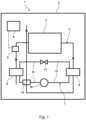
- FIG. 1 shows a schematic representation of an exemplary embodiment of a device 1 according to the invention for drying laundry.
- the device 1 has a device housing 2 in which an open process air system 3 with a drying chamber 4 (not shown) that accommodates laundry to be dried is arranged.
- the process air system 3 has a process air fan 5, which can be activated by means of control electronics 6 of the device 1 to carry out a drying process.
- the device 1 has a heat pump 7 which is thermally coupled to the process air system 3 and is designed as a compressor heat pump.
- the heat pump 7 has a condenser 8 that heats the ambient air entering the process air system 3, an evaporator 9 that cools and dehumidifies the process air exiting the drying chamber 4, a compressor 10, an expansion unit 11 and refrigerant lines 12 that connect these components of the heat pump 7 to one another, whereby a refrigerant circuit of the heat pump 7 is formed.
- the device 1 has a cooling unit 13 which is thermally coupled to a refrigerant line 12 between the compressor 10 and the condenser 8 of the heat pump 7 for cooling a refrigerant flowing through this refrigerant line 12 .
- the cooling unit 13 is arranged on the process air system 3 in such a way that it can be at least partially acted upon by process air emerging from the evaporator 9 .
Description
Die Erfindung betrifft ein Gerät zum Trocknen von Wäsche, aufweisend wenigstens ein offenes Prozessluftsystem mit wenigstens einer zu trocknende Wäsche aufnehmenden Trockenkammer, wenigstens eine thermisch an das Prozessluftsystem gekoppelte Wärmepumpe und wenigstens eine thermisch an eine Kältemittelleitung zwischen einen Verdichter und einen Verflüssiger der Wärmepumpe gekoppelte Kühleinheit zum Kühlen eines durch die Kältemittelleitung strömenden Kältemittels. Des Weiteren betrifft die Erfindung ein Verfahren zum Betreiben einer Wärmepumpe eines Geräts zum Trocknen von Wäsche, das wenigstens ein offenes Prozessluftsystem mit wenigstens einer zu trocknende Wäsche aufnehmenden Trockenkammer aufweist, wobei die Wärmepumpe thermisch an das Prozessluftsystem gekoppelt ist und ein aus einem Verdichter der Wärmepumpe ausströmendes Kältemittel mittels wenigstens einer Kühleinheit, die thermisch an eine das aus dem Verdichter ausströmende Kältemittel führende Kältemittelleitung gekoppelt ist, aktiv gekühlt wird.The invention relates to an appliance for drying laundry, having at least one open process air system with at least one drying chamber accommodating laundry to be dried, at least one heat pump thermally coupled to the process air system and at least one cooling unit thermally coupled to a refrigerant line between a compressor and a condenser of the heat pump Cooling a refrigerant flowing through the refrigerant line. Furthermore, the invention relates to a method for operating a heat pump of an appliance for drying laundry, which has at least one open process air system with at least one drying chamber accommodating laundry to be dried, the heat pump being thermally coupled to the process air system and a compressor of the heat pump flowing out Refrigerant is actively cooled by means of at least one cooling unit, which is thermally coupled to a refrigerant line that carries the refrigerant flowing out of the compressor.
Geräte zum Trocknen von Wäsche sind in vielfältigen Ausgestaltungen bekannt. Insbesondere sind Geräte zum Trocknen von Wäsche bekannt, die ein offenes Prozessluftsystem mit einer zu trocknende Wäsche aufnehmenden Trockenkammer und eine Rückgewinnung von Wärme aus der in dem Prozessluftsystem strömenden Prozessluft ermöglichen. Ein solches Gerät kann beispielsweise als Ablufttrockner mit Wärmerückgewinnung ausgebildet sein. Entsprechende Geräte sind beispielsweise aus
Da ein Ablufttrockner ein offenes Prozessluftsystem aufweist, wird mit dem Ablufttrockner im Gegensatz zu einem Kondensationstrockner mit einer geschlossenem Prozessluftführung und Wärmerückgewinnung neben der latenten auch sensible Wärme zurückgewonnen. Zusätzlich erhöht auch die über den Verflüssiger der Wärmepumpe in die Prozessluft eingebrachte Verdichterleistung die Trockengeschwindigkeit. Dadurch kann ein Ablufttrockner mit Wärmerückgewinnung trotz eines Kondensationswirkungsgrades kleiner 50% geringere Verbrauchswerte haben als ein Kondensationstrockner.Since an exhaust air dryer has an open process air system, the exhaust air dryer, in contrast to a condensation dryer with a closed process air duct and heat recovery, recovers both latent and sensible heat. In addition, the compressor capacity introduced into the process air via the condenser of the heat pump also increases the drying speed. As a result, an exhaust air dryer with heat recovery can have lower consumption values than a condensation dryer, despite a condensation efficiency of less than 50%.
In einem geschlossenen Prozessluftsystem führt die kontinuierlich eingebrachte Verdichterleistung zu einer zunehmenden Erwärmung des Kondensationstrockners. Steht dieser Leistungseintrag nicht im Gleichgewicht mit den während eines Trocknungsvorgangs gegebenen Energieverlusten, wie beispielsweise einer Bauteilerwärmung, Verlusten durch Wärmestrahlung, Konvektion oder Leckage, können das Prozessluftsystem und die Wärmepumpe überhitzen, wodurch die Effizienz der Wärmepumpe sinkt. Als Gegenmaßnahme hierzu sind Anwendungen mit aktiv gekühlten Zusatzwärmetauschern im Kältemittelkreislauf der Wärmepumpe oder mit Luft-Luft-Wärmetauschern in der Prozessluft bekannt.In a closed process air system, the continuously introduced compressor output leads to increasing heating of the condensation dryer. If this power input is not in balance with the energy losses occurring during a drying process, such as component heating, losses through thermal radiation, convection or leakage, the process air system and the heat pump can overheat, which reduces the efficiency of the heat pump. As a countermeasure to this, applications with actively cooled additional heat exchangers in the refrigerant circuit of the heat pump or with air-to-air heat exchangers in the process air are known.
Da in einem offenen Prozessluftsystem eines Ablufttrockners die Temperatur der angesaugten Prozessluft nahezu konstant bleibt und nicht höher als die Umgebungstemperatur ist, kommt es zu keiner entsprechenden Überhitzung. Das konstant niedrige Temperaturniveau der angesaugten Umgebungsluft bedingt hohe Wirkungsgrade der Wärmepumpe. Demgegenüber kann der Nachteil einer Gesamtenergiebilanz des Aufstellortes stehen, da die in der Regel wärmere Raumluft mehrmals durch kältere Außenluft ausgetauscht wird.
Der Kondensationswirkungsgrad von Ablufttrocknern mit einer Kompressor-Wärmepumpe zur Wärmerückgewinnung kann abhängig vom Pumpfaktor und der relativen Luftfeuchte der Eintrittsluft bis zu 70% betragen. Nur wenn die absoluten Wasserbeladungen der Prozessluft am Ein- und Austrittspunkt bei einer sonst verlustfreien Luftführung des Ablufttrockners gleich sind, kann dieser Wirkungsgrad unabhängig von dem Prozessluftvolumenstrom und der Trocknungsgeschwindigkeit 100% sein.The condensing efficiency of exhaust air dryers with a compressor heat pump for heat recovery can be up to 70% depending on the pumping factor and the relative humidity of the inlet air. This efficiency can only be 100% independent of the process air volume flow and the drying speed if the absolute water loading of the process air is the same at the entry and exit point with an otherwise loss-free air flow of the exhaust air dryer.
Da die aus dem Verdampfer der Wärmepumpe austretende Prozessluft den Ablufttrockner mit 100% relativer Feuchte verlässt, müsste bei einem angenommenen Prozessluftvolumenstrom von 200 m3/h die Prozessluft um 500 W abgekühlt werden. Beispielhaft für den angenommenen Prozessluftvolumenstrom in Höhe von 200 m3/h darf bei einer spezifischen Trocknungsgeschwindigkeit von 10 min/kg und einer Anfangsfeuchte der Wäsche von 60% die Differenz der Wasserbeladungen der Prozessluft zwischen Eintritt und Austritt des Prozessluftsystems für einen Kondensationsgrad von 80% 2,88 g/kg nicht überschreiten. Dieser Wert ist unabhängig von dem Zustand der Umgebungsluft.Since the process air exiting the evaporator of the heat pump leaves the exhaust air dryer with 100% relative humidity, the process air would have to be cooled by 500 W for an assumed process air volume flow of 200 m 3 /h. As an example for the assumed process air volume flow of 200 m 3 /h with a specific drying speed of 10 min/kg and an initial moisture content of the laundry of 60%, the difference in the water loading of the process air between the inlet and outlet of the process air system for a degree of condensation of 80% 2 .88 g/kg. This value is independent of the condition of the ambient air.
Würde die Prozessluft mit gleicher Enthalpie wie am Eintritt des Prozessluftsystems aus diesem austreten, wäre die Wasserbeladung der Prozessluft noch in demjenigen Bereich, dass der Kondensationswirkungsgrad größer als 80% wäre. Hätte die Prozessluft am Eintritt des Prozessluftsystems bei 20°C eine relative Luftfeuchte von nur 50%, wäre der Kondensationswirkungsgrad nur noch etwa 80%. Bei einer Lufttemperatur von 20°C mit 100% relativer Feuchte am Austritt des Prozessluftsystems wäre der Kondensationswirkungsgrad etwa 60%. Für den angenommene Luftvolumenstrom von 200 m3/h entspricht dies einem Energieeintrag in die Prozessluft von 1000 W. Für eine mittlere elektrische Anschlussleistung des Trockners von 900 W (Verdichterleistung, Antriebsleistung und Steuerung) abzüglich thermischer Verluste von etwa 1/3, kann die Kondensationswirkung daher 70% nicht überschreiten.If the process air exited the process air system with the same enthalpy as at the inlet, the water loading of the process air would still be in the range where the condensation efficiency would be greater than 80%. If the process air at the inlet of the process air system had a relative humidity of only 50% at 20°C, the condensation efficiency would only be around 80%. At an air temperature of 20°C with 100% relative humidity at the outlet of the process air system, the condensation efficiency would be around 60%. For the assumed air volume flow of 200 m 3 /h, this corresponds to an energy input of 1000 W into the process air. For an average electrical connected load of the dryer of 900 W (compressor power, drive power and control) minus thermal losses of around 1/3, the condensation effect therefore do not exceed 70%.
Um einen Wärmepumpentrockner in einem geschlossenen Raum als Kondensationstrockner mit einem Kondensationswirkungsgrad größer 80% betreiben zu können, wären thermische Verluste des Systems im Bereich der gesamten Anschlussleistung erforderlich. Verluste in dieser Größenordnung verlängern die Trocknungszeit und erhöhen gleichzeitig den Energieverbrauch in ungewollter Höhe.In order to be able to operate a heat pump dryer in a closed room as a condensation dryer with a condensation efficiency greater than 80%, thermal losses of the system would be required in the area of the total connected load. Losses of this magnitude prolong the drying time and at the same time increase the energy consumption to an unintended extent.
Eine Aufgabe der Erfindung ist es, den Energieinhalt von Prozessluft an einem Austritt eines offenen Prozessluftsystems eines Geräts zum Trocknen von Wäsche zu verringern und die Entfeuchtungsleistung des Geräts zu erhöhen.An object of the invention is to reduce the energy content of process air at an outlet of an open process air system of an appliance for drying laundry and to increase the dehumidification capacity of the appliance.
Diese Aufgabe wird durch die unabhängigen Patentansprüche gelöst. Vorteilhafte Ausgestaltungen sind in der nachfolgenden Beschreibung, den abhängigen Patentansprüchen und den Figuren wiedergegeben, wobei diese Ausgestaltungen jeweils für sich genommen oder in verschiedener Kombination von wenigstens zwei dieser Ausgestaltungen miteinander einen weiterbildenden, insbesondere auch bevorzugten oder vorteilhaften, Aspekt der Erfindung darstellen können. Ausgestaltungen des Geräts können dabei Ausgestaltungen des Verfahrens entsprechen, und umgekehrt, selbst wenn im Folgenden hierauf im Einzelfall nicht explizit hingewiesen wird.This object is solved by the independent patent claims. Advantageous configurations are presented in the following description, the dependent patent claims and the figures, whereby these configurations, taken individually or in various combinations of at least two of these configurations with one another, can represent a further developing, in particular also preferred or advantageous, aspect of the invention. Configurations of the device can correspond to configurations of the method and vice versa, even if this is not explicitly referred to in the following in individual cases.
Ein erfindungsgemäßes Gerät zum Trocknen von Wäsche weist wenigstens ein offenes Prozessluftsystem mit wenigstens einer zu trocknende Wäsche aufnehmenden Trockenkammer, wenigstens eine thermisch an das Prozessluftsystem gekoppelte Wärmepumpe und wenigstens eine thermisch an eine Kältemittelleitung zwischen einem Verdichter und einem Verflüssiger der Wärmepumpe gekoppelte Kühleinheit zum Kühlen eines durch die Kältemittelleitung strömenden Kältemittels auf, wobei die Kühleinheit derart an dem Prozessluftsystem angeordnet ist, dass sie zumindest teilweise mit einer aus dem Verdampfer austretenden Prozessluft beaufschlagbar ist.A device according to the invention for drying laundry has at least one open process air system with at least one drying chamber accommodating laundry to be dried, at least one heat pump thermally coupled to the process air system and at least one cooling unit thermally coupled to a refrigerant line between a compressor and a condenser of the heat pump for cooling a through refrigerant flowing up the refrigerant line, the cooling unit being arranged on the process air system in such a way that it can be at least partially acted upon by process air emerging from the evaporator.
Erfindungsgemäß wird das aus dem Verdichter ausströmende, dem Verflüssiger zuzuführende, verdichtete Kältemittel mittels der zusätzlichen Kühleinheit an der Kältemittelleitung des Kältemittelkreislaufs gekühlt. Hierzu kann die Kühleinheit wenigstens einen thermisch an die Kältemittelleitung gekoppelten, mit einem Kühlluftstrom beaufschlagbaren Luftkühler oder einen thermisch an die Kältemittelleitung gekoppelten, mit einem Kühlflüssigkeitsstrom beaufschlagbaren Flüssigkeitskühler aufweisen, also einen Wärmetauscher. Die Kältemittelleitung kann beispielsweise durch den Kühler hindurchgeführt oder an diesem vorbeigeführt sein.According to the invention, the compressed refrigerant flowing out of the compressor and to be fed to the condenser is cooled by means of the additional cooling unit on the refrigerant line of the refrigerant circuit. For this purpose, the cooling unit can have at least one air cooler thermally coupled to the refrigerant line and capable of being subjected to a flow of cooling air, or a liquid cooler thermally coupled to the refrigerant line and capable of being subjected to a flow of cooling liquid, ie a heat exchanger. The Refrigerant line can be routed through the cooler or past it, for example.
Im Kältemittelkreislauf führt die zusätzliche Kühleinheit zu einer Kühlung des Kältemittels vor seinem Eintritt in den Verflüssiger und somit insgesamt zu einer stärkeren bzw. sehr starken Unterkühlung des Kältemittels. Die mögliche Unterkühlung des Kältemittels im Verflüssiger bleibt davon unbeeinflusst. Die die Trocknungsgeschwindigkeit bestimmende Leistung des Verflüssigers sinkt zwar um den Leistungsaustrag der Kühleinheit, die Entfeuchtungsleistung über den Verdampfer der Wärmepumpe bleibt aber unverändert. Damit wird der Energieinhalt bzw. die Wasserbeladung der gesättigten Luft am Austritt des Verdampfers im Verhältnis zum Energieeintrag über den Verflüssiger so weit gesenkt, dass die Kondensationsrate um den gewünschten Betrag auf über 80% steigt. Aufgrund der konstanten Zustandsbedingungen der Prozessluft am Eintritt des Verflüssigers, aber wegen des durch die Kühleinheit bewirkten geringeren Leistungseintrags, sinkt die Trocknungsgeschwindigkeit. Der Zusatzkühler kann beispielsweise mehr als 600 W übertragen. Da mit der erfindungsgemäßen Maßnahme der verstärkten Unterkühlung des Kältemittels auch eine Verbesserung des Wirkungsgrads der Wärmepumpe verbunden ist, ist sogar die Senkung des Energieverbrauchs des Geräts für die Trocknung von Wäsche möglich. Durch die erfindungsgemäße Zusatzkühlung des Kältemittels des Kältemittelkreislaufs der Wärmepumpe und den dadurch realisierbaren Kondensationswirkungsgrad von mehr als 80% kann das erfindungsgemäße Gerät trotz seines offenen Prozessluftkreislaufs als Kondensationstrockner in einem geschlossenen Raum betrieben werden.In the refrigerant circuit, the additional cooling unit leads to cooling of the refrigerant before it enters the condenser and thus overall to stronger or very strong subcooling of the refrigerant. The possible supercooling of the refrigerant in the condenser remains unaffected. Although the performance of the condenser, which determines the drying speed, falls by the performance output of the cooling unit, the dehumidification performance via the evaporator of the heat pump remains unchanged. This reduces the energy content or the water load of the saturated air at the outlet of the evaporator in relation to the energy input via the condenser to such an extent that the condensation rate increases by the desired amount to over 80%. Due to the constant condition of the process air at the inlet of the condenser, but due to the lower power input caused by the cooling unit, the drying speed decreases. For example, the additional cooler can transmit more than 600 W. Since the measure according to the invention of increased supercooling of the refrigerant also improves the efficiency of the heat pump, it is even possible to reduce the energy consumption of the appliance for drying laundry. Due to the additional cooling of the refrigerant of the refrigerant circuit of the heat pump according to the invention and the condensing efficiency of more than 80% that can be achieved as a result, the device according to the invention can be operated as a condensation dryer in a closed room despite its open process air circuit.
Das offene Prozessluftsystem ist teilweise durch die zu trocknende Wäsche aufnehmende Trockenkammer gebildet und weist wenigstens ein Prozessluftgebläse zum Bewegen von Prozessluft durch kommunizierend mit der Trockenkammer verbundene Prozessluftführungen des Prozessluftsystems auf. Das Prozessluftsystem kann zudem wenigstens einen Prozessluftfilter aufweisen, der beispielsweise zwischen die Trockenkammer und den Verdampfer der Wärmepumpe geschaltet sein kann. Des Weiteren kann das Prozessluftsystem wenigstens eine elektrische Zusatzheizeinheit aufweisen, die zwischen den Verflüssiger der Wärmepumpe und der Trockenkammer geschaltet sein kann.The open process air system is partially formed by the drying chamber accommodating the laundry to be dried and has at least one process air fan for moving process air through process air ducts of the process air system connected in a communicating manner to the drying chamber. The process air system can also have at least one process air filter, which can be connected, for example, between the drying chamber and the evaporator of the heat pump. Furthermore, the process air system can have at least one additional electrical heating unit, which can be connected between the condenser of the heat pump and the drying chamber.
Die Wärmepumpe ist vorzugsweise unmittelbar thermisch an das Prozessluftsystem gekoppelt. Insbesondere sind der Verdampfer und der Verflüssiger thermisch an das Prozessluftsystem gekoppelt. Die Wärmepumpe kann als Kompressor-Wärmepumpe ausgebildet sein und entsprechend den Verdichter zum Verdichten des Kältemittels und eine Expansionseinheit zu Expandieren des Kältemittels aufweisen.The heat pump is preferably directly thermally coupled to the process air system. In particular, the evaporator and the condenser are thermally connected to the process air system coupled. The heat pump can be designed as a compressor heat pump and correspondingly have the compressor for compressing the refrigerant and an expansion unit for expanding the refrigerant.
Das Gerät zum Trocknen von Wäsche kann beispielsweise als Wäschetrockner (Ablufttrockner), als Waschtrockner mit einer Ablufttrockenfunktion oder als Trockenschrank mit einer Ablufttrockenfunktion ausgebildet sein.The appliance for drying laundry can be designed, for example, as a tumble dryer (air-vented dryer), as a washer-dryer with an air-vented drying function or as a drying cabinet with an air-vented drying function.
Durch die Anordnung der Kühleinheit derart an dem Prozessluftsystem, dass sie zumindest teilweise mit einer aus dem Verdampfer austretenden Prozessluft beaufschlagbar ist, ist kein Zusatzgebläse erforderlich, was mit Vorteilen bezüglich des verfügbaren Bauraums innerhalb des Geräts und mit einer Reduzierung von Herstellungskosten des Geräts verbunden ist. Die aus dem Verdampfer kommende gesättigte Prozessluft wird über die Kühleinheit geführt. Abhängig von dem jeweiligen Energieaustrag mittels der Kühleinheit aus dem Kältemittelkreislauf wird nicht nur die Temperatur der Prozessluft angehoben, sondern auch deren relative Feuchte gesenkt. Da die Temperatur der aus dem Prozessluftsystem austretenden Prozessluft durch die erfindungsgemäße Kühlmaßnahme dann deutlich über der Temperatur der in das Prozessluftsystem eintretenden Umgebungsluft liegt, ist niedergeschlagenes Kondensat, beispielsweise an mit der Prozessluft angeblasenen Wänden des Prozessluftsystems nicht mehr zu erwarten.By arranging the cooling unit on the process air system in such a way that it can be at least partially charged with process air emerging from the evaporator, no additional fan is required, which is associated with advantages in terms of the available installation space within the device and with a reduction in the manufacturing costs of the device. The saturated process air coming from the evaporator is routed through the cooling unit. Depending on the respective energy discharge by means of the cooling unit from the refrigerant circuit, not only is the temperature of the process air raised, but its relative humidity is also lowered. Since the temperature of the process air exiting the process air system is then significantly higher than the temperature of the ambient air entering the process air system due to the cooling measure according to the invention, precipitated condensate, for example on walls of the process air system blown with the process air, is no longer to be expected.
Nach einem erfindungsgemäßen Verfahren zum Betreiben einer Wärmepumpe eines Geräts zum Trocknen von Wäsche, das wenigstens ein offenes Prozessluftsystem mit wenigstens einer zu trocknende Wäsche aufnehmenden Trockenkammer aufweist, wobei die Wärmepumpe thermisch an das Prozessluftsystem gekoppelt ist, wird ein aus einem Verdichter der Wärmepumpe ausströmendes Kältemittel mittels wenigstens einer Kühleinheit, die thermisch an eine das aus dem Verdichter ausströmende Kältemittel führende Kältemittelleitung gekoppelt ist, aktiv gekühlt, wobei die Kühleinheit mit einer aus einem Verdampfer der Wärmepumpe austretenden Prozessluftstrom beaufschlagt wird.According to a method according to the invention for operating a heat pump of an appliance for drying laundry, which has at least one open process air system with at least one drying chamber accommodating laundry to be dried, with the heat pump being thermally coupled to the process air system, a refrigerant flowing out of a compressor of the heat pump is at least one cooling unit, which is thermally coupled to a refrigerant line carrying the refrigerant flowing out of the compressor, is actively cooled, wherein the cooling unit is acted upon by a process air flow emerging from an evaporator of the heat pump.
Mit dem Verfahren sind die oben mit Bezug auf das Gerät genannten Vorteile entsprechend verbunden. Insbesondere kann das Verfahren mit dem Gerät gemäß einer der oben genannten Ausgestaltungen oder einer beliebigen Kombination von wenigstens zwei dieser Ausgestaltungen miteinander durchgeführt werden. Die aktive Kühlung der Kühleinheit erfolgt durch eine Beaufschlagung der Kühleinheit mit einem Kühlfluidstrom.The advantages mentioned above in relation to the device are correspondingly associated with the method. In particular, the method with the device according to one of the above configurations or any combination of at least two of these configurations are carried out together. The cooling unit is actively cooled by applying a flow of cooling fluid to the cooling unit.
Gemäß der Erfindung wird die Kühleinheit mit einer aus einem Verdampfer der Wärmepumpe austretenden Prozessluftstrom beaufschlagt. Mit dieser Ausgestaltung sind die oben mit Bezug auf die entsprechende Ausgestaltung des Geräts genannten Vorteile entsprechend verbunden.According to the invention, the cooling unit is subjected to a flow of process air emerging from an evaporator of the heat pump. The advantages mentioned above in relation to the corresponding configuration of the device are correspondingly associated with this configuration.
Im Folgenden wird die Erfindung unter Bezugnahme auf die anliegenden Figuren anhand bevorzugter Ausführungsformen exemplarisch erläutert. Es zeigt:
- Fig. 1
- eine schematische Darstellung eines Ausführungsbeispiels für ein erfindungsgemäßes Gerät.
- 1
- a schematic representation of an embodiment of a device according to the invention.
Das Gerät 1 weist ein Gerätegehäuse 2 auf, in dem ein offenes Prozessluftsystem 3 mit einer nicht gezeigten, zu trocknende Wäsche aufnehmenden Trockenkammer 4 angeordnet ist. Das Prozessluftsystem 3 weist ein Prozessluftgebläse 5 auf, das mittels einer Ansteuerelektronik 6 des Geräts 1 zur Durchführung eines Trocknungsvorgangs aktiviert werden kann.The device 1 has a
Des Weiteren weist das Gerät 1 eine thermisch an das Prozessluftsystem 3 gekoppelte Wärmepumpe 7 auf, die als Kompressor-Wärmepumpe ausgebildet ist. Die Wärmepumpe 7 weist einen die in das Prozessluftsystem 3 eintretende Umgebungsluft erwärmenden Verflüssiger 8, einen die aus der Trockenkammer 4 austretende Prozessluft kühlenden und entfeuchtenden Verdampfer 9, einen Verdichter 10, eine Expansionseinheit 11 und diese Komponenten der Wärmepumpe 7 miteinander verbindende Kältemittelleitungen 12 auf, wodurch ein Kältemittelkreislauf der Wärmepumpe 7 ausgebildet wird.Furthermore, the device 1 has a
Ferner weist das Gerät 1 eine thermisch an eine Kältemittelleitung 12 zwischen dem Verdichter 10 und dem Verflüssiger 8 der Wärmepumpe 7 gekoppelte Kühleinheit 13 zum Kühlen eines durch diese Kältemittelleitung 12 strömenden Kältemittels auf. Die Kühleinheit 13 ist derart an dem Prozessluftsystem 3 angeordnet, dass sie zumindest teilweise mit einer aus dem Verdampfer 9 austretenden Prozessluft beaufschlagbar ist.Furthermore, the device 1 has a
- 11
- GerätDevice
- 22
- Gerätegehäusedevice housing
- 33
- Prozessluftsystemprocess air system
- 44
- Trockenkammerdrying chamber
- 55
- Prozessluftgebläseprocess air blower
- 66
- Ansteuerelektronikcontrol electronics
- 77
- Wärmepumpeheat pump
- 88th
- Verflüssigercondenser
- 99
- VerdampferEvaporator
- 1010
- Verdichtercompressor
- 1111
- Expansionseinheitexpansion unit
- 1212
- Kältemittelleitungrefrigerant line
- 1313
- Kühleinheitcooling unit
Claims (2)
- Appliance (1) for drying laundry, having at least one open process air system (3) with at least one drying chamber (4) for receiving laundry to be dried, at least one heat pump (7) thermally coupled to the process air system (3), and at least one cooling unit (13) thermally coupled to a refrigerant line (12) between a compressor (10) and a condenser (8) of the heat pump (7) for cooling a refrigerant flowing through the refrigerant line (12), characterised in that the cooling unit (13) is arranged on the process air system (3) such that process air emerging from the evaporator (9) can be applied to it at least partially.
- Method for operating a heat pump (7) of an appliance (1) for drying laundry, which has at least one open process air system (3) with at least one drying chamber (4) for receiving laundry to be dried, wherein the heat pump (7) is thermally coupled to the process air system (3) and a refrigerant is actively cooled, which refrigerant flows from a compressor (10) of the heat pump (7) by means of at least one cooling unit (13), which is thermally coupled to a refrigerant line (12) which carries coolant flowing from the compressor (10), characterised in that a process air flow emerging from an evaporator (9) of the heat pump (7) is applied to the cooling unit (13).
Applications Claiming Priority (1)
| Application Number | Priority Date | Filing Date | Title |
|---|---|---|---|
| DE102019207225.9A DE102019207225A1 (en) | 2019-05-17 | 2019-05-17 | Apparatus for drying laundry and a method for operating a heat pump of such an apparatus |
Publications (2)
| Publication Number | Publication Date |
|---|---|
| EP3739110A1 EP3739110A1 (en) | 2020-11-18 |
| EP3739110B1 true EP3739110B1 (en) | 2023-08-02 |
Family
ID=70553987
Family Applications (1)
| Application Number | Title | Priority Date | Filing Date |
|---|---|---|---|
| EP20173145.2A Active EP3739110B1 (en) | 2019-05-17 | 2020-05-06 | Device for drying laundry and method for operating a heat pump of such a device |
Country Status (3)
| Country | Link |
|---|---|
| EP (1) | EP3739110B1 (en) |
| DE (1) | DE102019207225A1 (en) |
| PL (1) | PL3739110T3 (en) |
Family Cites Families (16)
| Publication number | Priority date | Publication date | Assignee | Title |
|---|---|---|---|---|
| DE3000865A1 (en) * | 1980-01-11 | 1981-07-16 | Fichtel & Sachs Ag, 8720 Schweinfurt | Clothes dryer - has heat exchanger before heater to increase efficiency |
| DE4409607C2 (en) * | 1993-04-21 | 2002-03-14 | Miele & Cie | Condensation clothes dryer with a heat pump |
| DE19731826A1 (en) * | 1997-07-24 | 1998-02-12 | Joachim Rieder | Laundry dryer for sensitive fabrics |
| DE19737075A1 (en) * | 1997-08-26 | 1998-03-19 | Joachim Rieder | Laundry dryer |
| JP4026469B2 (en) * | 2002-10-16 | 2007-12-26 | 松下電器産業株式会社 | Clothes dryer |
| DE10349712B4 (en) * | 2003-10-23 | 2007-03-01 | Miele & Cie. Kg | Method for drying laundry and tumble dryer for performing the method |
| JP4531414B2 (en) * | 2004-02-16 | 2010-08-25 | パナソニック株式会社 | Washing and drying machine |
| KR100925739B1 (en) * | 2007-09-13 | 2009-11-11 | 엘지전자 주식회사 | Ductless dryer |
| EP2058427A1 (en) * | 2007-11-06 | 2009-05-13 | BSH Electrodomésticos España, S.A. | Household appliance having a heat pump unit and means for cooling a component thereof |
| ES2385767B1 (en) * | 2009-04-15 | 2013-06-17 | Bsh Electrodomesticos España S.A. | Blender as well as heat pump and domestic appliance with such a blender. |
| ES2373135B1 (en) * | 2009-12-14 | 2012-12-13 | Bsh Electrodomesticos España S.A | DOMESTIC APPLIANCE THAT INCLUDES AN EXPANSION SYSTEM. |
| DE102009055206A1 (en) * | 2009-12-22 | 2011-06-30 | BSH Bosch und Siemens Hausgeräte GmbH, 81739 | Domestic appliance with heat pump cycle |
| EP2550390B1 (en) * | 2010-08-09 | 2016-10-05 | LG Electronics Inc. | Clothes dryer |
| EP2599912A1 (en) * | 2011-11-30 | 2013-06-05 | Electrolux Home Products Corporation N.V. | Heat pump laundry drying appliance |
| DE102017217767A1 (en) * | 2017-10-06 | 2019-04-11 | BSH Hausgeräte GmbH | Laundry treatment apparatus and method for operating a laundry treatment appliance |
| DE102018201257A1 (en) * | 2018-01-29 | 2019-08-01 | BSH Hausgeräte GmbH | Apparatus for drying laundry and method for operating a heat pump of such apparatus |
-
2019
- 2019-05-17 DE DE102019207225.9A patent/DE102019207225A1/en active Pending
-
2020
- 2020-05-06 PL PL20173145.2T patent/PL3739110T3/en unknown
- 2020-05-06 EP EP20173145.2A patent/EP3739110B1/en active Active
Also Published As
| Publication number | Publication date |
|---|---|
| PL3739110T3 (en) | 2024-01-03 |
| CN111945401A (en) | 2020-11-17 |
| EP3739110A1 (en) | 2020-11-18 |
| DE102019207225A1 (en) | 2020-11-19 |
Similar Documents
| Publication | Publication Date | Title |
|---|---|---|
| EP2034084B1 (en) | Clothes drier with auxiliary heat exchanger | |
| DE19638865C2 (en) | Condensation clothes dryer with a heat pump device | |
| EP2732090B1 (en) | Vented laundry drying having an additional heater and heat exchanger unit | |
| DE4306217A1 (en) | Program-controlled laundry drier with a heat-pump circuit | |
| DE102013111491B4 (en) | Clothing dryer and operating method of a clothes dryer | |
| DE4434205A1 (en) | Laundry dryer with laundry drum | |
| DE102005041145A1 (en) | Laundry dryer, has heat pump heating system comprising compressor with changeable output, and controller controlling and/or regulating output of compressor based on residual moisture in laundry that is to be dried | |
| EP1884586A2 (en) | Laundry dryer with supplementary heat exchanger | |
| DE2161649A1 (en) | dryer | |
| WO2007074040A1 (en) | Household appliance for doing laundry | |
| EP2194182A1 (en) | Dryer with a heat pump and an electrical heater and method for operating same | |
| EP2227585A1 (en) | Washing/drying device comprising a moisture determining device and method for operating a washing/drying device | |
| DE102006042991A1 (en) | Apparatus and method for drying laundry with a heat pump and a heat exchanger | |
| EP3517680B1 (en) | Device for drying of laundry and procedure for operating a heat pump for such a device | |
| DE102009052484B4 (en) | Heat pump cycle device | |
| EP3392396A1 (en) | Drum dryer with room air drying function | |
| DE4306215A1 (en) | Program-controlled laundry drier with a heat-pump circuit | |
| EP2041359A1 (en) | Domestic device for the care of laundry items and method for passing cooling air into such a device | |
| DE102012212159A1 (en) | Front loading exhaust air laundry drying apparatus e.g. exhaust air washer-dryer, has recovery aggregate for transferring heat from channel to passage and designed as heat pump that comprises vaporizer, condenser, compressor and valve | |
| EP3739110B1 (en) | Device for drying laundry and method for operating a heat pump of such a device | |
| DE19853234A1 (en) | Tumble dryer with a heat pump | |
| EP1205592B1 (en) | Laundry dryer cabinet | |
| DE102011079449A1 (en) | Method of operating a heat pump dryer | |
| EP3759274B1 (en) | Appliance for drying laundry | |
| DE3543722A1 (en) | Laundry drier |
Legal Events
| Date | Code | Title | Description |
|---|---|---|---|
| PUAI | Public reference made under article 153(3) epc to a published international application that has entered the european phase |
Free format text: ORIGINAL CODE: 0009012 |
|
| STAA | Information on the status of an ep patent application or granted ep patent |
Free format text: STATUS: THE APPLICATION HAS BEEN PUBLISHED |
|
| AK | Designated contracting states |
Kind code of ref document: A1 Designated state(s): AL AT BE BG CH CY CZ DE DK EE ES FI FR GB GR HR HU IE IS IT LI LT LU LV MC MK MT NL NO PL PT RO RS SE SI SK SM TR |
|
| AX | Request for extension of the european patent |
Extension state: BA ME |
|
| STAA | Information on the status of an ep patent application or granted ep patent |
Free format text: STATUS: REQUEST FOR EXAMINATION WAS MADE |
|
| 17P | Request for examination filed |
Effective date: 20210518 |
|
| RBV | Designated contracting states (corrected) |
Designated state(s): AL AT BE BG CH CY CZ DE DK EE ES FI FR GB GR HR HU IE IS IT LI LT LU LV MC MK MT NL NO PL PT RO RS SE SI SK SM TR |
|
| GRAP | Despatch of communication of intention to grant a patent |
Free format text: ORIGINAL CODE: EPIDOSNIGR1 |
|
| STAA | Information on the status of an ep patent application or granted ep patent |
Free format text: STATUS: GRANT OF PATENT IS INTENDED |
|
| RIC1 | Information provided on ipc code assigned before grant |
Ipc: D06F 58/24 20060101ALN20230224BHEP Ipc: D06F 58/02 20060101ALN20230224BHEP Ipc: D06F 58/48 20200101ALI20230224BHEP Ipc: D06F 58/20 20060101AFI20230224BHEP |
|
| INTG | Intention to grant announced |
Effective date: 20230314 |
|
| GRAS | Grant fee paid |
Free format text: ORIGINAL CODE: EPIDOSNIGR3 |
|
| GRAA | (expected) grant |
Free format text: ORIGINAL CODE: 0009210 |
|
| STAA | Information on the status of an ep patent application or granted ep patent |
Free format text: STATUS: THE PATENT HAS BEEN GRANTED |
|
| AK | Designated contracting states |
Kind code of ref document: B1 Designated state(s): AL AT BE BG CH CY CZ DE DK EE ES FI FR GB GR HR HU IE IS IT LI LT LU LV MC MK MT NL NO PL PT RO RS SE SI SK SM TR |
|
| REG | Reference to a national code |
Ref country code: GB Ref legal event code: FG4D Free format text: NOT ENGLISH |
|
| REG | Reference to a national code |
Ref country code: CH Ref legal event code: EP |
|
| REG | Reference to a national code |
Ref country code: DE Ref legal event code: R096 Ref document number: 502020004445 Country of ref document: DE |
|
| REG | Reference to a national code |
Ref country code: IE Ref legal event code: FG4D Free format text: LANGUAGE OF EP DOCUMENT: GERMAN |
|
| REG | Reference to a national code |
Ref country code: LT Ref legal event code: MG9D |
|
| REG | Reference to a national code |
Ref country code: NL Ref legal event code: MP Effective date: 20230802 |
|
| PG25 | Lapsed in a contracting state [announced via postgrant information from national office to epo] |
Ref country code: GR Free format text: LAPSE BECAUSE OF FAILURE TO SUBMIT A TRANSLATION OF THE DESCRIPTION OR TO PAY THE FEE WITHIN THE PRESCRIBED TIME-LIMIT Effective date: 20231103 |
|
| PG25 | Lapsed in a contracting state [announced via postgrant information from national office to epo] |
Ref country code: IS Free format text: LAPSE BECAUSE OF FAILURE TO SUBMIT A TRANSLATION OF THE DESCRIPTION OR TO PAY THE FEE WITHIN THE PRESCRIBED TIME-LIMIT Effective date: 20231202 |
|
| PG25 | Lapsed in a contracting state [announced via postgrant information from national office to epo] |
Ref country code: SE Free format text: LAPSE BECAUSE OF FAILURE TO SUBMIT A TRANSLATION OF THE DESCRIPTION OR TO PAY THE FEE WITHIN THE PRESCRIBED TIME-LIMIT Effective date: 20230802 Ref country code: RS Free format text: LAPSE BECAUSE OF FAILURE TO SUBMIT A TRANSLATION OF THE DESCRIPTION OR TO PAY THE FEE WITHIN THE PRESCRIBED TIME-LIMIT Effective date: 20230802 Ref country code: PT Free format text: LAPSE BECAUSE OF FAILURE TO SUBMIT A TRANSLATION OF THE DESCRIPTION OR TO PAY THE FEE WITHIN THE PRESCRIBED TIME-LIMIT Effective date: 20231204 Ref country code: NO Free format text: LAPSE BECAUSE OF FAILURE TO SUBMIT A TRANSLATION OF THE DESCRIPTION OR TO PAY THE FEE WITHIN THE PRESCRIBED TIME-LIMIT Effective date: 20231102 Ref country code: NL Free format text: LAPSE BECAUSE OF FAILURE TO SUBMIT A TRANSLATION OF THE DESCRIPTION OR TO PAY THE FEE WITHIN THE PRESCRIBED TIME-LIMIT Effective date: 20230802 Ref country code: LV Free format text: LAPSE BECAUSE OF FAILURE TO SUBMIT A TRANSLATION OF THE DESCRIPTION OR TO PAY THE FEE WITHIN THE PRESCRIBED TIME-LIMIT Effective date: 20230802 Ref country code: LT Free format text: LAPSE BECAUSE OF FAILURE TO SUBMIT A TRANSLATION OF THE DESCRIPTION OR TO PAY THE FEE WITHIN THE PRESCRIBED TIME-LIMIT Effective date: 20230802 Ref country code: IS Free format text: LAPSE BECAUSE OF FAILURE TO SUBMIT A TRANSLATION OF THE DESCRIPTION OR TO PAY THE FEE WITHIN THE PRESCRIBED TIME-LIMIT Effective date: 20231202 Ref country code: HR Free format text: LAPSE BECAUSE OF FAILURE TO SUBMIT A TRANSLATION OF THE DESCRIPTION OR TO PAY THE FEE WITHIN THE PRESCRIBED TIME-LIMIT Effective date: 20230802 Ref country code: GR Free format text: LAPSE BECAUSE OF FAILURE TO SUBMIT A TRANSLATION OF THE DESCRIPTION OR TO PAY THE FEE WITHIN THE PRESCRIBED TIME-LIMIT Effective date: 20231103 Ref country code: FI Free format text: LAPSE BECAUSE OF FAILURE TO SUBMIT A TRANSLATION OF THE DESCRIPTION OR TO PAY THE FEE WITHIN THE PRESCRIBED TIME-LIMIT Effective date: 20230802 |