EP3738844B1 - Drive unit - Google Patents
Drive unit Download PDFInfo
- Publication number
- EP3738844B1 EP3738844B1 EP20173418.3A EP20173418A EP3738844B1 EP 3738844 B1 EP3738844 B1 EP 3738844B1 EP 20173418 A EP20173418 A EP 20173418A EP 3738844 B1 EP3738844 B1 EP 3738844B1
- Authority
- EP
- European Patent Office
- Prior art keywords
- motor
- controller
- control
- torque
- drive unit
- Prior art date
- Legal status (The legal status is an assumption and is not a legal conclusion. Google has not performed a legal analysis and makes no representation as to the accuracy of the status listed.)
- Active
Links
- 230000001172 regenerating effect Effects 0.000 claims description 5
- 230000009467 reduction Effects 0.000 claims description 4
- 230000037361 pathway Effects 0.000 description 56
- 239000012530 fluid Substances 0.000 description 35
- 238000001816 cooling Methods 0.000 description 33
- 239000003638 chemical reducing agent Substances 0.000 description 20
- 230000002093 peripheral effect Effects 0.000 description 19
- 230000007246 mechanism Effects 0.000 description 10
- 230000017525 heat dissipation Effects 0.000 description 7
- 238000000034 method Methods 0.000 description 7
- 230000001276 controlling effect Effects 0.000 description 6
- 230000004048 modification Effects 0.000 description 6
- 238000012986 modification Methods 0.000 description 6
- 238000010586 diagram Methods 0.000 description 5
- 239000002783 friction material Substances 0.000 description 5
- 238000002485 combustion reaction Methods 0.000 description 3
- FYYHWMGAXLPEAU-UHFFFAOYSA-N Magnesium Chemical compound [Mg] FYYHWMGAXLPEAU-UHFFFAOYSA-N 0.000 description 2
- 230000009471 action Effects 0.000 description 2
- XAGFODPZIPBFFR-UHFFFAOYSA-N aluminium Chemical compound [Al] XAGFODPZIPBFFR-UHFFFAOYSA-N 0.000 description 2
- 229910052782 aluminium Inorganic materials 0.000 description 2
- 230000005540 biological transmission Effects 0.000 description 2
- 239000010720 hydraulic oil Substances 0.000 description 2
- 229910052749 magnesium Inorganic materials 0.000 description 2
- 239000011777 magnesium Substances 0.000 description 2
- 239000000463 material Substances 0.000 description 2
- 238000004804 winding Methods 0.000 description 2
- RYGMFSIKBFXOCR-UHFFFAOYSA-N Copper Chemical compound [Cu] RYGMFSIKBFXOCR-UHFFFAOYSA-N 0.000 description 1
- 230000003213 activating effect Effects 0.000 description 1
- 230000008867 communication pathway Effects 0.000 description 1
- 229910052802 copper Inorganic materials 0.000 description 1
- 239000010949 copper Substances 0.000 description 1
- 230000001419 dependent effect Effects 0.000 description 1
- 230000000881 depressing effect Effects 0.000 description 1
- 230000000994 depressogenic effect Effects 0.000 description 1
- 238000009434 installation Methods 0.000 description 1
- 230000001105 regulatory effect Effects 0.000 description 1
- 239000007787 solid Substances 0.000 description 1
Images


Classifications
-
- B—PERFORMING OPERATIONS; TRANSPORTING
- B60—VEHICLES IN GENERAL
- B60T—VEHICLE BRAKE CONTROL SYSTEMS OR PARTS THEREOF; BRAKE CONTROL SYSTEMS OR PARTS THEREOF, IN GENERAL; ARRANGEMENT OF BRAKING ELEMENTS ON VEHICLES IN GENERAL; PORTABLE DEVICES FOR PREVENTING UNWANTED MOVEMENT OF VEHICLES; VEHICLE MODIFICATIONS TO FACILITATE COOLING OF BRAKES
- B60T7/00—Brake-action initiating means
- B60T7/12—Brake-action initiating means for automatic initiation; for initiation not subject to will of driver or passenger
- B60T7/122—Brake-action initiating means for automatic initiation; for initiation not subject to will of driver or passenger for locking of reverse movement
-
- B—PERFORMING OPERATIONS; TRANSPORTING
- B60—VEHICLES IN GENERAL
- B60L—PROPULSION OF ELECTRICALLY-PROPELLED VEHICLES; SUPPLYING ELECTRIC POWER FOR AUXILIARY EQUIPMENT OF ELECTRICALLY-PROPELLED VEHICLES; ELECTRODYNAMIC BRAKE SYSTEMS FOR VEHICLES IN GENERAL; MAGNETIC SUSPENSION OR LEVITATION FOR VEHICLES; MONITORING OPERATING VARIABLES OF ELECTRICALLY-PROPELLED VEHICLES; ELECTRIC SAFETY DEVICES FOR ELECTRICALLY-PROPELLED VEHICLES
- B60L15/00—Methods, circuits, or devices for controlling the traction-motor speed of electrically-propelled vehicles
- B60L15/20—Methods, circuits, or devices for controlling the traction-motor speed of electrically-propelled vehicles for control of the vehicle or its driving motor to achieve a desired performance, e.g. speed, torque, programmed variation of speed
- B60L15/2072—Methods, circuits, or devices for controlling the traction-motor speed of electrically-propelled vehicles for control of the vehicle or its driving motor to achieve a desired performance, e.g. speed, torque, programmed variation of speed for drive off
- B60L15/2081—Methods, circuits, or devices for controlling the traction-motor speed of electrically-propelled vehicles for control of the vehicle or its driving motor to achieve a desired performance, e.g. speed, torque, programmed variation of speed for drive off for drive off on a slope
-
- B—PERFORMING OPERATIONS; TRANSPORTING
- B60—VEHICLES IN GENERAL
- B60L—PROPULSION OF ELECTRICALLY-PROPELLED VEHICLES; SUPPLYING ELECTRIC POWER FOR AUXILIARY EQUIPMENT OF ELECTRICALLY-PROPELLED VEHICLES; ELECTRODYNAMIC BRAKE SYSTEMS FOR VEHICLES IN GENERAL; MAGNETIC SUSPENSION OR LEVITATION FOR VEHICLES; MONITORING OPERATING VARIABLES OF ELECTRICALLY-PROPELLED VEHICLES; ELECTRIC SAFETY DEVICES FOR ELECTRICALLY-PROPELLED VEHICLES
- B60L15/00—Methods, circuits, or devices for controlling the traction-motor speed of electrically-propelled vehicles
- B60L15/20—Methods, circuits, or devices for controlling the traction-motor speed of electrically-propelled vehicles for control of the vehicle or its driving motor to achieve a desired performance, e.g. speed, torque, programmed variation of speed
- B60L15/2009—Methods, circuits, or devices for controlling the traction-motor speed of electrically-propelled vehicles for control of the vehicle or its driving motor to achieve a desired performance, e.g. speed, torque, programmed variation of speed for braking
- B60L15/2018—Methods, circuits, or devices for controlling the traction-motor speed of electrically-propelled vehicles for control of the vehicle or its driving motor to achieve a desired performance, e.g. speed, torque, programmed variation of speed for braking for braking on a slope
-
- B—PERFORMING OPERATIONS; TRANSPORTING
- B60—VEHICLES IN GENERAL
- B60T—VEHICLE BRAKE CONTROL SYSTEMS OR PARTS THEREOF; BRAKE CONTROL SYSTEMS OR PARTS THEREOF, IN GENERAL; ARRANGEMENT OF BRAKING ELEMENTS ON VEHICLES IN GENERAL; PORTABLE DEVICES FOR PREVENTING UNWANTED MOVEMENT OF VEHICLES; VEHICLE MODIFICATIONS TO FACILITATE COOLING OF BRAKES
- B60T2201/00—Particular use of vehicle brake systems; Special systems using also the brakes; Special software modules within the brake system controller
- B60T2201/06—Hill holder; Start aid systems on inclined road
-
- Y—GENERAL TAGGING OF NEW TECHNOLOGICAL DEVELOPMENTS; GENERAL TAGGING OF CROSS-SECTIONAL TECHNOLOGIES SPANNING OVER SEVERAL SECTIONS OF THE IPC; TECHNICAL SUBJECTS COVERED BY FORMER USPC CROSS-REFERENCE ART COLLECTIONS [XRACs] AND DIGESTS
- Y02—TECHNOLOGIES OR APPLICATIONS FOR MITIGATION OR ADAPTATION AGAINST CLIMATE CHANGE
- Y02T—CLIMATE CHANGE MITIGATION TECHNOLOGIES RELATED TO TRANSPORTATION
- Y02T10/00—Road transport of goods or passengers
- Y02T10/60—Other road transportation technologies with climate change mitigation effect
- Y02T10/72—Electric energy management in electromobility
Definitions
- the present invention relates to a drive unit.
- EP 2 757 005 A2 discloses a method for holding a vehicle on a slope.
- the vehicle has a drive unit with an internal combustion engine, a clutch connected to the engine, a gear assembly connected to the clutch and driving at least one wheel, a control unit and an electric motor connected and connectable to an input of the gear unit.
- DE 100 65 589 A1 discloses a drive unit for a car with an internal combustion unit and a hill-holder system controlling the operation of a clutch of the drive unit.
- EP 1 547 891 A1 discloses an electric car having six wheels each driven by a separate electric motor and a braking device. A computer controls the resistance of the electric motors in dependence from the position of a braking pedal.
- WO 2015/0568024 A1 discloses a control apparatus for a vehicle having an idle stop function.
- the vehicle has an internal combustion engine and a torque converter.
- DE 101 04 498 A1 discloses a method for activating a start-up function for a vehicle starting on a slope. The function is activated by an enlarged braking force on a braking pedal.
- a drive unit includes an electric motor, a torque converter, a brake sensor and a controller.
- the torque converter is a device to which a torque outputted from the motor is inputted.
- the brake sensor detects a braking operation amount.
- the controller executes a first control of controlling the torque outputted from the motor based on the braking operation amount.
- the drive unit includes the torque converter to which the torque, outputted from the motor, is inputted.
- the motor can be kept rotated. Because of this, when the controller controls the output of the motor based on the braking operation amount, the motor can be kept rotated during stop of the vehicle on a slope. Therefore, when braking is released in starting movement on the slope, the vehicle can smoothly start moving without moving backward.
- the drive unit further includes an accelerator sensor detecting an accelerator opening degree. Besides, the controller executes the first control when the accelerator opening degree is 0%.
- the controller executes a second control when the accelerator opening degree is greater than 0%.
- the second control is executed by the controller to stop the first control and control the torque outputted from the motor based on the accelerator opening degree.
- the drive unit further includes a vehicle velocity sensor detecting a vehicle velocity.
- the controller executes a third control when the accelerator opening degree is 0% and simultaneously the vehicle velocity is greater than a first threshold.
- the third control is executed by the controller to either control the torque outputted from the motor or execute a regenerative control such that the vehicle velocity becomes less than or equal to the first threshold.
- the drive unit further includes a vehicle velocity sensor detecting a vehicle velocity.
- the controller executes the first control when the vehicle velocity is less than or equal to a first threshold.
- the controller controls the torque outputted from the motor such that the torque increases with reduction in the braking operation amount in executing the first control.
- the controller makes zero the torque outputted from the motor when the braking operation amount is greater than or equal to a second threshold in executing the first control.
- FIG. 1 is a schematic diagram of the drive unit according to the present preferred embodiment
- FIG. 2 is a cross-sectional view of the drive unit according to the present preferred embodiment.
- axial direction refers to an extending direction of a rotational axis O of a motor 2 and a torque converter 3.
- the term “circumferential direction” refers to a circumferential direction of an imaginary circle about the rotational axis O
- the term “radial direction” refers to a radial direction of the imaginary circle about the rotational axis O.
- forward rotation refers to rotation in forward movement of a vehicle
- reverse rotation refers to rotation in backward movement of the vehicle.
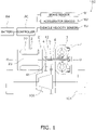
- a drive unit 100 includes the motor 2, the torque converter 3, a controller 80, a brake sensor 81, an accelerator sensor 82, a vehicle velocity sensor 83 and a battery 84. Besides, the drive unit 100 further includes a reducer 4, an input shaft 5, an output shaft 6, a torque converter casing 7, a hydraulic fluid sump 91 and a first cooling flow pathway 9a.
- the drive unit 100 is installed in an electric car. The drive unit 100 transmits a torque, outputted from the motor 2, to drive wheels 101. It should be noted that the torque converter 3, the torque converter casing 7, the hydraulic fluid sump 91 and the first cooling flow pathway 9a will be collectively referred to as a torque converter unit.
- the motor 2 includes a prime mover casing 21, a stator 22 and a rotor 23.
- the motor 2 is a so-called inner rotor motor.
- the prime mover casing 21 is fixed to a vehicle body frame or so forth and is non-rotatable.
- the stator 22 is fixed to the inner peripheral surface of the prime mover casing 21.
- the stator 22 is non-rotatable.
- the rotor 23 is rotated about the rotational axis O.
- the rotor 23 is disposed radially inside the stator 22.
- the torque converter 3 is disposed at an interval from the motor 2 in the axial direction.
- the reducer 4 is disposed between the torque converter 3 and the motor 2.
- the rotational axis O of the torque converter 3 is substantially matched with that of the motor 2.
- the torque converter 3 is a device to which the torque, outputted from the motor 2, is inputted. Additionally, the torque converter 3 amplifies the torque inputted thereto from the motor 2, and outputs the amplified torque to the reducer 4.
- the torque converter 3 includes a cover 31, an impeller 32, a turbine 33, a stator 34, a first one-way clutch 35 and a second one-way clutch 36. Besides, the torque converter 3 further includes a centrifugal clutch 37.
- the torque converter 3 is disposed such that the impeller 32 faces the motor 2 (the left side in FIG. 3 ) whereas the cover 31 faces opposite to the motor 2 (the right side in FIG. 3 ).
- the torque converter 3 is accommodated in the interior of the torque converter casing 7. Hydraulic fluid is supplied to the interior of the torque converter 3.
- the hydraulic fluid is, for instance, hydraulic oil.
- the cover 31 is a component to which the torque, outputted from the motor 2, is inputted.
- the cover 31 is rotated by the torque inputted thereto from the motor 2.
- the cover 31 is fixed to the input shaft 5 extending from the motor 2.
- the cover 31 includes a spline hole to which the input shaft 5 is spline-coupled. Because of this, the cover 31 is unitarily rotated with the input shaft 5.
- the cover 31 is disposed to cover the turbine 33.
- the cover 31 includes a disc portion 311, a cylindrical portion 312 and a cover hub 313.
- the disc portion 311 includes an opening in the middle thereof.
- the cylindrical portion 312 extends from the outer peripheral end of the disc portion 311 toward the motor 2.
- the disc portion 311 and the cylindrical portion 312 are provided as a single member.
- the cover hub 313 is fixed to the inner peripheral end of the disc portion 311.
- the cover hub 313 is provided as a member separated from the disc portion 311.
- the cover hub 313 may be provided together with the disc portion 311 as a single member.
- the cover hub 313 includes a first boss portion 313a, a first flange portion 313b and a protruding portion 313c.
- the first boss portion 313a, the first flange portion 313b and the protruding portion 313c are provided as a single member.
- the first boss portion 313a is made in the shape of a cylinder including a spline hole.
- the input shaft 5 is spline-coupled to the first boss portion 313a.
- the first boss portion 313a is rotatably supported by the torque converter casing 7 through a bearing member 102. Because of this, the first boss portion 313a axially extends from the first flange portion 313b to the opposite side of the motor 2.
- the first flange portion 313b extends radially outward from the first boss portion 313a. Specifically, the first flange portion 313b extends radially outward from the motor 2-side end of the first boss portion 313a.
- the disc portion 311 is fixed to the outer peripheral end of the first flange portion 313b.
- the protruding portion 313c axially extends from the first flange portion 313b.
- the protruding portion 313c extends toward the motor 2.
- the protruding portion 313c extends from the outer peripheral end of the first flange portion 313b.
- the protruding portion 313c has a cylindrical shape.
- the protruding portion 313c includes a plurality of through holes 313d. The hydraulic fluid is discharged from the torque converter 3 through the through holes 313d.
- the impeller 32 is rotated unitarily with the cover 31.
- the impeller 32 is fixed to the cover 31.
- the impeller 32 includes an impeller shell 321, a plurality of impeller blades 322, an impeller hub 323 and a plurality of supply flow pathways 324.
- the impeller shell 321 is fixed to the cover 31.
- the plural impeller blades 322 are attached to the inner surface of the impeller shell 321.
- the impeller hub 323 is attached to the inner peripheral end of the impeller shell 321. It should be noted that in the present preferred embodiment, the impeller hub 323 is provided together with the impeller shell 321 as a single member but may be provided as a member separated from the impeller shell 321.
- the impeller hub 323 includes a second boss portion 323a and a second flange portion 323b.
- the second boss portion 323a has a cylindrical shape and axially extends.
- the second boss portion 323a is rotatably supported by the torque converter casing 7 through a bearing member 103 (see FIG. 2 ).
- a stationary shaft 104 axially extends in the interior of the second boss portion 323a.
- the stationary shaft 104 has a cylindrical shape and the output shaft 6 axially extends in the interior of the stationary shaft 104.
- the stationary shaft 104 extends from, for instance, a reducer casing 42 or the torque converter casing 7.
- the stationary shaft 104 is non-rotatable.
- the supply flow pathways 324 are provided in the impeller hub 323. Detailedly, the supply flow pathways 324 are provided in the second flange portion 323b. The supply flow pathways 324 extend radially outward from the inner peripheral surface of the impeller hub 323. Additionally, the supply flow pathways 324 are opened to the interior of a torus T. It should be noted that the torus T is a space enclosed by the impeller 32 and the turbine 33.
- the supply flow pathways 324 are axially closed. In other words, the supply flow pathways 324 are through holes radially extending in the impeller hub 323. As shown in FIG. 4 , the supply flow pathways 324 extend in a radial shape. The supply flow pathways 324 slant opposite to a forward rotational direction, while extending radially outward. In other words, the supply flow pathways 324 slant in a reverse rotational direction (counterclockwise in FIG. 4 ), while extending radially outward. It should be noted that the extending shape of each supply flow pathway 324 is not limited to a straight shape. For example, as shown in FIG. 5 , each supply flow pathway 324 may extend in a curved shape.
- the turbine 33 is disposed in opposition to the impeller 32. Specifically, the turbine 33 is axially opposed to the impeller 32. The turbine 33 is a component to which a torque is transmitted from the impeller 32 through the hydraulic fluid.
- the turbine 33 includes a turbine shell 331, a plurality of turbine blades 332 and a turbine hub 333.
- the turbine blades 332 are fixed to the inner surface of the turbine shell 331.
- the turbine hub 333 is fixed to the inner peripheral end of the turbine shell 331.
- the turbine hub 333 is fixed to the turbine shell 331 by at least one rivet.
- the turbine hub 333 is provided as a member separated from the turbine shell 331.
- the turbine hub 333 may be provided together with the turbine shell 331 as a single member.
- the output shaft 6 is attached to the turbine hub 333. Detailedly, the output shaft 6 is spline-coupled to the turbine hub 333. The turbine hub 333 is unitarily rotated with the output shaft 6.
- the turbine hub 333 includes a third boss portion 333a and a third flange portion 333b.
- the third boss portion 333a and the third flange portion 333b are provided as a single member.
- the third boss portion 333a has a cylindrical shape and includes a spline hole.
- the output shaft 6 is spline-coupled to the third boss portion 333a.
- the third boss portion 333a axially extends from the third flange portion 333b to the opposite side of the motor 2. In other words, the third boss portion 333a axially extends from the third flange portion 333b toward the cover hub 313.
- the third boss portion 333a is disposed at a radial interval from the protruding portion 313c.
- the protruding portion 313c is disposed radially outside the third boss portion 333a.
- the first one-way clutch 35 is disposed between the third boss portion 333a and the protruding portion 313c. It should be noted that without installation of the first one-way clutch 35, the outer peripheral surface of the third boss portion 333a and the inner peripheral surface of the protruding portion 313c are opposed to each other.
- a flow pathway is provided between the cover hub 313 and the distal end of the third boss portion 333a such that the hydraulic fluid flows therethrough.
- the third boss portion 333a is provided with a plurality of cutouts 333c on the distal end thereof. The cutouts 333c radially extend on the distal end of the third boss portion 333a. The hydraulic fluid is discharged from the torque converter 3 through the cutouts 333c and the through holes 313d.
- the third flange portion 333b extends radially outward from the third boss portion 333a. Detailedly, the third flange portion 333b extends radially outward from the motor 2-side end of the third boss portion 333a.
- the turbine shell 331 is fixed to the outer peripheral end of the third flange portion 333b by the at least one rivet or so forth.
- the stator 34 is configured to regulate the flow of the hydraulic fluid (hydraulic oil) returning from the turbine 33 to the impeller 32.
- the stator 34 is rotatable about the rotational axis O.
- the stator 34 is supported by the stationary shaft 104 through the second one-way clutch 36.
- the stator 34 is disposed axially between the impeller 32 and the turbine 33.
- the stator 34 includes a stator carrier 341 having a disc shape and a plurality of stator blades 342 attached to the outer peripheral surface of the stator carrier 341.
- the first one-way clutch 35 is disposed between the cover 31 and the turbine 33.
- the first one-way clutch 35 makes the cover 31 rotatable relative to the turbine 33 in the forward rotational direction.
- the first one-way clutch 35 is configured such that the cover 31 is rotated relative to the turbine 33. Because of this, in forward movement of the vehicle, the first one-way clutch 35 does not transmit a torque from the cover 31 to the turbine 33.
- the first one-way clutch 35 makes the cover 31 rotate unitarily with the turbine 33 in the reverse rotational direction.
- the first one-way clutch 35 is configured such that the cover 31 is rotated unitarily with the turbine 33. Because of this, in backward movement of the vehicle, the first one-way clutch 35 transmits a torque from the cover 31 to the turbine 33.
- the second one-way clutch 36 is disposed between the stationary shaft 104 and the stator 34.
- the second one-way clutch 36 is configured to make the stator 34 rotatable in the forward rotational direction.
- the second one-way clutch 36 makes the stator 34 non-rotatable in the reverse rotational direction. The torque is transmitted from the impeller 32 to the turbine 33, while being amplified by the stator 34.
- the centrifugal clutch 37 is attached to the turbine 33.
- the centrifugal clutch 37 is unitarily rotated with the turbine 33.
- the centrifugal clutch 37 is configured to couple the cover 31 and the turbine 33 to each other by a centrifugal force generated in rotation of the turbine 33.
- the centrifugal clutch 37 is configured to transmit the torque from the cover 31 to the turbine 33 when the rotational speed of the turbine 33 becomes greater than or equal to a predetermined value.
- the centrifugal clutch 37 includes a plurality of centrifugal elements 371 and a plurality of friction materials 372.
- the friction materials 372 are attached to the outer peripheral surfaces of the centrifugal elements 371, respectively.
- the centrifugal elements 371 are disposed while being radially movable. It should be noted that the centrifugal elements 371 are disposed while being circumferentially immovable. Because of this, the centrifugal elements 371 are rotated together with the turbine 33 and are moved radially outward by centrifugal forces.
- the centrifugal clutch 37 When the rotational speed of the turbine 33 becomes greater than or equal to the predetermined value, the centrifugal clutch 37 is configured such that the centrifugal elements 371 are moved radially outward and the friction materials 372 are engaged by friction with the inner peripheral surface of the cylindrical portion 312 of the cover 31. As a result, the centrifugal clutch 37 is turned to an on state, and the torque inputted to the cover 31 is transmitted therefrom to the turbine 33 through the centrifugal clutch 37. It should be noted that even when the centrifugal clutch 37 is turned to the on state, the hydraulic fluid is capable of flowing through the centrifugal clutch 37.
- the centrifugal elements 371 are moved radially inward, whereby the friction materials 372 and the inner peripheral surface of the cylindrical portion 312 of the cover 31, engaged by friction, are disengaged from each other.
- the centrifugal clutch 37 is turned to an off state, and the torque inputted to the cover 31 is not transmitted therefrom to the turbine 33 through the centrifugal clutch 37.
- the torque inputted to the cover 31 is transmitted therefrom to the impeller 32, and is then transmitted to the turbine 33 through the hydraulic fluid.
- the reducer 4 is disposed axially between the motor 2 and the torque converter 3.
- the reducer 4 transmits a torque, inputted thereto from the torque converter 3, to the drive wheel 101 side.
- the reducer 4 amplifies the torque inputted thereto from the torque converter 3 and transmits the amplified torque to the drive wheel 101 side through a differential gear 109.
- the reducer 4 includes a plurality of gears 41 and the reducer casing 42 accommodating the respective gears 41.
- one of the plural gears 41 is fixed to the output shaft 6.
- one of the gears 41 is provided together with the output shaft 6 as a single member.
- the input shaft 5 extends from the motor 2.
- the input shaft 5 extends toward the torque converter 3.
- the rotational axis of the input shaft 5 is substantially matched with that of the motor 2 and that of the torque converter 3.
- the input shaft 5 inputs the torque, outputted from the motor 2, to the torque converter 3.
- the input shaft 5 is attached at the distal end thereof to the cover hub 313 of the torque converter 3.
- the input shaft 5 is unitarily rotated with the rotor 23 of the motor 2.
- the input shaft 5 extends through the interior of the output shaft 6.
- the input shaft 5 is solid.
- the input shaft 5 includes a communicating pathway 51 in the distal end thereof.
- the communicating pathway 51 extends in the axial direction. Besides, the communicating pathway 51 is opened toward the first cooling flow pathway 9a.
- the output shaft 6 outputs the torque inputted thereto from the torque converter 3.
- the output shaft 6 outputs the torque, inputted thereto from the torque converter 3, to the reducer 4.
- the output shaft 6 extends from the torque converter 3 toward the motor 2.
- the output shaft 6 has a cylindrical shape.
- the input shaft 5 extends through the interior of the output shaft 6.
- the output shaft 6 is attached at one end (the right end in FIG. 2 ) to the turbine 33 of the torque converter 3.
- the output shaft 6 is rotatably supported at the other end (the left end in FIG. 2 ) by the reducer casing 42 through a bearing member 105.
- the torque converter casing 7 accommodates the torque converter 3.
- the torque converter casing 7 is provided together with the reducer casing 42 as a single member.
- the torque converter casing 7 may be provided as a member separated from the reducer casing 42.
- the torque converter casing 7 includes a side wall portion 71, an outer wall portion 72 and a plurality of heat dissipation fins 73.
- the sidewall portion 71 is disposed in opposition to the cover 31 of the torque converter 3.
- the sidewall portion 71 is disposed orthogonal to the rotational axis O.
- the torque converter 3 is disposed on one axial side (the left side in FIG. 6 ) of the sidewall portion 71.
- the sidewall portion 71 makes contact at the other side (the right lateral surface in FIG. 6 ) with external air.
- a member, functioning as a heat source is not disposed on the other side of the sidewall portion 71.
- the cover 31 is rotatably attached to the middle part of the sidewall portion 71 through the bearing member 102.
- the sidewall portion 71 is made of a material, having a high specific heat and a high thermal conductivity, so as to quickly absorb a large amount of heat from the hydraulic fluid flowing through the first cooling flow pathway 9a and release the absorbed heat to the atmosphere.
- the sidewall portion 71 is made of magnesium, aluminum or so forth.
- the outer wall portion 72 is disposed in opposition to the outer peripheral surface of the torque converter 3.
- the outer wall portion 72 is provided together with the sidewall portion 71 as a single member. However, the outer wall portion 72 may be provided as a member separated from the sidewall portion 71.
- the outer wall portion 72 extends toward the motor 2 from the outer peripheral end of the sidewall portion 71.
- the outer wall portion 72 extends substantially in parallel to the rotational axis O. It should be noted that the distal end (the motor 2-side end) of the outer wall portion 72 slants radially inward.
- the outer wall portion 72 can be made of a similar material to the sidewall portion 71.
- the heat dissipation fins 73 are provided on the sidewall portion 71.
- the heat dissipation fins 73 extend from the sidewall portion 71 to the opposite side (rightward in FIG. 6 ) of the torque converter 3.
- the heat dissipation fins 73 are attached to the sidewall portion 71 in order to efficiently dissipate the heat of the hydraulic fluid flowing through the first cooling flow pathway 9a.
- the thermal conductivity of the heat dissipation fins 73 is preferably set to be equivalent to or higher than that of the sidewall portion 71 but is not particularly limited to this setting.
- the heat dissipation fins 73 are made of, for instance, magnesium, aluminum, copper or so forth.
- the first cooling flow pathway 9a is a flow pathway for cooling the hydraulic fluid discharged from the torque converter 3.
- the first cooling flow pathway 9a extends in the interior of the torque converter casing 7.
- the first cooling flow pathway 9a is provided only in the upper half of the torque converter casing 7 (see FIG. 2 ).
- the first cooling flow pathway 9a extends from the middle part to the outer peripheral part in the interior of the sidewall portion 71 and axially extends therefrom beyond the torque converter 3 in the interior of the outer wall portion 72.
- the first cooling flow pathway 9a is communicated with the hydraulic fluid sump 91.
- the first cooling flow pathway 9a includes a plurality of paths in the interior of the sidewall portion 71.
- the first cooling flow pathway 9a is divided into two paths in the interior of the sidewall portion 71.
- the first cooling flow pathway 9a extends from the middle part to the outer peripheral part not in a straight shape but in a winding shape.
- the first cooling flow pathway 9a may include a plurality of paths in the interior of the outer wall portion 72 as well. In the present preferred embodiment, the first cooling flow pathway 9a is divided into, for instance, three paths in the interior of the outer wall portion 72. The first cooling flow pathway 9a axially extends in a straight shape in the interior of the outer wall portion 72. Alternatively, the first cooling flow pathway 9a may extend in a winding shape in the interior of the outer wall portion 72.
- the hydraulic fluid sump 91 is disposed to axially interpose the torque converter 3 together with the sidewall portion 71 therebetween.
- the hydraulic fluid sump 91, the torque converter 3 and the sidewall portion 71 are axially aligned in this order.
- the hydraulic fluid sump 91 is disposed in the interior of the reducer casing 42.
- the hydraulic fluid sump 91 is disposed above the rotational axis O.
- the hydraulic fluid sump 91 contains the hydraulic fluid to be supplied to the torque converter 3 in the interior thereof.
- the hydraulic fluid sump 91 is provided with a supply port 92 in the bottom surface thereof.
- the hydraulic fluid, discharged from the supply port 92, is supplied to the torque converter 3 through a flow pathway 106 provided between the stationary shaft 104 and the second boss portion 323a of the impeller hub 323.
- a centrifugal force is generated in rotation of the impeller 32 of the torque converter 3, whereby the hydraulic fluid residing in the interior of the flow pathway 106 is supplied to the interior of the torus T through the supply flow pathways 324. Then, the hydraulic fluid, discharged from the torque converter 3, flows to the first cooling flow pathway 9a through the communicating pathway 51. Subsequently, the hydraulic fluid, cooled while flowing through the first cooling flow pathway 9a, is returned to the hydraulic fluid sump 91.
- the brake sensor 81, the accelerator sensor 82 and the vehicle velocity sensor 83 are connected to the controller 80 by wired or wireless means such that information is communicable therebetween.
- the brake sensor 81 is configured to detect a braking operation amount.
- the brake sensor 81 is configured to detect the amount of stroke of a brake pedal, a tread force or so forth.
- the brake sensor 81 outputs the detected braking operation amount to the controller 80.
- the accelerator sensor 82 is configured to detect an accelerator opening degree.
- the accelerator sensor 82 outputs the detected accelerator opening degree to the controller 80.
- the vehicle velocity sensor 83 is configured to detect the velocity of a vehicle in which the drive unit 100 is installed.
- the vehicle velocity sensor 83 outputs the detected vehicle velocity to the controller 80.
- the controller 80 is configured to control a torque outputted from the motor 2.
- the controller 80 includes an ECU (Electronic Control Unit), a PCU (Power Control Unit) and so forth.
- the controller 80 causes the motor 2 and the battery 84 to transmit and receive electric power therebetween through an inverter circuit and a converter circuit, both of which are included in the PCU.
- the controller 80 is capable of controlling the torque outputted from the motor 2 by controlling the electric power outputted from the battery 84.
- the controller 80 executes first, second and third controls. For example, the controller 80 determines which of the first, second and third controls should be executed based on the accelerator opening degree and the vehicle velocity. More specifically, the controller 80 determines whether or not the accelerator opening degree is greater than 0%. When the accelerator opening degree is 0%, i.e., when the accelerator is not being operated, the controller 80 executes the first or third control. On the other hand, when the accelerator opening degree is greater than 0%, i.e., when the accelerator is being operated, the controller 80 executes the second control.
- the controller 80 executes the first control.
- the first threshold albeit not limited to a specific value, is set to be, for instance, 10 km/h.
- the controller 80 executes the first control.
- the controller 80 executes the third control.
- the controller 80 executes the third control.
- the controller 80 controls the torque outputted from the motor 2 based on the braking operation amount. Specifically, the controller 80 obtains the braking operation amount from the brake sensor 81. Then, the controller 80 determines whether or not the braking operation amount is greater than or equal to a second threshold.
- the controller 80 When determining that the braking operation amount is greater than or equal to the second threshold, the controller 80 makes zero the torque outputted from the motor 2. In other words, the controller 80 stops the motor 2. On the other hand, when determining that the braking operation amount is less than the second threshold, the controller 80 drives the motor 2. For example, the controller 80 drives the motor 2 such that the torque outputted from the motor 2 increases with reduction in braking operation amount.
- the controller 80 stops the first control and controls the torque outputted from the motor 2 based on the accelerator opening degree. In other words, when executing the second control, the controller 80 controls the torque outputted from the motor 2 based on the accelerator opening degree regardless of the braking operation amount.
- the controller 80 When executing the third control, the controller 80 either controls the torque outputted from the motor 2 or executes regenerative control such that the vehicle velocity becomes less than or equal to the first threshold. For example, the controller 80 decelerates the vehicle such that the vehicle velocity becomes less than or equal to the first threshold by regulating the regenerative amount of the motor 2.
- the controller 80 determines whether or not an accelerator pedal is being operated (step S1). Specifically, the controller 80 determines whether or not the accelerator pedal is being operated based on the accelerator opening degree detected by the accelerator sensor 82. When determining that the accelerator opening degree is greater than 0% (Yes in step S1), the controller 80 executes the second control (step S4).
- step S2 determines whether or not the vehicle velocity is less than or equal to the first threshold. Specifically, the controller 80 determines whether or not the vehicle velocity detected by the vehicle velocity sensor 83 is less than or equal to the first threshold. When determining that the vehicle velocity is less than or equal to the first threshold (Yes in step S2), the controller 80 executes the first control (step S3). On the other hand, when determining that the vehicle velocity is greater than the first threshold (No in step S2), the controller 80 executes the third control (step S5).
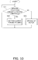
- step S11 when executing the first control, the controller 80 determines whether or not the braking operation amount is greater than or equal to the second threshold (step S11). When determining that the braking operation amount is greater than or equal to the second threshold (Yes in step S11), the controller 80 makes zero the torque outputted from the motor 2. In other words, the controller 80 stops the motor 2 (step S12).
- the controller 80 drives the motor 2 (step S13). Specifically, the controller 80 increases the torque outputted from the motor 2 with reduction in braking operation amount.
- the following action is enabled when a vehicle starts moving on a slope.
- the braking operation amount is greater than or equal to the second threshold. Because of this, the controller 80 makes zero the torque outputted from the motor 2, whereby the motor 2 is being stopped.
- the brake pedal is gradually depressed when the vehicle starts moving, whereby the braking operation amount is gradually reduced.
- the controller 80 gradually increases the torque outputted from the motor 2. It should be noted that the brake pedal is not being completely released, and hence, the vehicle is kept stopped by a braking force applied by friction braking and so forth.
- the vehicle is enabled to smoothly start moving on the slope without moving backward, because the motor 2 has been already driven.
- the motor 2 is being driven by the controller 80 while the vehicle is being stopped.
- the motor 2, when driven, can be herein rotated even while the vehicle is being stopped, because the drive unit 100 according to the present preferred embodiment includes the torque converter 3. Because of this, motor 2 can be inhibited from generating heat.
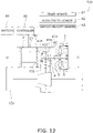
- the torque converter unit may further include a second cooling flow pathway 9b.
- the second cooling flow pathway 9b extends through the interior of a compartment 107 of a vehicle into which the torque converter unit is installed.
- the hydraulic fluid, discharged from the torque converter 3 flows through the second cooling flow pathway 9b.
- the hydraulic fluid, flowing through the second cooling flow pathway 9b, is cooled while dissipating heat thereof into the compartment 107.
- the hydraulic fluid is supplied to the second cooling flow pathway 9b from the communicating pathway 51. Additionally, the hydraulic fluid is returned to the hydraulic fluid sump 91 through the second cooling flow pathway 9b.
- the torque converter unit further includes a selector mechanism 11.
- the selector mechanism 11 is configured to select either the first cooling flow pathway 9a or the second cooling flow pathway 9b as a cooling flow pathway for supplying the hydraulic fluid discharged from the torque converter 3.
- the torque converter 3 may further include a plurality of elastic members 38.
- the elastic members 38 are disposed circumferentially between the first one-way clutch 35 and the cover 31.
- the elastic members 38 transmit a torque applied in the reverse rotational direction from the cover 31 to the first one-way clutch 35. It should be noted that, when the cover 31 is rotated with respect to the first one-way clutch 35 by more than a predetermined angle in the reverse rotational direction, first stopper surfaces 314 of the cover 31 make contact with second stopper surfaces 351 of the first one-way clutch 35. As a result, the torque, applied from the cover 31, is directly transmitted to the first one-way clutch 35.
- the elastic members 38 may be disposed circumferentially between the first one-way clutch 35 and the turbine 33. In this case, the elastic members 38 transmit a torque, applied from the first one-way clutch 35 in the reverse rotational direction, to the turbine 33.
- the present power transmission mechanism may include a planetary gear mechanism 400 and a clutch 401.
- the planetary gear mechanism 400 includes a sun gear 402, a plurality of planet gears 403, a planet carrier 404 and a ring gear 405.
- the sun gear 402 is attached to the input shaft 5.
- the sun gear 402 is unitarily rotated with the input shaft 5.
- the planet carrier 404 is attached to the output shaft 6.
- the planet carrier 404 is unitarily rotated with the output shaft 6.
- the clutch 401 is disposed between a non-rotatable member (e.g., the reducer casing 42 or the prime mover casing 21) and the ring gear 405. Besides, the clutch 401 is configured to brake rotation of the ring gear 405.
- a non-rotatable member e.g., the reducer casing 42 or the prime mover casing 21
- the clutch 401 is configured to brake rotation of the ring gear 405.
- the clutch 401 is, for instance, a one-way clutch.
- the clutch 401 makes the ring gear 405 rotatable in forward rotation of the input shaft 5 and the output shaft 6.
- the clutch 401 makes the ring gear 405 non-rotatable in reverse rotation of the input shaft 5 and the output shaft 6.
Landscapes
- Engineering & Computer Science (AREA)
- Transportation (AREA)
- Mechanical Engineering (AREA)
- Power Engineering (AREA)
- Electric Propulsion And Braking For Vehicles (AREA)
Description
- The present invention relates to a drive unit.
-
EP 2 757 005 A2DE 100 65 589 A1EP 1 547 891 A1 discloses an electric car having six wheels each driven by a separate electric motor and a braking device. A computer controls the resistance of the electric motors in dependence from the position of a braking pedal.WO 2015/0568024 A1 DE 101 04 498 A1 discloses a method for activating a start-up function for a vehicle starting on a slope. The function is activated by an enlarged braking force on a braking pedal. - In recent years, there have been developed a variety of electric cars traveling with use of a motor as a drive source. In the electric cars, drive wheels are driven by the motor. Such electric cars as herein described execute a control of reducing the vehicle velocity thereof with use of friction braking and regenerative braking when a braking operation is performed (e.g.,
Japan Laid-open Patent Application Publication No. 2017-139839 - It is an object of the present invention to prevent a vehicle driven by an electric motor from moving backward in starting movement on a slope. This object is achieved by a drive unit having the features of enclosed claim 1. Advantageous embodiments of the invention form the subject-matter of the dependent claims.
- A drive unit according to an aspect of the present invention includes an electric motor, a torque converter, a brake sensor and a controller. The torque converter is a device to which a torque outputted from the motor is inputted. The brake sensor detects a braking operation amount. The controller executes a first control of controlling the torque outputted from the motor based on the braking operation amount.
- According to the configuration, the drive unit includes the torque converter to which the torque, outputted from the motor, is inputted. Hence, even during stop of a vehicle, the motor can be kept rotated. Because of this, when the controller controls the output of the motor based on the braking operation amount, the motor can be kept rotated during stop of the vehicle on a slope. Therefore, when braking is released in starting movement on the slope, the vehicle can smoothly start moving without moving backward.
- Preferably, the drive unit further includes an accelerator sensor detecting an accelerator opening degree. Besides, the controller executes the first control when the accelerator opening degree is 0%.
- Preferably, the controller executes a second control when the accelerator opening degree is greater than 0%. The second control is executed by the controller to stop the first control and control the torque outputted from the motor based on the accelerator opening degree.
- Preferably, the drive unit further includes a vehicle velocity sensor detecting a vehicle velocity. Besides, the controller executes a third control when the accelerator opening degree is 0% and simultaneously the vehicle velocity is greater than a first threshold. The third control is executed by the controller to either control the torque outputted from the motor or execute a regenerative control such that the vehicle velocity becomes less than or equal to the first threshold.
- Preferably, the drive unit further includes a vehicle velocity sensor detecting a vehicle velocity. Besides, the controller executes the first control when the vehicle velocity is less than or equal to a first threshold.
- Preferably, the controller controls the torque outputted from the motor such that the torque increases with reduction in the braking operation amount in executing the first control.
- Preferably, the controller makes zero the torque outputted from the motor when the braking operation amount is greater than or equal to a second threshold in executing the first control.
- Overall, according to the present invention, it is possible to prevent a vehicle from moving backward in starting movement on a slope.
-
-
FIG. 1 is a schematic diagram of a drive unit. -
FIG. 2 is a cross-sectional view of the drive unit. -
FIG. 3 is a cross-sectional view of a torque converter. -
FIG. 4 is a cross-sectional view of a type of impeller hub. -
FIG. 5 is a cross-sectional view of another type of impeller hub. -
FIG. 6 is a cross-sectional view of the drive unit shown for indicating a first cooling flow pathway. -
FIG. 7 is a cross-sectional view of a sidewall portion of a type of cover. -
FIG. 8 is a cross-sectional view of a sidewall portion of another type of cover. -
FIG. 9 is a flowchart showing a method of controlling a controller. -
FIG. 10 is a flowchart showing a method of controlling the controller. -
FIG. 11 is a schematic diagram of a drive unit according to a modification. -
FIG. 12 is a schematic diagram of a first one-way clutch according to another modification. -
FIG. 13 is a schematic diagram of a drive unit according to yet another modification. - A preferred embodiment of a drive unit according to the present invention will be hereinafter explained with reference to drawings.
FIG. 1 is a schematic diagram of the drive unit according to the present preferred embodiment, whereasFIG. 2 is a cross-sectional view of the drive unit according to the present preferred embodiment. It should be noted that in the following explanation, the term "axial direction" refers to an extending direction of a rotational axis O of amotor 2 and atorque converter 3. On the other hand, the term "circumferential direction" refers to a circumferential direction of an imaginary circle about the rotational axis O, whereas the term "radial direction" refers to a radial direction of the imaginary circle about the rotational axis O. Moreover, the term "forward rotation" refers to rotation in forward movement of a vehicle, whereas the term "reverse rotation" refers to rotation in backward movement of the vehicle. - As shown in
FIGS. 1 and2 , adrive unit 100 includes themotor 2, thetorque converter 3, acontroller 80, abrake sensor 81, anaccelerator sensor 82, avehicle velocity sensor 83 and abattery 84. Besides, thedrive unit 100 further includes areducer 4, aninput shaft 5, anoutput shaft 6, atorque converter casing 7, ahydraulic fluid sump 91 and a firstcooling flow pathway 9a. Thedrive unit 100 is installed in an electric car. Thedrive unit 100 transmits a torque, outputted from themotor 2, to drivewheels 101. It should be noted that thetorque converter 3, thetorque converter casing 7, thehydraulic fluid sump 91 and the firstcooling flow pathway 9a will be collectively referred to as a torque converter unit. - The
motor 2 includes a prime mover casing 21, astator 22 and arotor 23. In the present preferred embodiment, themotor 2 is a so-called inner rotor motor. The prime mover casing 21 is fixed to a vehicle body frame or so forth and is non-rotatable. - The
stator 22 is fixed to the inner peripheral surface of theprime mover casing 21. Thestator 22 is non-rotatable. Therotor 23 is rotated about the rotational axis O. Therotor 23 is disposed radially inside thestator 22. - The
torque converter 3 is disposed at an interval from themotor 2 in the axial direction. Thereducer 4 is disposed between thetorque converter 3 and themotor 2. The rotational axis O of thetorque converter 3 is substantially matched with that of themotor 2. Thetorque converter 3 is a device to which the torque, outputted from themotor 2, is inputted. Additionally, thetorque converter 3 amplifies the torque inputted thereto from themotor 2, and outputs the amplified torque to thereducer 4. - As shown in
FIG. 3 , thetorque converter 3 includes acover 31, animpeller 32, aturbine 33, astator 34, a first one-way clutch 35 and a second one-way clutch 36. Besides, thetorque converter 3 further includes acentrifugal clutch 37. - The
torque converter 3 is disposed such that theimpeller 32 faces the motor 2 (the left side inFIG. 3 ) whereas thecover 31 faces opposite to the motor 2 (the right side inFIG. 3 ). Thetorque converter 3 is accommodated in the interior of thetorque converter casing 7. Hydraulic fluid is supplied to the interior of thetorque converter 3. The hydraulic fluid is, for instance, hydraulic oil. - The
cover 31 is a component to which the torque, outputted from themotor 2, is inputted. Thecover 31 is rotated by the torque inputted thereto from themotor 2. Thecover 31 is fixed to theinput shaft 5 extending from themotor 2. For example, thecover 31 includes a spline hole to which theinput shaft 5 is spline-coupled. Because of this, thecover 31 is unitarily rotated with theinput shaft 5. Thecover 31 is disposed to cover theturbine 33. - The
cover 31 includes adisc portion 311, acylindrical portion 312 and acover hub 313. Thedisc portion 311 includes an opening in the middle thereof. Thecylindrical portion 312 extends from the outer peripheral end of thedisc portion 311 toward themotor 2. Thedisc portion 311 and thecylindrical portion 312 are provided as a single member. - The
cover hub 313 is fixed to the inner peripheral end of thedisc portion 311. In the present preferred embodiment, thecover hub 313 is provided as a member separated from thedisc portion 311. However, thecover hub 313 may be provided together with thedisc portion 311 as a single member. - The
cover hub 313 includes afirst boss portion 313a, afirst flange portion 313b and a protrudingportion 313c. Thefirst boss portion 313a, thefirst flange portion 313b and the protrudingportion 313c are provided as a single member. - The
first boss portion 313a is made in the shape of a cylinder including a spline hole. Theinput shaft 5 is spline-coupled to thefirst boss portion 313a. As shown inFIG. 2 , thefirst boss portion 313a is rotatably supported by thetorque converter casing 7 through a bearingmember 102. Because of this, thefirst boss portion 313a axially extends from thefirst flange portion 313b to the opposite side of themotor 2. - As shown in
FIG. 3 , thefirst flange portion 313b extends radially outward from thefirst boss portion 313a. Detailedly, thefirst flange portion 313b extends radially outward from the motor 2-side end of thefirst boss portion 313a. Thedisc portion 311 is fixed to the outer peripheral end of thefirst flange portion 313b. - The protruding
portion 313c axially extends from thefirst flange portion 313b. The protrudingportion 313c extends toward themotor 2. The protrudingportion 313c extends from the outer peripheral end of thefirst flange portion 313b. The protrudingportion 313c has a cylindrical shape. The protrudingportion 313c includes a plurality of throughholes 313d. The hydraulic fluid is discharged from thetorque converter 3 through the throughholes 313d. - The
impeller 32 is rotated unitarily with thecover 31. Theimpeller 32 is fixed to thecover 31. Theimpeller 32 includes animpeller shell 321, a plurality ofimpeller blades 322, animpeller hub 323 and a plurality ofsupply flow pathways 324. - The
impeller shell 321 is fixed to thecover 31. Theplural impeller blades 322 are attached to the inner surface of theimpeller shell 321. - The
impeller hub 323 is attached to the inner peripheral end of theimpeller shell 321. It should be noted that in the present preferred embodiment, theimpeller hub 323 is provided together with theimpeller shell 321 as a single member but may be provided as a member separated from theimpeller shell 321. - The
impeller hub 323 includes asecond boss portion 323a and asecond flange portion 323b. Thesecond boss portion 323a has a cylindrical shape and axially extends. Thesecond boss portion 323a is rotatably supported by thetorque converter casing 7 through a bearing member 103 (seeFIG. 2 ). Astationary shaft 104 axially extends in the interior of thesecond boss portion 323a. It should be noted that thestationary shaft 104 has a cylindrical shape and theoutput shaft 6 axially extends in the interior of thestationary shaft 104. Besides, thestationary shaft 104 extends from, for instance, areducer casing 42 or thetorque converter casing 7. Thestationary shaft 104 is non-rotatable. - The
supply flow pathways 324 are provided in theimpeller hub 323. Detailedly, thesupply flow pathways 324 are provided in thesecond flange portion 323b. Thesupply flow pathways 324 extend radially outward from the inner peripheral surface of theimpeller hub 323. Additionally, thesupply flow pathways 324 are opened to the interior of a torus T. It should be noted that the torus T is a space enclosed by theimpeller 32 and theturbine 33. - The
supply flow pathways 324 are axially closed. In other words, thesupply flow pathways 324 are through holes radially extending in theimpeller hub 323. As shown inFIG. 4 , thesupply flow pathways 324 extend in a radial shape. Thesupply flow pathways 324 slant opposite to a forward rotational direction, while extending radially outward. In other words, thesupply flow pathways 324 slant in a reverse rotational direction (counterclockwise inFIG. 4 ), while extending radially outward. It should be noted that the extending shape of eachsupply flow pathway 324 is not limited to a straight shape. For example, as shown inFIG. 5 , eachsupply flow pathway 324 may extend in a curved shape. - As shown in
FIG. 3 , theturbine 33 is disposed in opposition to theimpeller 32. Detailedly, theturbine 33 is axially opposed to theimpeller 32. Theturbine 33 is a component to which a torque is transmitted from theimpeller 32 through the hydraulic fluid. - The
turbine 33 includes aturbine shell 331, a plurality ofturbine blades 332 and aturbine hub 333. Theturbine blades 332 are fixed to the inner surface of theturbine shell 331. - The
turbine hub 333 is fixed to the inner peripheral end of theturbine shell 331. For example, theturbine hub 333 is fixed to theturbine shell 331 by at least one rivet. In the present preferred embodiment, theturbine hub 333 is provided as a member separated from theturbine shell 331. However, theturbine hub 333 may be provided together with theturbine shell 331 as a single member. - The
output shaft 6 is attached to theturbine hub 333. Detailedly, theoutput shaft 6 is spline-coupled to theturbine hub 333. Theturbine hub 333 is unitarily rotated with theoutput shaft 6. - The
turbine hub 333 includes athird boss portion 333a and athird flange portion 333b. Thethird boss portion 333a and thethird flange portion 333b are provided as a single member. - The
third boss portion 333a has a cylindrical shape and includes a spline hole. Theoutput shaft 6 is spline-coupled to thethird boss portion 333a. Thethird boss portion 333a axially extends from thethird flange portion 333b to the opposite side of themotor 2. In other words, thethird boss portion 333a axially extends from thethird flange portion 333b toward thecover hub 313. - The
third boss portion 333a is disposed at a radial interval from the protrudingportion 313c. In other words, the protrudingportion 313c is disposed radially outside thethird boss portion 333a. The first one-way clutch 35 is disposed between thethird boss portion 333a and the protrudingportion 313c. It should be noted that without installation of the first one-way clutch 35, the outer peripheral surface of thethird boss portion 333a and the inner peripheral surface of the protrudingportion 313c are opposed to each other. - A flow pathway is provided between the
cover hub 313 and the distal end of thethird boss portion 333a such that the hydraulic fluid flows therethrough. In the present preferred embodiment, thethird boss portion 333a is provided with a plurality ofcutouts 333c on the distal end thereof. Thecutouts 333c radially extend on the distal end of thethird boss portion 333a. The hydraulic fluid is discharged from thetorque converter 3 through thecutouts 333c and the throughholes 313d. - The
third flange portion 333b extends radially outward from thethird boss portion 333a. Detailedly, thethird flange portion 333b extends radially outward from the motor 2-side end of thethird boss portion 333a. Theturbine shell 331 is fixed to the outer peripheral end of thethird flange portion 333b by the at least one rivet or so forth. - The
stator 34 is configured to regulate the flow of the hydraulic fluid (hydraulic oil) returning from theturbine 33 to theimpeller 32. Thestator 34 is rotatable about the rotational axis O. For example, thestator 34 is supported by thestationary shaft 104 through the second one-way clutch 36. Thestator 34 is disposed axially between theimpeller 32 and theturbine 33. - The
stator 34 includes astator carrier 341 having a disc shape and a plurality ofstator blades 342 attached to the outer peripheral surface of thestator carrier 341. - The first one-way clutch 35 is disposed between the
cover 31 and theturbine 33. The first one-way clutch 35 makes thecover 31 rotatable relative to theturbine 33 in the forward rotational direction. In other words, when themotor 2 is forwardly rotated to move the vehicle forward, the first one-way clutch 35 is configured such that thecover 31 is rotated relative to theturbine 33. Because of this, in forward movement of the vehicle, the first one-way clutch 35 does not transmit a torque from thecover 31 to theturbine 33. - By contrast, the first one-way clutch 35 makes the
cover 31 rotate unitarily with theturbine 33 in the reverse rotational direction. In other words, when themotor 2 is reversely rotated to move the vehicle backward, the first one-way clutch 35 is configured such that thecover 31 is rotated unitarily with theturbine 33. Because of this, in backward movement of the vehicle, the first one-way clutch 35 transmits a torque from thecover 31 to theturbine 33. - The second one-way clutch 36 is disposed between the
stationary shaft 104 and thestator 34. The second one-way clutch 36 is configured to make thestator 34 rotatable in the forward rotational direction. By contrast, the second one-way clutch 36 makes thestator 34 non-rotatable in the reverse rotational direction. The torque is transmitted from theimpeller 32 to theturbine 33, while being amplified by thestator 34. - The centrifugal clutch 37 is attached to the
turbine 33. The centrifugal clutch 37 is unitarily rotated with theturbine 33. The centrifugal clutch 37 is configured to couple thecover 31 and theturbine 33 to each other by a centrifugal force generated in rotation of theturbine 33. Detailedly, the centrifugal clutch 37 is configured to transmit the torque from thecover 31 to theturbine 33 when the rotational speed of theturbine 33 becomes greater than or equal to a predetermined value. - The centrifugal clutch 37 includes a plurality of
centrifugal elements 371 and a plurality offriction materials 372. Thefriction materials 372 are attached to the outer peripheral surfaces of thecentrifugal elements 371, respectively. Thecentrifugal elements 371 are disposed while being radially movable. It should be noted that thecentrifugal elements 371 are disposed while being circumferentially immovable. Because of this, thecentrifugal elements 371 are rotated together with theturbine 33 and are moved radially outward by centrifugal forces. - When the rotational speed of the
turbine 33 becomes greater than or equal to the predetermined value, the centrifugal clutch 37 is configured such that thecentrifugal elements 371 are moved radially outward and thefriction materials 372 are engaged by friction with the inner peripheral surface of thecylindrical portion 312 of thecover 31. As a result, the centrifugal clutch 37 is turned to an on state, and the torque inputted to thecover 31 is transmitted therefrom to theturbine 33 through thecentrifugal clutch 37. It should be noted that even when the centrifugal clutch 37 is turned to the on state, the hydraulic fluid is capable of flowing through thecentrifugal clutch 37. - When the rotational speed of the
turbine 33 becomes less than the predetermined value, thecentrifugal elements 371 are moved radially inward, whereby thefriction materials 372 and the inner peripheral surface of thecylindrical portion 312 of thecover 31, engaged by friction, are disengaged from each other. As a result, the centrifugal clutch 37 is turned to an off state, and the torque inputted to thecover 31 is not transmitted therefrom to theturbine 33 through thecentrifugal clutch 37. In other words, the torque inputted to thecover 31 is transmitted therefrom to theimpeller 32, and is then transmitted to theturbine 33 through the hydraulic fluid. - As shown in
FIG. 2 , thereducer 4 is disposed axially between themotor 2 and thetorque converter 3. Thereducer 4 transmits a torque, inputted thereto from thetorque converter 3, to thedrive wheel 101 side. Detailedly, thereducer 4 amplifies the torque inputted thereto from thetorque converter 3 and transmits the amplified torque to thedrive wheel 101 side through adifferential gear 109. It should be noted that thereducer 4 includes a plurality ofgears 41 and thereducer casing 42 accommodating the respective gears 41. It should be also noted that one of the plural gears 41 is fixed to theoutput shaft 6. In the present preferred embodiment, one of thegears 41 is provided together with theoutput shaft 6 as a single member. - The
input shaft 5 extends from themotor 2. Theinput shaft 5 extends toward thetorque converter 3. The rotational axis of theinput shaft 5 is substantially matched with that of themotor 2 and that of thetorque converter 3. - The
input shaft 5 inputs the torque, outputted from themotor 2, to thetorque converter 3. Theinput shaft 5 is attached at the distal end thereof to thecover hub 313 of thetorque converter 3. Theinput shaft 5 is unitarily rotated with therotor 23 of themotor 2. Theinput shaft 5 extends through the interior of theoutput shaft 6. Theinput shaft 5 is solid. Theinput shaft 5 includes a communicatingpathway 51 in the distal end thereof. The communicatingpathway 51 extends in the axial direction. Besides, the communicatingpathway 51 is opened toward the firstcooling flow pathway 9a. - The
output shaft 6 outputs the torque inputted thereto from thetorque converter 3. Theoutput shaft 6 outputs the torque, inputted thereto from thetorque converter 3, to thereducer 4. Theoutput shaft 6 extends from thetorque converter 3 toward themotor 2. - The
output shaft 6 has a cylindrical shape. Theinput shaft 5 extends through the interior of theoutput shaft 6. Theoutput shaft 6 is attached at one end (the right end inFIG. 2 ) to theturbine 33 of thetorque converter 3. On the other hand, theoutput shaft 6 is rotatably supported at the other end (the left end inFIG. 2 ) by thereducer casing 42 through a bearingmember 105. - As shown in
FIG. 6 , thetorque converter casing 7 accommodates thetorque converter 3. In the present preferred embodiment, thetorque converter casing 7 is provided together with thereducer casing 42 as a single member. However, thetorque converter casing 7 may be provided as a member separated from thereducer casing 42. - The
torque converter casing 7 includes aside wall portion 71, anouter wall portion 72 and a plurality ofheat dissipation fins 73. Thesidewall portion 71 is disposed in opposition to thecover 31 of thetorque converter 3. Thesidewall portion 71 is disposed orthogonal to the rotational axis O. - The
torque converter 3 is disposed on one axial side (the left side inFIG. 6 ) of thesidewall portion 71. On the other hand, thesidewall portion 71 makes contact at the other side (the right lateral surface inFIG. 6 ) with external air. In other words, a member, functioning as a heat source, is not disposed on the other side of thesidewall portion 71. - The
cover 31 is rotatably attached to the middle part of thesidewall portion 71 through the bearingmember 102. Thesidewall portion 71 is made of a material, having a high specific heat and a high thermal conductivity, so as to quickly absorb a large amount of heat from the hydraulic fluid flowing through the firstcooling flow pathway 9a and release the absorbed heat to the atmosphere. For example, thesidewall portion 71 is made of magnesium, aluminum or so forth. - The
outer wall portion 72 is disposed in opposition to the outer peripheral surface of thetorque converter 3. Theouter wall portion 72 is provided together with thesidewall portion 71 as a single member. However, theouter wall portion 72 may be provided as a member separated from thesidewall portion 71. Theouter wall portion 72 extends toward themotor 2 from the outer peripheral end of thesidewall portion 71. Theouter wall portion 72 extends substantially in parallel to the rotational axis O. It should be noted that the distal end (the motor 2-side end) of theouter wall portion 72 slants radially inward. Theouter wall portion 72 can be made of a similar material to thesidewall portion 71. - The
heat dissipation fins 73 are provided on thesidewall portion 71. Theheat dissipation fins 73 extend from thesidewall portion 71 to the opposite side (rightward inFIG. 6 ) of thetorque converter 3. Theheat dissipation fins 73 are attached to thesidewall portion 71 in order to efficiently dissipate the heat of the hydraulic fluid flowing through the firstcooling flow pathway 9a. The thermal conductivity of theheat dissipation fins 73 is preferably set to be equivalent to or higher than that of thesidewall portion 71 but is not particularly limited to this setting. Theheat dissipation fins 73 are made of, for instance, magnesium, aluminum, copper or so forth. - The first
cooling flow pathway 9a is a flow pathway for cooling the hydraulic fluid discharged from thetorque converter 3. The firstcooling flow pathway 9a extends in the interior of thetorque converter casing 7. In the present preferred embodiment, the firstcooling flow pathway 9a is provided only in the upper half of the torque converter casing 7 (seeFIG. 2 ). - The first
cooling flow pathway 9a extends from the middle part to the outer peripheral part in the interior of thesidewall portion 71 and axially extends therefrom beyond thetorque converter 3 in the interior of theouter wall portion 72. The firstcooling flow pathway 9a is communicated with thehydraulic fluid sump 91. - As shown in
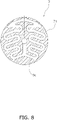
FIG. 7 orFIG. 8 , the firstcooling flow pathway 9a includes a plurality of paths in the interior of thesidewall portion 71. In the present preferred embodiment, the firstcooling flow pathway 9a is divided into two paths in the interior of thesidewall portion 71. In the interior of thesidewall portion 71, the firstcooling flow pathway 9a extends from the middle part to the outer peripheral part not in a straight shape but in a winding shape. - The first
cooling flow pathway 9a may include a plurality of paths in the interior of theouter wall portion 72 as well. In the present preferred embodiment, the firstcooling flow pathway 9a is divided into, for instance, three paths in the interior of theouter wall portion 72. The firstcooling flow pathway 9a axially extends in a straight shape in the interior of theouter wall portion 72. Alternatively, the firstcooling flow pathway 9a may extend in a winding shape in the interior of theouter wall portion 72. - As shown in
FIG. 6 , thehydraulic fluid sump 91 is disposed to axially interpose thetorque converter 3 together with thesidewall portion 71 therebetween. In other words, thehydraulic fluid sump 91, thetorque converter 3 and thesidewall portion 71 are axially aligned in this order. Thehydraulic fluid sump 91 is disposed in the interior of thereducer casing 42. Thehydraulic fluid sump 91 is disposed above the rotational axis O. - The
hydraulic fluid sump 91 contains the hydraulic fluid to be supplied to thetorque converter 3 in the interior thereof. Thehydraulic fluid sump 91 is provided with asupply port 92 in the bottom surface thereof. The hydraulic fluid, discharged from thesupply port 92, is supplied to thetorque converter 3 through aflow pathway 106 provided between thestationary shaft 104 and thesecond boss portion 323a of theimpeller hub 323. - Specifically, a centrifugal force is generated in rotation of the
impeller 32 of thetorque converter 3, whereby the hydraulic fluid residing in the interior of theflow pathway 106 is supplied to the interior of the torus T through thesupply flow pathways 324. Then, the hydraulic fluid, discharged from thetorque converter 3, flows to the firstcooling flow pathway 9a through the communicatingpathway 51. Subsequently, the hydraulic fluid, cooled while flowing through the firstcooling flow pathway 9a, is returned to thehydraulic fluid sump 91. - As shown in
FIG. 1 , thebrake sensor 81, theaccelerator sensor 82 and thevehicle velocity sensor 83 are connected to thecontroller 80 by wired or wireless means such that information is communicable therebetween. Thebrake sensor 81 is configured to detect a braking operation amount. For example, thebrake sensor 81 is configured to detect the amount of stroke of a brake pedal, a tread force or so forth. Thebrake sensor 81 outputs the detected braking operation amount to thecontroller 80. - The
accelerator sensor 82 is configured to detect an accelerator opening degree. Theaccelerator sensor 82 outputs the detected accelerator opening degree to thecontroller 80. - The
vehicle velocity sensor 83 is configured to detect the velocity of a vehicle in which thedrive unit 100 is installed. Thevehicle velocity sensor 83 outputs the detected vehicle velocity to thecontroller 80. - The
controller 80 is configured to control a torque outputted from themotor 2. For example, thecontroller 80 includes an ECU (Electronic Control Unit), a PCU (Power Control Unit) and so forth. Thecontroller 80 causes themotor 2 and thebattery 84 to transmit and receive electric power therebetween through an inverter circuit and a converter circuit, both of which are included in the PCU. Thecontroller 80 is capable of controlling the torque outputted from themotor 2 by controlling the electric power outputted from thebattery 84. - The
controller 80 executes first, second and third controls. For example, thecontroller 80 determines which of the first, second and third controls should be executed based on the accelerator opening degree and the vehicle velocity. More specifically, thecontroller 80 determines whether or not the accelerator opening degree is greater than 0%. When the accelerator opening degree is 0%, i.e., when the accelerator is not being operated, thecontroller 80 executes the first or third control. On the other hand, when the accelerator opening degree is greater than 0%, i.e., when the accelerator is being operated, thecontroller 80 executes the second control. - Furthermore, when the vehicle velocity is less than or equal to a first threshold, the
controller 80 executes the first control. The first threshold, albeit not limited to a specific value, is set to be, for instance, 10 km/h. Detailedly, when the accelerator opening degree is 0% and simultaneously the vehicle velocity is less than or equal to the first threshold, thecontroller 80 executes the first control. On the other hand, when the vehicle velocity is greater than the first threshold, thecontroller 80 executes the third control. Detailedly, when the accelerator opening degree is 0% and simultaneously the vehicle velocity is greater than the first threshold, thecontroller 80 executes the third control. - When executing the first control, the
controller 80 controls the torque outputted from themotor 2 based on the braking operation amount. Detailedly, thecontroller 80 obtains the braking operation amount from thebrake sensor 81. Then, thecontroller 80 determines whether or not the braking operation amount is greater than or equal to a second threshold. - When determining that the braking operation amount is greater than or equal to the second threshold, the
controller 80 makes zero the torque outputted from themotor 2. In other words, thecontroller 80 stops themotor 2. On the other hand, when determining that the braking operation amount is less than the second threshold, thecontroller 80 drives themotor 2. For example, thecontroller 80 drives themotor 2 such that the torque outputted from themotor 2 increases with reduction in braking operation amount. - On the other hand, when executing the second control, the
controller 80 stops the first control and controls the torque outputted from themotor 2 based on the accelerator opening degree. In other words, when executing the second control, thecontroller 80 controls the torque outputted from themotor 2 based on the accelerator opening degree regardless of the braking operation amount. - When executing the third control, the
controller 80 either controls the torque outputted from themotor 2 or executes regenerative control such that the vehicle velocity becomes less than or equal to the first threshold. For example, thecontroller 80 decelerates the vehicle such that the vehicle velocity becomes less than or equal to the first threshold by regulating the regenerative amount of themotor 2. - Next, a control method employed by the
controller 80 will be explained. - As shown in
FIG. 9 , thecontroller 80 determines whether or not an accelerator pedal is being operated (step S1). Specifically, thecontroller 80 determines whether or not the accelerator pedal is being operated based on the accelerator opening degree detected by theaccelerator sensor 82. When determining that the accelerator opening degree is greater than 0% (Yes in step S1), thecontroller 80 executes the second control (step S4). - On the other hand, when determining that the accelerator opening degree is 0% (No in step S1), the
controller 80 then determines whether or not the vehicle velocity is less than or equal to the first threshold (step S2). Specifically, thecontroller 80 determines whether or not the vehicle velocity detected by thevehicle velocity sensor 83 is less than or equal to the first threshold. When determining that the vehicle velocity is less than or equal to the first threshold (Yes in step S2), thecontroller 80 executes the first control (step S3). On the other hand, when determining that the vehicle velocity is greater than the first threshold (No in step S2), thecontroller 80 executes the third control (step S5). - Next, a control method employed by the
controller 80 in executing the first control will be explained. As shown inFIG. 10 , when executing the first control, thecontroller 80 determines whether or not the braking operation amount is greater than or equal to the second threshold (step S11). When determining that the braking operation amount is greater than or equal to the second threshold (Yes in step S11), thecontroller 80 makes zero the torque outputted from themotor 2. In other words, thecontroller 80 stops the motor 2 (step S12). - On the other hand, when determining that the braking operation amount is less than the second threshold (No in step S11), the
controller 80 drives the motor 2 (step S13). Specifically, thecontroller 80 increases the torque outputted from themotor 2 with reduction in braking operation amount. - According to the configuration described above, the following action is enabled when a vehicle starts moving on a slope. First in general, while the car is being stopped on the slope, the braking operation amount is greater than or equal to the second threshold. Because of this, the
controller 80 makes zero the torque outputted from themotor 2, whereby themotor 2 is being stopped. - Next, the brake pedal is gradually depressed when the vehicle starts moving, whereby the braking operation amount is gradually reduced. In accordance with this, the
controller 80 gradually increases the torque outputted from themotor 2. It should be noted that the brake pedal is not being completely released, and hence, the vehicle is kept stopped by a braking force applied by friction braking and so forth. - Next, when the brake pedal is released, the vehicle is enabled to smoothly start moving on the slope without moving backward, because the
motor 2 has been already driven. It should be noted that immediately before the vehicle starts moving, themotor 2 is being driven by thecontroller 80 while the vehicle is being stopped. Themotor 2, when driven, can be herein rotated even while the vehicle is being stopped, because thedrive unit 100 according to the present preferred embodiment includes thetorque converter 3. Because of this,motor 2 can be inhibited from generating heat. - As shown in
FIG. 11 , the torque converter unit may further include a secondcooling flow pathway 9b. The secondcooling flow pathway 9b extends through the interior of acompartment 107 of a vehicle into which the torque converter unit is installed. The hydraulic fluid, discharged from thetorque converter 3, flows through the secondcooling flow pathway 9b. The hydraulic fluid, flowing through the secondcooling flow pathway 9b, is cooled while dissipating heat thereof into thecompartment 107. - The hydraulic fluid is supplied to the second
cooling flow pathway 9b from the communicatingpathway 51. Additionally, the hydraulic fluid is returned to thehydraulic fluid sump 91 through the secondcooling flow pathway 9b. - The torque converter unit further includes a
selector mechanism 11. Theselector mechanism 11 is configured to select either the firstcooling flow pathway 9a or the secondcooling flow pathway 9b as a cooling flow pathway for supplying the hydraulic fluid discharged from thetorque converter 3. - As shown in
FIG. 12 , thetorque converter 3 may further include a plurality ofelastic members 38. Theelastic members 38 are disposed circumferentially between the first one-way clutch 35 and thecover 31. Theelastic members 38 transmit a torque applied in the reverse rotational direction from thecover 31 to the first one-way clutch 35. It should be noted that, when thecover 31 is rotated with respect to the first one-way clutch 35 by more than a predetermined angle in the reverse rotational direction, first stopper surfaces 314 of thecover 31 make contact with second stopper surfaces 351 of the first one-way clutch 35. As a result, the torque, applied from thecover 31, is directly transmitted to the first one-way clutch 35. - In reverse rotation as described above, the torque, applied from the
cover 31, is firstly transmitted to the first one-way clutch 35 through theelastic members 38, whereby massive and sudden torque transmission can be eased. - It should be noted that the
elastic members 38 may be disposed circumferentially between the first one-way clutch 35 and theturbine 33. In this case, theelastic members 38 transmit a torque, applied from the first one-way clutch 35 in the reverse rotational direction, to theturbine 33. - As shown in
FIG. 13 , the present power transmission mechanism may include aplanetary gear mechanism 400 and a clutch 401. Theplanetary gear mechanism 400 includes asun gear 402, a plurality of planet gears 403, aplanet carrier 404 and aring gear 405. - The
sun gear 402 is attached to theinput shaft 5. Thesun gear 402 is unitarily rotated with theinput shaft 5. Theplanet carrier 404 is attached to theoutput shaft 6. Theplanet carrier 404 is unitarily rotated with theoutput shaft 6. - The clutch 401 is disposed between a non-rotatable member (e.g., the
reducer casing 42 or the prime mover casing 21) and thering gear 405. Besides, the clutch 401 is configured to brake rotation of thering gear 405. - The clutch 401 is, for instance, a one-way clutch. The clutch 401 makes the
ring gear 405 rotatable in forward rotation of theinput shaft 5 and theoutput shaft 6. By contrast, the clutch 401 makes thering gear 405 non-rotatable in reverse rotation of theinput shaft 5 and theoutput shaft 6. - According to this configuration, when the
input shaft 5 and theoutput shaft 6 are forwardly rotated, in other words, when the vehicle is forwardly moved, thering gear 405 is being rotated without being fixed, whereby an amplifying action does not work in theplanetary gear mechanism 400. Because of this, the torque, outputted from themotor 2, is transmitted to thedrive wheels 101 through thetorque converter 3 and thereducer 4. - By contrast, when the
input shaft 5 and theoutput shaft 6 are reversely rotated, in other words, when the vehicle is backwardly moved, the clutch 401 makes thering gear 405 non-rotatable, whereby the amplifying function works in theplanetary gear mechanism 400. Because of this, the torque, outputted from themotor 2, is transmitted to thedrive wheels 101 through thereducer 4, while being amplified by theplanetary gear mechanism 400. -
- 11 Selector mechanism
- 2 Motor (electric)
- 21 Primary casing
- 22 Stator (of motor)
- 23 Rotor
- 3 Torque converter
- 31 Cover
- 311 Disc portion
- 312 Cylindrical portion
- 313 Cover hub
- 313a First boss portion
- 313b First flange portion
- 313c Protruding portion
- 313d Through hole
- 314 First stopper surface
- 32 Impeller
- 321 Impeller shell
- 322 Impeller blade
- 323 Impeller hub
- 323a Second boss portion
- 323b Second flange portion
- 324 Supply flow pathway
- 33 Turbine
- 331 Turbine shell
- 332 Turbine blade
- 333 Turbine hub
- 333a Third boss portion
- 333b Third flange portion
- 333c Cutout
- 34 Stator (of torque converter)
- 341 Stator carrier
- 342 Stator blade
- 35 First one-way clutch
- 351 First stopper surface
- 36 Second one-way clutch
- 37 Centrifugal clutch
- 371 Centrifugal element
- 372 Friction material
- 38 Elastic member
- 4 Reducer
- 41 Gear
- 42 Reducer casing
- 5 Input shaft
- 51 Communication pathway
- 6 Output shaft
- 7 Torque converter casing
- 71 Sidewall portion
- 72 Outer wall portion
- 73 Heat dissipation fin
- 9a first cooling
flow pathway 9b Second cooling flow pathway - 80 Controller
- 81 Brake sensor
- 82 Accelerator sensor
- 83 Vehicle velocity sensor
- 84 Battery
- 91 Hydraulic fluid sump
- 100 Drive unit
- 101 Drive wheel
- 102 Bearing member
- 103 Bearing member
- 104 Stationary shaft
- 105 Bearing member
- 106 Flow pathway
- 107 Compartment
- 109 Differential gear
- 400 Planetary gear mechanism
- 401 Clutch
- 402 Sun gear
- 403 Planet gear
- 404 Planet carrier
- 405 Ring gear
- O Rotational axis
- T Torus
Claims (7)
- A drive unit (100) for a vehicle comprising:an electric motor (2);a brake sensor (81) detecting a braking operation amount; anda controller (80);characterized in that the drive unit (100) further comprises a torque converter (3) to which a torque outputted from the motor (2) is inputted and in that the controller (80) is configured for executing a first control (S3) of controlling the torque outputted from the motor (2) based on the braking operation amount such that, even during stop of the vehicle, the motor (2) can be kept rotated.
- The drive unit (100) according to claim 1, further comprising:an accelerator sensor (82) detecting an accelerator opening degree, whereinthe controller (80) executes the first control (S3) when the accelerator opening degree is 0%.
- The drive unit (100) according to claim 2, wherein the controller (80) executes a second control when the accelerator opening degree is greater than 0%, the second control executed to stop the first control and control the torque outputted from the motor (2) based on the accelerator opening degree.
- The drive unit (100) according to claim 2 or 3, further comprising:a vehicle velocity sensor (83) detecting a vehicle velocity, whereinthe controller (80) executes a third control when the accelerator opening degree is 0% and simultaneously the vehicle velocity is greater than a first threshold, the third control executed to either control the torque outputted from the motor (2) or execute a regenerative control such that the vehicle velocity becomes less than or equal to the first threshold.
- The drive unit (100) according to any of claims 1 to 3, further comprising:a vehicle velocity sensor (83) detecting a vehicle velocity, whereinthe controller (80) executes the first control (S3) when the vehicle velocity is less than or equal to a first threshold.
- The drive unit (100) according to any of claims 1 to 5, wherein the controller (80) controls the torque outputted from the motor (2) such that the torque increases with reduction in the braking operation amount in executing the first control.
- The drive unit (100) according to any of claims 1 to 6, wherein the controller (80) makes zero the torque outputted from the motor (2) when the braking operation amount is greater than or equal to a second threshold in executing the first control.
Applications Claiming Priority (1)
| Application Number | Priority Date | Filing Date | Title |
|---|---|---|---|
| JP2019091193A JP7345273B2 (en) | 2019-05-14 | 2019-05-14 | drive unit |
Publications (2)
| Publication Number | Publication Date |
|---|---|
| EP3738844A1 EP3738844A1 (en) | 2020-11-18 |
| EP3738844B1 true EP3738844B1 (en) | 2023-01-18 |
Family
ID=70740426
Family Applications (1)
| Application Number | Title | Priority Date | Filing Date |
|---|---|---|---|
| EP20173418.3A Active EP3738844B1 (en) | 2019-05-14 | 2020-05-07 | Drive unit |
Country Status (4)
| Country | Link |
|---|---|
| US (1) | US20200361321A1 (en) |
| EP (1) | EP3738844B1 (en) |
| JP (1) | JP7345273B2 (en) |
| CN (1) | CN111942171B (en) |
Family Cites Families (20)
| Publication number | Priority date | Publication date | Assignee | Title |
|---|---|---|---|---|
| JPH05330348A (en) * | 1992-04-01 | 1993-12-14 | Aqueous Res:Kk | Hydraulic control device in hybrid vehicle |
| JP3396868B2 (en) * | 1995-05-25 | 2003-04-14 | 株式会社エクォス・リサーチ | Hybrid vehicle |
| JPH0937415A (en) * | 1995-07-20 | 1997-02-07 | Suzuki Motor Corp | Drive controller for electric vehicle |
| JP3646642B2 (en) * | 1999-10-08 | 2005-05-11 | トヨタ自動車株式会社 | Vehicle drive control device |
| US6307277B1 (en) * | 2000-04-18 | 2001-10-23 | General Motors Corporation | Apparatus and method for a torque and fuel control system for a hybrid vehicle |
| DE10065589A1 (en) * | 2000-12-28 | 2002-07-04 | Bosch Gmbh Robert | Drive control for motor vehicle has hill brake with pedal position sensor circuit to detect end of pedal use and operate drive |
| DE10104498B4 (en) * | 2001-01-31 | 2014-09-11 | Continental Teves Ag & Co. Ohg | Method for activating a traction help function |
| JP3922157B2 (en) * | 2002-10-18 | 2007-05-30 | トヨタ自動車株式会社 | Vehicle drive control device |
| JP3909696B2 (en) * | 2002-12-27 | 2007-04-25 | アイシン・エィ・ダブリュ株式会社 | Control device for hybrid vehicle |
| JP2005016618A (en) * | 2003-06-25 | 2005-01-20 | Mitsubishi Motors Corp | Automatic transmission device of a/t vehicle |
| FR2863992B1 (en) * | 2003-12-23 | 2007-03-23 | Giat Ind Sa | BRAKE CONTROL OF AN ELECTRIC VEHICLE WITH ENERGY RECOVERY |
| JP4500277B2 (en) * | 2006-02-28 | 2010-07-14 | モトール自動車株式会社 | Power transmission device |
| JP2010179882A (en) * | 2009-02-09 | 2010-08-19 | Nissan Motor Co Ltd | Restart control device and method for vehicle |
| TWI394346B (en) | 2010-05-14 | 2013-04-21 | Giga Byte Tech Co Ltd | Mother board with rapid charging handheld multimedia device |
| CN103946092B (en) * | 2011-12-09 | 2016-08-31 | 丰田自动车株式会社 | The control device of motor vehicle driven by mixed power |
| DE102013000838A1 (en) * | 2013-01-21 | 2014-07-24 | Getrag Getriebe- Und Zahnradfabrik Hermann Hagenmeyer Gmbh & Cie Kg | Method for holding a motor vehicle on a slope |
| JP6098480B2 (en) * | 2013-11-11 | 2017-03-22 | トヨタ自動車株式会社 | Vehicle control device |
| JP2017020574A (en) * | 2015-07-10 | 2017-01-26 | トヨタ自動車株式会社 | Control device of electric vehicle |
| JP6699204B2 (en) * | 2016-02-01 | 2020-05-27 | いすゞ自動車株式会社 | Electric car |
| JP2017184338A (en) * | 2016-03-28 | 2017-10-05 | パナソニックIpマネジメント株式会社 | Vehicle control device, vehicle control method, and vehicle control program |
-
2019
- 2019-05-14 JP JP2019091193A patent/JP7345273B2/en active Active
-
2020
- 2020-03-30 US US16/834,530 patent/US20200361321A1/en not_active Abandoned
- 2020-05-07 EP EP20173418.3A patent/EP3738844B1/en active Active
- 2020-05-07 CN CN202010377310.0A patent/CN111942171B/en active Active
Also Published As
| Publication number | Publication date |
|---|---|
| EP3738844A1 (en) | 2020-11-18 |
| CN111942171B (en) | 2024-02-06 |
| US20200361321A1 (en) | 2020-11-19 |
| JP2020188567A (en) | 2020-11-19 |
| CN111942171A (en) | 2020-11-17 |
| JP7345273B2 (en) | 2023-09-15 |
Similar Documents
| Publication | Publication Date | Title |
|---|---|---|
| US8540602B2 (en) | Drive device for hybrid vehicle | |
| EP3730815B1 (en) | Torque converter comprising first and second one-way clutch | |
| JPH0211419A (en) | Motor driving device with reduction gear and motor driven vehicle | |
| US11434979B2 (en) | Drive unit | |
| CN115052774A (en) | Compact P2 hybrid architecture | |
| US20110240428A1 (en) | Control device for vehicular power transmitting system and corresponding method | |
| JP5158418B2 (en) | Vehicle drive device | |
| EP3738844B1 (en) | Drive unit | |
| US20220399779A1 (en) | Drive unit | |
| US20220314768A1 (en) | Drive unit | |
| JP7272863B2 (en) | drive unit | |
| US11035450B2 (en) | Drive unit | |
| JP7349922B2 (en) | drive unit | |
| JP2020172977A (en) | Torque converter unit | |
| JP2009236233A (en) | Power transmission device | |
| CN112238749B (en) | Driving unit | |
| JPH08216864A (en) | Hydrodynamic retarder unit | |
| JP2010013073A (en) | Hybrid vehicle drive mechanism | |
| JP2001130273A (en) | Power transmission for vehicle, and its operating method | |
| JP2020172976A (en) | Torque converter | |
| JP4690360B2 (en) | Coupling | |
| JP2009120117A (en) | Drive unit for vehicle | |
| JPH0637647U (en) | Automatic transmission with torque converter | |
| JPH0576930U (en) | Fluid retarder |
Legal Events
| Date | Code | Title | Description |
|---|---|---|---|
| PUAI | Public reference made under article 153(3) epc to a published international application that has entered the european phase |
Free format text: ORIGINAL CODE: 0009012 |
|
| STAA | Information on the status of an ep patent application or granted ep patent |
Free format text: STATUS: THE APPLICATION HAS BEEN PUBLISHED |
|
| AK | Designated contracting states |
Kind code of ref document: A1 Designated state(s): AL AT BE BG CH CY CZ DE DK EE ES FI FR GB GR HR HU IE IS IT LI LT LU LV MC MK MT NL NO PL PT RO RS SE SI SK SM TR |
|
| AX | Request for extension of the european patent |
Extension state: BA ME |
|
| STAA | Information on the status of an ep patent application or granted ep patent |
Free format text: STATUS: REQUEST FOR EXAMINATION WAS MADE |
|
| 17P | Request for examination filed |
Effective date: 20210413 |
|
| RBV | Designated contracting states (corrected) |
Designated state(s): AL AT BE BG CH CY CZ DE DK EE ES FI FR GB GR HR HU IE IS IT LI LT LU LV MC MK MT NL NO PL PT RO RS SE SI SK SM TR |
|
| GRAP | Despatch of communication of intention to grant a patent |
Free format text: ORIGINAL CODE: EPIDOSNIGR1 |
|
| STAA | Information on the status of an ep patent application or granted ep patent |
Free format text: STATUS: GRANT OF PATENT IS INTENDED |
|
| INTG | Intention to grant announced |
Effective date: 20220928 |
|
| GRAS | Grant fee paid |
Free format text: ORIGINAL CODE: EPIDOSNIGR3 |
|
| GRAA | (expected) grant |
Free format text: ORIGINAL CODE: 0009210 |
|
| STAA | Information on the status of an ep patent application or granted ep patent |
Free format text: STATUS: THE PATENT HAS BEEN GRANTED |
|
| AK | Designated contracting states |
Kind code of ref document: B1 Designated state(s): AL AT BE BG CH CY CZ DE DK EE ES FI FR GB GR HR HU IE IS IT LI LT LU LV MC MK MT NL NO PL PT RO RS SE SI SK SM TR |
|
| REG | Reference to a national code |
Ref country code: GB Ref legal event code: FG4D |
|
| REG | Reference to a national code |
Ref country code: CH Ref legal event code: EP |
|
| REG | Reference to a national code |
Ref country code: DE Ref legal event code: R096 Ref document number: 602020007617 Country of ref document: DE |
|
| REG | Reference to a national code |
Ref country code: AT Ref legal event code: REF Ref document number: 1544513 Country of ref document: AT Kind code of ref document: T Effective date: 20230215 Ref country code: IE Ref legal event code: FG4D |
|
| REG | Reference to a national code |
Ref country code: LT Ref legal event code: MG9D |
|
| REG | Reference to a national code |
Ref country code: NL Ref legal event code: MP Effective date: 20230118 |
|
| REG | Reference to a national code |
Ref country code: AT Ref legal event code: MK05 Ref document number: 1544513 Country of ref document: AT Kind code of ref document: T Effective date: 20230118 |
|
| PG25 | Lapsed in a contracting state [announced via postgrant information from national office to epo] |
Ref country code: NL Free format text: LAPSE BECAUSE OF FAILURE TO SUBMIT A TRANSLATION OF THE DESCRIPTION OR TO PAY THE FEE WITHIN THE PRESCRIBED TIME-LIMIT Effective date: 20230118 |
|
| PG25 | Lapsed in a contracting state [announced via postgrant information from national office to epo] |
Ref country code: RS Free format text: LAPSE BECAUSE OF FAILURE TO SUBMIT A TRANSLATION OF THE DESCRIPTION OR TO PAY THE FEE WITHIN THE PRESCRIBED TIME-LIMIT Effective date: 20230118 Ref country code: PT Free format text: LAPSE BECAUSE OF FAILURE TO SUBMIT A TRANSLATION OF THE DESCRIPTION OR TO PAY THE FEE WITHIN THE PRESCRIBED TIME-LIMIT Effective date: 20230518 Ref country code: NO Free format text: LAPSE BECAUSE OF FAILURE TO SUBMIT A TRANSLATION OF THE DESCRIPTION OR TO PAY THE FEE WITHIN THE PRESCRIBED TIME-LIMIT Effective date: 20230418 Ref country code: LV Free format text: LAPSE BECAUSE OF FAILURE TO SUBMIT A TRANSLATION OF THE DESCRIPTION OR TO PAY THE FEE WITHIN THE PRESCRIBED TIME-LIMIT Effective date: 20230118 Ref country code: LT Free format text: LAPSE BECAUSE OF FAILURE TO SUBMIT A TRANSLATION OF THE DESCRIPTION OR TO PAY THE FEE WITHIN THE PRESCRIBED TIME-LIMIT Effective date: 20230118 Ref country code: HR Free format text: LAPSE BECAUSE OF FAILURE TO SUBMIT A TRANSLATION OF THE DESCRIPTION OR TO PAY THE FEE WITHIN THE PRESCRIBED TIME-LIMIT Effective date: 20230118 Ref country code: ES Free format text: LAPSE BECAUSE OF FAILURE TO SUBMIT A TRANSLATION OF THE DESCRIPTION OR TO PAY THE FEE WITHIN THE PRESCRIBED TIME-LIMIT Effective date: 20230118 Ref country code: AT Free format text: LAPSE BECAUSE OF FAILURE TO SUBMIT A TRANSLATION OF THE DESCRIPTION OR TO PAY THE FEE WITHIN THE PRESCRIBED TIME-LIMIT Effective date: 20230118 |
|
| PGFP | Annual fee paid to national office [announced via postgrant information from national office to epo] |
Ref country code: DE Payment date: 20230331 Year of fee payment: 4 |
|
| PG25 | Lapsed in a contracting state [announced via postgrant information from national office to epo] |
Ref country code: SE Free format text: LAPSE BECAUSE OF FAILURE TO SUBMIT A TRANSLATION OF THE DESCRIPTION OR TO PAY THE FEE WITHIN THE PRESCRIBED TIME-LIMIT Effective date: 20230118 Ref country code: PL Free format text: LAPSE BECAUSE OF FAILURE TO SUBMIT A TRANSLATION OF THE DESCRIPTION OR TO PAY THE FEE WITHIN THE PRESCRIBED TIME-LIMIT Effective date: 20230118 Ref country code: IS Free format text: LAPSE BECAUSE OF FAILURE TO SUBMIT A TRANSLATION OF THE DESCRIPTION OR TO PAY THE FEE WITHIN THE PRESCRIBED TIME-LIMIT Effective date: 20230518 Ref country code: GR Free format text: LAPSE BECAUSE OF FAILURE TO SUBMIT A TRANSLATION OF THE DESCRIPTION OR TO PAY THE FEE WITHIN THE PRESCRIBED TIME-LIMIT Effective date: 20230419 Ref country code: FI Free format text: LAPSE BECAUSE OF FAILURE TO SUBMIT A TRANSLATION OF THE DESCRIPTION OR TO PAY THE FEE WITHIN THE PRESCRIBED TIME-LIMIT Effective date: 20230118 |
|
| REG | Reference to a national code |
Ref country code: DE Ref legal event code: R097 Ref document number: 602020007617 Country of ref document: DE |
|
| PG25 | Lapsed in a contracting state [announced via postgrant information from national office to epo] |
Ref country code: SM Free format text: LAPSE BECAUSE OF FAILURE TO SUBMIT A TRANSLATION OF THE DESCRIPTION OR TO PAY THE FEE WITHIN THE PRESCRIBED TIME-LIMIT Effective date: 20230118 Ref country code: RO Free format text: LAPSE BECAUSE OF FAILURE TO SUBMIT A TRANSLATION OF THE DESCRIPTION OR TO PAY THE FEE WITHIN THE PRESCRIBED TIME-LIMIT Effective date: 20230118 Ref country code: EE Free format text: LAPSE BECAUSE OF FAILURE TO SUBMIT A TRANSLATION OF THE DESCRIPTION OR TO PAY THE FEE WITHIN THE PRESCRIBED TIME-LIMIT Effective date: 20230118 Ref country code: DK Free format text: LAPSE BECAUSE OF FAILURE TO SUBMIT A TRANSLATION OF THE DESCRIPTION OR TO PAY THE FEE WITHIN THE PRESCRIBED TIME-LIMIT Effective date: 20230118 Ref country code: CZ Free format text: LAPSE BECAUSE OF FAILURE TO SUBMIT A TRANSLATION OF THE DESCRIPTION OR TO PAY THE FEE WITHIN THE PRESCRIBED TIME-LIMIT Effective date: 20230118 |
|
| PLBE | No opposition filed within time limit |
Free format text: ORIGINAL CODE: 0009261 |
|
| STAA | Information on the status of an ep patent application or granted ep patent |
Free format text: STATUS: NO OPPOSITION FILED WITHIN TIME LIMIT |
|
| PG25 | Lapsed in a contracting state [announced via postgrant information from national office to epo] |
Ref country code: SK Free format text: LAPSE BECAUSE OF FAILURE TO SUBMIT A TRANSLATION OF THE DESCRIPTION OR TO PAY THE FEE WITHIN THE PRESCRIBED TIME-LIMIT Effective date: 20230118 |
|
| 26N | No opposition filed |
Effective date: 20231019 |
|
| REG | Reference to a national code |
Ref country code: CH Ref legal event code: PL |
|
| PG25 | Lapsed in a contracting state [announced via postgrant information from national office to epo] |
Ref country code: MC Free format text: LAPSE BECAUSE OF FAILURE TO SUBMIT A TRANSLATION OF THE DESCRIPTION OR TO PAY THE FEE WITHIN THE PRESCRIBED TIME-LIMIT Effective date: 20230118 |
|
| REG | Reference to a national code |
Ref country code: BE Ref legal event code: MM Effective date: 20230531 |
|
| PG25 | Lapsed in a contracting state [announced via postgrant information from national office to epo] |
Ref country code: SI Free format text: LAPSE BECAUSE OF FAILURE TO SUBMIT A TRANSLATION OF THE DESCRIPTION OR TO PAY THE FEE WITHIN THE PRESCRIBED TIME-LIMIT Effective date: 20230118 Ref country code: MC Free format text: LAPSE BECAUSE OF FAILURE TO SUBMIT A TRANSLATION OF THE DESCRIPTION OR TO PAY THE FEE WITHIN THE PRESCRIBED TIME-LIMIT Effective date: 20230118 Ref country code: LU Free format text: LAPSE BECAUSE OF NON-PAYMENT OF DUE FEES Effective date: 20230507 Ref country code: LI Free format text: LAPSE BECAUSE OF NON-PAYMENT OF DUE FEES Effective date: 20230531 Ref country code: CH Free format text: LAPSE BECAUSE OF NON-PAYMENT OF DUE FEES Effective date: 20230531 |
|
| REG | Reference to a national code |
Ref country code: IE Ref legal event code: MM4A |
|
| PG25 | Lapsed in a contracting state [announced via postgrant information from national office to epo] |
Ref country code: IE Free format text: LAPSE BECAUSE OF NON-PAYMENT OF DUE FEES Effective date: 20230507 |
|
| PG25 | Lapsed in a contracting state [announced via postgrant information from national office to epo] |
Ref country code: IE Free format text: LAPSE BECAUSE OF NON-PAYMENT OF DUE FEES Effective date: 20230507 |