EP3738837B1 - Bordnetz und kraftfahrzeug mit bordnetz - Google Patents
Bordnetz und kraftfahrzeug mit bordnetz Download PDFInfo
- Publication number
- EP3738837B1 EP3738837B1 EP20172185.9A EP20172185A EP3738837B1 EP 3738837 B1 EP3738837 B1 EP 3738837B1 EP 20172185 A EP20172185 A EP 20172185A EP 3738837 B1 EP3738837 B1 EP 3738837B1
- Authority
- EP
- European Patent Office
- Prior art keywords
- module
- bus
- control
- electrical system
- user data
- Prior art date
- Legal status (The legal status is an assumption and is not a legal conclusion. Google has not performed a legal analysis and makes no representation as to the accuracy of the status listed.)
- Active
Links
Images
Classifications
-
- B—PERFORMING OPERATIONS; TRANSPORTING
- B60—VEHICLES IN GENERAL
- B60R—VEHICLES, VEHICLE FITTINGS, OR VEHICLE PARTS, NOT OTHERWISE PROVIDED FOR
- B60R16/00—Electric or fluid circuits specially adapted for vehicles and not otherwise provided for; Arrangement of elements of electric or fluid circuits specially adapted for vehicles and not otherwise provided for
- B60R16/02—Electric or fluid circuits specially adapted for vehicles and not otherwise provided for; Arrangement of elements of electric or fluid circuits specially adapted for vehicles and not otherwise provided for electric constitutive elements
- B60R16/023—Electric or fluid circuits specially adapted for vehicles and not otherwise provided for; Arrangement of elements of electric or fluid circuits specially adapted for vehicles and not otherwise provided for electric constitutive elements for transmission of signals between vehicle parts or subsystems
-
- B—PERFORMING OPERATIONS; TRANSPORTING
- B60—VEHICLES IN GENERAL
- B60R—VEHICLES, VEHICLE FITTINGS, OR VEHICLE PARTS, NOT OTHERWISE PROVIDED FOR
- B60R21/00—Arrangements or fittings on vehicles for protecting or preventing injuries to occupants or pedestrians in case of accidents or other traffic risks
- B60R21/01—Electrical circuits for triggering passive safety arrangements, e.g. airbags, safety belt tighteners, in case of vehicle accidents or impending vehicle accidents
- B60R21/015—Electrical circuits for triggering passive safety arrangements, e.g. airbags, safety belt tighteners, in case of vehicle accidents or impending vehicle accidents including means for detecting the presence or position of passengers, passenger seats or child seats, and the related safety parameters therefor, e.g. speed or timing of airbag inflation in relation to occupant position or seat belt use
-
- B—PERFORMING OPERATIONS; TRANSPORTING
- B60—VEHICLES IN GENERAL
- B60R—VEHICLES, VEHICLE FITTINGS, OR VEHICLE PARTS, NOT OTHERWISE PROVIDED FOR
- B60R21/00—Arrangements or fittings on vehicles for protecting or preventing injuries to occupants or pedestrians in case of accidents or other traffic risks
- B60R21/01—Electrical circuits for triggering passive safety arrangements, e.g. airbags, safety belt tighteners, in case of vehicle accidents or impending vehicle accidents
- B60R21/017—Electrical circuits for triggering passive safety arrangements, e.g. airbags, safety belt tighteners, in case of vehicle accidents or impending vehicle accidents including arrangements for providing electric power to safety arrangements or their actuating means, e.g. to pyrotechnic fuses or electro-mechanic valves
-
- B—PERFORMING OPERATIONS; TRANSPORTING
- B60—VEHICLES IN GENERAL
- B60R—VEHICLES, VEHICLE FITTINGS, OR VEHICLE PARTS, NOT OTHERWISE PROVIDED FOR
- B60R21/00—Arrangements or fittings on vehicles for protecting or preventing injuries to occupants or pedestrians in case of accidents or other traffic risks
- B60R21/01—Electrical circuits for triggering passive safety arrangements, e.g. airbags, safety belt tighteners, in case of vehicle accidents or impending vehicle accidents
- B60R2021/0104—Communication circuits for data transmission
- B60R2021/01047—Architecture
- B60R2021/01054—Bus
- B60R2021/01061—Bus between the airbag system and other vehicle electronic systems
-
- B—PERFORMING OPERATIONS; TRANSPORTING
- B60—VEHICLES IN GENERAL
- B60R—VEHICLES, VEHICLE FITTINGS, OR VEHICLE PARTS, NOT OTHERWISE PROVIDED FOR
- B60R21/00—Arrangements or fittings on vehicles for protecting or preventing injuries to occupants or pedestrians in case of accidents or other traffic risks
- B60R21/01—Electrical circuits for triggering passive safety arrangements, e.g. airbags, safety belt tighteners, in case of vehicle accidents or impending vehicle accidents
- B60R2021/0104—Communication circuits for data transmission
- B60R2021/01047—Architecture
- B60R2021/01054—Bus
- B60R2021/01068—Bus between different sensors and airbag control unit
-
- B—PERFORMING OPERATIONS; TRANSPORTING
- B60—VEHICLES IN GENERAL
- B60R—VEHICLES, VEHICLE FITTINGS, OR VEHICLE PARTS, NOT OTHERWISE PROVIDED FOR
- B60R21/00—Arrangements or fittings on vehicles for protecting or preventing injuries to occupants or pedestrians in case of accidents or other traffic risks
- B60R21/01—Electrical circuits for triggering passive safety arrangements, e.g. airbags, safety belt tighteners, in case of vehicle accidents or impending vehicle accidents
- B60R2021/0104—Communication circuits for data transmission
- B60R2021/01102—Transmission method
- B60R2021/01109—Transmission method power and data signal using transmission medium
Definitions
- the invention relates to an on-board network designed for a motor vehicle and having a branched structure with a first part and a second part.
- the invention also relates to a motor vehicle with such an on-board network.
- assemblies or modules are often prefabricated. These assemblies or modules are then installed as part of a final assembly, for example, in a type of basic assembly of the motor vehicle.
- such assemblies or modules also have electrical units that are part of the vehicle's electrical system when the vehicle is finished, or are at least connected to the vehicle's electrical system, and that are connected to the rest of the electrical system, in particular the rest of the electrical system in the basic assembly, when the corresponding assembly or module is installed.
- the connection is typically made using a large number of lines or cable connections.
- a corresponding seat with airbag is, for example, in the EP 3 135 531 A1 described.
- the invention is based on the object of specifying an advantageously designed on-board network and an advantageously designed motor vehicle.
- An on-board network according to the invention is designed for a motor vehicle and is set up to carry out or implement the processes, working methods and/or method steps described below in at least one operating mode. It has a branched structure, for example a tree structure, with a first part, with a second part and with a field bus.
- the field bus is designed to transmit user data, for example sensor data and/or control signals, between the first part and the second part and is designed, for example, in the manner of a LIN bus, a CAN bus, a CAN-FD bus or an Ethernet bus.
- a bus node is arranged in the second part and a control and evaluation unit connected to the bus node via the field bus is arranged in the first part.
- the second part can therefore also be referred to as a node area or node area.
- the field bus which is typically formed by a cable or a cable harness, only connects the control and evaluation unit to the bus node, so that the control and evaluation unit on the one hand and the bus node on the other hand form the two ends of a simple, unbranched field bus connection.
- the motor vehicle has a module with several auxiliary units designed as sensors and/or actuators.
- the auxiliary units are therefore part of the module and typically also part of the second part of the vehicle electrical system.
- the Bus node is part of the second part and usually also part of the module.
- the entire second part of the on-board network is part of the module.
- the bus node at least with regard to handling or processing user data, is preferably designed only for forwarding user data between the control and evaluation unit and the auxiliary units.
- the bus node is typically only designed to transmit user data from the auxiliary units to the control and evaluation unit or to transmit auxiliary data from the control and evaluation unit to the auxiliary units and in particular not to evaluate corresponding user data and in particular sensor data.
- the bus node is therefore preferably also not designed to evaluate user data and in particular sensor data in such a way that a control signal is generated in the bus node based on or due to user data or sensor data.
- the bus node thus represents a type of simple input-output node (I/O node) and functions, for example, (only) as a type of translator or converter that converts the user data or the signals containing the user data, for example, from a first format into a second format, one of these formats enabling the transmission of the user data via the fieldbus.
- I/O node simple input-output node
- functions for example, (only) as a type of translator or converter that converts the user data or the signals containing the user data, for example, from a first format into a second format, one of these formats enabling the transmission of the user data via the fieldbus.
- bus node if such a translation or conversion is carried out by the bus node, it is advantageous if data buffering is enabled in the bus node, for example by means of a typical buffer memory. Intermediate storage of the user data beyond such buffering for communication is, however, preferably not provided or enabled in the bus node.
- communication i.e. a transmission of user data via the fieldbus, is preferably initiated by the control and evaluation unit and in particular not by the bus node.
- the bus node serves (only) to transfer user data transmitted by the control and evaluation unit via the fieldbus. to assign it to an addressee and to forward it specifically to that addressee, in particular only to that addressee, i.e. to the auxiliary unit for which the user data is intended.
- a simple forwarding of user data via the bus node without translation or conversion of the user data is useful, for example, if the auxiliary units themselves generate or process user data in bus format, i.e. in a format suitable for transmission via the field bus.
- sensors for example, convert physical measured values themselves into user data in bus format.
- the bus node is also used to transmit or distribute electrical power, in particular to supply the auxiliary units.
- the field bus is then advantageously designed for power transmission, and thus in particular for "power line communication".
- the field bus is then designed as a PSI5 bus or a DSI3 bus, for example.
- electrical power is transmitted in parallel via a supply line, in particular parallel to the field bus and, for example, also past the bus node.
- the bus node is also preferably capable of partial network operation and, further preferably, the entire second part of the on-board network or the entire on-board network is capable of partial network operation, i.e. designed for partial network operation (e.g. CAN Partial Network).
- partial network operation e.g. CAN Partial Network
- the second part of the on-board network can be temporarily put into an inactive (sleeping) mode (see, for example, ISO 11898-5 or ISO 11898-6). In this way, energy consumption in the motor vehicle can be kept low or reduced.
- control and evaluation unit is preferably designed to evaluate user data and in particular sensor data and is typically more complex than the bus node. In many cases, it has a processor or a high-performance computing unit (HPC).
- the control and evaluation unit is also preferably designed to evaluate user data and in particular sensor data in such a way that at least in one operating mode in the control and evaluation unit generates a control signal or control data based on or due to user data or sensor data.
- the auxiliary units are typically sensors or actuators and accordingly the module then has one or more sensors and/or one or more actuators.
- a corresponding sensor is, for example, a temperature sensor, a humidity sensor, a pressure sensor, a sensor for detecting seat occupancy, a sensor for position detection or a sensor for detecting a person's vital signs, for example for detecting a heartbeat.
- a control element also forms a sensor within the meaning of this application, for example a button or a switch.
- an actuator is designed, for example, as a servomotor, for example for seat adjustment, as a heating element or as a lighting element, for example for a so-called "ambient light system”.
- the aforementioned user data is in most cases sensor data and/or control data, which is typically in the form of signals or is contained in signals.
- Auxiliary units designed as sensors typically generate sensor data as user data during operation and actuators are controlled when required using user data designed as control data.
- the on-board network is then expediently designed in such a way that the sensors generate sensor data as user data at least temporarily during operation and that this user data is then transmitted to the control and evaluation unit, in which the user data is usually processed and in particular evaluated.
- the user data is transmitted via the bus node and the field bus, with the user data generated by the sensors first being transmitted to the bus node.
- the user data generated by the sensors is typically not evaluated in the bus node, but in some cases it is prepared so that it can be transmitted via the field bus and thus forwarded to the control and evaluation unit.
- the user data generated by the sensors is typically in the form of sensor signals, which in some cases cannot be transmitted via the existing fieldbus in the form generated by the sensors. In these cases, the user data is converted or translated into a suitable format in the bus node. The exact way in which the bus node works depends on the design of the fieldbus.
- a simple example of an implementation would be the concept of frequency modulation.
- the sensor signals and thus the user data from different sensors are transmitted via a common field bus using a common signal by integrating the user data from the different sensors into different frequency bands, i.e. by using different frequency bands for the different user data and their transmission via the field bus.
- the bus node is then used in particular to modulate the different sensor signals onto a carrier signal, in particular in such a way that their information content is contained in different, separate frequency bands.
- auxiliary units designed as actuators it is then preferably the case that one or more control signals are to be generated to control one or more actuators and are generated when required.
- the generation or initiation of the generation typically takes place in the control and evaluation unit.
- Such a control signal is also user data within the meaning of this application or user data is contained in such a control signal.
- This user data is then to be transmitted by the control and evaluation unit to the corresponding actuator or actuators when required.
- Such user data is expediently generated by the control and evaluation unit in a format that allows transmission via the field bus. However, such a format is in some cases unsuitable for an actuator intended as a receiver or several actuators intended as receivers and in these cases a Format conversion to a format suitable for actuators.
- the bus node is used to assign and forward the user data transmitted by the control and evaluation unit via the field bus to the intended recipient, i.e. the intended actuator.
- the bus node distributes the user data and thus assigns and forwards it to the intended recipients.
- an airbag is arranged in the module described above. This airbag can only be controlled via the field bus and the bus node.
- no additional or separate electrical lines are provided for controlling the airbag, which are routed parallel to the field bus and which, for example, connect an airbag control unit to the airbag.
- a corresponding airbag control unit is connected to the airbag via the field bus and accordingly, if required or if triggered, a control signal is transmitted from the airbag control unit to the airbag via the field bus.
- the control and evaluation unit is connected in terms of signal technology to an airbag control unit, which is usually part of the first part and thus in particular not part of the module.
- the on-board network is then typically designed in such a way that the airbag control unit generates a control signal to control the airbag in the module when required and transmits this control signal as user data to the control and evaluation unit.
- this user data is then either simply forwarded to the airbag via the field bus and the bus node, or the corresponding user data is prepared for transmission via the field bus and, for example, converted into a different format. After transmission via the field bus, the user data is then converted back into a different format in the bus node, for example, and forwarded to the airbag and/or it is simply assigned to the airbag and then transmitted exclusively to the airbag.
- an airbag control unit as described above is not connected to the control and evaluation unit, but is integrated into the control and evaluation unit, so that the control and evaluation unit itself has or forms an airbag control unit.
- the control and evaluation unit in this case is designed to perform the functions of an airbag control unit, in particular an airbag control unit according to the state of the art, so that no additional device in the sense of a separate apparatus is required.
- the module is only connected to the first part and thus to the rest of the on-board network via the field bus and a single supply line.
- the supply line is used to transmit electrical power and preferably has exactly one phase or wire or exactly two phases or wires, for example for the positive and negative poles of a direct voltage source. It is typically not used to transmit information or user data and accordingly the supply line is not usually used for the corresponding transmission of user data.
- the module is only connected to the first part and thus also to the rest of the on-board network via the fieldbus. In such a case Then, preferably in at least one operating mode, electrical power is transferred from the first part to the second part and thus to the module via the fieldbus. Whether or not an additional supply line is used usually depends on the design of the fieldbus and thus the electrical power that can be transferred via the fieldbus as well as the expected electrical power requirement of the auxiliary units.
- a further advantageous design variant is one in which the entire module is free of evaluation units. This means that in this case not only is the bus node unable to evaluate information, in particular sensor data, but there is also no other unit in the module that has such a function or a corresponding capability. A corresponding evaluation function is then only possible in the first part and accordingly information and in particular sensor data can only be evaluated in the first part, for example by the control and evaluation unit.
- the module is then designed in such a way that no component or part of the module has a higher risk rating than ASIL B according to ISO 26262.
- the risk rating of the bus node is also typically less than or equal to ASIL B.
- All components or parts that have a higher risk rating, such as the control and evaluation unit (usually ASIL D) or the airbag control unit (usually ASIL D), and that are intended for the motor vehicle, are arranged in the first part of the on-board network and thus in the rest of the motor vehicle, i.e. not in the module.
- the motor vehicle has several modules of the type described above, with each further module having a further part of the on-board network with a further bus node that is connected to the first part via an associated further field bus.
- the bus nodes are preferably designed to be essentially identical and, more preferably, the field buses are also designed to be essentially identical.
- control and evaluation unit forms a kind of central control and evaluation unit in the motor vehicle.
- control and evaluation unit forms a kind of central control and evaluation unit in the motor vehicle.
- a centralized on-board network can also be implemented, which in extreme cases has the control and evaluation unit as the only control and evaluation unit. This then processes the user data from all sensors in the motor vehicle and controls all actuators and/or all airbags in the motor vehicle.
- a previously described module is designed, for example, as a seat, a door, a tailgate, a center console or a roof liner.
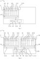
- a motor vehicle 2 described below as an example is in Fig. 1 shown schematically and has a module 4 designed as a seat.
- This module 4 or the seat is prefabricated during the manufacture of the motor vehicle 2, for example by a supplier, and installed during final assembly, i.e. in particular installed in a body of the motor vehicle 2.
- the seat or module 4 has several auxiliary units 6, each auxiliary unit 6 being designed as a sensor 8 or as an actuator 10.
- a corresponding sensor 8 is, for example, a temperature sensor, a humidity sensor, a sensor for detecting the Seat occupancy, for example a pressure sensor, a sensor for detecting the position of the seat or a sensor for detecting a person's vital signs, for example for detecting a heartbeat.
- An actuator is also designed, for example, as a servomotor, for example for seat adjustment, as a heating element or as a lighting element, for example for a so-called "ambient light system".
- the motor vehicle 2 has an on-board network 12 with a first part 14 and a second part 16, the second part 16 being part of the module 4.
- the second part 16 also has a bus node 18, which is connected to a control and evaluation unit 20 via an interface between the module 4 and the rest of the motor vehicle 2, the control and evaluation unit 20 being part of the first part 14 of the on-board network 12.
- This means that the second part 16 and thus also the module 4 are connected to the first part 14 via the interface, and electrical power and user data can be transmitted via the interface and are also transmitted depending on the operating mode.
- this interface is designed as a field bus 22 and in particular as a CAN-FD bus or Ethernet bus.
- the bus node 18 is designed only to forward user data between the control and evaluation unit 20 and the auxiliary units 6. This means that the bus node 18 is typically designed only to transmit user data from the auxiliary units 6 to the control and evaluation unit 20 or to transmit auxiliary data from the control and evaluation unit 20 to the auxiliary units 6 and in particular not to evaluate corresponding user data.
- the bus node 18 thus represents a type of simple input-output node (I/O node) and functions, for example, as a type of translator or converter that converts the user data or the signals containing the user data, for example, from a first format into a second format, one of these formats enabling the transmission of the user data via the field bus 22.
- the bus node 18 serves to transmit user data that is transmitted by the control and evaluation unit 20 via the field bus 22 to an addressee. and to forward it specifically to this unit, in particular only to this unit, i.e. to the auxiliary unit 6 for which the user data is intended.
- the auxiliary units 6 are connected to the bus node 18 via differently designed connections. According to one design variant, some of the auxiliary units 6 are connected to the bus node 18 via a LIN bus and others via a simpler connection.
- the module 4 in the exemplary embodiment has at least one airbag 24.
- this airbag 24 is triggered by a control signal which is generated in an airbag control unit 26.
- the airbag control unit 26 is part of the first part 14 of the on-board network 12 and is thus positioned outside the module 4.
- the motor vehicle 2 and in particular the on-board network 12 are designed in such a way that in the event of activation, the control signal from the airbag control unit 26 is first transmitted to the control and evaluation unit 20 and then finally forwarded to the airbag 24 via the field bus 22 and the bus node 18.
- the motor vehicle 2 has a further module 28, which in the exemplary embodiment is designed as a door.
- the further module 28 in turn has further auxiliary units 30, which in turn are designed as further sensors 32 or as further actuators 34.
- the further module 28 has a third part 36 of the on-board network 12 with a further bus node 38, which is connected to the control and evaluation unit 20 via a further field bus 40.
- the further bus node 38 in the exemplary embodiment is designed essentially identically to the bus node 18 of the module 4.
- the further field bus 40 in the exemplary embodiment is also designed essentially identically to the field bus 22 of the module 4.
- the additional module 28 has a further airbag 42.
- This additional airbag 42 is also controlled by the airbag control unit 26 when triggered, with the corresponding control signal, analogous to the control of the airbag 24 in module 4, is transmitted to the other airbag 42 via the other field bus 40 and the other bus node 38.
- the airbag control unit 26 in the embodiment according to Fig. 2 but an integral part of the control and evaluation unit 20.
- bus nodes 18,38 are additionally connected to the control and evaluation unit 20 via supply lines 44.
- the supply lines 44 serve (exclusively) to transmit electrical power.
- the modules 4,28 are further designed such that no component or part has a higher risk rating than ASIL B according to ISO 26262.
- the risk ratings of the components within the dashed frames and those of the bus nodes 18,38 each correspond to ASIL B and the risk rating of the other components of the modules 4,28 corresponds to ASIL A or less.
- the components or parts that have a higher risk rating, i.e. the control and evaluation unit 20 and the airbag control unit 26, which each have the risk rating ASIL D, are arranged in the first part 14 of the on-board network 12.
Landscapes
- Engineering & Computer Science (AREA)
- Mechanical Engineering (AREA)
- Small-Scale Networks (AREA)
- Arrangements For Transmission Of Measured Signals (AREA)
Description
- Die Erfindung betrifft ein Bordnetz ausgebildet für ein Kraftfahrzeug und aufweisend eine verzweigte Struktur mit einem ersten Teil und mit einem zweiten Teil. Zudem betrifft die Erfindung ein Kraftfahrzeug mit einem solchen Bordnetz.
- Bei der Herstellung von Kraftfahrzeugen werden häufig diverse Baugruppen oder Module vorgefertigt. Diese Baugruppen oder Module werden dann in Rahmen einer Endmontage verbaut, also zum Beispiel in eine Art Basisbaugruppe des Kraftfahrzeugs eingebaut. Derartige Baugruppen oder Module weisen dabei in vielen Fällen auch elektrische Einheiten auf, die im fertiggestellten Zustand des Kraftfahrzeugs Teil des Bordnetzes des Kraftfahrzeugs sind oder zumindest an das Bordnetz des Kraftfahrzeugs angebunden sind und die beim Einbau der entsprechenden Baugruppe bzw. des entsprechenden Moduls mit dem übrigen Bordnetz, insbesondere dem übrigen Bordnetz in der Basisbaugruppe, verbunden werden. Die Verbindung wird dabei typischerweise über eine Vielzahl von Leitungen oder Kabelverbindungen hergestellt.
- Beispiele für Baugruppen oder Module, die sich prinzipiell vorfertigen lassen, sind zum Beispiel Sitze. Ein entsprechender Sitz mit Airbag ist zum Beispiel in der
EP 3 135 531 A1 beschrieben. - Weiterhin ist in der
US 2009/0289579 A1 eine Beleuchtungseinrichtung für den Innenraum beschrieben, bei der mehrere Lichtmodule über einen Bus angesteuert werden. - Ausgehend hiervon liegt der Erfindung die Aufgabe zugrunde, ein vorteilhaft ausgebildetes Bordnetz anzugeben sowie ein vorteilhaft ausgebildetes Kraftfahrzeug.
- Diese Aufgabe wird erfindungsgemäß gelöst durch ein Bordnetz mit den Merkmalen des Anspruchs 1 sowie durch ein Kraftfahrzeug mit den Merkmalen des Anspruchs 12. Bevorzugte Weiterbildungen sind in den rückbezogenen Ansprüchen enthalten. Die im Hinblick auf das Bordnetz angeführten Vorteile und bevorzugten Ausgestaltungen sind sinngemäß auch auf das Kraftfahrzeug übertragbar und umgekehrt.
- Ein erfindungsgemäßes Bordnetz ist dabei ausgebildet für ein Kraftfahrzeug und eingerichtet, die nachfolgend beschriebenen Prozesse, Arbeitsweisen und/oder Verfahrensschritte in zumindest einem Betriebsmodus auszuführen oder umzusetzen. Es weist eine verzweigte Struktur, beispielsweise eine Baumstruktur, mit einem ersten Teil, mit einem zweiten Teil sowie mit einem Feldbus auf.
- Hierbei ist der Feldbus ausgebildet zur Übertragung von Nutzdaten, beispielsweise von Sensordaten und/oder von Steuersignalen, zwischen dem ersten Teil und dem zweiten Teil und zum Beispiel ausgestaltet nach Art eines LIN-Bus, eines CAN-Bus, eines CAN-FD-Bus oder eines Ethernet-Bus.
- Weiter ist im zweiten Teil ein Busknoten und im ersten Teil eine mit dem Busknoten über den Feldbus verbundene Steuer- und Auswerteeinheit angeordnet. Der zweite Teil lässt sich daher auch als Knotenbereich oder Knotenareal bezeichnen. Bevorzugt verbindet der Feldbus, der typischerweise durch ein Kabel oder einen Kabelstrang ausgebildet ist, dabei lediglich die Steuer- und Auswerteeinheit mit dem Busknoten, so dass die Steuer- und Auswerteeinheit einerseits und der Busknoten andererseits quasi die beiden Enden einer einfachen unverzweigten Feldbusverbindung ausbilden.
- Zudem weist das Kraftfahrzeug ein Modul mit mehreren als Sensoren und/oder als Aktoren ausgestalteten Hilfseinheiten auf. Die Hilfseinheiten sind also Teil des Moduls und typischerweise auch Teil des zweiten Teils des Bordnetzes. Auch der Busknoten ist Teil des zweiten Teils und üblicherweise auch Teil des Moduls. Bevorzugt ist der gesamte zweite Teil des Bordnetzes Teil des Moduls.
- Hierbei ist der Busknoten, zumindest im Hinblick auf eine Behandlung oder ein Verarbeiten von Nutzdaten, bevorzugt lediglich zur Weiterleitung von Nutzdaten zwischen der Steuer- und Auswerteeinheit und den Hilfseinheiten ausgebildet.
- D. h., dass der Busknoten typischerweise lediglich dazu ausgebildet ist, Nutzdaten von den Hilfseinheiten an die Steuer- und Auswerteeinheit zu übermitteln oder Hilfsdaten von der Steuer- und Auswerteeinheit hin zu den Hilfseinheiten zu übermitteln und insbesondere nicht, um entsprechende Nutzdaten und insbesondere Sensordaten auszuwerten. Der Busknoten ist somit vorzugsweise auch nicht dazu ausgebildet, Nutzdaten und insbesondere Sensordaten derart auszuwerten, dass im Busknoten basierend auf oder aufgrund von Nutzdaten bzw. Sensordaten ein Steuersignal generiert wird. Der Busknoten stellt somit eine Art einfacher Input-Output-Knoten (I/O-Node) dar und fungiert zum Beispiel (lediglich) als eine Art Übersetzer oder Umsetzer, der die Nutzdaten oder die die Nutzdaten enthaltenen Signale beispielsweise von einem ersten Format in ein zweites Format umwandelt, wobei eines dieser Formate die Übertragung der Nutzdaten über den Feldbus ermöglicht.
- Insbesondere wenn eine solche Übersetzung oder Umsetzung durch den Busknoten erfolgt, ist es vorteilhaft, wenn im Busknoten eine Datenpufferung ermöglicht ist, beispielsweise mittels eines typischen Puffer-Speichers. Eine Zwischenspeicherung der Nutzdaten über eine solche Pufferung für die Kommunikation hinaus ist im Busknoten dagegen bevorzugt nicht vorgesehen oder ermöglicht.
- Weiter wird eine Kommunikation, also eine Übertragung von Nutzdaten über den Feldbus, bevorzugt durch die Steuer- und Auswerteeinheit initiiert und insbesondere nicht durch den Busknoten.
- Alternativ oder ergänzend hierzu dient der Busknoten (lediglich) dazu, Nutzdaten, die von der Steuer- und Auswerteeinheit über den Feldbus übermittelt werden, einem Adressaten zuzuordnen und diesem, insbesondere nur diesem, gezielt zuzuleiten, also derjenigen Hilfseinheit, für die die Nutzdaten vorgesehen sind.
- Eine einfache Weiterleitung von Nutzdaten über den Busknoten ohne Übersetzung oder Umsetzung der Nutzdaten ist zum Beispiel zweckdienlich, wenn die Hilfseinheiten selbst Nutzdaten im Busformat, also in einem für die Übertragung über den Feldbus geeigneten Format, generieren oder verarbeiten. In diesem Fall wandeln dann zum Beispiel Sensoren physikalische Messwerte selbst in Nutzdaten im Busformat um.
- In einigen Fällen dient der Busknoten zusätzlich zur Durchleitung oder Verteilung von elektrischer Leistung, insbesondere zur Versorgung der Hilfseinheiten. Ergänzend ist dann vorteilhafterweise auch der Feldbus für eine Leistungsübertragung, und somit insbesondere für eine "Power Line Communication", ausgelegt. In einem solchen Fall ist der Feldbus dann zum Beispiel als PSI5-Bus oder als DSI3-Bus ausgebildet. Alternativ oder ergänzend hierzu erfolgt eine parallele Übertragung von elektrischer Leistung über eine Versorgungsleitung, insbesondere parallel zum Feldbus und zum Beispiel auch am Busknoten vorbei.
- Der Busknoten ist zudem bevorzugt teilnetzbetriebsfähig und weiter bevorzugt ist der gesamte zweite Teil des Bordnetzes oder das ganze Bordnetz teilnetzbetriebsfähig, also für einen Teilnetzbetrieb (z.B. CAN Partial Network) ausgebildet. Somit lässt sich z.B. der zweite Teil des Bordnetzes zeitweise in einen inaktiven (schlafenden) Modus versetzen (siehe beispielsweise ISO 11898-5 oder ISO 11898-6). Auf diese Weise lässt sich der Energieverbrauch im Kraftfahrzeug gering halten oder reduzieren.
- Die Steuer- und Auswerteeinheit ist im Gegensatz zum Busknoten bevorzugt zur Auswertung von Nutzdaten und insbesondere von Sensordaten ausgebildet und typischerweise komplexer gestaltet als der Busknoten. Sie weist in vielen Fällen einen Prozessor oder eine Hochleistungs-Recheneinheit (HPC) auf. Weiter bevorzugt ist die Steuer- und Auswerteeinheit eingerichtet, um Nutzdaten und insbesondere Sensordaten derart auszuwerten, dass zumindest in einem Betriebsmodus in der Steuer- und Auswerteeinheit basierend auf oder aufgrund von Nutzdaten bzw. Sensordaten ein Steuersignal generiert wird oder Steuerdaten generiert werden.
- Wie bereits zuvor dargelegt handelt es sich bei den Hilfseinheiten typischerweise um Sensoren oder Aktoren und dementsprechend weist dann das Modul einen oder mehrere Sensoren und/oder einen oder mehrere Aktoren auf. Bei einem entsprechenden Sensor handelt es sich dabei beispielsweise um einen Temperatursensor, um einen Feuchtigkeitssensor, um einen Drucksensor, um einen Sensor zur Erkennung einer Sitzbelegung, um einen Sensor zur Positionserkennung oder einen Sensor zur Erkennung von Vitalzeichen einer Person, beispielsweise zur Erkennung eines Herzschlags. Im erweiterten Sinne bildet aber auch ein Bedienelement einen Sensor im Sinne dieser Anmeldung aus, also zum Beispiel ein Taster oder ein Schalter. Weiter ist ein Aktor beispielsweise ausgestaltet als Stellmotor, zum Beispiel für eine Sitzverstellung, als Heizelement oder als Leuchtelement, zum Beispiel für ein sogenanntes "Ambient Light System".
- Bei den zuvor genannten Nutzdaten handelt es sich in den meisten Fällen um Sensordaten und/oder um Steuerdaten, wobei diese typischerweise in Form von Signalen vorliegen oder in Signalen enthalten sind. Dabei generieren als Sensoren ausgebildete Hilfseinheiten im Betrieb typischerweise Sensordaten als Nutzdaten und Aktoren werden im Bedarfsfall mittels als Steuerdaten ausgebildeten Nutzdaten angesteuert.
- Das Bordnetz ist dann zweckdienlicherweise derart ausgestaltet, dass die Sensoren im Betrieb zumindest zeitweise Sensordaten als Nutzdaten generieren und dass diese Nutzdaten dann an die Steuer- und Auswerteeinheit übermittelt werden, in welcher die Nutzdaten üblicherweise verarbeitet und insbesondere ausgewertet werden. Die Übermittlung der Nutzdaten erfolgt dabei über den Busknoten und den Feldbus, wobei die von den Sensoren generierten Nutzdaten zunächst an den Busknoten übertragen werden. Im Busknoten werden die von den Sensoren generierten Nutzdaten zwar typischerweise nicht ausgewertet jedoch in einigen Fällen dahingehend aufbereitet, dass diese über den Feldbus übertragbar sind und somit an die Steuer- und Auswerteeinheit weiterleitbar sind.
- Hierbei gilt es zu bedenken, dass die von den Sensoren generierten Nutzdaten typischerweise in Form von Sensorsignalen vorliegen, die in der von den Sensoren generierten Form in einigen Fällen nicht über den vorhandenen Feldbus übertragbar sind. In diesen Fällen erfolgt dann im Busknoten eine Art Umsetzung oder Übersetzung der Nutzdaten in ein geeignetes Format. Die genaue Arbeitsweise des Busknoten hängt dabei von der Ausgestaltung des Feldbuses ab.
- Ein einfaches Beispiel einer Umsetzung wäre hierbei das Konzept der Frequenzmodulation. Bei Nutzung einer Frequenzmodulation werden die Sensorsignale und somit die Nutzdaten von verschiedenen Sensoren über einen gemeinsamen Feldbus mithilfe eines gemeinsamen Signals übertragen, indem die Nutzdaten der verschiedenen Sensoren in verschiedene Frequenzbänder eingebunden werden, indem also für die verschiedenen Nutzdaten und deren Übertragung über den Feldbus verschiedene Frequenzbänder genutzt werden. Der Busknoten dient dann in einem solchen Ausführungsbeispiel also insbesondere dazu, die verschiedenen Sensorsignale auf ein Trägersignal aufzumodullieren und zwar insbesondere so, dass deren Informationsgehalt in verschiedenen voneinander getrennten Frequenzbändern enthalten sind.
- Im Falle der als Aktoren ausgebildeten Hilfseinheiten ist es dann bevorzugt so, dass zur Ansteuerung eines Aktors oder mehrere Aktoren ein oder mehrere Steuersignale zu generieren sind und im Bedarfsfall generiert werden. Die Generierung oder Initiierung der Generierung erfolgt dabei typischerweise in der Steuer- und Auswerteeinheit. Auch bei einem solchen Steuersignal handelt es sich im Sinne dieser Anmeldung um Nutzdaten oder es sind in einem solchen Steuersignal Nutzdaten enthalten. Diese Nutzdaten sind dann von der Steuer- und Auswerteeinheit im Bedarfsfall an den entsprechenden Aktor oder die entsprechenden Aktoren zu übermitteln. Derartige Nutzdaten werden dabei zweckdienlicherweise von der Steuer- und Auswerteeinheit in einem Format generiert, welches die Übermittlung über den Feldbus erlaubt. Ein solches Format ist jedoch in einigen Fällen ungeeignet für einen als Empfänger vorgesehenen Aktor oder mehrere als Empfänger vorgesehene Aktoren und in diesen Fällen erfolgt dann im Busknoten eine Formatumwandlung hin zu einem für Aktoren geeigneten Format. Alternativ oder ergänzend dient der Busknoten dazu, die von der Steuer- und Auswerteeinheit über den Feldbus übertragenen Nutzdaten dem vorgesehenen Empfänger, also dem vorgesehenen Aktor, zuzuordnen und zuzuleiten. D. h., dass der Busknoten in diesem Fall die Nutzdaten verteilt und somit den vorgesehenen Empfängern zuordnet sowie zuleitet.
- Weiterhin ist in dem zuvor beschriebenen Modul ein Airbag angeordnet. Dieser Airbag ist lediglich über den Feldbus und den Busknoten ansteuerbar. Außerdem sind, zumindest in der Schnittstelle zwischen dem Modul und dem übrigen Kraftfahrzeug, bevorzugt keine zusätzlichen oder separaten elektrischen Leitungen zur Ansteuerung des Airbags vorgesehen, die quasi parallel zum Feldbus geführt sind und die beispielsweise ein Airbag-Steuergerät mit dem Airbag verbinden. Stattdessen ist ein entsprechendes Airbag-Steuergerät über den Feldbus mit dem Airbag verbunden und dementsprechend wird im Bedarfsfall oder im Auslösefall ein Steuersignal vom Airbags-Steuergerät über den Feldbus an den Airbag übermittelt.
- Der Verzicht auf zusätzliche parallel zum Feldbus geführte Leitungen im Bereich der Schnittstelle zwischen Modul und dem übrigen Kraftfahrzeug ermöglicht dabei eine vereinfachte Schnittstelle zwischen dem Modul und dem übrigen Kraftfahrzeug und somit insbesondere zwischen dem zweiten Teil des Bordnetzes und dem ersten Teil des Bordnetzes. Dabei wird durch die Reduzierung der Anzahl von physischen Verbindungen eine höhere Zuverlässigkeit erreicht, insbesondere in Fällen, in denen eine Beweglichkeit des Moduls relativ zum übrigen Kraftfahrzeug realisiert ist. Denn in diesen Fällen wird die Schnittstelle typischerweise Belastungen, wie Biegebelastungen, ausgesetzt, was insbesondere bei Kabelverbindungen typischerweise problematisch ist. Gerade eine hohe Biegelast oder Zugkraft kann in dickeren Kabelbündeln zu Problemen führen und daher ist eine Reduzierung der physischen Verbindungen von Vorteil.
- Gemäß einer vorteilhaften Weiterbildung ist die Steuer- und Auswerteeinheit signaltechnisch mit einem Airbag-Steuergerät verbunden, welches üblicherweise Teil des ersten Teils ist und somit insbesondere nicht Teil des Moduls. Das Bordnetz ist dann typischerweise derart ausgestaltet, dass das Airbag-Steuergerät im Bedarfsfall ein Steuersignal zur Ansteuerung des Airbags im Modul generiert und dieses Steuersignal als Nutzdaten an die Steuer- und Auswerteeinheit übermittelt. Je nach Ausführungsvariante werden diese Nutzdaten dann entweder einfach weitergeleitet über den Feldbus und den Busknoten an den Airbag oder aber die entsprechenden Nutzdaten werden für eine Übertragung über den Feldbus aufbereitet und dazu beispielsweise in ein anderes Format umgesetzt. Nach der Übermittlung über den Feldbus werden die Nutzdaten dann im Busknoten beispielsweise wieder in ein anderes Format umgewandelt und an den Airbag weitergeleitet und/oder sie werden lediglich dem Airbag zugeordnet und dann ausschließlich an den Airbag übermittelt.
- Einer alternativen Ausgestaltungsvariante entsprechend ist ein zuvor beschriebenes Airbag-Steuergerät nicht mit der Steuer- und Auswerteeinheit verbunden, sondern in die Steuer-Auswerteeinheit integriert, sodass die Steuer- und Auswerteeinheit selbst ein Airbags-Steuergerät aufweist oder ausbildet. D. h., dass die Steuerund Auswerteeinheit in diesem Fall ausgebildet ist, die Funktionen eines Airbag-Steuergerätes, insbesondere eines Airbag-Steuergerätes nach dem Stand der Technik, auszuüben, sodass kein zusätzliches Gerät im Sinne einer separaten Vorrichtung benötigt wird.
- Von Vorteil ist es weiter, wenn das Modul lediglich über den Feldbus sowie über eine einzige Versorgungsleitung mit dem ersten Teil und somit mit dem übrigen Bordnetz verbunden ist. Die Versorgungsleitung dient dabei zur Übertragung von elektrischer Leistung und weist bevorzugt genau eine Phase oder Ader auf oder aber genau zwei Phasen oder Adern, zum Beispiel für Pluspol und Minuspol einer Gleichspannungsquelle. Sie dient typischerweise nicht zur Übermittelung von Informationen oder Nutzdaten und dementsprechend wird die Versorgungsleitung auch üblicherweise nicht genutzt für eine entsprechende Übermittlung von Nutzdaten.
- Alternativ ist das Modul lediglich über den Feldbus mit dem ersten Teil und somit insbesondere auch mit dem übrigen Bordnetz verbunden. In einem solchen Fall erfolgt dann weiter bevorzugt in zumindest einem Betriebsmodus über den Feldbus eine Übertragung von elektrischer Leistung aus dem ersten Teil in den zweiten Teil und somit in das Modul. Ob eine zusätzliche Versorgungsleitung genutzt wird oder nicht, hängt üblicherweise von der Ausgestaltung des Feldbuses und somit der über den Feldbus übertragbaren elektrischen Leistung sowie vom zu erwartenden Bedarf an elektrischer Leistung der Hilfseinheiten ab.
- Weiter ist eine Ausgestaltungsvariante von Vorteil, bei der das gesamte Modul frei von Auswerteeinheiten ist. D. h., dass in diesem Fall nicht nur der Busknoten unfähig ist, Informationen auszuwerten, also insbesondere Sensordaten, sondern dass darüber hinaus auch keine weitere Einheit im Modul vorhanden ist, die eine solche Funktion oder eine entsprechende Fähigkeit aufweist. Eine entsprechende Auswertungsfunktion ist dann also lediglich im ersten Teil ermöglicht und dementsprechend können Informationen und insbesondere Sensordaten lediglich im ersten Teil ausgewertet werden, beispielsweise durch die Steuer- und Auswerteeinheit.
- In vorteilhafter Weiterbildung ist dann das Modul derart ausgestaltet, dass keine Komponente oder kein Bauteil des Moduls eine höhere Risikoeinstufung aufweist als ASIL B gemäß ISO 26262. D.h., dass auch die Risikoeinstufung des Busknotens typischerweise kleiner gleich ASIL B ist. Es werden also alle Komponenten oder Bauteile, die eine höhere Risikoeinstufung aufweisen, wie zum Beispiel die Steuer- und Auswerteeinheit (üblicherweise ASIL D) oder das Airbag-Steuergerät (üblicherweise ASIL D), und die für das Kraftfahrzeug vorgesehen sind, im ersten Teil des Bordnetzes angeordnet und somit im Übrigen Kraftfahrzeug, also nicht im Modul.
- Gemäß einer weiteren Ausführungsvariante weist das Kraftfahrzeug mehrere Module der zuvor beschriebenen Art auf, wobei jedes weitere Modul einen weiteren Teil des Bordnetzes aufweist mit einem weiteren Busknoten, der über einen zugehörigen weiteren Feldbus mit dem ersten Teil verbunden ist. Die Busknoten sind dabei bevorzugt im Wesentlichen identisch ausgestaltet und weiter bevorzugt sind auch die Feldbusse im Wesentlichen identisch ausgestaltet.
- Dabei sind in vorteilhafter Weiterbildung mehrere diese Feldbusse insbesondere unmittelbar mit der Steuer- und Auswerteeinheit verbunden, die dann eine Art zentrale Steuer- und Auswerteeinheit im Kraftfahrzeug ausbildet. Auf diese Weise lässt sich dann auch ein zentralisiertes Bordnetzes realisieren, welches im Extremfall die Steuer- und Auswerteeinheit als einzige Steuer- und Auswerteeinheit aufweist. Diese verarbeitet dann die Nutzdaten aller Sensoren im Kraftfahrzeug und steuert alle Aktoren und/oder alle Airbags im Kraftfahrzeug an.
- Weiter ist ein zuvor beschriebenes Modul beispielsweise als Sitz, als Tür, als Heckklappe, als Mittelkonsole oder als Dachhimmel ausgebildet.
- Ausführungsbeispiele der Erfindung werden nachfolgend anhand einer schematischen Zeichnung näher erläutert. Darin zeigen:
- FIG 1
- in einem Blockschaltbild eine erste Ausführung eines Kraftfahrzeugs mit einer ersten Ausführung eines Bordnetzes sowie
- FIG 2
- in einem Blockschaltbild eine zweite Ausführung des Kraftfahrzeugs mit einer zweiten Ausführung des Bordnetzes.
- Einander entsprechende Teile sind in allen Figuren jeweils mit den gleichen Bezugszeichen versehen.
- Ein nachfolgend exemplarisch beschriebenes Kraftfahrzeug 2 ist in
Fig. 1 schematisch wiedergegeben und weist ein als Sitz ausgebildetes Modul 4 auf. Dieses Modul 4 oder der Sitz wird im Zuge der Herstellung des Kraftfahrzeuges 2 vorgefertigt, beispielsweise von einem Zulieferer, und im Rahmen einer Endmontage verbaut, also insbesondere in eine Karosserie des Kraftfahrzeuges 2 eingebaut. - Der Sitz oder das Modul 4 weist im Ausführungsbeispiel mehrere Hilfseinheiten 6 auf, wobei jede Hilfseinheit 6 als Sensor 8 oder als Aktor 10 ausgebildet ist. Bei einem entsprechenden Sensor 8 handelt es sich beispielsweise um einen Temperatursensor, um einen Feuchtigkeitssensor, um einen Sensor zur Erkennung der Sitzbelegung, also zum Beispiel um einen Drucksensor, um einen Sensor zur Erkennung der Position des Sitzes oder einen Sensor zur Erkennung von Vitalzeichen einer Person, zum Beispiel zur Erkennung eines Herzschlags. Weiter ist ein Aktor beispielsweise ausgestaltet als Stellmotor, zum Beispiel für eine Sitzverstellung, als Heizelement oder als Leuchtelement, beispielsweise für ein sogenanntes "Ambient Light System".
- Zudem weist das Kraftfahrzeug 2 ein Bordnetz 12 auf mit einem ersten Teil 14 sowie mit einem zweiter Teil 16, wobei der zweite Teil 16 Teil des Moduls 4 ist. Der zweite Teil 16 weist weiter einen Busknoten 18 auf, der über eine Schnittstelle zwischen dem Modul 4 und dem übrigen Kraftfahrzeug 2 mit einer Steuer- und Auswerteeinheit 20 verbunden ist, wobei die Steuer- und Auswerteeinheit 20 Teil des erster Teils 14 des Bordnetzes 12 ist. D. h., dass der zweite Teil 16 und somit auch das Modul 4 über die Schnittstelle mit dem ersten Teil 14 verbunden ist, wobei über die Schnittstelle elektrische Leistung und Nutzdaten übertragbar sind und je nach Betriebsmodus auch übertragen werden. Im Ausführungsbeispiel ist diese Schnittstelle als Feldbus 22 ausgebildet und insbesondere als CAN-FD-Bus oder Ethernet-Bus.
- Hierbei ist der Busknoten 18 lediglich zur Weiterleitung von Nutzdaten zwischen der Steuer- und Auswerteeinheit 20 und den Hilfseinheiten 6 ausgebildet. D. h., dass der Busknoten 18 typischerweise lediglich dazu ausgebildet ist, Nutzdaten von den Hilfseinheiten 6 an die Steuer- und Auswerteeinheit 20 zu übermitteln oder Hilfsdaten von der Steuer- und Auswerteeinheit 20 hin zu den Hilfseinheiten 6 zu übermitteln und insbesondere nicht, um entsprechende Nutzdaten auszuwerten. Der Busknoten 18 stellt somit eine Art einfacher Input-Output-Knoten (I/O-Node) dar und fungiert zum Beispiel als eine Art Übersetzer oder Umsetzer, der die Nutzdaten oder die die Nutzdaten enthaltenen Signale beispielsweise von einem ersten Format in ein zweites Format umwandelt, wobei eines dieser Formate die Übertragung der Nutzdaten über den Feldbus 22 ermöglicht. Alternativ oder ergänzend hierzu dient der Busknoten 18 dazu, Nutzdaten, die von der Steuer- und Auswerteeinheit 20 über den Feldbus 22 übermittelt werden, einem Adressaten zuzuordnen und diesem, insbesondere nur diesem, gezielt zuzuleiten, also derjenigen Hilfseinheit 6, für die die Nutzdaten vorgesehen sind.
- Die Hilfseinheiten 6 sind je nach Ausführungsvariante über unterschiedlich ausgestaltete Verbindungen mit dem Busknoten 18 verbunden. So sind gemäß einer Ausführungsvariante einige der Hilfseinheiten 6 über einen LIN-Bus mit dem Busknoten 18 verbunden und andere über eine einfachere Verbindung.
- Des Weiteren weist das Modul 4 im Ausführungsbeispiel zumindest einen Airbag 24 auf. Jener Airbag 24 wird im Auslösefall durch ein Steuersignal ausgelöst, welches in einem Airbag-Steuergerät 26 generiert wird. Dass Airbag-Steuergerät 26 ist dabei im Ausführungsbeispiel Teil des ersten Teils 14 des Bordnetzes 12 und ist somit außerhalb des Moduls 4 positioniert. Das Kraftfahrzeug 2 und insbesondere das Bordnetz 12 ist dabei derart ausgestaltet, dass im Auslösefall das Steuersignal vom Airbag-Steuergerät 26 zunächst an die Steuer- und Auswerteeinheit 20 übermittelt wird und dann über den Feldbus 22 und den Busknoten 18 schließlich zum Airbag 24 weitergeleitet wird.
- Ein weiteres Ausführungsbeispiel ist in
Fig. 2 dargestellt. Hier weist das Kraftfahrzeug 2 zusätzlich zum Modul 4 ein weiteres Modul 28 auf, welches im Ausführungsbeispiel als Tür ausgebildet ist. Das weitere Modul 28 weist seinerseits weitere Hilfseinheiten 30 auf, die wiederum als weitere Sensoren 32 oder als weitere Aktoren 34 ausgebildet sind. Zudem weist das weitere Modul 28 einen dritten Teil 36 des Bordnetzes 12 auf mit einem weiteren Busknoten 38, der über einen weiteren Feldbus 40 mit der Steuer- und Auswerteeinheit 20 verbunden ist. Der weitere Busknoten 38 ist dabei im Ausführungsbeispiel im Wesentlichen identisch ausgestaltet wie der Busknoten 18 des Moduls 4. Auch der weitere Feldbus 40 ist im Ausführungsbeispiel im Wesentlichen identisch ausgestaltet wie der Feldbus 22 des Moduls 4. - Zudem weist das weitere Modul 28 einen weiteren Airbag 42 auf. Auch dieser weitere Airbag 42 wird im Auslösefall durch das Airbag-Steuergerät 26 angesteuert, wobei das entsprechende Steuersignal, analog zur Ansteuerung des Airbags 24 im Modul 4, über den weiteren Feldbus 40 und den weiteren Busknoten 38 an den weiteren Airbag 42 übermittelt wird. Im Gegensatz zur Ausführungsvariante gemäß
Fig. 1 ist das Airbag-Steuergerät 26 im Ausführungsbeispiel gemäßFig. 2 jedoch integraler Bestandteil der Steuer- und Auswerteeinheit 20. - Weiter sind im Ausführungsbeispiel gemäß
Fig. 2 die Busknoten 18,38 zusätzlich über Versorgungsleitungen 44 mit der Steuer- und Auswerteeinheit 20 verbunden. Die Versorgungsleitungen 44 dienen dabei (ausschließlich) zur Übertragung von elektrischer Leistung. - In beiden Ausführungsvarianten sind weiter die Module 4,28 derart ausgestaltet, dass keine Komponente oder kein Bauteil eine höhere Risikoeinstufung aufweist als ASIL B gemäß ISO 26262. Dabei entsprechen die Risikoeinstufungen der Bauteile innerhalb der gestrichelten Rahmen sowie die der Busknoten 18,38 jeweils ASIL B und die Risikoeinstufung der übrigen Bauteile der Module 4,28 entspricht ASIL A oder weniger. Die Komponenten oder Bauteile, die eine höhere Risikoeinstufung aufweisen, also die Steuer- und Auswerteeinheit 20 und das Airbag-Steuergerät 26, die jeweils die Risikoeinstufung ASIL D aufweisen, sind im ersten Teil 14 des Bordnetzes 12 angeordnet.
- Die Erfindung ist nicht auf das vorstehend beschriebene Ausführungsbeispiel beschränkt. Vielmehr können auch andere Varianten der Erfindung von dem Fachmann hieraus abgeleitet werden, ohne den Gegenstand der Erfindung zu verlassen.
-
- 2
- Kraftfahrzeug
- 4
- Modul
- 6
- Hilfseinheit
- 8
- Sensor
- 10
- Aktor
- 12
- Bordnetz
- 14
- erster Teil
- 16
- zweiter Teil
- 18
- Busknoten
- 20
- Steuer- und Auswerteeinheit
- 22
- Feldbus
- 24
- Airbag
- 26
- Airbag-Steuergerät
- 28
- weiteres Modul
- 30
- weitere Hilfseinheit
- 32
- weiterer Sensor
- 34
- weiterer Aktor
- 36
- dritter Teil
- 38
- weiterer Busknoten
- 40
- weiterer Feldbus
- 42
- weiterer Airbag
- 44
- Versorgungsleitung
Claims (12)
- Bordnetz (12) ausgebildet für ein Kraftfahrzeug (2) und aufweisend eine verzweigte Struktur mit einem ersten Teil (14), mit einem zweiten Teil (16) sowie mit einem Feldbus (22) zur Übertragung von Nutzdaten zwischen dem ersten Teil (14) und dem zweiten Teil (16), wobei im zweiten Teil (16) ein Busknoten (18) und im ersten Teil (14) eine mit dem Busknoten (18) über den Feldbus (22) verbundene Steuer- und Auswerteeinheit (20) angeordnet sind, wobei das Kraftfahrzeug (2) ein Modul (4) mit mehreren als Sensoren (8) und/oder als Aktoren (10) ausgestalteten Hilfseinheiten (6) aufweist, die Teil des zweiten Teils (16) sind, und
wobei in dem Modul (4) ein Airbag (24) angeordnet ist, welcher lediglich über den Feldbus (22) und den Busknoten (18) ansteuerbar ist. - Bordnetz (12) nach Anspruch 1,
wobei der Busknoten (18) lediglich zur Weiterleitung von Nutzdaten zwischen der Steuer- und Auswerteeinheit (20) und den Hilfseinheiten (6) ausgebildet ist. - Bordnetz (12) nach Anspruch 1 oder 2,
wobei die Steuer- und Auswerteeinheit (20) signaltechnisch mit einem Airbag-Steuergerät (26) verbunden ist, welches Teil des ersten Teils (14) ist. - Bordnetz (12) nach Anspruch 1 oder 2,
wobei die Steuer- und Auswerteeinheit (20) ein Airbag-Steuergerät (26) aufweist. - Bordnetz (12) nach einem der Ansprüche 1 bis 4,
wobei das Modul (4) lediglich über den Feldbus (22) sowie über eine einzige Versorgungsleitung (44) mit dem ersten Teil (14) verbunden ist. - Bordnetz (12) nach einem der Ansprüche 1 bis 4,
wobei das Modul (4) lediglich über den Feldbus (22) mit dem ersten Teil (14) verbunden ist. - Bordnetz (12) nach einem der Ansprüche 1 bis 6,
wobei das Modul (4) frei von einer Auswerteeinheit ist. - Bordnetz (12) nach einem der Ansprüche 1 bis 7,
wobei das Modul (4) frei von Bauteilen ist mit einer höheren Risikoeinstufung als ASIL B gemäß ISO 26262. - Bordnetz (12) nach einem der Ansprüche 1 bis 8,
wobei das Modul (4) als Sitz, als Tür, als Heckklappe, als Mittelkonsole oder als Dachhimmel ausgebildet ist. - Bordnetz (12) nach einem der Ansprüche 1 bis 9,
wobei dieses einen dritten Teil (36) sowie einen weiteren Feldbus (40) zur Übertragung von Nutzdaten zwischen dem ersten Teil (14) und dem dritten Teil (36) aufweist, wobei im dritten Teil (36) ein weiterer Busknoten (38) angeordnet ist, der über den weiteren Feldbus (40) mit der Steuer- und Auswerteeinheit (20) verbunden ist, wobei das Kraftfahrzeug (2) ein weiteres Modul (28) mit mehreren als Sensoren (32) und/oder als Aktoren (34) ausgestalteten weiteren Hilfseinheiten (30) aufweist, die Teil des dritten Teils (36) sind, und wobei der weitere Busknoten (38) lediglich zur Weiterleitung von Nutzdaten zwischen der Steuer- und Auswerteeinheit (20) und den weiteren Hilfseinheiten (30) des dritten Teils (36) ausgebildet ist. - Bordnetz (12) nach Anspruch 10,
wobei in dem weiteren Modul (28) ein weiterer Airbag (42) angeordnet ist, welcher lediglich über den weiteren Feldbus (40) und den weiteren Busknoten (38) ansteuerbar ist. - Kraftfahrzeug (2) aufweisend ein Bordnetz (12) nach einem der vorherigen Ansprüche.
Applications Claiming Priority (1)
| Application Number | Priority Date | Filing Date | Title |
|---|---|---|---|
| DE102019206426.4A DE102019206426B4 (de) | 2019-05-03 | 2019-05-03 | Bordnetz und Kraftfahrzeug mit Bordnetz |
Publications (2)
| Publication Number | Publication Date |
|---|---|
| EP3738837A1 EP3738837A1 (de) | 2020-11-18 |
| EP3738837B1 true EP3738837B1 (de) | 2025-02-05 |
Family
ID=70480170
Family Applications (1)
| Application Number | Title | Priority Date | Filing Date |
|---|---|---|---|
| EP20172185.9A Active EP3738837B1 (de) | 2019-05-03 | 2020-04-29 | Bordnetz und kraftfahrzeug mit bordnetz |
Country Status (2)
| Country | Link |
|---|---|
| EP (1) | EP3738837B1 (de) |
| DE (1) | DE102019206426B4 (de) |
Families Citing this family (1)
| Publication number | Priority date | Publication date | Assignee | Title |
|---|---|---|---|---|
| DE102022111224A1 (de) | 2022-05-05 | 2023-11-09 | Bayerische Motoren Werke Aktiengesellschaft | Drahtgebundenes Kommunikationssystem und Verfahren zum Ermitteln einer Sendesignalstärke einer Mehrzahl von Sendeempfängern |
Family Cites Families (7)
| Publication number | Priority date | Publication date | Assignee | Title |
|---|---|---|---|---|
| DE10300464A1 (de) | 2003-01-07 | 2004-07-15 | Intedis Gmbh & Co. Kg | Bordnetz eines Kraftfahrzeugs |
| DE202005016196U1 (de) | 2005-10-15 | 2007-02-22 | Brose Fahrzeugteile Gmbh & Co. Kommanditgesellschaft, Coburg | Kraftfahrzeugsteuersystem |
| US8258702B2 (en) * | 2008-05-21 | 2012-09-04 | Ford Global Technologies, Llc | Ambient LED lighting system and method |
| JP6350438B2 (ja) * | 2015-08-04 | 2018-07-04 | トヨタ自動車株式会社 | 車両用シート |
| WO2017062691A1 (en) * | 2015-10-06 | 2017-04-13 | Pacific Insight Electronics Corp. | Smart lighting system for a vehicle |
| DE102017217723A1 (de) | 2017-10-05 | 2019-04-11 | Robert Bosch Gmbh | Vorrichtung und Verfahren zur Korrektur von mindestens einem Übertragungsparameter |
| FR3090525B1 (fr) * | 2018-12-20 | 2021-03-19 | Valeo Vision | Procédé de configuration d’un dispositif d'éclairage de l’intérieur de l’habitacle d’un véhicule automobile |
-
2019
- 2019-05-03 DE DE102019206426.4A patent/DE102019206426B4/de active Active
-
2020
- 2020-04-29 EP EP20172185.9A patent/EP3738837B1/de active Active
Also Published As
| Publication number | Publication date |
|---|---|
| DE102019206426A1 (de) | 2020-11-05 |
| DE102019206426B4 (de) | 2021-11-25 |
| EP3738837A1 (de) | 2020-11-18 |
Similar Documents
| Publication | Publication Date | Title |
|---|---|---|
| DE69330322T2 (de) | Multiplexübertragungsvorrichtung | |
| EP2789106B1 (de) | Netzwerk-komponente für ein fahrzeug-netzwerk und entsprechendes fahrzeug-netzwerk | |
| EP3145787B1 (de) | Schienenfahrzeug | |
| DE102015216121A1 (de) | Weiterleitungsvorrichtung | |
| DE102012105016A1 (de) | Gateway-Einrichtung | |
| EP1923759A2 (de) | Verfahren und System zur sicheren Datenübertragung | |
| DE102012010173A1 (de) | Brennstoffzellenanordnung für ein Fahrzeug und Verfahren zum Betreiben einer Brennstoffzellenanordnung | |
| DE112018002487T5 (de) | Fahrzeuggebundenes Stromversorgungssystem und fahrzeuggebundene Steuervorrichtung | |
| DE102014210238A1 (de) | Fahrzeugdiagnosevorrichtung | |
| EP3738837B1 (de) | Bordnetz und kraftfahrzeug mit bordnetz | |
| DE10133749A1 (de) | Netzwerkkomponente für ein optisches Netzwerk mit Notlauffunktion, insbesondere für ein optisches Netzwerk in Ringtopologie | |
| DE102016221362A1 (de) | Verfahren zur kommunikationstechnischen Anbindung von Türkomponenten an eine Komponente die in einer Fahrzeugkarosserie eingebaut ist, sowie Türknoten-Steuergerät und Fahrzeugtür zur Verwendung bei dem Verfahren | |
| DE112022003755T5 (de) | Fahrzeugsystem | |
| DE102017213365A1 (de) | Kommunikationsvorrichtung, System und Verfahren | |
| DE102013221580A1 (de) | Kopplungsvorrichtung und Verfahren zum Betreiben einer Kopplungsvorrichtung | |
| DE102022201219B3 (de) | Fahrzeugsystem, insbesondere für eine E/E-(Elektrisch/Elektronische)-Architektur und Fahrzeug | |
| EP1785884B1 (de) | Bussystem für integrierten Schaltkreis | |
| DE102007058071A1 (de) | Verfahren und Vorrichtung zur Plausibilisierung einer Auswertung von sicherheitsrelevanten Signalen für ein Kraftfahrzeug | |
| DE102018203968A1 (de) | Zweiwege-Sensorsystem für Kraftfahrzeuge | |
| DE102022208575A1 (de) | Fahrzeugsystem und Fahrzeug, insbesondere zur Erzeugung von Betriebsparametern | |
| DE102022208576A1 (de) | Fahrzeugsystem und Verfahren, insbesondere zur Erzeugung von Betriebsnamen | |
| DE112017002989T5 (de) | Steuersystem | |
| DE202011103664U1 (de) | Vorrichtung zur Signalübertragung, Kraftfahrzeug mit einer solchen Vorrichtung sowie Kabelsatz insbesondere für ein Kraftfahrzeug | |
| DE102010044991A1 (de) | Verfahren zum Übertragen von Daten zwischen einem Sensor und zumindest einer weiteren elektronischen Komponente in einem Kraftfahrzeug und Sensorvorrichtung | |
| DE102005024559A1 (de) | Verfahren zur Zuordnung von Sensoren/Aktoren zu Datenbusnachrichten |
Legal Events
| Date | Code | Title | Description |
|---|---|---|---|
| PUAI | Public reference made under article 153(3) epc to a published international application that has entered the european phase |
Free format text: ORIGINAL CODE: 0009012 |
|
| STAA | Information on the status of an ep patent application or granted ep patent |
Free format text: STATUS: THE APPLICATION HAS BEEN PUBLISHED |
|
| AK | Designated contracting states |
Kind code of ref document: A1 Designated state(s): AL AT BE BG CH CY CZ DE DK EE ES FI FR GB GR HR HU IE IS IT LI LT LU LV MC MK MT NL NO PL PT RO RS SE SI SK SM TR |
|
| AX | Request for extension of the european patent |
Extension state: BA ME |
|
| STAA | Information on the status of an ep patent application or granted ep patent |
Free format text: STATUS: REQUEST FOR EXAMINATION WAS MADE |
|
| 17P | Request for examination filed |
Effective date: 20210518 |
|
| RBV | Designated contracting states (corrected) |
Designated state(s): AL AT BE BG CH CY CZ DE DK EE ES FI FR GB GR HR HU IE IS IT LI LT LU LV MC MK MT NL NO PL PT RO RS SE SI SK SM TR |
|
| STAA | Information on the status of an ep patent application or granted ep patent |
Free format text: STATUS: EXAMINATION IS IN PROGRESS |
|
| 17Q | First examination report despatched |
Effective date: 20230517 |
|
| GRAP | Despatch of communication of intention to grant a patent |
Free format text: ORIGINAL CODE: EPIDOSNIGR1 |
|
| STAA | Information on the status of an ep patent application or granted ep patent |
Free format text: STATUS: GRANT OF PATENT IS INTENDED |
|
| RIC1 | Information provided on ipc code assigned before grant |
Ipc: B60R 21/01 20060101ALN20241007BHEP Ipc: B60R 21/017 20060101ALI20241007BHEP Ipc: B60R 21/015 20060101ALI20241007BHEP Ipc: B60R 16/023 20060101ALI20241007BHEP Ipc: B60R 16/03 20060101AFI20241007BHEP |
|
| INTG | Intention to grant announced |
Effective date: 20241028 |
|
| GRAS | Grant fee paid |
Free format text: ORIGINAL CODE: EPIDOSNIGR3 |
|
| GRAA | (expected) grant |
Free format text: ORIGINAL CODE: 0009210 |
|
| STAA | Information on the status of an ep patent application or granted ep patent |
Free format text: STATUS: THE PATENT HAS BEEN GRANTED |
|
| P01 | Opt-out of the competence of the unified patent court (upc) registered |
Free format text: CASE NUMBER: APP_65702/2024 Effective date: 20241212 |
|
| AK | Designated contracting states |
Kind code of ref document: B1 Designated state(s): AL AT BE BG CH CY CZ DE DK EE ES FI FR GB GR HR HU IE IS IT LI LT LU LV MC MK MT NL NO PL PT RO RS SE SI SK SM TR |
|
| REG | Reference to a national code |
Ref country code: GB Ref legal event code: FG4D Free format text: NOT ENGLISH |
|
| REG | Reference to a national code |
Ref country code: CH Ref legal event code: EP |
|
| REG | Reference to a national code |
Ref country code: DE Ref legal event code: R096 Ref document number: 502020010351 Country of ref document: DE |
|
| REG | Reference to a national code |
Ref country code: IE Ref legal event code: FG4D Free format text: LANGUAGE OF EP DOCUMENT: GERMAN |
|
| REG | Reference to a national code |
Ref country code: NL Ref legal event code: MP Effective date: 20250205 |
|
| PG25 | Lapsed in a contracting state [announced via postgrant information from national office to epo] |
Ref country code: RS Free format text: LAPSE BECAUSE OF FAILURE TO SUBMIT A TRANSLATION OF THE DESCRIPTION OR TO PAY THE FEE WITHIN THE PRESCRIBED TIME-LIMIT Effective date: 20250505 |
|
| PG25 | Lapsed in a contracting state [announced via postgrant information from national office to epo] |
Ref country code: FI Free format text: LAPSE BECAUSE OF FAILURE TO SUBMIT A TRANSLATION OF THE DESCRIPTION OR TO PAY THE FEE WITHIN THE PRESCRIBED TIME-LIMIT Effective date: 20250205 |
|
| PG25 | Lapsed in a contracting state [announced via postgrant information from national office to epo] |
Ref country code: PL Free format text: LAPSE BECAUSE OF FAILURE TO SUBMIT A TRANSLATION OF THE DESCRIPTION OR TO PAY THE FEE WITHIN THE PRESCRIBED TIME-LIMIT Effective date: 20250205 |
|
| PGFP | Annual fee paid to national office [announced via postgrant information from national office to epo] |
Ref country code: DE Payment date: 20250417 Year of fee payment: 6 |
|
| PG25 | Lapsed in a contracting state [announced via postgrant information from national office to epo] |
Ref country code: ES Free format text: LAPSE BECAUSE OF FAILURE TO SUBMIT A TRANSLATION OF THE DESCRIPTION OR TO PAY THE FEE WITHIN THE PRESCRIBED TIME-LIMIT Effective date: 20250205 |
|
| PGFP | Annual fee paid to national office [announced via postgrant information from national office to epo] |
Ref country code: GB Payment date: 20250423 Year of fee payment: 6 |
|
| REG | Reference to a national code |
Ref country code: LT Ref legal event code: MG9D |
|
| PG25 | Lapsed in a contracting state [announced via postgrant information from national office to epo] |
Ref country code: IS Free format text: LAPSE BECAUSE OF FAILURE TO SUBMIT A TRANSLATION OF THE DESCRIPTION OR TO PAY THE FEE WITHIN THE PRESCRIBED TIME-LIMIT Effective date: 20250605 Ref country code: NO Free format text: LAPSE BECAUSE OF FAILURE TO SUBMIT A TRANSLATION OF THE DESCRIPTION OR TO PAY THE FEE WITHIN THE PRESCRIBED TIME-LIMIT Effective date: 20250505 |
|
| PG25 | Lapsed in a contracting state [announced via postgrant information from national office to epo] |
Ref country code: NL Free format text: LAPSE BECAUSE OF FAILURE TO SUBMIT A TRANSLATION OF THE DESCRIPTION OR TO PAY THE FEE WITHIN THE PRESCRIBED TIME-LIMIT Effective date: 20250205 |
|
| PG25 | Lapsed in a contracting state [announced via postgrant information from national office to epo] |
Ref country code: HR Free format text: LAPSE BECAUSE OF FAILURE TO SUBMIT A TRANSLATION OF THE DESCRIPTION OR TO PAY THE FEE WITHIN THE PRESCRIBED TIME-LIMIT Effective date: 20250205 |
|
| PG25 | Lapsed in a contracting state [announced via postgrant information from national office to epo] |
Ref country code: PT Free format text: LAPSE BECAUSE OF FAILURE TO SUBMIT A TRANSLATION OF THE DESCRIPTION OR TO PAY THE FEE WITHIN THE PRESCRIBED TIME-LIMIT Effective date: 20250605 Ref country code: LV Free format text: LAPSE BECAUSE OF FAILURE TO SUBMIT A TRANSLATION OF THE DESCRIPTION OR TO PAY THE FEE WITHIN THE PRESCRIBED TIME-LIMIT Effective date: 20250205 |
|
| PGFP | Annual fee paid to national office [announced via postgrant information from national office to epo] |
Ref country code: FR Payment date: 20250428 Year of fee payment: 6 |
|
| PG25 | Lapsed in a contracting state [announced via postgrant information from national office to epo] |
Ref country code: BG Free format text: LAPSE BECAUSE OF FAILURE TO SUBMIT A TRANSLATION OF THE DESCRIPTION OR TO PAY THE FEE WITHIN THE PRESCRIBED TIME-LIMIT Effective date: 20250205 Ref country code: GR Free format text: LAPSE BECAUSE OF FAILURE TO SUBMIT A TRANSLATION OF THE DESCRIPTION OR TO PAY THE FEE WITHIN THE PRESCRIBED TIME-LIMIT Effective date: 20250506 |
|
| PG25 | Lapsed in a contracting state [announced via postgrant information from national office to epo] |
Ref country code: SE Free format text: LAPSE BECAUSE OF FAILURE TO SUBMIT A TRANSLATION OF THE DESCRIPTION OR TO PAY THE FEE WITHIN THE PRESCRIBED TIME-LIMIT Effective date: 20250205 |
|
| PG25 | Lapsed in a contracting state [announced via postgrant information from national office to epo] |
Ref country code: SM Free format text: LAPSE BECAUSE OF FAILURE TO SUBMIT A TRANSLATION OF THE DESCRIPTION OR TO PAY THE FEE WITHIN THE PRESCRIBED TIME-LIMIT Effective date: 20250205 |
|
| PG25 | Lapsed in a contracting state [announced via postgrant information from national office to epo] |
Ref country code: DK Free format text: LAPSE BECAUSE OF FAILURE TO SUBMIT A TRANSLATION OF THE DESCRIPTION OR TO PAY THE FEE WITHIN THE PRESCRIBED TIME-LIMIT Effective date: 20250205 |
|
| PG25 | Lapsed in a contracting state [announced via postgrant information from national office to epo] |
Ref country code: IT Free format text: LAPSE BECAUSE OF FAILURE TO SUBMIT A TRANSLATION OF THE DESCRIPTION OR TO PAY THE FEE WITHIN THE PRESCRIBED TIME-LIMIT Effective date: 20250205 |
|
| PG25 | Lapsed in a contracting state [announced via postgrant information from national office to epo] |
Ref country code: EE Free format text: LAPSE BECAUSE OF FAILURE TO SUBMIT A TRANSLATION OF THE DESCRIPTION OR TO PAY THE FEE WITHIN THE PRESCRIBED TIME-LIMIT Effective date: 20250205 Ref country code: CZ Free format text: LAPSE BECAUSE OF FAILURE TO SUBMIT A TRANSLATION OF THE DESCRIPTION OR TO PAY THE FEE WITHIN THE PRESCRIBED TIME-LIMIT Effective date: 20250205 |
|
| PG25 | Lapsed in a contracting state [announced via postgrant information from national office to epo] |
Ref country code: RO Free format text: LAPSE BECAUSE OF FAILURE TO SUBMIT A TRANSLATION OF THE DESCRIPTION OR TO PAY THE FEE WITHIN THE PRESCRIBED TIME-LIMIT Effective date: 20250205 |
|
| PG25 | Lapsed in a contracting state [announced via postgrant information from national office to epo] |
Ref country code: SK Free format text: LAPSE BECAUSE OF FAILURE TO SUBMIT A TRANSLATION OF THE DESCRIPTION OR TO PAY THE FEE WITHIN THE PRESCRIBED TIME-LIMIT Effective date: 20250205 |
|
| REG | Reference to a national code |
Ref country code: DE Ref legal event code: R097 Ref document number: 502020010351 Country of ref document: DE |
|
| REG | Reference to a national code |
Ref country code: CH Ref legal event code: H13 Free format text: ST27 STATUS EVENT CODE: U-0-0-H10-H13 (AS PROVIDED BY THE NATIONAL OFFICE) Effective date: 20251125 |
|
| PG25 | Lapsed in a contracting state [announced via postgrant information from national office to epo] |
Ref country code: LU Free format text: LAPSE BECAUSE OF NON-PAYMENT OF DUE FEES Effective date: 20250429 |