EP3737814B1 - Locking device for sliding door - Google Patents
Locking device for sliding door Download PDFInfo
- Publication number
- EP3737814B1 EP3737814B1 EP18826594.6A EP18826594A EP3737814B1 EP 3737814 B1 EP3737814 B1 EP 3737814B1 EP 18826594 A EP18826594 A EP 18826594A EP 3737814 B1 EP3737814 B1 EP 3737814B1
- Authority
- EP
- European Patent Office
- Prior art keywords
- lock
- lock portion
- transmission
- guiding
- transmission portion
- Prior art date
- Legal status (The legal status is an assumption and is not a legal conclusion. Google has not performed a legal analysis and makes no representation as to the accuracy of the status listed.)
- Active
Links
- 230000005540 biological transmission Effects 0.000 claims description 278
- 230000013011 mating Effects 0.000 claims description 74
- 230000033001 locomotion Effects 0.000 claims description 73
- 210000003781 tooth socket Anatomy 0.000 claims description 24
- 230000007246 mechanism Effects 0.000 description 13
- 230000000694 effects Effects 0.000 description 6
- 238000010586 diagram Methods 0.000 description 4
- 230000000295 complement effect Effects 0.000 description 3
- 230000002265 prevention Effects 0.000 description 2
- 230000008901 benefit Effects 0.000 description 1
- 238000000034 method Methods 0.000 description 1
- 238000012986 modification Methods 0.000 description 1
- 230000004048 modification Effects 0.000 description 1
- 230000008569 process Effects 0.000 description 1
Images
Classifications
-
- E—FIXED CONSTRUCTIONS
- E05—LOCKS; KEYS; WINDOW OR DOOR FITTINGS; SAFES
- E05F—DEVICES FOR MOVING WINGS INTO OPEN OR CLOSED POSITION; CHECKS FOR WINGS; WING FITTINGS NOT OTHERWISE PROVIDED FOR, CONCERNED WITH THE FUNCTIONING OF THE WING
- E05F15/00—Power-operated mechanisms for wings
- E05F15/60—Power-operated mechanisms for wings using electrical actuators
- E05F15/603—Power-operated mechanisms for wings using electrical actuators using rotary electromotors
- E05F15/632—Power-operated mechanisms for wings using electrical actuators using rotary electromotors for horizontally-sliding wings
- E05F15/643—Power-operated mechanisms for wings using electrical actuators using rotary electromotors for horizontally-sliding wings operated by flexible elongated pulling elements, e.g. belts, chains or cables
-
- E—FIXED CONSTRUCTIONS
- E05—LOCKS; KEYS; WINDOW OR DOOR FITTINGS; SAFES
- E05B—LOCKS; ACCESSORIES THEREFOR; HANDCUFFS
- E05B65/00—Locks or fastenings for special use
- E05B65/08—Locks or fastenings for special use for sliding wings
-
- E—FIXED CONSTRUCTIONS
- E05—LOCKS; KEYS; WINDOW OR DOOR FITTINGS; SAFES
- E05B—LOCKS; ACCESSORIES THEREFOR; HANDCUFFS
- E05B65/00—Locks or fastenings for special use
- E05B65/0003—Locks or fastenings for special use for locking a plurality of wings, e.g. simultaneously
-
- E—FIXED CONSTRUCTIONS
- E05—LOCKS; KEYS; WINDOW OR DOOR FITTINGS; SAFES
- E05C—BOLTS OR FASTENING DEVICES FOR WINGS, SPECIALLY FOR DOORS OR WINDOWS
- E05C17/00—Devices for holding wings open; Devices for limiting opening of wings or for holding wings open by a movable member extending between frame and wing; Braking devices, stops or buffers, combined therewith
- E05C17/60—Devices for holding wings open; Devices for limiting opening of wings or for holding wings open by a movable member extending between frame and wing; Braking devices, stops or buffers, combined therewith holding sliding wings open
- E05C17/62—Devices for holding wings open; Devices for limiting opening of wings or for holding wings open by a movable member extending between frame and wing; Braking devices, stops or buffers, combined therewith holding sliding wings open using notches
-
- E—FIXED CONSTRUCTIONS
- E05—LOCKS; KEYS; WINDOW OR DOOR FITTINGS; SAFES
- E05D—HINGES OR SUSPENSION DEVICES FOR DOORS, WINDOWS OR WINGS
- E05D13/00—Accessories for sliding or lifting wings, e.g. pulleys, safety catches
- E05D13/04—Fasteners specially adapted for holding sliding wings open
-
- E—FIXED CONSTRUCTIONS
- E05—LOCKS; KEYS; WINDOW OR DOOR FITTINGS; SAFES
- E05F—DEVICES FOR MOVING WINGS INTO OPEN OR CLOSED POSITION; CHECKS FOR WINGS; WING FITTINGS NOT OTHERWISE PROVIDED FOR, CONCERNED WITH THE FUNCTIONING OF THE WING
- E05F15/00—Power-operated mechanisms for wings
- E05F15/50—Power-operated mechanisms for wings using fluid-pressure actuators
- E05F15/56—Power-operated mechanisms for wings using fluid-pressure actuators for horizontally-sliding wings
-
- E—FIXED CONSTRUCTIONS
- E05—LOCKS; KEYS; WINDOW OR DOOR FITTINGS; SAFES
- E05F—DEVICES FOR MOVING WINGS INTO OPEN OR CLOSED POSITION; CHECKS FOR WINGS; WING FITTINGS NOT OTHERWISE PROVIDED FOR, CONCERNED WITH THE FUNCTIONING OF THE WING
- E05F15/00—Power-operated mechanisms for wings
- E05F15/60—Power-operated mechanisms for wings using electrical actuators
- E05F15/603—Power-operated mechanisms for wings using electrical actuators using rotary electromotors
- E05F15/632—Power-operated mechanisms for wings using electrical actuators using rotary electromotors for horizontally-sliding wings
- E05F15/635—Power-operated mechanisms for wings using electrical actuators using rotary electromotors for horizontally-sliding wings operated by push-pull mechanisms, e.g. flexible or rigid rack-and-pinion arrangements
-
- E—FIXED CONSTRUCTIONS
- E05—LOCKS; KEYS; WINDOW OR DOOR FITTINGS; SAFES
- E05Y—INDEXING SCHEME ASSOCIATED WITH SUBCLASSES E05D AND E05F, RELATING TO CONSTRUCTION ELEMENTS, ELECTRIC CONTROL, POWER SUPPLY, POWER SIGNAL OR TRANSMISSION, USER INTERFACES, MOUNTING OR COUPLING, DETAILS, ACCESSORIES, AUXILIARY OPERATIONS NOT OTHERWISE PROVIDED FOR, APPLICATION THEREOF
- E05Y2201/00—Constructional elements; Accessories therefor
- E05Y2201/20—Brakes; Disengaging means; Holders; Stops; Valves; Accessories therefor
- E05Y2201/218—Holders
- E05Y2201/22—Locks
-
- E—FIXED CONSTRUCTIONS
- E05—LOCKS; KEYS; WINDOW OR DOOR FITTINGS; SAFES
- E05Y—INDEXING SCHEME ASSOCIATED WITH SUBCLASSES E05D AND E05F, RELATING TO CONSTRUCTION ELEMENTS, ELECTRIC CONTROL, POWER SUPPLY, POWER SIGNAL OR TRANSMISSION, USER INTERFACES, MOUNTING OR COUPLING, DETAILS, ACCESSORIES, AUXILIARY OPERATIONS NOT OTHERWISE PROVIDED FOR, APPLICATION THEREOF
- E05Y2201/00—Constructional elements; Accessories therefor
- E05Y2201/20—Brakes; Disengaging means; Holders; Stops; Valves; Accessories therefor
- E05Y2201/23—Actuation thereof
- E05Y2201/232—Actuation thereof by automatically acting means
- E05Y2201/234—Actuation thereof by automatically acting means direction dependent
-
- E—FIXED CONSTRUCTIONS
- E05—LOCKS; KEYS; WINDOW OR DOOR FITTINGS; SAFES
- E05Y—INDEXING SCHEME ASSOCIATED WITH SUBCLASSES E05D AND E05F, RELATING TO CONSTRUCTION ELEMENTS, ELECTRIC CONTROL, POWER SUPPLY, POWER SIGNAL OR TRANSMISSION, USER INTERFACES, MOUNTING OR COUPLING, DETAILS, ACCESSORIES, AUXILIARY OPERATIONS NOT OTHERWISE PROVIDED FOR, APPLICATION THEREOF
- E05Y2201/00—Constructional elements; Accessories therefor
- E05Y2201/40—Motors; Magnets; Springs; Weights; Accessories therefor
- E05Y2201/404—Function thereof
- E05Y2201/42—Function thereof for locking
-
- E—FIXED CONSTRUCTIONS
- E05—LOCKS; KEYS; WINDOW OR DOOR FITTINGS; SAFES
- E05Y—INDEXING SCHEME ASSOCIATED WITH SUBCLASSES E05D AND E05F, RELATING TO CONSTRUCTION ELEMENTS, ELECTRIC CONTROL, POWER SUPPLY, POWER SIGNAL OR TRANSMISSION, USER INTERFACES, MOUNTING OR COUPLING, DETAILS, ACCESSORIES, AUXILIARY OPERATIONS NOT OTHERWISE PROVIDED FOR, APPLICATION THEREOF
- E05Y2201/00—Constructional elements; Accessories therefor
- E05Y2201/60—Suspension or transmission members; Accessories therefor
- E05Y2201/622—Suspension or transmission members elements
- E05Y2201/644—Flexible elongated pulling elements
- E05Y2201/648—Flexible elongated pulling elements having teeth
-
- E—FIXED CONSTRUCTIONS
- E05—LOCKS; KEYS; WINDOW OR DOOR FITTINGS; SAFES
- E05Y—INDEXING SCHEME ASSOCIATED WITH SUBCLASSES E05D AND E05F, RELATING TO CONSTRUCTION ELEMENTS, ELECTRIC CONTROL, POWER SUPPLY, POWER SIGNAL OR TRANSMISSION, USER INTERFACES, MOUNTING OR COUPLING, DETAILS, ACCESSORIES, AUXILIARY OPERATIONS NOT OTHERWISE PROVIDED FOR, APPLICATION THEREOF
- E05Y2201/00—Constructional elements; Accessories therefor
- E05Y2201/60—Suspension or transmission members; Accessories therefor
- E05Y2201/622—Suspension or transmission members elements
- E05Y2201/644—Flexible elongated pulling elements
- E05Y2201/652—Belts
-
- E—FIXED CONSTRUCTIONS
- E05—LOCKS; KEYS; WINDOW OR DOOR FITTINGS; SAFES
- E05Y—INDEXING SCHEME ASSOCIATED WITH SUBCLASSES E05D AND E05F, RELATING TO CONSTRUCTION ELEMENTS, ELECTRIC CONTROL, POWER SUPPLY, POWER SIGNAL OR TRANSMISSION, USER INTERFACES, MOUNTING OR COUPLING, DETAILS, ACCESSORIES, AUXILIARY OPERATIONS NOT OTHERWISE PROVIDED FOR, APPLICATION THEREOF
- E05Y2201/00—Constructional elements; Accessories therefor
- E05Y2201/60—Suspension or transmission members; Accessories therefor
- E05Y2201/622—Suspension or transmission members elements
- E05Y2201/682—Pins
-
- E—FIXED CONSTRUCTIONS
- E05—LOCKS; KEYS; WINDOW OR DOOR FITTINGS; SAFES
- E05Y—INDEXING SCHEME ASSOCIATED WITH SUBCLASSES E05D AND E05F, RELATING TO CONSTRUCTION ELEMENTS, ELECTRIC CONTROL, POWER SUPPLY, POWER SIGNAL OR TRANSMISSION, USER INTERFACES, MOUNTING OR COUPLING, DETAILS, ACCESSORIES, AUXILIARY OPERATIONS NOT OTHERWISE PROVIDED FOR, APPLICATION THEREOF
- E05Y2201/00—Constructional elements; Accessories therefor
- E05Y2201/60—Suspension or transmission members; Accessories therefor
- E05Y2201/622—Suspension or transmission members elements
- E05Y2201/686—Rods, links
-
- E—FIXED CONSTRUCTIONS
- E05—LOCKS; KEYS; WINDOW OR DOOR FITTINGS; SAFES
- E05Y—INDEXING SCHEME ASSOCIATED WITH SUBCLASSES E05D AND E05F, RELATING TO CONSTRUCTION ELEMENTS, ELECTRIC CONTROL, POWER SUPPLY, POWER SIGNAL OR TRANSMISSION, USER INTERFACES, MOUNTING OR COUPLING, DETAILS, ACCESSORIES, AUXILIARY OPERATIONS NOT OTHERWISE PROVIDED FOR, APPLICATION THEREOF
- E05Y2201/00—Constructional elements; Accessories therefor
- E05Y2201/60—Suspension or transmission members; Accessories therefor
- E05Y2201/622—Suspension or transmission members elements
- E05Y2201/71—Toothed gearing
-
- E—FIXED CONSTRUCTIONS
- E05—LOCKS; KEYS; WINDOW OR DOOR FITTINGS; SAFES
- E05Y—INDEXING SCHEME ASSOCIATED WITH SUBCLASSES E05D AND E05F, RELATING TO CONSTRUCTION ELEMENTS, ELECTRIC CONTROL, POWER SUPPLY, POWER SIGNAL OR TRANSMISSION, USER INTERFACES, MOUNTING OR COUPLING, DETAILS, ACCESSORIES, AUXILIARY OPERATIONS NOT OTHERWISE PROVIDED FOR, APPLICATION THEREOF
- E05Y2900/00—Application of doors, windows, wings or fittings thereof
- E05Y2900/10—Application of doors, windows, wings or fittings thereof for buildings or parts thereof
- E05Y2900/13—Type of wing
- E05Y2900/132—Doors
Definitions
- the present disclosure relates to the technical field of locks, especially a locking device for a sliding door.
- a sliding door could be a single-leaf or multi-leaf door capable of sliding motion.
- the sliding door can be opened or closed through the sliding motion of the door.
- locks are usually used to lock or unlock the sliding door.
- DE4415708C1 discloses a locking device for locking a drive motor sliding door.
- Said sliding door can be a double-leafed or even a single-leaf door, wherein the door leaves are moved over rollers on a running rail in the horizontal direction.
- a lock is therefore required for this type of sliding door to be securely locked in its closed position, so that the door cannot be opened with violence from outside, such as after the closing time of the building.
- the two door leaves in the closed position are automatically locked by a device which is located on running carriages which move towards each other with their ends.
- the device comprises a locking hook, a locking bolt, a driver piece and a driver pin.
- the driver piece is connected to the drive belt at the upper and lower stub end by a fixture.
- the lock in DE4415708C1 is used to lock the sliding door(s) in a closed position. If the sliding door is slide to a half-open state, however, then the lock disclosed in this document cannot be used to lock the sliding door.
- US2007180772A1 discloses a sliding door system, comprising: a transom; at least one door leaf slidably connected with the transom; an endless traction mechanism tension-resistantly connected to the at least one door leaf; and a drive device comprising a driven pulley for driving the endless traction mechanism.
- the sliding door system further comprises a housing for accommodating the transom and the driven pulley.
- the driven pulley guides the endless traction mechanism and is provided with a flange facing the housing, a locking element on the flange, a complementary locking element supported by the housing, and an electromechanical actuation device received in the housing.
- the electromechanical actuation device is operable to cause the complementary locking element to abut against the locking element, thereby locking the at least one door leaf relative to the transom.
- the complementary locking element in US2007180772A1 is located in a specific position when the door leaf is closed and the locking element could lock the sliding door(s) only in this specific position. Had the door leaf been slid into a half-open position, the locking elements mentioned in US2007180772A1 would not be able to lock the sliding door.
- CN101275450A discloses a master coupler lock for a sliding door (or window) and a lock comprising the same.
- the master coupler lock comprises a handle and a case, wherein the case is equipped with a driving gear inside and the handle is axially connected with the driving gear through the case.
- the driving gear is geared with a first driving strip and a second driving strip, wherein the first driving strip is fixedly equipped with a first lock catch component at one end and the second driving strip is fixedly equipped with a second lock catch component at one end.
- the first driving strip is further equipped with a driving strip locking mechanism.
- the lock comprises a panel, the master coupler lock and a sanctuary coupler lock.
- the master coupler lock is equipped with the driving strip locking mechanism, after the master coupler lock is opened, the driving strip locking mechanism can lock, but not move, the first driving strip, preventing the lock catch components from being locked due to careless opening of the master coupler lock of the sliding door. Accordingly, collision of the lock catch components and the door or window frame and consequential damage of the master coupler lock can be avoided.
- the type of the lock in CN101275450A is a hook lock, which is a commonly used mechanical lock.
- the hook lock When using the hook lock to lock a sliding door, the hook lock, and in turn the sliding door, can be easily opened with a large force applied on the hook lock, causing a potential safety hazard.
- the sliding door may be easily subject to disturbance and thus shaking when in a locked state, as the hook lock can hardly maintain a stable closed state of the sliding door.
- the automatic door sliding system comprises a cross beam, a driving mechanism arranged on the cross beam and a limiting mechanism.
- the driving mechanism is connected with a sleeve component.
- a door leaf is connected through a door carrying frame.
- a guide locking block is arranged on the cross beam.
- the driving mechanism comprises a lead screw driven by a motor and a nut component comprising a transmission frame, a nut sleeved on the lead screw, and a follow-up part fixed on the nut.
- the nut is mounted in the transmission frame which is connected with the sleeve component.
- the lead screw drives the nut component to perform a reciprocating motion in the axial direction of the lead screw.
- the follow-up part In the forward rotating process of the lead screw, the follow-up part, when contacted with the guide locking block, moves to the limiting mechanism under the guidance of the upper surface of the guide locking block until stopped by the limiting mechanism, and then rotates along with the lead screw to enter a space between a side surface of the guide locking block and the limiting mechanism to be locked. And when the lead screw reversely rotates, the follow-up part reversely rotates along with the lead screw to detach from the limitation of the guide locking block to be unlocked, and moves in the axial direction of the lead screw.
- the lock in CN105545139B could only lock the sliding door in a closed position of the sliding door. If sliding the door leaf of the sliding door to a half-open position, then the lock in CN105545139B cannot lock the sliding door.
- DE19700859 A1 and CH385067A disclose lock devices for sliding doors with a transmission belt.
- a lock device according to claim 1
- the lock device comprises: a first lock portion; and a transmission portion, wherein the transmission portion is used to drive a first door leaf of the sliding door to move and is capable of moving relative to the first lock portion move relative to the first lock portion along a predetermined path.
- the transmission portion has a plurality of successively arranged mating portions for locking with the first lock portion, and the first lock portion has a first position in which the first lock portion is locked with the transmission portion and a second position in which the first lock portion is released from the transmission portion.
- the transmission portion could be locked in different positions along the predetermined path by matching the first lock portion with different mating portions.
- the lock device mentioned above comprises a first lock portion and a transmission portion.
- the transmission portion moves relative to the first lock portion along a predetermined path, so that the transmission portion brings the sliding door to move along the predetermined path to open or close the sliding door.
- the transmission portion has a plurality of successively arranged mating portions for locking with the first lock portion.
- the first lock portion has a first position in which the first lock portion is locked with the transmission portion and a second position in which the first lock portion is released from the transmission portion.
- the transmission portion may be locked in different positions along the predetermined path by matching the first lock portion with different mating portions, so that the sliding door can be locked in different positions.
- the sliding door may be locked not only in a fully open position or a fully closed position of the sliding door, but also in any partly-open position of the sliding door, so that the sliding door could be locked in the partly-open state stably.
- the transmission portion of the lock device can bring the mating portions to move along a straight path relative to the first lock portion, and the first lock portion can move along a path which is at an angle with the straight path, so that the first lock portion could be locked with or released from the mating portions.
- the first lock portion and the mating portions of the lock device can match with each other in a form of one-way relative motion, so that when the first lock portion is matched with the mating portions, the mating portions move along a single direction relative to the first lock portion
- the first lock portion of the lock device comprises a plurality of first teeth and first tooth sockets formed between the adjacent first teeth, wherein the first teeth and the first tooth sockets could be engaged with the corresponding tooth sockets and corresponding teeth of the transmission portion, respectively, so that the transmission portion is locked.
- each of the first teeth has, along tooth thickness, a first surface and a second surface opposite to the first surface, wherein the first surface forms an angle with a direction perpendicular to the movement direction of the first door leaf in the range of 20° ⁇ 30°; and wherein the second surface has a first limitation part in the movement direction of the first door leaf, the first limitation part being used to limit the movement of the transmission portion.
- the angle between the first surface and the direction perpendicular to the movement direction of the first door leaf is 23°.
- the lock device when the first lock portion transfers between the first position and the second position, the first lock portion moves close to or away from the transmission portion; the lock device further comprises a first guiding assembly, wherein the first guiding assembly is used to guide the movement direction of the first lock portion when the first lock portion moves close to or away from the transmission portion.
- the first guiding assembly comprises a first guiding pin and a second guiding pin, the positions of the first guiding pin and the second guiding pin being fixed ;
- the angle formed between the extending direction of the first guiding slot and the movement direction of the transmission portion ranges from 40° to 60°.
- the angle formed between the extending direction of the first guiding slot and the movement direction of the transmission portion is 50°.
- the lock device further comprises a first linkage assembly which could bring the first lock portion to move with the guiding of the first guiding assembly.
- the first linkage assembly comprises a rotatable first linkage portion and a second linkage portion, wherein the first linkage portion is provided with a fifth guiding slot, in which the second linkage portion is located, the second linkage portion being fixedly connected with the first lock portion.
- the first linkage portion rotates, the second linkage portion can be brought to move along, so that the second linkage portion moves in the extending direction of the fifth guiding slot relative to the first linkage portion, thereby bringing the first lock portion to move with the guiding of the first guiding assembly.
- the transmission portion is used to drive a second door leaf of the sliding door to move.
- the lock device further comprises a second lock portion, and the transmission portion could move relative to the second lock portion along a predetermined path.
- the transmission portion has a plurality of successively arranged mating portions for locking with the second lock portion, and the second lock portion has a third position in which the second lock portion is locked with the transmission portion and a fourth position in which the second lock portion is released from the transmission portion.
- the transmission portion can thus be locked in different positions along the predetermined path by matching the second lock portion with different mating portions.
- the transmission portion is an annular transmission belt; or, the transmission portion comprises a first portion and a second portion independent of each other, wherein the first portion is used to match with the first lock portion, and the second portion is used to match with the second lock portion.
- the transmission portion can bring the mating portions to move relative to the second lock portion along a straight path, and the second lock portion may move along a path which is at an angle with the straight path, so that the second lock portion can be locked with or released from the mating portions.
- the second lock portion and the mating portions can match with each other in a form of one-way relative motion, so that when the second lock portion is matched with the mating portions, the mating portions can move along a single direction relative to the second lock portion.
- the second lock portion comprises a plurality of second teeth and the second tooth sockets formed between the adjacent second teeth, wherein the second teeth and the second tooth sockets can be engaged with the corresponding tooth sockets and corresponding teeth of the transmission portion, so that the transmission portion is locked.
- each tooth has a third surface and a fourth surface opposite to the third surface in the direction of tooth thickness, wherein the third surface forms an angle with a direction perpendicular to the movement direction of the second door leaf ranged from 20° to 30°.
- the fourth surface has a second limitation part in a movement direction of the second door leaf, the second limitation part being used to limit the movement of the second teeth.
- the angle formed between the third surface and the direction perpendicular to the sliding direction of the second door leaf is 23°.
- the second lock portion when the second lock portion transfers between the third position and the fourth position, the second lock portion moves close to or away from the transmission portion.
- the lock device further comprises a second guiding assembly, the second guiding assembly being used to guide the movement direction of the second lock portion when the second lock portion moves close to or away from the transmission portion.
- the second guiding assembly comprises a third guiding pin and a fourth guiding pin, the positions of the third guiding pin and the fourth guiding pin being fixed ;
- the angle formed between the extending direction of the third guiding slot and the movement direction of the transmission portion ranges from 40° to 60°.
- the angle formed between the extending direction of the third guiding slot and the sliding direction of the transmission portion is 50°.
- the second linkage assembly comprises a rotatable third linkage portion and a fourth linkage portion, wherein the third linkage portion is provided with a sixth guiding slot in which the fourth linkage portion is located, the fourth linkage portion being fixedly connected with the second lock portion.
- the third linkage portion rotates, the fourth linkage portion is brought to move along, so that the fourth linkage portion moves in the extending direction of the sixth guiding slot relative to the third linkage portion, thereby bringing the second lock portion to move with the guiding of the second guiding assembly.
- the lock device further comprises a first pin , wherein the first linkage portion is fixedly connected with the third linkage portion, the fifth guiding slot is located on one side of the first pin and the sixth guiding slot is located on the other side of the first pin, the fifth guiding slot and the sixth guiding slot having the same extending direction.
- the first linkage portion and the third linkage portion rotate about the first pin, respectively, the second linkage portion and the fourth linkage portion move in opposite directions simultaneously, so that when the first lock portion is locked with the transmission portion, the second lock portion is also locked with the transmission portion simultaneously.
- the lock device further comprises a first supporting portion, on which the first pin is provided.
- the position of the first pin on the first supporting portion is adjustable, allowing adjusting the positions of the first linkage portion and the third linkage portion so as to adjust the positions of the first lock portion and the second lock portion.
- the lock device further comprises a driving portion used to drive the first linkage portion and the third linkage portion to rotate.
- the first linkage portion and the third linkage portion may be formed integrally.
- the driving portion is a solenoid valve.
- the type of locking may be: fail-safe locking, fail secure locking or bi-stable locking.
- a sliding door system according to claim 12 is also provided, which comprises the lock device in any one of technical solutions mentioned above, wherein one or more door leaves are fixedly connected to the transmission portion.
- the lock device of the sliding door system mentioned above comprises a first lock portion and the transmission portion.
- the transmission portion may move relative to the first lock portion along the predetermined path, so that the transmission portion may bring the sliding door to move along the predetermined path to open or close the sliding door.
- the transmission portion has a plurality of successively arranged mating portions for locking with the first lock portion.
- the first lock portion has a first position in which the first lock portion is locked with the transmission portion and a second position in which the first lock portion is released from the transmission portion.
- the transmission portion may be locked in different positions along the predetermined path by matching the first lock portion with different mating portions, so that the sliding door can be locked in different positions.
- the sliding door may be locked not only in a fully open position or a fully closed position of the sliding door, but also in any partly-open position of the sliding door, so that the sliding door could be locked in the partly-open state stably.
- a portion when being referred to as being “fixed to” another portion, may be directly on the another portion or there may be an intermediate portion in between.
- a portion, when being referred to as being “connected to” another portion. may be directly on the another portion or there may be an intermediate portion in between.
- the terms “vertical”, “horizontal”, “left”, “right” and the like as used herein are for illustrative purposes only and do not intended to limit the ways of implementation thereto.
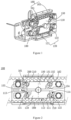
- a lock device 100 is used to lock a sliding door (not shown).
- the lock device 100 comprises a first lock portion 110 and a transmission portion 200.
- the transmission portion 200 can move relative to the first lock portion 110 along a predetermined path, so that the transmission portion 200 can bring the sliding door to move along the predetermined path to open or close the sliding door.
- the transmission portion 200 has a plurality of successively arranged mating portions for locking with the first lock portion 110.
- the first lock portion 110 has a first position in which the first lock portion 110 is locked with the transmission portion 200 and a second position in which the first lock portion 110 is released from the transmission portion 200.
- the transmission portion 200 may be locked in different positions along the predetermined path by matching the first lock portion 110 with different mating portions.
- the sliding door usually comprises one or more door leaves.
- a first door leaf of the sliding door may move as driven by the transmission portion 200, so as to cause the first door leaf to move in a direction of opening or closing the door.
- the first lock portion 110 releases the transmission portion 200, so that the transmission portion 200 could move along the predetermined path.
- the predetermined path refers to a movement path of the transmission portion 200 when it is driven. Along the predetermined path, the transmission portion 200 may bring the first door leaf to move in the opening or closing direction.
- the transmission portion 200 moves along the predetermined path
- the plurality of mating portions of the transmission portion 200 move synchronously with the transmission portion 200, so that the different mating portions could pass the first lock portion 110 successively, allowing the different mating portions to match with the first lock portion 110, respectively.
- the first lock portion 110 move to the first position, it could match with the mating portions and lock the transmission portion 200.
- the transmission portion 200 is in different positions of the predetermined path, so that the transmission portion 200 could be locked in different positions of the predetermined path. After the transmission portion 200 is locked, it will no longer be able to drive the first door leaf to move, so that the first door leaf could be locked in any position along the travel range of the first door leaf.
- the first door leaf could be locked not only in a fully open position or a fully closed position, but also in any partly-open position thereof, so that the first door leaf of the sliding door could be locked in the partly-open state stably.
- the transmission portion 200 is a transmission belt.
- the transmission portion 200 is a transmission belt
- the first door leaf is fixedly connected to the transmission belt. Accordingly, the transmission belt in motion will drive the movement of the first door leaf.
- the first lock portion 110 could comprise a plurality of clips and the mating portions may be in the form of hooks which match with the clips. When the transmission belt moves and brings the first door leaf to move, so will the plurality of hooks on the transmission belt.
- the first lock portion 110 can lock different hooks on the transmission belt via the clips, to inhibit the transmission belt from moving, thereby locking the first door leaf in different positions. As a result, it is possible to lock the first door leaf in any position along the travel range of the first door leaf.
- the transmission portion 200 can bring the mating portions to move relative to the first lock portion 110 along a straight path. That is to say, the first door leaf can move along the straight path together with the transmission portion 200.
- the first lock portion 110 can move along a path which is at an angle with the straight path. Due to the angle formed between the movement paths of the first lock portion 110 and the transmission portion 200, which may be a sharp angle or an obtuse angle, the first lock portion 110 may move towards or away from the transmission portion 200, causing the first lock portion 110 to lock with or separate from the mating portions and thus lock or release the transmission portion 200.
- the transmission portion 200 can bring the mating portions to move relative to the first lock portion 110 along the straight path, several different mating portions can pass the first lock portion 110 successively so that the different mating portions can match with the first lock portion 110.
- the transmission portion 200 is located in different positions of the predetermined path, so that the transmission portion 200 can be locked in different positions of the predetermined path.
- the first lock portion 110 and the mating portions match with each other in the way of one-way relative motion.
- the mating portions can move in a single direction relative to the first lock portion 110.
- the single direction may be a direction in which the first door leaf closes.
- the mating portions can only move along the closing direction of the first door leaf and cannot move along the opening direction of the first door leaf, so that the sliding door cannot be opened when locked, providing a good function of thievery and robbery prevention.
- the mating portions comprise a plurality of teeth 210 and tooth sockets between adjacent teeth 210.
- the first lock portion 110 comprises a plurality of first teeth 111, with a tooth socket 112 formed between adjacent first teeth 111.
- the first lock portion 110 is separated from the transmission portion 200, releasing the transmission portion 200 to cause the transmission portion 200 to move along the predetermined path.
- the teeth 210 and the tooth sockets of the transmission portion 200 move as well.
- the first lock portion 110 moves to the first position, the first lock portion 110 is engaged with the transmission portion 200, so that the teeth 210 can be blocked by the first teeth 111, thereby locking the transmission 200. Since the transmission portion 200 can move along the predetermined path, the different teeth 210 of the transmission portion 200 can pass the first lock portion 110 successively to be engaged with the first lock portion 110. When different teeth 210 are engaged with the first lock portion 110, the transmission portion 200 may be locked in different positions.
- the first lock portion 110 can be engaged with the transmission portion 200, which facilitates the first teeth 111 to block the teeth 210 of the transmission portion 200 so as to lock the transmission portion 200, thereby locking the first door leaf of the sliding door.
- the transmission belt with teeth 210 and tooth sockets as the transmission portion 200, when the transmission portion 200 moves, the plurality of teeth of the transmission portion 200 can pass the first lock portion 110 successively to lock the transmission portion 200 in different positions.
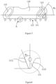
- each tooth 111 has, along the tooth thickness, a first surface 1111 and a second surface 1112 opposite to the first surface 1111.
- the first surface 1111 forms an angle ⁇ 1 , with a direction perpendicular to the moving direction of the first door leaf, in the range of 20° ⁇ 30°.
- the angle ⁇ 1 is 23°.
- the second surface 1112 has a first limitation part in the direction of the moving direction of the first door leaf. The first limitation part can limit the movement of the teeth 210 of the transmission portion 200, so that the teeth 210 of the transmission portion 200 cannot move beyond the second surface 1112 in a direction X1 toward the first surface 1111.
- the direction X1 that is, the direction from the second surface towards the first surface 1111, is the opening direction of the first door leaf.
- the first limitation part can limit the teeth 210 of the transmission portion 200 from moving beyond the second surface 1112 towards the first surface 1111.
- the first limitation part can limit the teeth 210 of the transmission portion 200 from moving in the opening direction X1 of the first door leaf, which means the first limitation part can limit the transmission part 200 from moving in the opening direction of the first door leaf. Therefore, when the first lock portion 110 is engaged with the transmission portion 200, the first limitation part can limit the first door leaf from being opened after it is locked. Therefore, the first lock portion 110 can lock the first door leaf reliably and keep the same in a locked position that is stable and not easily shakable.
- the second surface 1112 is a concave arc surface which defines the first limitation part.
- the transmission portion 200 when locked with the first lock portion 110, can hardly move in the opening direction X1 of the first door leaf. Accordingly, the first lock portion 110 can lock the first door leaf reliably and keep the same in a locked position that is stable and not easily shakable.
- the first surface 1111 is a bevel.
- the transmission portion 200 moves in the closing direction X2 of the first door leaf as well, and the teeth 210 of the transmission portion 200 may collide with the first surface 1111.
- the first surface 1111 is a bevel
- the surface of the tooth 210 close to the first surface 1111 is also made a bevel, so that the first surface 1111 and the surface of the tooth 210 close by can easily slide on each other. Accordingly, the tooth 210 can easily slide over the first surface 1111 and move in the closing direction X2 of the first door leaf. Therefore, the first surface 1111, when provided in the form of a bevel, allows the transmission portion 200 to easily move in the closing direction X2 of the first door leaf when the first lock portion 110 is locked with the transmission portion 200.
- the first lock portion 110 when the first lock portion 110 transfers between the first position and the second position, the first lock portion 110 moves close to or away from the transmission portion 200.
- the first lock portion 110 moves towards the first position so as to lock the transmission portion 200.
- the first lock portion moves away from the transmission portion 200 so as to release the transmission portion 200.
- the lock device 100 further comprises a first guiding assembly 120.
- the first guiding assembly 120 is used to guide the movement direction of the first lock portion 110, so that the first lock portion 110 can move to the first position or the second position precisely. As a result, the first lock portion 110 can lock or release the transmission portion 200 precisely.
- the first guiding assembly 120 comprises a first guiding pin 121 and a second guiding pin 122, the positions of both being fixed .
- the first guiding pin 121 and the second guiding pin 122 may be fixed on a block through threaded connection.
- Other ways can also be used to fix the first guiding pin 121 and the second guiding pin 122, which is not specifically limited in this embodiment.
- the first lock portion 110 is provided with a first guiding slot 113 and a second guiding slot 114, wherein the first guiding pin 121 is located in the first guiding slot 113 and the second guiding pin 122 is located in the second guiding slot 114.
- first guiding pin 121 and the second guiding pin 122 are fixed, only the movement of the first lock portion 110 can cause the movements of the first guiding pin 121 and the second guiding pin 122 relative to the first lock portion 110, respectively. Since the first guiding pin 121 is located in the first guiding slot 113 and the second guiding pin 122 is located in the second guiding slot 114, the first guiding pin 121 restricts the first lock portion 110 to only move in a direction parallel to the extending direction of the first guiding slot 113, and the second guiding pin 122 restricts the first lock portion 110 to only move in a direction parallel to the extending direction of the second guiding slot 114.
- the first lock portion 110 can only move in the direction parallel to the extending directions of the first guiding slot 113 and the second guiding slot 114. Accordingly, the first guiding assembly 120 has a function of guiding the movement direction of the first lock portion 110. As a result, when the first lock portion 110 moves in a direction parallel to the extending direction of the first guiding slot 113 and the extending direction of the second guiding slot 114, the first lock portion 110 can move to the first position or second position precisely, thereby precisely locking or releasing the transmission portion 200.
- the first lock portion 110 has a plurality of alternating first teeth 111 and first tooth sockets.
- the guiding function of the first guiding assembly 120 can guide the movement direction of the first lock portion 110, so that the first lock portion 110 can move to the first position precisely to cause the first lock portion 110 to engage with the transmission portion 200 precisely.
- the first lock portion 110 can lock the first door leaf reliably.
- the extending direction of the first guiding slot 113 and the movement direction of the first door leaf form an angle, ⁇ 2 , which is ranged from 40° to 60°.
- ⁇ 2 which is ranged from 40° to 60°.
- the first lock portion 110 achieves a good effect of locking.
- the angle ⁇ 2 is 50°
- the first guiding pin 121 and the second guiding pin 122 can block the movement of the first lock portion 110 with a better effect when the first locking portion 110 locks the transmission portion 200, making it even harder for the first lock portion 110 to move in the movement direction of the first door leaf, thus a good effect of locking of the first lock portion 110.
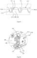
- the lock device further comprises a first linkage assembly 130 which can bring the first lock portion 110 to move with the guiding of the first guiding assembly 120, so that the first lock portion 110 can transfer between the first position and the second position to lock or release the transmission portion 200 precisely.
- the first linkage assembly 130 comprises a rotatable first linkage portion 131 and a second linkage portion 132.
- the first linkage portion 131 may be a rotary rod as shown in FIG.6 and the second linkage portion 132 may be a pin as shown in FIG.6 .
- the first linkage portion 131 is provided with a fifth guiding slot 133, in which the second linkage portion 132 is located.
- the second linkage portion 132 is fixedly connected with the first lock portion 110.
- the fifth guiding slot 133 also rotates along.
- the rotation direction of the first linkage portion 131 is perpendicular to the extending direction of the fifth guiding slot 133. Since the second linkage portion 132 is located in the fifth guiding slot 133, the second linkage portion 132 can rotate with the rotation of the fifth guiding slot 133.
- the second linkage portion 132 can also move in the extending direction of the fifth guiding slot 133.
- the rotation of the first linkage portion 131 brings the second linkage portion 132 to move.
- the movement of the second linkage portion 132 can bring the first lock portion 110 to move, which drives the first lock portion 110 to move. Therefore, the first linkage portion 131 rotates to bring the second linkage portion 132 to move and the second linkage portion 132 brings the first lock portion 110 to move, while the first guiding assembly 120 guides the movement direction of the first lock portion 110. As a result, the first lock portion 110 can move to the first position or the second position precisely, which causes the first lock portion 110 to lock or release the transmission portion 200.
- the lock device further comprises a second lock portion 150.
- the transmission portion 200 can drive the movement of a second door leaf (not shown) of the sliding door.
- the transmission portion 200 can move along the predetermined path relative to the second lock portion 150, so that the transmission portion 200 can bring the sliding door to move along the predetermined path to open or close the sliding door.
- the transmission portion 200 has a plurality of successively arranged mating portions for locking with the second lock portion 150.
- the second lock portion 150 has a third position in which the second lock portion 150 is locked with the transmission portion 200 and a fourth position in which the second lock portion 150 is released from the transmission portion.
- the transmission portion 200 may be locked in different positions along the predetermined path by matching the second lock portion 150 with different mating portions.
- the second door leaf of the sliding door may move as driven by the transmission portion 200, so as to cause the second door leaf to move in a direction of opening or closing the door.
- the second lock portion 150 When the second lock portion 150 is in the fourth position, the second lock portion 150 releases the transmission portion 200, so that the transmission portion 200 could move along the predetermined path.
- the predetermined path means a movement path of the transmission portion 200 when it is driven. Along the predetermined path, the transmission portion 200 may bring the second door leaf to move in the opening or closing direction.
- the transmission portion 200 moves along the predetermined path
- the plurality of mating portions of the transmission portion 200 move synchronously with the transmission portion 200, so that the different mating portions could pass the second lock portion 150 successively, allowing the different mating portion to match with the second lock portion 150 respectively.
- the second lock portion 150 move to the third position, it could match with the mating portions and lock the transmission portion 200.
- the transmission portion 200 is in different positions of the predetermined path, so that the transmission portion 200 could be locked in different positions of the predetermined path. After the transmission portion 200 is locked, it will no longer be able to drive the second door leaf to move, so that the second door leaf could be locked in any position along the travel range of the second door leaf.
- the second door leaf could be locked not only in a fully open position or a fully closed position, but also in any partly-open position of the second door leaf, so that the second door leaf of the sliding door could be locked in the partly-open state stably.
- the transmission portion 200 is a transmission belt
- the second door leaf is fixedly connected to the transmission belt.
- the second lock portion 150 could comprise a plurality of clips and the mating portions may be in the form of hooks which match with the clips.
- the second lock portion 150 can lock different hooks on the transmission belt via the clips, to inhibit the transmission belt from moving, thereby locking the second door leaf in different positions. As a result, it is possible to lock the second door leaf in any position along the travel range of the second door leaf.
- the transmission portion 200 is an annular transmission belt and is fixedly connected with the first door leaf and the second door leaf, respectively.
- the annular transmission belt moves, the annular transmission belt can reciprocate along the circumferential direction of the annular transmission belt.
- the first door leaf and the second leaf door can move simultaneously when the transmission portion 200 moves, and be locked simultaneously when the transmission portion 200 is locked.
- the transmission portion 200 comprises a first portion and a second portion independent of each other.
- the first portion and the second portion may be transmission belts independent of each other.
- the movement of the first portion can bring the first door leaf to move.
- the first portion can match with the first lock portion 110, so that the first lock portion 110 locks the first portion, thereby locking the first door leaf.
- the movement of the second portion can bring the second door leaf to move.
- the second portion brings the second door leaf to move to different positions
- the second portion can match with the second lock portion 150, so that the second locks portion 150 lock the second portion, , thereby locking the second door leaf.
- the locking state of the first door leaf and the second door leaf could be independent of each other due to the independent movements of the first portion and the second portion.
- the transmission portion 200 can bring the mating portions to move relative to the second lock portion 150 along the straight path. That is to say, the second door leaf can move along the straight path together with the transmission portion 200.
- the second lock portion 150 can move along a path which is at an angle with the straight path. Due to the angle formed between the movement paths of the first lock portion 110 and the transmission portion 200, which could be a sharp angle or an obtuse angle, the second lock portion 150 may move towards or away from the transmission portion 200, causing the second lock portion 150 to lock with or separate from the mating portions, and thus lock or release the transmission portion 200.
- the transmission portion 200 can bring the mating portions to move relative to the second lock portion 150 along the straight path, several different mating portions can pass the second lock portion 150 successively, so that the different mating portions can match with the second lock portion 150.
- the transmission portion 200 is located in different positions of the predetermined path, so that the transmission portion 200 could be locked in different positions of the predetermined path.
- the second lock portion 150 and the mating portions can match each other in the way of one-way relative motion.
- the mating portions can move in a single direction relative to the second lock portion 150.
- the single direction may be a direction in which the second door leaf closes.
- the mating portions can only move along a closing direction of the second door leaf and cannot move along the opening direction of the second door leaf, so that the sliding door cannot be opened when locked, providing a good function of thievery and robbery prevention.
- the mating portions comprise a plurality of teeth 210 and tooth sockets between adjacent teeth 210.
- the second lock portion 150 comprises a plurality of second teeth 151, with a second tooth socket 152 formed between adjacent second teeth 151.
- the second lock portion 150 is separated from the transmission portion 200, releasing the transmission portion 200, to cause the transmission portion 200 to move along the predetermined path.
- the teeth 210 and the tooth sockets of the transmission portion 200 move as well.
- the second lock portion 150 moves to the third position, the second lock portion 150 is engaged with the transmission portion 200, so that the teeth 210 of the transmission portion 200 can be blocked by the second teeth 151, thereby locking the transmission 200. Since the transmission portion 200 can move along the predetermined path, the different teeth 210 of the transmission portion 200 can pass the second lock portion 150 successively to be engaged with the second lock portion 150. When different teeth 210 are engaged with the second lock portion 150, the transmission portion 200 may be locked in different positions.
- the second lock portion 150 can be engaged with the transmission portion 200, which facilitate the second teeth 151 to block the teeth 210 of the transmission portion 200 so as to lock the transmission portion 200, thereby locking the first door leaf of the sliding door.
- the transmission belt with teeth 210 and tooth sockets as the transmission portion 200, when the transmission portion 200 moves, the plurality of teeth of the transmission portion 200 can pass the second lock portion 150 successively to lock the transmission portion 200 in different positions.
- each second tooth 151 has, along the tooth thickness, a third surface and a fourth surface opposite to the third surface.
- the third surface forms an angle with the direction perpendicular to the moving direction of the second door leaf, which could be in the range of 20° ⁇ 30°. Preferably, the angle is 23°.
- the fourth surface has a second limitation part in the direction of the moving direction of the second door leaf. The second limitation part can limit the movement of the teeth 210 of the transmission portion 200, so that the teeth 210 of the transmission portion 200 cannot move beyond the fourth surface in a movement direction toward the third surface.
- the direction from the fourth surface towards the third surface is the opening direction of the second door leaf.
- the second limitation part could limit the teeth 210 of the transmission portion 200 from moving beyond the fourth surface towards the third surface.
- the first limitation part could limit the teeth 210 of the transmission portion 200 from moving in the opening direction of the second door leaf, which means the second limitation part can limit the transmission part 200 from moving in the opening direction of the second door leaf. Therefore, when the second lock portion 150 is engaged with the transmission portion 200, the second limitation part can limit the second door leaf from being opened after it is locked. Therefore, the second lock portion 150 can lock the second door leaf reliably and the second door leaf could be kept in the locked position stably and cannot be easy to shake.
- the fourth surface is a concave arc surface, which defines the second limitation part.
- the second lock portion 150 locks the transmission portion 200
- the second lock portion 150 is engaged with the transmission portion 200.
- the teeth 210 of the transmission portion 200 are engaged between the second teeth 151, and vice versa. If the second door leaf is made to slide by an applied force in the opening direction of the second door leaf, the teeth 210 of the transmission portion 200 may collide with the fourth surface. Due to the concave of the fourth surface, a sharp corner B formed at the intersection of the tooth top surface of the tooth 210 and the surface of the tooth 210 close to the fourth surface will abut against the fourth surface, so that the tooth 210 can hardly move beyond the fourth surface in the direction towards the third surface.
- the transmission portion 200 when locked with the second lock portion 150, can hardly move in the opening direction of the second door leaf. Accordingly, the second lock portion 150 can lock the second door leaf reliably and keep the same in a locked position that is stable and not easily shakable.
- the third surface is a bevel.
- the transmission portion 200 moves in the closing direction of the second door leaf as well, and the teeth 210 of the transmission portion 200 may collide with the third surface.
- the third surface is a bevel
- the surface of the tooth 210 close to the third surface is also made a bevel, so that the third surface and the surface of the tooth 210 close by can easily slide on each other. Accordingly, the tooth 210 can easily slide over the third surface and move in the closing direction of the second door leaf. Therefore, the third surface, when provided in the form of a bevel, allows the transmission portion 200 to easily move in the closing direction of the first door leaf when the second lock portion 150 is locked with the transmission portion 200.
- the second lock portion 150 when the second lock portion 150 transfers between the third position and the fourth position, the second lock portion 150 moves close to or away from the transmission portion 200.
- the second lock portion 150 moves towards the third position to lock the transmission portion 200.
- the second lock portion 150 moves towards the fourth position, the second lock portion 150 moves away from the transmission portion 200 to release the transmission portion 200.
- the lock device 100 further comprises a second guiding assembly 160.
- the second guiding assembly 160 is used to guide the movement direction of the second lock portion 150, so that the second lock portion 150 could move to the third position or the fourth position precisely. As a result, the second lock portion 150 can lock or release the transmission portion 200 precisely.
- the second guiding assembly 160 comprises a third guiding pin 161 and a fourth guiding pin 162, the positions of both being fixed.
- the third guiding pin 161 and the fourth guiding pin 162 may be fixed on a block through threaded connection.
- Other ways can also be used to fix the third guiding pin 161 and the fourth guiding pin 162, which is not specifically limited in this embodiment.
- the second lock portion 150 is provided with a third guiding slot 153 and a fourth guiding slot 154, wherein the third guiding pin 161 is located in the third guiding slot 153 and the fourth guiding pin 162 is located in the fourth guiding slot 154.
- the third guiding pin 161 and the fourth guiding pin 162 are fixed, only the movement of the second lock portion 150 can cause the movements of the third guiding pin 161 and the fourth guiding pin 162 relative to the second lock portion 150 respectively. Since the third guiding pin 161 is located in the third guiding slot 153 and the fourth guiding pin 162 is located in the fourth guiding slot 154, the third guiding pin 161 restricts the second lock portion 150 to only move in a direction parallel to the extending direction of the third guiding slot 153, and the fourth guiding pin 162 restricts the second lock portion 150 to only move in a direction parallel to the extending direction of the fourth guiding slot 154.
- the second lock portion 150 can only move in the direction parallel to the extending directions of the third guiding slot 153 and the fourth guiding slot 154. Accordingly, the second guiding assembly 160 has a function of guiding the movement direction of the second lock portion 150. As a result, when the second lock portion 150 moves in a direction parallel to the extending direction of the third guiding slot 153 and the extending direction of the fourth guiding slot 154, the second lock portion 150 can move to the third position or fourth position precisely, thereby precisely locking or releasing the transmission portion 200. Specifically, in this embodiment, the second lock portion 150 has a plurality of alternating second teeth 151 and second tooth sockets 152.
- the guiding function of the second guiding assembly 160 can guide the movement direction of the second lock portion 150, so that the second lock portion 150 can move to the third position precisely to cause the second lock portion 150 to engage with the transmission portion 200 precisely.
- the second lock portion 150 can lock the second door leaf reliably.
- the extending direction of the third guiding slot 153 and the movement direction of the first door leaf form an angle which could be ranged from 40° to 60°.
- the third guiding pin 161 and the fourth guiding pin 162 can block the movement of the second lock portion 150, since the third guiding pin 161 and could block the fourth guiding pin 162 could block the inner wall of the third guiding slot 153 and the fourth guiding slot 154, respectively.
- the second lock portion 150 can hardly move in the movement direction of the second door leaf, , making it extremely difficult to open the first door leaf.
- the second lock portion 150 achieves a good effect of locking.
- the third guiding pin 161 and the fourth guiding pin 162 can block the movement of the second lock portion 150 with a better effect when the second locking portion 150 locks the transmission portion 200, making it even harder for the second lock portion 150 to move in the direction of the movement direction of the second door leaf, thus a good effect of locking of the second lock portion 150.
- the lock device 100 further comprises a second linkage assembly 170 which can bring the second lock portion 150 to move with the guiding of the second guiding assembly 160, so that the second lock portion 150 can transfer between the third position and the fourth position to lock or release the transmission portion 200 precisely.
- the second linkage assembly 170 comprises a rotatable third linkage portion 171 and a fourth linkage portion 172.
- the third linkage portion 171 may be a rotary rod as shown in FIG.6 and the fourth linkage portion 172 may be a pin as shown in FIG.6 .
- the third linkage portion 171 is provided with a sixth guiding slot 173 in which the fourth linkage portion 172 is located.
- the fourth linkage portion 172 is fixedly connected with the second lock portion 150.
- the sixth guiding slot 173 also rotates along.
- the rotation direction of the third linkage portion 171 is perpendicular to the extending direction of the sixth guiding slot 173. Since the fourth linkage portion 172 is located in the sixth guiding slot 173, the fourth linkage portion 172 can rotate with the rotation of the sixth guiding slot 173.
- the fourth linkage portion 172 can also move in the extending direction of the sixth guiding slot 173.
- the rotation of the third linkage portion 171 brings the fourth linkage portion 172 to move.
- the movement of the fourth linkage portion 172 can bring the second lock portion 150 to move, which drives the second lock portion 150 to move. Therefore, the third linkage portion 171 rotates to bring the fourth linkage portion 172 to move and the fourth linkage portion 172 brings the second lock portion 150 to move while the second guiding assembly 160 guides the movement direction of the second lock portion 150. As a result, the second lock portion 150 can move to the third position or the fourth position precisely, which causes the second lock portion 150 to lock or release the transmission portion 200.
- the surface of the second lock portion 150 close to the transmission portion of the second door leaf is located on a side of the second lock portion 150 which is away from the first lock portion 110.
- the surface of the first lock portion 110 close to the transmission portion 200 is located on a side of the first lock portion 110 which is away from the second locking portion 150.
- the first lock portion 110 moves in a direction away from the second lock portion 150.
- the second lock portion 150 moves close to the transmission portion 200
- the second lock portion 150 moves in a direction away from the first lock portion 110.
- the movement direction of the first lock portion 110 is opposite to that of the second lock portion 150.
- the surface of the second lock portion 150 close to the transmission portion of the second door leaf may also be located on a side of the second lock portion 150 which is close to the first lock portion 110.
- the surface of the first lock portion 110 close to the transmission portion 200 may also be located on the side of the first lock portion 110 which is close to the second locking portion 150.
- the lock device 100 further comprises a first pin 180.
- the first linkage portion 131 is fixedly connected with the third linkage portion 171.
- the first linkage portion 131 and the third linkage portion 171 may be a rotary bar that is integrally formed. Therefore, when the first linkage portion 131 moves, the third linkage portion 171 moves synchronously with the first linkage portion 131. Since the fifth guiding slot 133 is located on one side of the first pin 180 while the sixth guiding slot 173 is located on the other side of the first pin 180, the fifth guiding slot 133 and the sixth guiding slot 173 have the same extending direction.
- the second linkage portion 132 and the fourth linkage portion 172 have opposite movement directions, and in turn opposite movement directions of the first lock portion 110 and the second lock portion 150. Therefore, when the first linkage portion 131 and the third linkage portion 171 are rotated, the first lock portion 110 and the second lock portion 150 can simultaneously move in opposite directions. Therefore, when the first lock portion 110 locks the first door leaf, the second lock portion 150 locks the second door leaf at the same time. Similarly, when the first lock portion 110 releases the first door leaf, the second lock portion 150 releases the second door leaf at the same time.
- the lock device 100 further comprises a first supporting portion 190, wherein the first pin 180 is adjustably connected with the first supporting portion 190.
- the first pin 180 has an adjustable position on the first supporting portion, so that it is possible to adjust the positions of the first linkage portion 131 and the third linkage portion 171 in order to adjust the positions of the first lock portion 110 and the second lock portion 150.
- the position of the first pin 180 in a movement direction of the first door leaf may be adjusted, so as to allow the first lock portion 110 to be engaged with the transmission portion 200 precisely.
- the position of the first pin 180 in a movement direction of the second door leaf may be adjusted, so as to allow the second lock portion 150 to be engaged with the transmission portion 200 precisely.
- the first supporting portion 190 may be provided with a seventh guiding slot, the extending direction of which being parallel to the sliding direction of the first door leaf and the second door leaf.
- the first pin 180 is located in the seventh guiding slot. By moving the first pin 180 along the extending direction of the seventh guiding slot., the position of the first pin 180 in the sliding direction of the first door leaf and the second door leaf may be adjusted, so that the first lock portion 110 and the second lock portion 150can be precisely engaged with the transmission portion 200, respectively.
- the lock device 100 further comprises a driving portion (not shown) configurated to drive the first linkage portion 131 and the third linkage portion 171 to rotate.
- the driving portion may be a solenoid valve.
- the type of locking may be fail safe locking, fail secure locking, or bi-stable locking.
- a system for sliding door comprises a lock device 100 as in any embodiment mentioned above, One or more door leaves are fixedly connected with a transmission portion 200 of the sliding door system.
- the lock device 100 comprises a first lock portion 110 and the transmission portion 200.
- the transmission portion may move relative to the first lock portion 110 along the predetermined path, so that the transmission portion 200 may bring the sliding door to move along the predetermined path to open or close the sliding door.
- the transmission portion 200 has a plurality of successively arranged mating portions which can lock with the first lock portion 110.
- the first lock portion 110 has a first position in which the first lock portion 110 is locked with the transmission portion 200 and a second position in which the first lock portion 110 is released from the transmission portion 200.
- the transmission portion 200 may be locked in different positions along the predetermined path by matching the first lock portion 110 with different mating portions.
- the sliding door may be locked not only in its open and closed position, but also in any partly-open position of the sliding door. Therefore, the sliding door may be locked in the partly-open state stably.
Landscapes
- Engineering & Computer Science (AREA)
- Mechanical Engineering (AREA)
- Lock And Its Accessories (AREA)
- Power-Operated Mechanisms For Wings (AREA)
Applications Claiming Priority (2)
| Application Number | Priority Date | Filing Date | Title |
|---|---|---|---|
| CN201810024268.7A CN108131063B (zh) | 2018-01-10 | 2018-01-10 | 用于锁定滑动门的锁定装置 |
| PCT/EP2018/085405 WO2019137752A1 (en) | 2018-01-10 | 2018-12-18 | Locking device for sliding door |
Publications (3)
| Publication Number | Publication Date |
|---|---|
| EP3737814A1 EP3737814A1 (en) | 2020-11-18 |
| EP3737814B1 true EP3737814B1 (en) | 2024-03-06 |
| EP3737814C0 EP3737814C0 (en) | 2024-03-06 |
Family
ID=62400586
Family Applications (1)
| Application Number | Title | Priority Date | Filing Date |
|---|---|---|---|
| EP18826594.6A Active EP3737814B1 (en) | 2018-01-10 | 2018-12-18 | Locking device for sliding door |
Country Status (5)
| Country | Link |
|---|---|
| US (1) | US11739566B2 (zh) |
| EP (1) | EP3737814B1 (zh) |
| CN (1) | CN108131063B (zh) |
| ES (1) | ES2975358T3 (zh) |
| WO (1) | WO2019137752A1 (zh) |
Families Citing this family (9)
| Publication number | Priority date | Publication date | Assignee | Title |
|---|---|---|---|---|
| CN108986675B (zh) * | 2018-07-21 | 2020-07-07 | 福建省海佳集团股份有限公司 | 一种户外裸装显示屏 |
| DE102019108274B4 (de) * | 2019-03-29 | 2020-11-05 | Dormakaba Deutschland Gmbh | Verfahren zum Betrieb einer Schiebetüranlage und Schiebetüranlage |
| DE102019108273B4 (de) * | 2019-03-29 | 2021-06-24 | Dormakaba Deutschland Gmbh | Verriegelungseinrichtung für eine Schiebetüranlage und Schiebetüranlage |
| DE102019108270A1 (de) * | 2019-03-29 | 2020-10-01 | Dormakaba Deutschland Gmbh | Schiebetüranlage |
| DE102019108275B4 (de) * | 2019-03-29 | 2022-12-01 | Dormakaba Deutschland Gmbh | Linearmotor zum Bewegen eines Verriegelungsmittels, Verriegelungseinrichtung für eine Schiebetüranlage und eine solche Schiebetüranlage |
| DE102020113394B4 (de) | 2020-05-18 | 2024-08-08 | Dormakaba Deutschland Gmbh | Verriegelungseinrichtung für eine schiebetüranlage und schiebetüranlage |
| DE102020113395A1 (de) | 2020-05-18 | 2021-11-18 | Dormakaba Deutschland Gmbh | Verriegelungseinrichtung für eine schiebetüranlage und schiebetüranlage |
| CN112554686B (zh) * | 2020-12-11 | 2022-03-15 | 合肥工业大学 | 一种基于棘轮和齿轮齿条结构的推拉窗安全锁具 |
| CN115354929B (zh) * | 2022-07-13 | 2023-06-30 | 江苏德普尔门控科技有限公司 | 一种自动平移门位置锁定用控制装置 |
Citations (1)
| Publication number | Priority date | Publication date | Assignee | Title |
|---|---|---|---|---|
| FR2853683A1 (fr) * | 2003-04-08 | 2004-10-15 | Porte Automatique Service | Dispositif de portail coulissant autoportant motorise |
Family Cites Families (33)
| Publication number | Priority date | Publication date | Assignee | Title |
|---|---|---|---|---|
| DE1131553B (de) * | 1960-01-12 | 1962-06-14 | Dieter Rau | Vorrichtung zum Bewegen, insbesondere OEffnen und/oder Schliessen, von waagerecht schiebbaren Verschliess- einrichtungen, vorzugsweise von Tuerfluegeln |
| US4763385A (en) * | 1985-07-05 | 1988-08-16 | Geze Gmbh | Door closure transmission utilizing an eccentric pinion |
| DE4206565C2 (de) * | 1992-03-02 | 1995-01-19 | Marantec Antrieb Steuerung | Schiebetor |
| US5285596A (en) | 1992-11-13 | 1994-02-15 | Kinsey Kenneth M | Door closure apparatus |
| CN2152042Y (zh) * | 1992-12-06 | 1994-01-05 | 陈铁山 | 自动关窗风钩 |
| DE4415708C1 (de) * | 1994-05-04 | 1995-07-13 | Dorma Gmbh & Co Kg | Vorrichtungen zur Verriegelung einer Schiebetür |
| JP3835562B2 (ja) * | 1995-10-22 | 2006-10-18 | 美和ロック株式会社 | 引戸用電気錠 |
| DE19650136B4 (de) * | 1996-12-03 | 2006-06-29 | Brose Schließsysteme GmbH & Co.KG | Kraftfahrzeug-Türschloß o. dgl. mit Freilauf |
| DE19700859B4 (de) * | 1997-01-13 | 2004-07-22 | Geze Gmbh | Tür- oder Fensteranlage mit einer Verriegelungsvorrichtung |
| US6139073A (en) * | 1998-08-31 | 2000-10-31 | Westinghouse Air Brake Company | Lock assembly |
| US6446389B1 (en) * | 2000-04-14 | 2002-09-10 | Westinghouse Air Brake Technologies Corporation | Tandem sliding door operator |
| US6079767A (en) * | 1999-06-29 | 2000-06-27 | Daimlerchrysler Corporation | Power sliding door for a motor vehicle |
| US6256930B1 (en) * | 1999-06-29 | 2001-07-10 | Daimlerchrysler Corporation | Power sliding door-gear drive |
| DE10107046C2 (de) * | 2001-02-13 | 2003-05-28 | Dorma Gmbh & Co Kg | Gleitschienenschließer |
| US6688042B2 (en) * | 2001-05-05 | 2004-02-10 | Westinghouse Air Brake Technologies Corporation | Central lock mechanism |
| DE102004023927C5 (de) | 2004-05-12 | 2010-05-06 | Dorma Gmbh + Co. Kg | Schiebetürsystem mit einer in einem Kämpfer angeordneten Antriebsvorrichtung |
| CN2802008Y (zh) * | 2005-06-14 | 2006-08-02 | 葛现光 | 自锁式卷帘门锁 |
| DE102005058939B4 (de) * | 2005-12-09 | 2008-03-13 | Sommer Antriebs- Und Funktechnik Gmbh | Antriebsvorrichtung für ein Schiebetor und Verfahren zu dessen Montage |
| JP2008127772A (ja) * | 2006-11-17 | 2008-06-05 | Hoshino Kk | 引き違い戸の補助錠 |
| CN101275450B (zh) | 2008-03-27 | 2010-06-23 | 庄子平 | 一种推拉门窗的锁具的主钩锁及锁具 |
| JP5403327B2 (ja) * | 2009-01-27 | 2014-01-29 | 富士電機株式会社 | 車両用引戸開閉装置 |
| IT1392935B1 (it) * | 2009-02-23 | 2012-04-02 | Caimi Export Spa | Dispositivo per la movimentazione di ante scorrevoli |
| CN101566026B (zh) * | 2009-03-25 | 2012-07-18 | 王亚运 | 一种自动门锁 |
| AT508230A1 (de) * | 2009-04-23 | 2010-11-15 | Knorr Bremse Gmbh | Ein- oder zweiflügelige schiebe-, schwenkschiebe- oder taschentür |
| CN201411980Y (zh) * | 2009-05-27 | 2010-02-24 | 鼎鑫(宁波)合金制造有限公司 | 门窗锁具 |
| US8931813B2 (en) * | 2009-06-04 | 2015-01-13 | A.L. Hansen Manufacturing Co. | Rotary lock providing positive latching indicia |
| JP4895318B2 (ja) * | 2010-02-24 | 2012-03-14 | 株式会社中尾製作所 | 引込装置 |
| ITBO20130044A1 (it) * | 2013-01-31 | 2014-08-01 | Gsg Int Spa | Dispositivo anti falsa manovra per porte o finestre scorrevoli. |
| JP6180806B2 (ja) * | 2013-06-13 | 2017-08-16 | ナブテスコ株式会社 | ドア開閉装置 |
| CN105545139B (zh) | 2016-01-22 | 2017-08-25 | 南京康尼机电股份有限公司 | 自动移门系统 |
| CN107100498A (zh) * | 2017-04-07 | 2017-08-29 | 宁波中车时代传感技术有限公司 | 一种单开式屏蔽门 |
| WO2019087370A1 (ja) * | 2017-11-02 | 2019-05-09 | 富士電機株式会社 | ドア開閉装置 |
| CN208089032U (zh) * | 2018-01-10 | 2018-11-13 | 亚萨合莱自动门系统有限公司 | 用于锁定滑动门的锁定装置以及滑动门系统 |
-
2018
- 2018-01-10 CN CN201810024268.7A patent/CN108131063B/zh active Active
- 2018-12-18 WO PCT/EP2018/085405 patent/WO2019137752A1/en unknown
- 2018-12-18 EP EP18826594.6A patent/EP3737814B1/en active Active
- 2018-12-18 US US16/959,393 patent/US11739566B2/en active Active
- 2018-12-18 ES ES18826594T patent/ES2975358T3/es active Active
Patent Citations (1)
| Publication number | Priority date | Publication date | Assignee | Title |
|---|---|---|---|---|
| FR2853683A1 (fr) * | 2003-04-08 | 2004-10-15 | Porte Automatique Service | Dispositif de portail coulissant autoportant motorise |
Also Published As
| Publication number | Publication date |
|---|---|
| CN108131063B (zh) | 2019-09-06 |
| CN108131063A (zh) | 2018-06-08 |
| US11739566B2 (en) | 2023-08-29 |
| EP3737814A1 (en) | 2020-11-18 |
| US20210032905A1 (en) | 2021-02-04 |
| EP3737814C0 (en) | 2024-03-06 |
| ES2975358T3 (es) | 2024-07-04 |
| WO2019137752A1 (en) | 2019-07-18 |
Similar Documents
| Publication | Publication Date | Title |
|---|---|---|
| EP3737814B1 (en) | Locking device for sliding door | |
| US10822857B2 (en) | Retrofittable motorized gear sliding window or door system | |
| KR102060564B1 (ko) | 양문형 슬라이딩 도어 시스템 | |
| US12024928B2 (en) | Multi-point locking system | |
| US7387076B2 (en) | Locking system for a door of an enclosure | |
| EP2735677B1 (en) | Door/window comprising an operating system with multiple locking points | |
| CN110573688A (zh) | 用于机动车的锁 | |
| US10041287B2 (en) | Secondary retention device for transit door | |
| US20080256872A1 (en) | Sliding Door System Comprising a Drive Device Located in a Transom | |
| US20230366241A1 (en) | Sliding door | |
| CN111433104B (zh) | 用于锁定屏蔽门的门扇的系统 | |
| US10995538B2 (en) | Retrofittable motorized pulley sliding window or door system | |
| AU2014223296B2 (en) | Folding door latch | |
| EP2407618B1 (en) | Snap-closing device for doors | |
| EP3702567A1 (en) | Burglary-preventing system | |
| US345048A (en) | Oes op one-thied to samuel baeeett | |
| US1630913A (en) | Swing-sash latching fixture | |
| US9605453B1 (en) | Door system and control | |
| EP0329039A1 (de) | Einbruchsicherung, insbesondere für ein Garagentor | |
| WO2022054026A1 (en) | Lock | |
| GB2486473A (en) | Locking Mechanism | |
| US20190003230A1 (en) | Device for opening and closing an outwardly opening pivoting wing | |
| WO2021044342A1 (en) | Lock | |
| EP1288421B1 (en) | Mechanism for actuating sliding doors | |
| WO2007009993A3 (en) | Safety frame for doors and windows |
Legal Events
| Date | Code | Title | Description |
|---|---|---|---|
| STAA | Information on the status of an ep patent application or granted ep patent |
Free format text: STATUS: UNKNOWN |
|
| STAA | Information on the status of an ep patent application or granted ep patent |
Free format text: STATUS: THE INTERNATIONAL PUBLICATION HAS BEEN MADE |
|
| PUAI | Public reference made under article 153(3) epc to a published international application that has entered the european phase |
Free format text: ORIGINAL CODE: 0009012 |
|
| STAA | Information on the status of an ep patent application or granted ep patent |
Free format text: STATUS: REQUEST FOR EXAMINATION WAS MADE |
|
| 17P | Request for examination filed |
Effective date: 20200806 |
|
| AK | Designated contracting states |
Kind code of ref document: A1 Designated state(s): AL AT BE BG CH CY CZ DE DK EE ES FI FR GB GR HR HU IE IS IT LI LT LU LV MC MK MT NL NO PL PT RO RS SE SI SK SM TR |
|
| AX | Request for extension of the european patent |
Extension state: BA ME |
|
| RIN1 | Information on inventor provided before grant (corrected) |
Inventor name: ZHANG, JEFF Inventor name: LIU, JACK |
|
| DAV | Request for validation of the european patent (deleted) | ||
| DAX | Request for extension of the european patent (deleted) | ||
| STAA | Information on the status of an ep patent application or granted ep patent |
Free format text: STATUS: EXAMINATION IS IN PROGRESS |
|
| 17Q | First examination report despatched |
Effective date: 20220215 |
|
| GRAP | Despatch of communication of intention to grant a patent |
Free format text: ORIGINAL CODE: EPIDOSNIGR1 |
|
| STAA | Information on the status of an ep patent application or granted ep patent |
Free format text: STATUS: GRANT OF PATENT IS INTENDED |
|
| INTG | Intention to grant announced |
Effective date: 20231016 |
|
| GRAS | Grant fee paid |
Free format text: ORIGINAL CODE: EPIDOSNIGR3 |
|
| GRAA | (expected) grant |
Free format text: ORIGINAL CODE: 0009210 |
|
| STAA | Information on the status of an ep patent application or granted ep patent |
Free format text: STATUS: THE PATENT HAS BEEN GRANTED |
|
| AK | Designated contracting states |
Kind code of ref document: B1 Designated state(s): AL AT BE BG CH CY CZ DE DK EE ES FI FR GB GR HR HU IE IS IT LI LT LU LV MC MK MT NL NO PL PT RO RS SE SI SK SM TR |
|
| REG | Reference to a national code |
Ref country code: GB Ref legal event code: FG4D |
|
| REG | Reference to a national code |
Ref country code: CH Ref legal event code: EP |
|
| REG | Reference to a national code |
Ref country code: DE Ref legal event code: R096 Ref document number: 602018066317 Country of ref document: DE |
|
| REG | Reference to a national code |
Ref country code: IE Ref legal event code: FG4D |
|
| U01 | Request for unitary effect filed |
Effective date: 20240405 |
|
| U07 | Unitary effect registered |
Designated state(s): AT BE BG DE DK EE FI FR IT LT LU LV MT NL PT SE SI Effective date: 20240412 |
|
| REG | Reference to a national code |
Ref country code: ES Ref legal event code: FG2A Ref document number: 2975358 Country of ref document: ES Kind code of ref document: T3 Effective date: 20240704 |
|
| PG25 | Lapsed in a contracting state [announced via postgrant information from national office to epo] |
Ref country code: GR Free format text: LAPSE BECAUSE OF FAILURE TO SUBMIT A TRANSLATION OF THE DESCRIPTION OR TO PAY THE FEE WITHIN THE PRESCRIBED TIME-LIMIT Effective date: 20240607 |
|
| PG25 | Lapsed in a contracting state [announced via postgrant information from national office to epo] |
Ref country code: HR Free format text: LAPSE BECAUSE OF FAILURE TO SUBMIT A TRANSLATION OF THE DESCRIPTION OR TO PAY THE FEE WITHIN THE PRESCRIBED TIME-LIMIT Effective date: 20240306 Ref country code: RS Free format text: LAPSE BECAUSE OF FAILURE TO SUBMIT A TRANSLATION OF THE DESCRIPTION OR TO PAY THE FEE WITHIN THE PRESCRIBED TIME-LIMIT Effective date: 20240606 |
|
| PG25 | Lapsed in a contracting state [announced via postgrant information from national office to epo] |
Ref country code: RS Free format text: LAPSE BECAUSE OF FAILURE TO SUBMIT A TRANSLATION OF THE DESCRIPTION OR TO PAY THE FEE WITHIN THE PRESCRIBED TIME-LIMIT Effective date: 20240606 Ref country code: NO Free format text: LAPSE BECAUSE OF FAILURE TO SUBMIT A TRANSLATION OF THE DESCRIPTION OR TO PAY THE FEE WITHIN THE PRESCRIBED TIME-LIMIT Effective date: 20240606 Ref country code: HR Free format text: LAPSE BECAUSE OF FAILURE TO SUBMIT A TRANSLATION OF THE DESCRIPTION OR TO PAY THE FEE WITHIN THE PRESCRIBED TIME-LIMIT Effective date: 20240306 Ref country code: GR Free format text: LAPSE BECAUSE OF FAILURE TO SUBMIT A TRANSLATION OF THE DESCRIPTION OR TO PAY THE FEE WITHIN THE PRESCRIBED TIME-LIMIT Effective date: 20240607 |