EP3737553B1 - Wellenleiter für schmales simultanes laserschweissen von kunststoffen - Google Patents
Wellenleiter für schmales simultanes laserschweissen von kunststoffen Download PDFInfo
- Publication number
- EP3737553B1 EP3737553B1 EP19703915.9A EP19703915A EP3737553B1 EP 3737553 B1 EP3737553 B1 EP 3737553B1 EP 19703915 A EP19703915 A EP 19703915A EP 3737553 B1 EP3737553 B1 EP 3737553B1
- Authority
- EP
- European Patent Office
- Prior art keywords
- weld
- fiber optic
- waveguide
- optic bundle
- laser light
- Prior art date
- Legal status (The legal status is an assumption and is not a legal conclusion. Google has not performed a legal analysis and makes no representation as to the accuracy of the status listed.)
- Active
Links
Images


Classifications
-
- B—PERFORMING OPERATIONS; TRANSPORTING
- B29—WORKING OF PLASTICS; WORKING OF SUBSTANCES IN A PLASTIC STATE IN GENERAL
- B29C—SHAPING OR JOINING OF PLASTICS; SHAPING OF MATERIAL IN A PLASTIC STATE, NOT OTHERWISE PROVIDED FOR; AFTER-TREATMENT OF THE SHAPED PRODUCTS, e.g. REPAIRING
- B29C65/00—Joining or sealing of preformed parts, e.g. welding of plastics materials; Apparatus therefor
- B29C65/02—Joining or sealing of preformed parts, e.g. welding of plastics materials; Apparatus therefor by heating, with or without pressure
- B29C65/14—Joining or sealing of preformed parts, e.g. welding of plastics materials; Apparatus therefor by heating, with or without pressure using wave energy, i.e. electromagnetic radiation, or particle radiation
- B29C65/16—Laser beams
-
- B—PERFORMING OPERATIONS; TRANSPORTING
- B23—MACHINE TOOLS; METAL-WORKING NOT OTHERWISE PROVIDED FOR
- B23K—SOLDERING OR UNSOLDERING; WELDING; CLADDING OR PLATING BY SOLDERING OR WELDING; CUTTING BY APPLYING HEAT LOCALLY, e.g. FLAME CUTTING; WORKING BY LASER BEAM
- B23K26/00—Working by laser beam, e.g. welding, cutting or boring
- B23K26/02—Positioning or observing the workpiece, e.g. with respect to the point of impact; Aligning, aiming or focusing the laser beam
- B23K26/06—Shaping the laser beam, e.g. by masks or multi-focusing
- B23K26/064—Shaping the laser beam, e.g. by masks or multi-focusing by means of optical elements, e.g. lenses, mirrors or prisms
-
- B—PERFORMING OPERATIONS; TRANSPORTING
- B23—MACHINE TOOLS; METAL-WORKING NOT OTHERWISE PROVIDED FOR
- B23K—SOLDERING OR UNSOLDERING; WELDING; CLADDING OR PLATING BY SOLDERING OR WELDING; CUTTING BY APPLYING HEAT LOCALLY, e.g. FLAME CUTTING; WORKING BY LASER BEAM
- B23K26/00—Working by laser beam, e.g. welding, cutting or boring
- B23K26/02—Positioning or observing the workpiece, e.g. with respect to the point of impact; Aligning, aiming or focusing the laser beam
- B23K26/06—Shaping the laser beam, e.g. by masks or multi-focusing
- B23K26/073—Shaping the laser spot
-
- B—PERFORMING OPERATIONS; TRANSPORTING
- B23—MACHINE TOOLS; METAL-WORKING NOT OTHERWISE PROVIDED FOR
- B23K—SOLDERING OR UNSOLDERING; WELDING; CLADDING OR PLATING BY SOLDERING OR WELDING; CUTTING BY APPLYING HEAT LOCALLY, e.g. FLAME CUTTING; WORKING BY LASER BEAM
- B23K26/00—Working by laser beam, e.g. welding, cutting or boring
- B23K26/20—Bonding
- B23K26/21—Bonding by welding
- B23K26/22—Spot welding
-
- B—PERFORMING OPERATIONS; TRANSPORTING
- B29—WORKING OF PLASTICS; WORKING OF SUBSTANCES IN A PLASTIC STATE IN GENERAL
- B29C—SHAPING OR JOINING OF PLASTICS; SHAPING OF MATERIAL IN A PLASTIC STATE, NOT OTHERWISE PROVIDED FOR; AFTER-TREATMENT OF THE SHAPED PRODUCTS, e.g. REPAIRING
- B29C65/00—Joining or sealing of preformed parts, e.g. welding of plastics materials; Apparatus therefor
- B29C65/02—Joining or sealing of preformed parts, e.g. welding of plastics materials; Apparatus therefor by heating, with or without pressure
- B29C65/14—Joining or sealing of preformed parts, e.g. welding of plastics materials; Apparatus therefor by heating, with or without pressure using wave energy, i.e. electromagnetic radiation, or particle radiation
- B29C65/16—Laser beams
- B29C65/1603—Laser beams characterised by the type of electromagnetic radiation
- B29C65/1612—Infrared [IR] radiation, e.g. by infrared lasers
-
- B—PERFORMING OPERATIONS; TRANSPORTING
- B29—WORKING OF PLASTICS; WORKING OF SUBSTANCES IN A PLASTIC STATE IN GENERAL
- B29C—SHAPING OR JOINING OF PLASTICS; SHAPING OF MATERIAL IN A PLASTIC STATE, NOT OTHERWISE PROVIDED FOR; AFTER-TREATMENT OF THE SHAPED PRODUCTS, e.g. REPAIRING
- B29C65/00—Joining or sealing of preformed parts, e.g. welding of plastics materials; Apparatus therefor
- B29C65/02—Joining or sealing of preformed parts, e.g. welding of plastics materials; Apparatus therefor by heating, with or without pressure
- B29C65/14—Joining or sealing of preformed parts, e.g. welding of plastics materials; Apparatus therefor by heating, with or without pressure using wave energy, i.e. electromagnetic radiation, or particle radiation
- B29C65/16—Laser beams
- B29C65/1629—Laser beams characterised by the way of heating the interface
- B29C65/1635—Laser beams characterised by the way of heating the interface at least passing through one of the parts to be joined, i.e. laser transmission welding
-
- B—PERFORMING OPERATIONS; TRANSPORTING
- B29—WORKING OF PLASTICS; WORKING OF SUBSTANCES IN A PLASTIC STATE IN GENERAL
- B29C—SHAPING OR JOINING OF PLASTICS; SHAPING OF MATERIAL IN A PLASTIC STATE, NOT OTHERWISE PROVIDED FOR; AFTER-TREATMENT OF THE SHAPED PRODUCTS, e.g. REPAIRING
- B29C65/00—Joining or sealing of preformed parts, e.g. welding of plastics materials; Apparatus therefor
- B29C65/02—Joining or sealing of preformed parts, e.g. welding of plastics materials; Apparatus therefor by heating, with or without pressure
- B29C65/14—Joining or sealing of preformed parts, e.g. welding of plastics materials; Apparatus therefor by heating, with or without pressure using wave energy, i.e. electromagnetic radiation, or particle radiation
- B29C65/16—Laser beams
- B29C65/1629—Laser beams characterised by the way of heating the interface
- B29C65/1664—Laser beams characterised by the way of heating the interface making use of several radiators
- B29C65/1667—Laser beams characterised by the way of heating the interface making use of several radiators at the same time, i.e. simultaneous laser welding
-
- B—PERFORMING OPERATIONS; TRANSPORTING
- B29—WORKING OF PLASTICS; WORKING OF SUBSTANCES IN A PLASTIC STATE IN GENERAL
- B29C—SHAPING OR JOINING OF PLASTICS; SHAPING OF MATERIAL IN A PLASTIC STATE, NOT OTHERWISE PROVIDED FOR; AFTER-TREATMENT OF THE SHAPED PRODUCTS, e.g. REPAIRING
- B29C65/00—Joining or sealing of preformed parts, e.g. welding of plastics materials; Apparatus therefor
- B29C65/02—Joining or sealing of preformed parts, e.g. welding of plastics materials; Apparatus therefor by heating, with or without pressure
- B29C65/14—Joining or sealing of preformed parts, e.g. welding of plastics materials; Apparatus therefor by heating, with or without pressure using wave energy, i.e. electromagnetic radiation, or particle radiation
- B29C65/16—Laser beams
- B29C65/1687—Laser beams making use of light guides
-
- B—PERFORMING OPERATIONS; TRANSPORTING
- B29—WORKING OF PLASTICS; WORKING OF SUBSTANCES IN A PLASTIC STATE IN GENERAL
- B29C—SHAPING OR JOINING OF PLASTICS; SHAPING OF MATERIAL IN A PLASTIC STATE, NOT OTHERWISE PROVIDED FOR; AFTER-TREATMENT OF THE SHAPED PRODUCTS, e.g. REPAIRING
- B29C66/00—General aspects of processes or apparatus for joining preformed parts
- B29C66/01—General aspects dealing with the joint area or with the area to be joined
- B29C66/05—Particular design of joint configurations
- B29C66/10—Particular design of joint configurations particular design of the joint cross-sections
- B29C66/11—Joint cross-sections comprising a single joint-segment, i.e. one of the parts to be joined comprising a single joint-segment in the joint cross-section
- B29C66/112—Single lapped joints
- B29C66/1122—Single lap to lap joints, i.e. overlap joints
-
- B—PERFORMING OPERATIONS; TRANSPORTING
- B29—WORKING OF PLASTICS; WORKING OF SUBSTANCES IN A PLASTIC STATE IN GENERAL
- B29C—SHAPING OR JOINING OF PLASTICS; SHAPING OF MATERIAL IN A PLASTIC STATE, NOT OTHERWISE PROVIDED FOR; AFTER-TREATMENT OF THE SHAPED PRODUCTS, e.g. REPAIRING
- B29C66/00—General aspects of processes or apparatus for joining preformed parts
- B29C66/40—General aspects of joining substantially flat articles, e.g. plates, sheets or web-like materials; Making flat seams in tubular or hollow articles; Joining single elements to substantially flat surfaces
- B29C66/41—Joining substantially flat articles ; Making flat seams in tubular or hollow articles
-
- B—PERFORMING OPERATIONS; TRANSPORTING
- B29—WORKING OF PLASTICS; WORKING OF SUBSTANCES IN A PLASTIC STATE IN GENERAL
- B29C—SHAPING OR JOINING OF PLASTICS; SHAPING OF MATERIAL IN A PLASTIC STATE, NOT OTHERWISE PROVIDED FOR; AFTER-TREATMENT OF THE SHAPED PRODUCTS, e.g. REPAIRING
- B29C66/00—General aspects of processes or apparatus for joining preformed parts
- B29C66/40—General aspects of joining substantially flat articles, e.g. plates, sheets or web-like materials; Making flat seams in tubular or hollow articles; Joining single elements to substantially flat surfaces
- B29C66/47—Joining single elements to sheets, plates or other substantially flat surfaces
- B29C66/472—Joining single elements to sheets, plates or other substantially flat surfaces said single elements being substantially flat
-
- B—PERFORMING OPERATIONS; TRANSPORTING
- B29—WORKING OF PLASTICS; WORKING OF SUBSTANCES IN A PLASTIC STATE IN GENERAL
- B29C—SHAPING OR JOINING OF PLASTICS; SHAPING OF MATERIAL IN A PLASTIC STATE, NOT OTHERWISE PROVIDED FOR; AFTER-TREATMENT OF THE SHAPED PRODUCTS, e.g. REPAIRING
- B29C66/00—General aspects of processes or apparatus for joining preformed parts
- B29C66/80—General aspects of machine operations or constructions and parts thereof
- B29C66/81—General aspects of the pressing elements, i.e. the elements applying pressure on the parts to be joined in the area to be joined, e.g. the welding jaws or clamps
- B29C66/812—General aspects of the pressing elements, i.e. the elements applying pressure on the parts to be joined in the area to be joined, e.g. the welding jaws or clamps characterised by the composition, by the structure, by the intensive physical properties or by the optical properties of the material constituting the pressing elements, e.g. constituting the welding jaws or clamps
- B29C66/8126—General aspects of the pressing elements, i.e. the elements applying pressure on the parts to be joined in the area to be joined, e.g. the welding jaws or clamps characterised by the composition, by the structure, by the intensive physical properties or by the optical properties of the material constituting the pressing elements, e.g. constituting the welding jaws or clamps characterised by the intensive physical properties or by the optical properties of the material constituting the pressing elements, e.g. constituting the welding jaws or clamps
- B29C66/81266—Optical properties, e.g. transparency, reflectivity
- B29C66/81268—Reflective to electromagnetic radiation, e.g. to visible light
-
- B—PERFORMING OPERATIONS; TRANSPORTING
- B29—WORKING OF PLASTICS; WORKING OF SUBSTANCES IN A PLASTIC STATE IN GENERAL
- B29C—SHAPING OR JOINING OF PLASTICS; SHAPING OF MATERIAL IN A PLASTIC STATE, NOT OTHERWISE PROVIDED FOR; AFTER-TREATMENT OF THE SHAPED PRODUCTS, e.g. REPAIRING
- B29C66/00—General aspects of processes or apparatus for joining preformed parts
- B29C66/80—General aspects of machine operations or constructions and parts thereof
- B29C66/83—General aspects of machine operations or constructions and parts thereof characterised by the movement of the joining or pressing tools
- B29C66/836—Moving relative to and tangentially to the parts to be joined, e.g. transversely to the displacement of the parts to be joined, e.g. using a X-Y table
-
- B—PERFORMING OPERATIONS; TRANSPORTING
- B29—WORKING OF PLASTICS; WORKING OF SUBSTANCES IN A PLASTIC STATE IN GENERAL
- B29C—SHAPING OR JOINING OF PLASTICS; SHAPING OF MATERIAL IN A PLASTIC STATE, NOT OTHERWISE PROVIDED FOR; AFTER-TREATMENT OF THE SHAPED PRODUCTS, e.g. REPAIRING
- B29C66/00—General aspects of processes or apparatus for joining preformed parts
- B29C66/80—General aspects of machine operations or constructions and parts thereof
- B29C66/84—Specific machine types or machines suitable for specific applications
- B29C66/863—Robotised, e.g. mounted on a robot arm
-
- B—PERFORMING OPERATIONS; TRANSPORTING
- B29—WORKING OF PLASTICS; WORKING OF SUBSTANCES IN A PLASTIC STATE IN GENERAL
- B29C—SHAPING OR JOINING OF PLASTICS; SHAPING OF MATERIAL IN A PLASTIC STATE, NOT OTHERWISE PROVIDED FOR; AFTER-TREATMENT OF THE SHAPED PRODUCTS, e.g. REPAIRING
- B29C65/00—Joining or sealing of preformed parts, e.g. welding of plastics materials; Apparatus therefor
- B29C65/02—Joining or sealing of preformed parts, e.g. welding of plastics materials; Apparatus therefor by heating, with or without pressure
- B29C65/14—Joining or sealing of preformed parts, e.g. welding of plastics materials; Apparatus therefor by heating, with or without pressure using wave energy, i.e. electromagnetic radiation, or particle radiation
- B29C65/16—Laser beams
- B29C65/1629—Laser beams characterised by the way of heating the interface
- B29C65/1664—Laser beams characterised by the way of heating the interface making use of several radiators
- B29C65/1667—Laser beams characterised by the way of heating the interface making use of several radiators at the same time, i.e. simultaneous laser welding
- B29C65/167—Laser beams characterised by the way of heating the interface making use of several radiators at the same time, i.e. simultaneous laser welding using laser diodes
-
- B—PERFORMING OPERATIONS; TRANSPORTING
- B29—WORKING OF PLASTICS; WORKING OF SUBSTANCES IN A PLASTIC STATE IN GENERAL
- B29C—SHAPING OR JOINING OF PLASTICS; SHAPING OF MATERIAL IN A PLASTIC STATE, NOT OTHERWISE PROVIDED FOR; AFTER-TREATMENT OF THE SHAPED PRODUCTS, e.g. REPAIRING
- B29C65/00—Joining or sealing of preformed parts, e.g. welding of plastics materials; Apparatus therefor
- B29C65/02—Joining or sealing of preformed parts, e.g. welding of plastics materials; Apparatus therefor by heating, with or without pressure
- B29C65/14—Joining or sealing of preformed parts, e.g. welding of plastics materials; Apparatus therefor by heating, with or without pressure using wave energy, i.e. electromagnetic radiation, or particle radiation
- B29C65/16—Laser beams
- B29C65/1696—Laser beams making use of masks
Definitions
- the present disclosure relates to plastics welding and, more particularly, relates to providing narrow weld widths along a weld line in plastics welding applications.
- Laser welding is commonly used to join plastic or resinous parts, such as thermoplastic parts, at a welding zone.
- TTIr Through Transmission Infrared
- the tooling of TTIr assemblies includes fiber optic bundles and waveguides for directing infrared light from a light source to the plastic parts to be welded.
- waveguides homogenize the infrared light.
- the width of the weld depends on, inter alia, the diameter of the end of the fiber optic bundles, along with the interior characteristics of the waveguide (such as the angular slope of the waveguide), the angular spread of the laser light from the optic fibers, and the thickness of the transmissive part to be welded.
- TTIr is simultaneous through transmissive infrared welding, referred to herein as STTIr.
- STTIr the full weld path or area (referred to herein as the weld path) is simultaneously exposed to laser radiation, such as through a coordinated alignment of a plurality of laser light sources, such as laser diodes.
- laser radiation is typically transmitted from one or more laser light sources to the parts being welded through one or more optical waveguides which conform to the contours of the parts' surfaces being joined along the weld path.
- US 2006/219675 discloses a method and apparatus for laser welding work pieces. Said document discloses narrowing tapered waveguides.
- FIG. 1 shows an example of a prior art STTIr laser welding system 100.
- STTIr laser welding system 100 includes a laser support unit 102 including one or more controllers 104, an interface 110, one or more power supplies 106, and one or more chillers 108.
- the STTIr laser welding system 100 may also include an actuator, one or more laser banks 112, and an upper tool/waveguide assembly 35 and a lower tool 20 fixtured on a support table.
- Each laser bank 112 includes one or more laser channels 113 with each laser channel 113 having a laser light source 122.
- Laser support unit 102 is coupled to the actuator and each laser bank 112 and provides power and cooling via power supply (or supplies) 106 and chiller (or chillers) 108 to laser bank(s) 112 and controls the actuator and laser bank(s) 112 via controller 104.
- the actuator is coupled to the upper tool/waveguide assembly 35 and moves it to and from the lower tool 20 under control of controller 104.
- laser bank 112 directs laser energy via a source of laser radiation through a plurality of laser delivery bundles 10.
- Each laser delivery bundle 10 may be further split into legs and each leg is comprised of at least a laser delivery optical fiber. If laser delivery bundle 10 is not split into legs, then each laser delivery bundle 10 is comprised of at least a laser delivery optical fiber.
- Each laser delivery optical fiber delivers laser energy from a source of laser radiation of laser bank 112 through a waveguide 30 to a plurality of work pieces 60 to be welded together. Waveguide 30 homogenizes the laser energy delivered to work pieces 60 through each laser delivery optical fiber.
- a waveguide may be shaped in a linear fashion to accept laser light distributed from a rowed series of fiber optic bundles.
- the width of the waveguide is slim, e.g ., to accommodate work pieces that are shaped in a way that would obstruct a wider waveguide, or to provide a narrower weld.
- the diameter of fiber optic bundles There is a practical lower limit to the diameter of fiber optic bundles.
- there is a practical minimum size of the waveguide namely, the size of the waveguide should be sized to be greater than or equal to the width of the laser light path emitted by fiber optic bundle to prevent laser light emitted by the fiber optic bundles from spilling over the edges of the waveguide.
- the width of a weld is also dependent on the angular spread of the optical fibers, tapering the waveguide will not narrow the resultant width of the weld in all cases.
- weld spot 202 is shown, where laser light travels through fiber optic bundle leg 204 through tapered waveguide 206 through transmissive plastic part to be welded 208 to absorptive part to be welded 210.
- weld spot 202' is shown, where laser light travels through fiber optic bundle leg 204' through more tapered waveguide 206' through transmissive plastic part to be welded 208' to absorptive part to be welded 210'.
- weld spot 202 and weld spot 202' are generally equal in size even with the use of more tapered waveguide 206' as shown on the right rather than with the use of tapered waveguide 206.
- the present technology provides a method for welding a plurality of work pieces together along a weld path in a simultaneous laser welding system having a plurality of laser delivery bundles with each laser delivery bundle including at least one fiber optic bundle leg and a waveguide disposed between the fiber optic bundle legs and the plurality of the work pieces.
- the method includes directing laser light from at least one laser light source through each fiber optic bundle leg to a portion of the waveguide associated with that fiber optic bundle leg and providing each portion of the waveguide with a width that is narrower than a width of the fiber optic bundle leg with which that portion of the waveguide is associated.
- the method further includes providing a reflective bounce plane for each fiber optic bundle leg at an outlet of the fiber optic bundle leg and reflecting with the reflective bounce plane for each fiber optic bundle leg a first portion of the laser light from that fiber optic bundle leg and having a second portion of the laser light from that fiber optic bundle leg travel through the portion of the waveguide associated with that fiber optic bundle leg to the weld path to provide a weld where the second portion of the laser light impacts the weld path with a width that is narrower than the width of that fiber optic bundle leg.
- the second portion of laser light from each fiber optic bundle leg that travels through its associated portion of the waveguide is homogenized.
- positioning the fiber optic bundle legs and waveguide provides a continuous weld line.
- positioning the fiber optic bundle legs and waveguide provides a linear weld line.
- positioning the fiber optic bundle legs and waveguide provides a curvilinear weld line.
- positioning the fiber optic bundle legs and waveguide provides a discontinuous weld line.
- reflecting the first portion of laser light by each reflective bound plane includes reflecting the first portion of laser light away from the laser light source.
- the present technology also provides a simultaneous laser welding system for welding a plurality of work pieces together along a weld path.
- the simultaneous laser welding system includes a laser bank having a light source, a plurality of laser delivery bundles wherein each laser delivery bundle includes at least a fiber optic bundle leg, and a waveguide disposed between the fiber optic bundle legs and the plurality of workpieces.
- the waveguide has a portion associated with each fiber optic bundle leg and each portion of the waveguide has a width that is narrower than a width of the fiber optic bundle leg with which that portion of the waveguide is associated.
- the fiber optic bundle legs extend between the laser bank and the waveguide and laser light from the laser light source of the laser bank is directed through the fiber optic bundle legs to the waveguide.
- a reflective bounce plane is associated with each fiber optic bundle leg and disposed at an outlet of that fiber optic bundle leg and is configured to reflect a first portion of laser light from the fiber optic bundle leg with which that reflective bounce plane is associated.
- Each portion of the waveguide is configured to provide a path through which laser light from the fiber optic bundle leg associated with that portion travels and to direct that laser light to the weld path wherein a width of a weld where the second portion of the laser light impacts the weld path is narrower than the width of that fiber optic bundle leg.
- each portion of the waveguide homogenizes the laser light traveling through that portion.
- the weld along the weld path is a continuous weld line.
- the weld along the weld path is a linear weld line.
- the weld along the weld path is a curvilinear weld line.
- the weld along the weld path is a discontinuous weld line.
- each reflective bounce plane reflects the laser light away from the laser light source.
- Example embodiments are provided so that this disclosure will be thorough, and will fully convey the scope to those who are skilled in the art. Numerous specific details are set forth such as examples of specific compositions, components, devices, and methods, to provide a thorough understanding of embodiments of the present disclosure. It will be apparent to those skilled in the art that specific details need not be employed, that example embodiments may be embodied in many different forms and that neither should be construed to limit the scope of the disclosure. In some example embodiments, well-known processes, well-known device structures, and well-known technologies are not described in detail.
- first, second, third, etc. may be used herein to describe various steps, elements, components, regions, layers and/or sections, these steps, elements, components, regions, layers and/or sections should not be limited by these terms, unless otherwise indicated. These terms may be only used to distinguish one step, element, component, region, layer or section from another step, element, component, region, layer or section. Terms such as “first,” “second,” and other numerical terms when used herein do not imply a sequence or order unless clearly indicated by the context. Thus, a first step, element, component, region, layer or section discussed below could be termed a second step, element, component, region, layer or section without departing from the teachings of the example embodiments.
- Spatially or temporally relative terms such as “before,” “after,” “inner,” “outer,” “beneath,” “below,” “lower,” “above,” “upper,” and the like, may be used herein for ease of description to describe one element or feature's relationship to another element(s) or feature(s) as illustrated in the figures.
- Spatially or temporally relative terms may be intended to encompass different orientations of the device or system in use or operation in addition to the orientation depicted in the figures.
- the technology according to the present disclosure provides methods and apparatuses for use in simultaneous laser welding applications.
- the embodiments described according to the present disclosure may be used as part of an STTIr laser welding system, such as the STTIr laser welding system 100 described according to FIG. 1 .
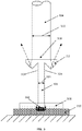
- each fiber optic bundle leg 304 directs laser light from a laser light source (such as laser light source 122) through waveguide 306 through transmissive plastic part to be welded 308, where it is absorbed by absorptive plastic part to be welded 310 to form weld spot 302 at a point along the weld path where the plastic parts are welded together.
- a weld spot 302 is formed at each point along the weld path where laser light from an individual fiber optic bundle leg 304 impinges the weld path after traveling through the waveguide.
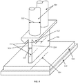
- the weld spots 302 collectively define a weld line 314 of the weld (shown in phantom in FIG. 4 ).
- the term "width" or "weld width” when referring to a weld means a width of the weld along the weld line at any applicable point, that is, the width of the weld across the weld line at any applicable point.
- the term "fiber optic bundle leg” means a plurality of laser delivery optical fibers and can include a leg (such as a leg of a laser delivery bundle) comprised of a plurality of laser delivery optical fibers and/or a laser delivery bundle comprised of a plurality of legs and/or comprised of a plurality of laser delivery optical fibers.
- a leg such as a leg of a laser delivery bundle
- a laser delivery bundle comprised of a plurality of legs and/or comprised of a plurality of laser delivery optical fibers.
- waveguide 306 associated with each fiber optical bundle leg 304 which is where laser light from that fiber optical bundle leg 304 travels through the waveguide 306.
- waveguide 306 and associated laser delivery optical fiber 304 this refers to the portion 316 of waveguide 306 where the laser light from that laser delivery optical fiber 304 travels through the waveguide 306. It should also be understood that the portions 316 of waveguide 306 could alternatively be provided by individual waveguides.
- each weld spot 302 has a width that is significantly smaller than a width of the fiber optic bundle leg 304 that provided the laser light that formed that weld spot 302.
- This significantly narrowed weld spot 302 is accomplished by the portion 316 of waveguide 306 having a width 320 that is significantly narrower than a width 322 of the associated fiber optic bundle leg 304, such as a diameter of fiber optic bundle leg 304 when fiber optic bundle leg 304 has a circular cross-section such as in the example of Figs. 3 and 4 .
- Reflective bounce planes 312 associated with each fiber optic bundle leg 304 reflect the first portion of laser light and the second portion of laser light travels through the associated portion 316 of waveguide 306 to a point on the weld path along which parts 308, 310 are welded together and forms weld spot 302.
- at least one reflective bounce plane is disposed at an outlet 318 of each fiber optic bundle leg 304.
- each portion 316 of waveguide 306 there are reflective bounce planes 312 disposed at opposite sides 324 of each portion 316 of waveguide 306 so that these reflective bounce planes 312 reflect laser light on opposite sides of the weld line 314.
- the reflective bounce planes 312 are part of waveguide 306. Opposite sides 324 are opposed to each other across width 320 of portion 316.
- Reflective bounce planes 312 preferably comprise material that reflect rather than absorb laser light used in STTIr applications. Accordingly, reflective bounce planes include laser mirrors, polished metal surfaces and total internal reflection surfaces. Reflective bounce planes 312 redirect laser light away from parts 308, 312 to be welded to prevent unwanted welding of same and away from the laser light source 122 or fiber optic bundle leg 304 to avoid damaging the laser system. Typically, reflective bounce planes 312 are placed at the end ( e.g ., outlet 318) of each fiber optic bundle leg 304 and an inlet of each portion 316 of waveguide 306.
- each portion 316 of waveguide 306 has a width that is narrower than a width of the associated fiber optic bundle leg 304.
- each portion 316 of waveguide 306 must be long enough to homogenize the laser light travelling through portion 316 of waveguide 306, thereby allowing for a uniform weld.
- each portion 316 of waveguide 306 has a uniform width along its length.
- FIG. 4 an alternate view of the embodiment disclosed at FIG. 3 is shown.
- multiple fiber optic bundle legs 304 simultaneously transmit laser light from a laser light source through associated portions 316 of waveguide 306 through to parts 308, 310 to be welded, which results in a weld area generally defined by an exit side of waveguide 306, wherein the exit side is defined by the side most nearly facing parts 308, 312 to be welded.
- Each portion 316 of waveguide 306 must extend sufficiently in a vertical direction to homogenize laser light passing through to parts 308, 310 to be welded.
- a waveguide can be fashioned to provide a weld length of any desirable or predetermined shape. Therefore, while waveguide 306 is shown in FIG. 4 as appearing straight along its length, it should be understood that waveguide 306 can be curvilinear. Similarly, while waveguide 306 is shown in FIG. 4 as appearing planar, it should be understood that waveguide 306 can have any orientation, three dimensionality, or other twists along a planar reference. It is further envisioned that waveguide 306 need not have a fixed width throughout the entire waveguide with one or more portions 316 of waveguide 306 having different widths than one or more of the other portions 316.
- the resulting weld line need not have a consistent width, and that the width at a given point along the weld line may be dependent on the width of the portion 316 of waveguide 306 adjacent that given point along the weld line, any resultant angular spread, and the width of fiber optic leg bundle 304 not redirected by reflective bounce plane 312 at that particular point.
- the waveguide output shape can be fashioned as warranted by weld parameters or preferences, such as a triangle, dot, or blob.
- the waveguide can be positive or negative or any combination of the two.
- a positive waveguide uses a solid medium that transmits the laser light and guides the light by total internal reflection.
- a negative waveguide transmits through a vacuum, gas, liquid or solid but relies on reflective walls to guide the laser light.
- the technology described above is suitable for use as a part of an STTIr laser welding system, such as the STTIr laser welding system 100 shown in FIG. 1 .
- fiber optic bundle legs 304 would replace the legs of laser delivery bundle 10 and waveguide 306, along with the reflective bounce planes 312, would replace waveguide 30.
- Such a modified STTIr system would provide significantly narrower weld widths than possible with a conventional STTIr system using similarly sized fiber optic bundle legs. It is further contemplated that in such a system that laser light applied to the parts to be welded would form a weld length having a weld width significantly narrower than a weld width possible with a conventional STTIr system.
- the resulting weld line could result in many forms, including being linear, curvilinear, continuous, discontinuous, having twists, and exhibiting a three-dimensional weld length.
- a weld line could be produced with a waveguide that is shaped to produce a desired shape, such as a triangle, dot, or blob.
- the width of the weld line could vary along the path of the weld line, to the extent the width of the waveguide and/or corresponding reflective bounce planes change along the waveguide.
Landscapes
- Physics & Mathematics (AREA)
- Engineering & Computer Science (AREA)
- Optics & Photonics (AREA)
- Mechanical Engineering (AREA)
- Health & Medical Sciences (AREA)
- Toxicology (AREA)
- Electromagnetism (AREA)
- Plasma & Fusion (AREA)
- Robotics (AREA)
- Laser Beam Processing (AREA)
- Lining Or Joining Of Plastics Or The Like (AREA)
Claims (14)
- Verfahren zum Zusammenschweißen mehrerer Werkstücke entlang eines Schweißpfades in einem Simultanlaserschweißsystem; wobei das Simultanlaserschweißsystem mehrere Laserabgabebündel aufweist, wobei jedes Laserabgabebündel mindestens einen Glasfaserbündelschenkel (304) und einen Wellenleiter (306) umfasst, die zwischen den Glasfaserbündelschenkeln (304) und dem mehreren Werkstücken angeordnet sind, wobei das Verfahren Folgendes umfasst:Leiten von Laserlicht von mindestens einer Laserlichtquelle (122) durch jeden Glasfaserbündelschenkel (304) zu einem Abschnitt (316) des Wellenleiters (306), der diesem Glasfaserbündelschenkel (304) zugeordnet ist;Bereitstellen jedes Abschnitts (316) des Wellenleiters (306) mit einer Breite, die schmaler ist als eine Breite des Glasfaserbündelschenkels (304), dem dieser Abschnitt des Wellenleiters (306) zugeordnet ist; undBereitstellen einer reflektierenden Rückprallebene (312) für jeden Glasfaserbündelschenkel (304) an einem Auslass des Glasfaserbündelschenkels (304) und Reflektieren mit der reflektierenden Rückprallebene (312) für jeden Glasfaserbündelschenkel (304) eines ersten Abschnitts des Laserlichts von diesem Glasfaserbündelschenkel (304) und wobei ein zweiter Abschnitt des Laserlichts von diesem Glasfaserbündelschenkel (304) durch den Abschnitt (316) des Wellenleiters (306), der diesem Glasfaserbündelschenkel (304) zugeordnet ist, zu dem Schweißpfad wandert, um eine Schweißnaht bereitzustellen, wo der zweite Abschnitt des Laserlichts mit einer Breite auf den Schweißpfad trifft, die schmaler ist als die Breite dieses Glasfaserbündelschenkels (304).
- Verfahren nach Anspruch 1, wobei das Wandern des zweiten Abschnitts des Laserlichts von jedem Glasfaserbündelschenkel (304) durch seinen zugeordneten Abschnitt (316) des Wellenleiters (306) das Homogenisieren des Laserlichts, das sich durch den Wellenleiter bewegt, mit dem zugehörigen Abschnitt des Wellenleiters umfasst.
- Verfahren nach Anspruch 1, das das Positionieren der Glasfaserbündelschenkel (304) und des Wellenleiters (306) umfasst, um die mehreren Werkstücke entlang des Schweißpfades zusammenzuschweißen, wobei die Schweißnaht entlang einer Schweißlinie durchgehend ist.
- Verfahren nach Anspruch 1, das das Positionieren der Glasfaserbündelschenkel (304) und des Wellenleiters (306) umfasst, um die mehreren Werkstücke entlang des Schweißpfades zusammenzuschweißen, wobei die Schweißnaht eine lineare Schweißlinie aufweist.
- Verfahren nach Anspruch 1, das das Positionieren der Glasfaserbündelschenkel (304) und des Wellenleiters (306) umfasst, um die mehreren Werkstücke entlang des Schweißpfades zusammenzuschweißen, wobei die Schweißnaht eine kurvenförmige Schweißlinie aufweist.
- Verfahren nach Anspruch 1, das das Positionieren der Glasfaserbündelschenkel (304) und des Wellenleiters (306) umfasst, um die mehreren Werkstücke entlang des Schweißpfades zusammenzuschweißen, wobei die Schweißnaht entlang einer Schweißlinie unterbrochen ist.
- Verfahren nach Anspruch 1, wobei das Reflektieren des ersten Abschnitts des Laserlichts durch jede reflektierende Rückprallebene (312) das Reflektieren des ersten Abschnitts des Laserlichts von der Laserlichtquelle (122) umfasst.
- Simultan-Laserschweißsystem zum Zusammenschweißen mehrerer Werkstücke entlang eines Schweißpfades, wobei das Simultan-Laserschweißsystem Folgendes umfasst:eine Laserbank mit einer Laserlichtquelle (122);mehrere Laserabgabebündel, wobei jedes Laserabgabebündel mindestens einen Glasfaserbündelschenkel (304) umfasst;einen Wellenleiter (306) mit einem Abschnitt (316), der jedem Glasfaserbündelschenkel (304) zugeordnet ist wobei jeder Abschnitt (316) des Wellenleiters (306) eine Breite aufweist, die schmaler ist als eine Breite des Glasfaserbündelschenkels (304), dem der Abschnitt (316) des Wellenleiters (306) zugeordnet ist, wobei der Wellenleiter (306) zwischen den mehreren Werkstücken und den Glasfaserbündelschenkeln (304) angeordnet ist;wobei sich die Glasfaserbündelschenkel (304) zwischen der Laserbank und dem Wellenleiter (306) mit Laserlicht von der Laserlichtquelle (122) der Laserbank erstrecken, das durch die Glasfaserbündelschenkel (304) zum Wellenleiter (306) gerichtet ist;eine reflektierende Rückprallebene (312), die jedem Glasfaserbündelschenkel (304) zugeordnet und an einem Auslass dieses Glasfaserbündelschenkels (304) angeordnet ist, wobei jede reflektierende Rückprallebene (312) dafür konfiguriert ist, einen ersten Abschnitt des Laserlichts von dem Glasfaserbündelschenkel (304) zu reflektieren, dem diese reflektierende Rückprallebene (312) zugeordnet ist;wobei jeder Abschnitt des Wellenleiters (306) dafür konfiguriert ist, einen Pfad bereitzustellen, durch den sich Laserlicht von dem diesem Abschnitt zugeordneten Glasfaserbündelschenkel (304) bewegt, und um dieses Laserlicht auf den Schweißpfad zu lenken, wobei eine Breite einer Schweißnaht, bei der ein zweiter Abschnitt des Laserlichts auf den Schweißpfad auftrifft, schmaler ist als die Breite dieses Glasfaserbündelschenkel s.
- Simultanlaserschweißsystem nach Anspruch 8, wobei jeder Abschnitt (316) des Wellenleiters (306) das durch diesen Abschnitt wandernde Laserlicht homogenisiert.
- Simultanlaserschweißsystem nach Anspruch 8, wobei die Schweißnaht entlang des Schweißpfades eine durchgehende Schweißlinie ist.
- Simultanlaserschweißsystem nach Anspruch 8, wobei die Schweißnaht entlang des Schweißpfades eine lineare Schweißlinie ist.
- Simultanlaserschweißsystem nach Anspruch 8, wobei die Schweißnaht entlang des Schweißpfades eine kurvenförmige Schweißnaht ist.
- Simultanlaserschweißsystem nach Anspruch 8, wobei die Schweißnaht entlang des Schweißpfades eine unterbrochene Schweißlinie ist.
- Simultanlaserschweißsystem nach Anspruch 8, wobei jede reflektierende Rückprallebene (312) das Laserlicht von der Laserlichtquelle (122) weg reflektiert.
Priority Applications (1)
| Application Number | Priority Date | Filing Date | Title |
|---|---|---|---|
| PL19703915T PL3737553T3 (pl) | 2018-01-22 | 2019-01-18 | Falowód do wąskiego jednoczesnego zgrzewania laserowego tworzyw sztucznych |
Applications Claiming Priority (2)
| Application Number | Priority Date | Filing Date | Title |
|---|---|---|---|
| US201862620168P | 2018-01-22 | 2018-01-22 | |
| PCT/US2019/014303 WO2019144011A1 (en) | 2018-01-22 | 2019-01-18 | Waveguide for narrow simultaneous laser plastics welding |
Publications (2)
| Publication Number | Publication Date |
|---|---|
| EP3737553A1 EP3737553A1 (de) | 2020-11-18 |
| EP3737553B1 true EP3737553B1 (de) | 2021-06-30 |
Family
ID=65324661
Family Applications (1)
| Application Number | Title | Priority Date | Filing Date |
|---|---|---|---|
| EP19703915.9A Active EP3737553B1 (de) | 2018-01-22 | 2019-01-18 | Wellenleiter für schmales simultanes laserschweissen von kunststoffen |
Country Status (8)
| Country | Link |
|---|---|
| US (1) | US10814560B2 (de) |
| EP (1) | EP3737553B1 (de) |
| JP (1) | JP7177841B2 (de) |
| KR (1) | KR102859865B1 (de) |
| CN (1) | CN111757804B (de) |
| ES (1) | ES2882675T3 (de) |
| PL (1) | PL3737553T3 (de) |
| WO (1) | WO2019144011A1 (de) |
Families Citing this family (1)
| Publication number | Priority date | Publication date | Assignee | Title |
|---|---|---|---|---|
| KR102679222B1 (ko) * | 2024-01-15 | 2024-06-27 | 케이투레이저시스템 (주) | 플라스틱 레이저 융착 시스템 |
Family Cites Families (14)
| Publication number | Priority date | Publication date | Assignee | Title |
|---|---|---|---|---|
| US4143660A (en) * | 1977-05-09 | 1979-03-13 | Malyshev Boris N | Method of surgery making use of laser emission and an apparatus for accomplishing same |
| DE10196087B3 (de) * | 2000-04-11 | 2019-01-10 | Branson Ultrasonics Corp. | Lichtleiter zum Laserschweißen |
| US6329629B1 (en) | 2000-04-28 | 2001-12-11 | Branson Ultrasonics Corporation | Distance mode control for laser welding |
| US6713713B1 (en) | 2002-12-18 | 2004-03-30 | Branson Ultrasonics Corporation | Lens to adapt laser intensity for uniform welding |
| US20050121424A1 (en) * | 2003-12-05 | 2005-06-09 | Scott Caldwell | Optical horned lightpipe or lightguide |
| US7085296B2 (en) | 2003-12-05 | 2006-08-01 | Branson Ultrasonics Corporation | Dual parameter laser optical feedback |
| US20070000887A1 (en) * | 2005-06-29 | 2007-01-04 | Scott Caldwell | Method for scan welding or marking through a waveguide and waveguide therefor |
| US20070047932A1 (en) * | 2005-08-31 | 2007-03-01 | Branson Ultrasonics Corporation | Waveguide for plastics welding using an incoherent infrared light source |
| US7343218B2 (en) | 2006-05-09 | 2008-03-11 | Branson Ultrasonics Corporation | Automatic part feedback compensation for laser plastics welding |
| JP2008307839A (ja) * | 2007-06-18 | 2008-12-25 | Ito Yoshihiko | レーザー溶着方法 |
| DE102009053261A1 (de) * | 2009-11-11 | 2011-05-12 | Jenoptik Automatisierungstechnik Gmbh | Vorrichtung zum Punktschweißen mit Laserstrahl |
| US20130312903A1 (en) * | 2012-05-22 | 2013-11-28 | Shenzhen China Star Optoelectronics Technology Co., Ltd. | Curing Device for Sealant of LCD Panel and Method for Curing the Sealant |
| EP2957418B1 (de) | 2014-06-19 | 2020-01-01 | Marelli Automotive Lighting Italy S.p.A. | Vorrichtung zur herstellung eines kraftfahrzeugscheinwerfers und verfahren zum gleichzeitigen laserschweissen eines kraftfahrzeugscheinwerfers |
| JP2016083799A (ja) * | 2014-10-24 | 2016-05-19 | 株式会社小糸製作所 | 溶着方法及び溶着装置 |
-
2019
- 2019-01-18 PL PL19703915T patent/PL3737553T3/pl unknown
- 2019-01-18 CN CN201980014736.5A patent/CN111757804B/zh active Active
- 2019-01-18 EP EP19703915.9A patent/EP3737553B1/de active Active
- 2019-01-18 ES ES19703915T patent/ES2882675T3/es active Active
- 2019-01-18 JP JP2020540497A patent/JP7177841B2/ja active Active
- 2019-01-18 WO PCT/US2019/014303 patent/WO2019144011A1/en not_active Ceased
- 2019-01-18 US US16/251,295 patent/US10814560B2/en active Active
- 2019-01-18 KR KR1020207023760A patent/KR102859865B1/ko active Active
Non-Patent Citations (1)
| Title |
|---|
| None * |
Also Published As
| Publication number | Publication date |
|---|---|
| CN111757804A (zh) | 2020-10-09 |
| US20190224921A1 (en) | 2019-07-25 |
| WO2019144011A1 (en) | 2019-07-25 |
| CN111757804B (zh) | 2022-09-23 |
| JP2021511232A (ja) | 2021-05-06 |
| KR102859865B1 (ko) | 2025-09-16 |
| US10814560B2 (en) | 2020-10-27 |
| EP3737553A1 (de) | 2020-11-18 |
| JP7177841B2 (ja) | 2022-11-24 |
| PL3737553T3 (pl) | 2021-12-20 |
| ES2882675T3 (es) | 2021-12-02 |
| KR20200106962A (ko) | 2020-09-15 |
Similar Documents
| Publication | Publication Date | Title |
|---|---|---|
| US20190262942A1 (en) | Methods and laser welding devices for deep welding a workpiece | |
| US6528755B2 (en) | Light guide for laser welding | |
| US8343299B2 (en) | Infrared plastic welding with recirculation of unabsorbed infrared laser light to increase absorption of infrared laser light | |
| US20140216648A1 (en) | Method and apparatus for laser welding of two joining members of plastic material | |
| KR102034068B1 (ko) | 레이저 용접 시스템 및 레이저 빔에 의한 용접 방법 | |
| US7723640B2 (en) | Optical horned lightpipe or lightguide | |
| WO2007007766A1 (ja) | 光照射装置および溶着方法 | |
| EP4035820A1 (de) | Laserbearbeitungskopf mit blende zur vergrösserung des abtastfeldes des laserstrahls | |
| US10814560B2 (en) | Waveguide for narrow simultaneous laser plastics welding | |
| JPH01162587A (ja) | レーザ溶接方法 | |
| CN116323075A (zh) | 激光焊接处理中的束整形系统 | |
| US20070235431A1 (en) | Laser hardening method | |
| JP7136601B2 (ja) | 導光装置及びレーザ加工装置 | |
| US20070000887A1 (en) | Method for scan welding or marking through a waveguide and waveguide therefor | |
| CN111864526B (zh) | 激光束乘积参数调整 | |
| WO2018217922A1 (en) | Simultaneous laser welding with control by profiling | |
| US11034095B2 (en) | Waveguide segment for plastic welding, arrangement for plastic welding, a welding method as well as a manufacturing method of a waveguide segment | |
| JP2017217658A (ja) | レーザ加工装置、レーザ加工方法、光学系、及び肉盛り加工品 | |
| JP2017135146A (ja) | レーザヘッド、及び、レーザ装置 | |
| WO2018217930A1 (en) | Infrared through transmissive laser welding using complementary optical part | |
| JPH0255305A (ja) | 側射型中空導波路 |
Legal Events
| Date | Code | Title | Description |
|---|---|---|---|
| STAA | Information on the status of an ep patent application or granted ep patent |
Free format text: STATUS: UNKNOWN |
|
| STAA | Information on the status of an ep patent application or granted ep patent |
Free format text: STATUS: THE INTERNATIONAL PUBLICATION HAS BEEN MADE |
|
| PUAI | Public reference made under article 153(3) epc to a published international application that has entered the european phase |
Free format text: ORIGINAL CODE: 0009012 |
|
| STAA | Information on the status of an ep patent application or granted ep patent |
Free format text: STATUS: REQUEST FOR EXAMINATION WAS MADE |
|
| 17P | Request for examination filed |
Effective date: 20200810 |
|
| AK | Designated contracting states |
Kind code of ref document: A1 Designated state(s): AL AT BE BG CH CY CZ DE DK EE ES FI FR GB GR HR HU IE IS IT LI LT LU LV MC MK MT NL NO PL PT RO RS SE SI SK SM TR |
|
| AX | Request for extension of the european patent |
Extension state: BA ME |
|
| GRAP | Despatch of communication of intention to grant a patent |
Free format text: ORIGINAL CODE: EPIDOSNIGR1 |
|
| STAA | Information on the status of an ep patent application or granted ep patent |
Free format text: STATUS: GRANT OF PATENT IS INTENDED |
|
| DAV | Request for validation of the european patent (deleted) | ||
| DAX | Request for extension of the european patent (deleted) | ||
| INTG | Intention to grant announced |
Effective date: 20210114 |
|
| GRAS | Grant fee paid |
Free format text: ORIGINAL CODE: EPIDOSNIGR3 |
|
| GRAA | (expected) grant |
Free format text: ORIGINAL CODE: 0009210 |
|
| STAA | Information on the status of an ep patent application or granted ep patent |
Free format text: STATUS: THE PATENT HAS BEEN GRANTED |
|
| AK | Designated contracting states |
Kind code of ref document: B1 Designated state(s): AL AT BE BG CH CY CZ DE DK EE ES FI FR GB GR HR HU IE IS IT LI LT LU LV MC MK MT NL NO PL PT RO RS SE SI SK SM TR |
|
| REG | Reference to a national code |
Ref country code: CH Ref legal event code: EP |
|
| REG | Reference to a national code |
Ref country code: AT Ref legal event code: REF Ref document number: 1405962 Country of ref document: AT Kind code of ref document: T Effective date: 20210715 |
|
| REG | Reference to a national code |
Ref country code: DE Ref legal event code: R096 Ref document number: 602019005781 Country of ref document: DE |
|
| REG | Reference to a national code |
Ref country code: IE Ref legal event code: FG4D |
|
| REG | Reference to a national code |
Ref country code: LT Ref legal event code: MG9D |
|
| REG | Reference to a national code |
Ref country code: SK Ref legal event code: T3 Ref document number: E 37974 Country of ref document: SK |
|
| PG25 | Lapsed in a contracting state [announced via postgrant information from national office to epo] |
Ref country code: BG Free format text: LAPSE BECAUSE OF FAILURE TO SUBMIT A TRANSLATION OF THE DESCRIPTION OR TO PAY THE FEE WITHIN THE PRESCRIBED TIME-LIMIT Effective date: 20210930 Ref country code: FI Free format text: LAPSE BECAUSE OF FAILURE TO SUBMIT A TRANSLATION OF THE DESCRIPTION OR TO PAY THE FEE WITHIN THE PRESCRIBED TIME-LIMIT Effective date: 20210630 Ref country code: HR Free format text: LAPSE BECAUSE OF FAILURE TO SUBMIT A TRANSLATION OF THE DESCRIPTION OR TO PAY THE FEE WITHIN THE PRESCRIBED TIME-LIMIT Effective date: 20210630 |
|
| REG | Reference to a national code |
Ref country code: NL Ref legal event code: MP Effective date: 20210630 |
|
| REG | Reference to a national code |
Ref country code: AT Ref legal event code: MK05 Ref document number: 1405962 Country of ref document: AT Kind code of ref document: T Effective date: 20210630 |
|
| PG25 | Lapsed in a contracting state [announced via postgrant information from national office to epo] |
Ref country code: GR Free format text: LAPSE BECAUSE OF FAILURE TO SUBMIT A TRANSLATION OF THE DESCRIPTION OR TO PAY THE FEE WITHIN THE PRESCRIBED TIME-LIMIT Effective date: 20211001 Ref country code: LV Free format text: LAPSE BECAUSE OF FAILURE TO SUBMIT A TRANSLATION OF THE DESCRIPTION OR TO PAY THE FEE WITHIN THE PRESCRIBED TIME-LIMIT Effective date: 20210630 Ref country code: NO Free format text: LAPSE BECAUSE OF FAILURE TO SUBMIT A TRANSLATION OF THE DESCRIPTION OR TO PAY THE FEE WITHIN THE PRESCRIBED TIME-LIMIT Effective date: 20210930 Ref country code: RS Free format text: LAPSE BECAUSE OF FAILURE TO SUBMIT A TRANSLATION OF THE DESCRIPTION OR TO PAY THE FEE WITHIN THE PRESCRIBED TIME-LIMIT Effective date: 20210630 Ref country code: SE Free format text: LAPSE BECAUSE OF FAILURE TO SUBMIT A TRANSLATION OF THE DESCRIPTION OR TO PAY THE FEE WITHIN THE PRESCRIBED TIME-LIMIT Effective date: 20210630 |
|
| REG | Reference to a national code |
Ref country code: ES Ref legal event code: FG2A Ref document number: 2882675 Country of ref document: ES Kind code of ref document: T3 Effective date: 20211202 |
|
| PG25 | Lapsed in a contracting state [announced via postgrant information from national office to epo] |
Ref country code: SM Free format text: LAPSE BECAUSE OF FAILURE TO SUBMIT A TRANSLATION OF THE DESCRIPTION OR TO PAY THE FEE WITHIN THE PRESCRIBED TIME-LIMIT Effective date: 20210630 Ref country code: RO Free format text: LAPSE BECAUSE OF FAILURE TO SUBMIT A TRANSLATION OF THE DESCRIPTION OR TO PAY THE FEE WITHIN THE PRESCRIBED TIME-LIMIT Effective date: 20210630 Ref country code: PT Free format text: LAPSE BECAUSE OF FAILURE TO SUBMIT A TRANSLATION OF THE DESCRIPTION OR TO PAY THE FEE WITHIN THE PRESCRIBED TIME-LIMIT Effective date: 20211102 Ref country code: NL Free format text: LAPSE BECAUSE OF FAILURE TO SUBMIT A TRANSLATION OF THE DESCRIPTION OR TO PAY THE FEE WITHIN THE PRESCRIBED TIME-LIMIT Effective date: 20210630 Ref country code: CZ Free format text: LAPSE BECAUSE OF FAILURE TO SUBMIT A TRANSLATION OF THE DESCRIPTION OR TO PAY THE FEE WITHIN THE PRESCRIBED TIME-LIMIT Effective date: 20210630 Ref country code: AT Free format text: LAPSE BECAUSE OF FAILURE TO SUBMIT A TRANSLATION OF THE DESCRIPTION OR TO PAY THE FEE WITHIN THE PRESCRIBED TIME-LIMIT Effective date: 20210630 Ref country code: EE Free format text: LAPSE BECAUSE OF FAILURE TO SUBMIT A TRANSLATION OF THE DESCRIPTION OR TO PAY THE FEE WITHIN THE PRESCRIBED TIME-LIMIT Effective date: 20210630 |
|
| REG | Reference to a national code |
Ref country code: DE Ref legal event code: R097 Ref document number: 602019005781 Country of ref document: DE |
|
| PG25 | Lapsed in a contracting state [announced via postgrant information from national office to epo] |
Ref country code: DK Free format text: LAPSE BECAUSE OF FAILURE TO SUBMIT A TRANSLATION OF THE DESCRIPTION OR TO PAY THE FEE WITHIN THE PRESCRIBED TIME-LIMIT Effective date: 20210630 |
|
| PLBE | No opposition filed within time limit |
Free format text: ORIGINAL CODE: 0009261 |
|
| STAA | Information on the status of an ep patent application or granted ep patent |
Free format text: STATUS: NO OPPOSITION FILED WITHIN TIME LIMIT |
|
| PG25 | Lapsed in a contracting state [announced via postgrant information from national office to epo] |
Ref country code: AL Free format text: LAPSE BECAUSE OF FAILURE TO SUBMIT A TRANSLATION OF THE DESCRIPTION OR TO PAY THE FEE WITHIN THE PRESCRIBED TIME-LIMIT Effective date: 20210630 |
|
| 26N | No opposition filed |
Effective date: 20220331 |
|
| PG25 | Lapsed in a contracting state [announced via postgrant information from national office to epo] |
Ref country code: MC Free format text: LAPSE BECAUSE OF FAILURE TO SUBMIT A TRANSLATION OF THE DESCRIPTION OR TO PAY THE FEE WITHIN THE PRESCRIBED TIME-LIMIT Effective date: 20210630 |
|
| REG | Reference to a national code |
Ref country code: BE Ref legal event code: MM Effective date: 20220131 |
|
| PG25 | Lapsed in a contracting state [announced via postgrant information from national office to epo] |
Ref country code: LU Free format text: LAPSE BECAUSE OF NON-PAYMENT OF DUE FEES Effective date: 20220118 |
|
| PG25 | Lapsed in a contracting state [announced via postgrant information from national office to epo] |
Ref country code: BE Free format text: LAPSE BECAUSE OF NON-PAYMENT OF DUE FEES Effective date: 20220131 |
|
| PG25 | Lapsed in a contracting state [announced via postgrant information from national office to epo] |
Ref country code: LT Free format text: LAPSE BECAUSE OF FAILURE TO SUBMIT A TRANSLATION OF THE DESCRIPTION OR TO PAY THE FEE WITHIN THE PRESCRIBED TIME-LIMIT Effective date: 20210630 |
|
| P01 | Opt-out of the competence of the unified patent court (upc) registered |
Effective date: 20230519 |
|
| PG25 | Lapsed in a contracting state [announced via postgrant information from national office to epo] |
Ref country code: MK Free format text: LAPSE BECAUSE OF FAILURE TO SUBMIT A TRANSLATION OF THE DESCRIPTION OR TO PAY THE FEE WITHIN THE PRESCRIBED TIME-LIMIT Effective date: 20210630 Ref country code: CY Free format text: LAPSE BECAUSE OF FAILURE TO SUBMIT A TRANSLATION OF THE DESCRIPTION OR TO PAY THE FEE WITHIN THE PRESCRIBED TIME-LIMIT Effective date: 20210630 |
|
| PG25 | Lapsed in a contracting state [announced via postgrant information from national office to epo] |
Ref country code: HU Free format text: LAPSE BECAUSE OF FAILURE TO SUBMIT A TRANSLATION OF THE DESCRIPTION OR TO PAY THE FEE WITHIN THE PRESCRIBED TIME-LIMIT; INVALID AB INITIO Effective date: 20190118 |
|
| PG25 | Lapsed in a contracting state [announced via postgrant information from national office to epo] |
Ref country code: MT Free format text: LAPSE BECAUSE OF FAILURE TO SUBMIT A TRANSLATION OF THE DESCRIPTION OR TO PAY THE FEE WITHIN THE PRESCRIBED TIME-LIMIT Effective date: 20210630 |
|
| PG25 | Lapsed in a contracting state [announced via postgrant information from national office to epo] |
Ref country code: TR Free format text: LAPSE BECAUSE OF FAILURE TO SUBMIT A TRANSLATION OF THE DESCRIPTION OR TO PAY THE FEE WITHIN THE PRESCRIBED TIME-LIMIT Effective date: 20210630 |
|
| PGFP | Annual fee paid to national office [announced via postgrant information from national office to epo] |
Ref country code: GB Payment date: 20251219 Year of fee payment: 8 |
|
| PGFP | Annual fee paid to national office [announced via postgrant information from national office to epo] |
Ref country code: FR Payment date: 20251217 Year of fee payment: 8 |
|
| PGFP | Annual fee paid to national office [announced via postgrant information from national office to epo] |
Ref country code: IE Payment date: 20251218 Year of fee payment: 8 |
|
| PGFP | Annual fee paid to national office [announced via postgrant information from national office to epo] |
Ref country code: PL Payment date: 20251229 Year of fee payment: 8 |
|
| PGFP | Annual fee paid to national office [announced via postgrant information from national office to epo] |
Ref country code: SK Payment date: 20251223 Year of fee payment: 8 |
|
| REG | Reference to a national code |
Ref country code: CH Ref legal event code: U11 Free format text: ST27 STATUS EVENT CODE: U-0-0-U10-U11 (AS PROVIDED BY THE NATIONAL OFFICE) Effective date: 20260201 |
|
| PGFP | Annual fee paid to national office [announced via postgrant information from national office to epo] |
Ref country code: ES Payment date: 20260202 Year of fee payment: 8 |
|
| PGFP | Annual fee paid to national office [announced via postgrant information from national office to epo] |
Ref country code: DE Payment date: 20251217 Year of fee payment: 8 |
|
| PGFP | Annual fee paid to national office [announced via postgrant information from national office to epo] |
Ref country code: IT Payment date: 20260107 Year of fee payment: 8 |
|
| PGFP | Annual fee paid to national office [announced via postgrant information from national office to epo] |
Ref country code: CH Payment date: 20260201 Year of fee payment: 8 |