EP3737547B1 - Verfahren zur kontinuierlichen herstellung einer prägefolienbahn und zugehörige anlage - Google Patents
Verfahren zur kontinuierlichen herstellung einer prägefolienbahn und zugehörige anlage Download PDFInfo
- Publication number
- EP3737547B1 EP3737547B1 EP19703170.1A EP19703170A EP3737547B1 EP 3737547 B1 EP3737547 B1 EP 3737547B1 EP 19703170 A EP19703170 A EP 19703170A EP 3737547 B1 EP3737547 B1 EP 3737547B1
- Authority
- EP
- European Patent Office
- Prior art keywords
- compression
- embossing
- cylinder
- primary
- pressure
- Prior art date
- Legal status (The legal status is an assumption and is not a legal conclusion. Google has not performed a legal analysis and makes no representation as to the accuracy of the status listed.)
- Active
Links
- 238000000034 method Methods 0.000 title claims description 59
- 238000009434 installation Methods 0.000 title description 39
- 230000006835 compression Effects 0.000 claims description 201
- 238000007906 compression Methods 0.000 claims description 201
- 238000004049 embossing Methods 0.000 claims description 165
- 239000000463 material Substances 0.000 claims description 34
- 238000004519 manufacturing process Methods 0.000 claims description 30
- 238000010438 heat treatment Methods 0.000 claims description 22
- 239000004753 textile Substances 0.000 claims description 11
- 238000011144 upstream manufacturing Methods 0.000 claims description 8
- 230000001105 regulatory effect Effects 0.000 claims description 7
- 239000006260 foam Substances 0.000 claims description 5
- 238000012544 monitoring process Methods 0.000 claims description 3
- 239000010410 layer Substances 0.000 description 52
- 238000003825 pressing Methods 0.000 description 38
- 230000000694 effects Effects 0.000 description 16
- 238000003490 calendering Methods 0.000 description 7
- 229920001971 elastomer Polymers 0.000 description 5
- 239000000806 elastomer Substances 0.000 description 5
- 239000000203 mixture Substances 0.000 description 5
- 230000005540 biological transmission Effects 0.000 description 4
- 230000000295 complement effect Effects 0.000 description 4
- 230000001276 controlling effect Effects 0.000 description 4
- 229910000831 Steel Inorganic materials 0.000 description 3
- 238000013461 design Methods 0.000 description 3
- 239000004744 fabric Substances 0.000 description 3
- 239000000835 fiber Substances 0.000 description 3
- 238000002844 melting Methods 0.000 description 3
- 230000008018 melting Effects 0.000 description 3
- 239000002184 metal Substances 0.000 description 3
- 239000010959 steel Substances 0.000 description 3
- 238000009941 weaving Methods 0.000 description 3
- 229910000851 Alloy steel Inorganic materials 0.000 description 2
- 230000015556 catabolic process Effects 0.000 description 2
- 239000011248 coating agent Substances 0.000 description 2
- 238000000576 coating method Methods 0.000 description 2
- 230000007547 defect Effects 0.000 description 2
- 238000006731 degradation reaction Methods 0.000 description 2
- 230000006866 deterioration Effects 0.000 description 2
- 229910052500 inorganic mineral Inorganic materials 0.000 description 2
- 238000012423 maintenance Methods 0.000 description 2
- 239000011707 mineral Substances 0.000 description 2
- 239000004745 nonwoven fabric Substances 0.000 description 2
- 239000007787 solid Substances 0.000 description 2
- 238000004381 surface treatment Methods 0.000 description 2
- OKTJSMMVPCPJKN-UHFFFAOYSA-N Carbon Chemical compound [C] OKTJSMMVPCPJKN-UHFFFAOYSA-N 0.000 description 1
- 229920000742 Cotton Polymers 0.000 description 1
- 239000004952 Polyamide Substances 0.000 description 1
- 239000004698 Polyethylene Substances 0.000 description 1
- 229920005830 Polyurethane Foam Polymers 0.000 description 1
- 230000004075 alteration Effects 0.000 description 1
- 230000000181 anti-adherent effect Effects 0.000 description 1
- 239000004760 aramid Substances 0.000 description 1
- 229920003235 aromatic polyamide Polymers 0.000 description 1
- 230000009286 beneficial effect Effects 0.000 description 1
- 229910052799 carbon Inorganic materials 0.000 description 1
- 230000001413 cellular effect Effects 0.000 description 1
- 229920002678 cellulose Polymers 0.000 description 1
- 239000001913 cellulose Substances 0.000 description 1
- 239000002131 composite material Substances 0.000 description 1
- 238000007596 consolidation process Methods 0.000 description 1
- 238000001816 cooling Methods 0.000 description 1
- 230000008021 deposition Effects 0.000 description 1
- 238000001035 drying Methods 0.000 description 1
- 229920002457 flexible plastic Polymers 0.000 description 1
- 239000011521 glass Substances 0.000 description 1
- 239000012943 hotmelt Substances 0.000 description 1
- 238000009413 insulation Methods 0.000 description 1
- 238000009940 knitting Methods 0.000 description 1
- 238000005498 polishing Methods 0.000 description 1
- 229920002647 polyamide Polymers 0.000 description 1
- 229920000728 polyester Polymers 0.000 description 1
- -1 polyethylene Polymers 0.000 description 1
- 229920000573 polyethylene Polymers 0.000 description 1
- 229920002635 polyurethane Polymers 0.000 description 1
- 239000004814 polyurethane Substances 0.000 description 1
- 239000011496 polyurethane foam Substances 0.000 description 1
- 230000002035 prolonged effect Effects 0.000 description 1
- 239000010935 stainless steel Substances 0.000 description 1
- 229910001220 stainless steel Inorganic materials 0.000 description 1
- 239000002344 surface layer Substances 0.000 description 1
- 230000008961 swelling Effects 0.000 description 1
- 239000012209 synthetic fiber Substances 0.000 description 1
- 229920002994 synthetic fiber Polymers 0.000 description 1
- 238000012546 transfer Methods 0.000 description 1
- 230000000007 visual effect Effects 0.000 description 1
- XLYOFNOQVPJJNP-UHFFFAOYSA-N water Substances O XLYOFNOQVPJJNP-UHFFFAOYSA-N 0.000 description 1
- 238000004804 winding Methods 0.000 description 1
- 210000002268 wool Anatomy 0.000 description 1
Images
Classifications
-
- B—PERFORMING OPERATIONS; TRANSPORTING
- B29—WORKING OF PLASTICS; WORKING OF SUBSTANCES IN A PLASTIC STATE IN GENERAL
- B29C—SHAPING OR JOINING OF PLASTICS; SHAPING OF MATERIAL IN A PLASTIC STATE, NOT OTHERWISE PROVIDED FOR; AFTER-TREATMENT OF THE SHAPED PRODUCTS, e.g. REPAIRING
- B29C59/00—Surface shaping of articles, e.g. embossing; Apparatus therefor
- B29C59/02—Surface shaping of articles, e.g. embossing; Apparatus therefor by mechanical means, e.g. pressing
- B29C59/04—Surface shaping of articles, e.g. embossing; Apparatus therefor by mechanical means, e.g. pressing using rollers or endless belts
- B29C59/046—Surface shaping of articles, e.g. embossing; Apparatus therefor by mechanical means, e.g. pressing using rollers or endless belts for layered or coated substantially flat surfaces
-
- B—PERFORMING OPERATIONS; TRANSPORTING
- B29—WORKING OF PLASTICS; WORKING OF SUBSTANCES IN A PLASTIC STATE IN GENERAL
- B29C—SHAPING OR JOINING OF PLASTICS; SHAPING OF MATERIAL IN A PLASTIC STATE, NOT OTHERWISE PROVIDED FOR; AFTER-TREATMENT OF THE SHAPED PRODUCTS, e.g. REPAIRING
- B29C43/00—Compression moulding, i.e. applying external pressure to flow the moulding material; Apparatus therefor
- B29C43/22—Compression moulding, i.e. applying external pressure to flow the moulding material; Apparatus therefor of articles of indefinite length
- B29C43/24—Calendering
-
- B—PERFORMING OPERATIONS; TRANSPORTING
- B29—WORKING OF PLASTICS; WORKING OF SUBSTANCES IN A PLASTIC STATE IN GENERAL
- B29C—SHAPING OR JOINING OF PLASTICS; SHAPING OF MATERIAL IN A PLASTIC STATE, NOT OTHERWISE PROVIDED FOR; AFTER-TREATMENT OF THE SHAPED PRODUCTS, e.g. REPAIRING
- B29C43/00—Compression moulding, i.e. applying external pressure to flow the moulding material; Apparatus therefor
- B29C43/22—Compression moulding, i.e. applying external pressure to flow the moulding material; Apparatus therefor of articles of indefinite length
- B29C43/26—Compression moulding, i.e. applying external pressure to flow the moulding material; Apparatus therefor of articles of indefinite length in several steps
-
- B—PERFORMING OPERATIONS; TRANSPORTING
- B29—WORKING OF PLASTICS; WORKING OF SUBSTANCES IN A PLASTIC STATE IN GENERAL
- B29C—SHAPING OR JOINING OF PLASTICS; SHAPING OF MATERIAL IN A PLASTIC STATE, NOT OTHERWISE PROVIDED FOR; AFTER-TREATMENT OF THE SHAPED PRODUCTS, e.g. REPAIRING
- B29C43/00—Compression moulding, i.e. applying external pressure to flow the moulding material; Apparatus therefor
- B29C43/22—Compression moulding, i.e. applying external pressure to flow the moulding material; Apparatus therefor of articles of indefinite length
- B29C43/30—Making multilayered or multicoloured articles
- B29C43/305—Making multilayered articles
-
- B—PERFORMING OPERATIONS; TRANSPORTING
- B29—WORKING OF PLASTICS; WORKING OF SUBSTANCES IN A PLASTIC STATE IN GENERAL
- B29C—SHAPING OR JOINING OF PLASTICS; SHAPING OF MATERIAL IN A PLASTIC STATE, NOT OTHERWISE PROVIDED FOR; AFTER-TREATMENT OF THE SHAPED PRODUCTS, e.g. REPAIRING
- B29C43/00—Compression moulding, i.e. applying external pressure to flow the moulding material; Apparatus therefor
- B29C43/32—Component parts, details or accessories; Auxiliary operations
- B29C43/44—Compression means for making articles of indefinite length
- B29C43/46—Rollers
-
- B—PERFORMING OPERATIONS; TRANSPORTING
- B29—WORKING OF PLASTICS; WORKING OF SUBSTANCES IN A PLASTIC STATE IN GENERAL
- B29C—SHAPING OR JOINING OF PLASTICS; SHAPING OF MATERIAL IN A PLASTIC STATE, NOT OTHERWISE PROVIDED FOR; AFTER-TREATMENT OF THE SHAPED PRODUCTS, e.g. REPAIRING
- B29C43/00—Compression moulding, i.e. applying external pressure to flow the moulding material; Apparatus therefor
- B29C43/32—Component parts, details or accessories; Auxiliary operations
- B29C43/44—Compression means for making articles of indefinite length
- B29C43/48—Endless belts
-
- B—PERFORMING OPERATIONS; TRANSPORTING
- B29—WORKING OF PLASTICS; WORKING OF SUBSTANCES IN A PLASTIC STATE IN GENERAL
- B29C—SHAPING OR JOINING OF PLASTICS; SHAPING OF MATERIAL IN A PLASTIC STATE, NOT OTHERWISE PROVIDED FOR; AFTER-TREATMENT OF THE SHAPED PRODUCTS, e.g. REPAIRING
- B29C43/00—Compression moulding, i.e. applying external pressure to flow the moulding material; Apparatus therefor
- B29C43/32—Component parts, details or accessories; Auxiliary operations
- B29C43/58—Measuring, controlling or regulating
-
- B—PERFORMING OPERATIONS; TRANSPORTING
- B29—WORKING OF PLASTICS; WORKING OF SUBSTANCES IN A PLASTIC STATE IN GENERAL
- B29C—SHAPING OR JOINING OF PLASTICS; SHAPING OF MATERIAL IN A PLASTIC STATE, NOT OTHERWISE PROVIDED FOR; AFTER-TREATMENT OF THE SHAPED PRODUCTS, e.g. REPAIRING
- B29C43/00—Compression moulding, i.e. applying external pressure to flow the moulding material; Apparatus therefor
- B29C43/32—Component parts, details or accessories; Auxiliary operations
- B29C43/44—Compression means for making articles of indefinite length
- B29C43/48—Endless belts
- B29C2043/486—Endless belts cooperating with rollers or drums
-
- B—PERFORMING OPERATIONS; TRANSPORTING
- B29—WORKING OF PLASTICS; WORKING OF SUBSTANCES IN A PLASTIC STATE IN GENERAL
- B29C—SHAPING OR JOINING OF PLASTICS; SHAPING OF MATERIAL IN A PLASTIC STATE, NOT OTHERWISE PROVIDED FOR; AFTER-TREATMENT OF THE SHAPED PRODUCTS, e.g. REPAIRING
- B29C43/00—Compression moulding, i.e. applying external pressure to flow the moulding material; Apparatus therefor
- B29C43/32—Component parts, details or accessories; Auxiliary operations
- B29C43/58—Measuring, controlling or regulating
- B29C2043/5808—Measuring, controlling or regulating pressure or compressing force
-
- B—PERFORMING OPERATIONS; TRANSPORTING
- B29—WORKING OF PLASTICS; WORKING OF SUBSTANCES IN A PLASTIC STATE IN GENERAL
- B29K—INDEXING SCHEME ASSOCIATED WITH SUBCLASSES B29B, B29C OR B29D, RELATING TO MOULDING MATERIALS OR TO MATERIALS FOR MOULDS, REINFORCEMENTS, FILLERS OR PREFORMED PARTS, e.g. INSERTS
- B29K2105/00—Condition, form or state of moulded material or of the material to be shaped
- B29K2105/04—Condition, form or state of moulded material or of the material to be shaped cellular or porous
-
- B—PERFORMING OPERATIONS; TRANSPORTING
- B29—WORKING OF PLASTICS; WORKING OF SUBSTANCES IN A PLASTIC STATE IN GENERAL
- B29K—INDEXING SCHEME ASSOCIATED WITH SUBCLASSES B29B, B29C OR B29D, RELATING TO MOULDING MATERIALS OR TO MATERIALS FOR MOULDS, REINFORCEMENTS, FILLERS OR PREFORMED PARTS, e.g. INSERTS
- B29K2105/00—Condition, form or state of moulded material or of the material to be shaped
- B29K2105/06—Condition, form or state of moulded material or of the material to be shaped containing reinforcements, fillers or inserts
- B29K2105/08—Condition, form or state of moulded material or of the material to be shaped containing reinforcements, fillers or inserts of continuous length, e.g. cords, rovings, mats, fabrics, strands or yarns
- B29K2105/0809—Fabrics
- B29K2105/0818—Fleece
-
- B—PERFORMING OPERATIONS; TRANSPORTING
- B29—WORKING OF PLASTICS; WORKING OF SUBSTANCES IN A PLASTIC STATE IN GENERAL
- B29K—INDEXING SCHEME ASSOCIATED WITH SUBCLASSES B29B, B29C OR B29D, RELATING TO MOULDING MATERIALS OR TO MATERIALS FOR MOULDS, REINFORCEMENTS, FILLERS OR PREFORMED PARTS, e.g. INSERTS
- B29K2105/00—Condition, form or state of moulded material or of the material to be shaped
- B29K2105/06—Condition, form or state of moulded material or of the material to be shaped containing reinforcements, fillers or inserts
- B29K2105/08—Condition, form or state of moulded material or of the material to be shaped containing reinforcements, fillers or inserts of continuous length, e.g. cords, rovings, mats, fabrics, strands or yarns
- B29K2105/0854—Condition, form or state of moulded material or of the material to be shaped containing reinforcements, fillers or inserts of continuous length, e.g. cords, rovings, mats, fabrics, strands or yarns in the form of a non-woven mat
Definitions
- the present invention relates to the general field of processes for manufacturing embossed webs.
- the invention also relates to the technical field of installations for implementing such processes.
- the invention relates more precisely to a process for continuously manufacturing an embossed web from a pre-existing primary web with a thickness greater than 1 mm, said primary web comprising at least one layer of thermoformable material and having a right side. and an opposite reverse side, in which said primary ply is subjected to an embossing operation on said right side using a heated embossing cylinder.
- the invention further relates to an installation for continuously manufacturing an embossed web from a pre-existing primary web with a thickness greater than 1 mm, said primary web comprising at least one layer of thermoformable material and having a right side. and an opposite reverse side, said installation comprising a device for embossing said right side using a heated embossing cylinder.
- a well-known process consists of subjecting a thermoformable web, of which it is desired to emboss one and 1 or the other of the faces back and forth, to a more or less prolonged compression force at using an embossing plate bearing a negative pattern in relief and heated.
- this process has the main disadvantage of not allowing continuous manufacturing of embossed webs, for example from thermoformable webs in rolls, since it only allows at best a sequential and discontinuous treatment of areas of said web. a surface area corresponding to the dimensions of the embossing plate used.
- such a known method is relatively slow to implement. Also, it sometimes lacks reliability and repeatability in the positioning of the pattern, can cause significant loss of material, and also sometimes causes an undesirable alteration of the surface condition of the embossed web obtained (shiny effect, etc.).
- EP 0 818 301 A1 discloses a method according to the preamble of claim No. 1 and an installation according to the preamble of claim No. 9.
- thermoformable web to be embossed to a preheating operation followed by a calendering operation between a heated engraved cylinder and a counter-cylinder.
- thermoformable web used is of low thickness, typically less than a millimeter
- a certain number of defects can appear when the thickness of the thermoformable web is significant and exceeds a millimeter.
- the thickness of the thermoformable web exceeds one millimeter, it becomes necessary, to obtain a sufficiently deep embossing effect using such a known process, to provide a large quantity of calories to the heart of the web.
- thermoformable during the preheating operation We then sometimes observe a deterioration in the surface condition of the water table, and in particular burning effects. Conversely, if this prior thermal input is insufficient, the deformation at the core of the sheet under the effect of the embossing cylinder is insufficient to guarantee obtaining a deep and perfectly defined embossing effect.
- the objects assigned to the invention therefore aim to remedy the drawbacks set out in the above and to propose a new process and a new installation which allow the continuous manufacture of embossed webs having an excellent embossing effect from thermoformable webs. very thick, durable and well marked, without degradation of the surface condition of the latter.
- Another object of the invention aims to propose a new process and a new installation which allow the continuous manufacture of embossed sheets having a particularly deep and well-defined embossed pattern.
- Another object of the invention aims to propose a new process and a new installation which allow the continuous manufacture of embossed webs from thermoformable webs of very varied nature and composition.
- Another object of the invention aims to propose a new process and a new installation, which make it possible to manufacture embossed sheets continuously, at a satisfactory rate and for a controlled cost price.
- the objects assigned to the invention are achieved using a process for continuously manufacturing an embossed web from a pre-existing primary web with a thickness greater than 1 mm, said primary web comprising at least one layer of thermoformable material and having a right side and an opposite reverse side, in which said primary ply is subjected to an operation of embossing said right side using a heated embossing cylinder, said method being characterized in that said embossing operation comprises at least a first step of compressing said right side of the primary ply in contact with the surface of said heated embossing cylinder on at least a portion of the perimeter of the latter using a compression band in contact surface with said reverse side of the primary ply, said embossing operation comprising a second step of compressing said primary ply between said embossing cylinder and a main counter-pressing cylinder, said second compression step being immediately consecutive to said first compression step , said first and second compression steps being respectively carried out at a first pressure and a second pre
- the objects assigned to the invention are also achieved using an installation for the continuous manufacturing of an embossed web from a pre-existing primary web with a thickness greater than 1 mm, said primary web comprising at least a layer of thermoformable material and having a right side and an opposite reverse side, said installation comprising a device for embossing said right side using a heated embossing cylinder, said installation being characterized in that said embossing device comprises a compression band designed and arranged to come into surface contact with said reverse side of the primary ply and exert a first compression force, corresponding to a first predefined pressure, of said right side in contact with the surface of said cylinder embosser heated on at least a portion of the perimeter of the latter, said embossing device comprising a main counter-pressing cylinder positioned downstream of said surface contact and designed and arranged to exert a second compression force, corresponding to a second predefined pressure, of said primary ply between said embossing cylinder and said main counter-pressing cylinder
- the invention relates to a method of manufacturing an embossed sheet 2 from a pre-existing primary sheet 3, that is to say from a pre-constructed, solid sheet, with a clean mechanical strength, of composition and nature preferably identical to those of the embossed sheet 2 obtained.
- sheet preferentially refers, in the context of the invention, to a surface assembly, that is to say of great length, of wide section and of generally uniform but small thickness compared to width and length, and advantageously equipped with its own mechanical strength.
- the primary sheet 3 concerned by the method according to the invention has a thickness greater than (or equal to) 1 mm, and preferably greater than 1.5 mm.
- this thickness will be considered as the average distance (measured for example using a foot slide) which separates said right sides 3A and reverse sides 3B of the primary ply 3 when the latter is flat and at rest, in the absence of any particular compressive force exerted on the primary ply 3 and at room temperature.
- said primary ply 3 is a flexible surface ply, that is to say it is substantially devoid of its own rigidity. More specifically and advantageously, said primary sheet 3 is in the form of a long strip provided with sufficient suppleness and flexibility so that it can be wound into a reel or folded on itself.
- the process according to the invention is a continuous manufacturing process. It is thus advantageously an industrial process, preferably automated, allowing the substantially uninterrupted treatment of large dimensions, and in particular large lengths, of a given primary web 3.
- the method of the invention thus consists of continuously forming a relief pattern, of more or less pronounced amplitude (depth), on the surface of a primary sheet 3, which is very thick in comparison, for example, of a primary sheet 3 which would be formed of a conventional textile fabric, such as fabric or a sheet of paper, the thickness of which is generally much less than 1 mm.
- said primary sheet 3 comprises at least one layer of thermoformable material, that is to say a layer formed of a material capable of undergoing hot deformation, in particular in the direction of the thickness of said layer, and to retain after cooling the deformed state which has been conferred on it. It is thus the hot deformation of this layer of thermoformable material which will confer (or at least contribute to confer) an embossing effect on the sheet obtained at the end of the process according to the invention.
- said thermoformable material of the primary sheet 3 is a foam (solid cellular material), preferably compressible (for example a flexible polyurethane or polyethylene foam), or a non-woven material, needle-punched or not.
- the softening or melting temperature of said thermoformable material is between 80 and 250°C.
- said primary ply 3 is a multi-layer ply, that is to say it is formed from an assembly by stacking a plurality of layers surfaces distinct from each other, these layers preferably extending along respective planes substantially parallel to each other.
- the different layers which then make up the primary layer are preferably of different nature or properties, so that the primary layer 3 advantageously forms a complex.
- the primary sheet 3 may thus comprise, in addition to said layer of thermoformable material, at least one textile layer.
- said primary layer 3 could, for example, form a foam/textile complex.
- This textile layer is not necessarily thermoformable.
- Said textile layer, or fabric may be woven or non-woven (for example hot-melt non-woven), synthetic or natural.
- it can be obtained by any known process, and for example by knitting, by weaving, by the papermaking process (“ wet laid ” non-woven fabric) or even by the dry process using an aerodynamic process (“ air ” non-woven fabric).
- ugly of natural fibers or threads (cotton, linen, wool, silk, cellulose, etc.), synthetic (polyester, polyamide, aramid, glass, carbon, stainless steel, etc.), or even a mixture of such natural or synthetic fibers (or yarns).
- said textile layer can then form a surface layer of said primary ply 3, and preferably the right side 3A of the latter, while said layer of thermoformable material will form the reverse side 3B or an internal layer of the primary ply 3.
- the primary sheet 3 may comprise, in addition to said layer of thermoformable material, a non-textile layer formed, for example, of a flexible plastic or metal sheet.
- the primary web 3 is subjected to an embossing operation on the right side 3A of the primary web 3 using a heated embossing cylinder 5, the latter being rotating, preferably at a predefined and constant speed.
- the surface of the embossing cylinder 5 is provided with a pattern engraved in negative, and it is brought and maintained at temperature using any known means.
- the temperature of the surface of the embossing cylinder 5, during said embossing operation is less than or equal to the softening temperature or melting of said thermoformable material of the primary layer 3, and more preferably between 50 C and 250 ° C.
- the embossing operation of the method according to the invention comprises at least a first step of compressing the right side 3A of the primary ply 3 in contact with the surface of said embossing cylinder 5, on at least one portion Pc of the perimeter of the latter, using a compression band 6 (or mat) which is in surface contact with the reverse side 3B of the primary ply 3.
- perimeter we preferably mean here the external perimeter of the embossing cylinder 5, measured at the level of the crests of the pattern engraved on its surface.
- said compression strip 6 is positioned facing the surface of said embossing cylinder 5 to face a non-negligible portion of the perimeter of the latter.
- said compression strip 6 therefore comes into surface contact (preferably continuous) with the reverse side 3B of the primary ply 3, so that the primary ply 3 is interposed between the embossing cylinder 5 and the compression band 6 during said first compression step.
- a certain surface area of the right side 3A of the primary sheet 3 is thus brought into contact and pressed under pressure against the engraved and hot surface. of the embossing cylinder 5 using said compression band 6, the primary ply 3 and the compression band 6 jointly winding partially around the embossing cylinder 5.
- the embossing operation of the method according to the invention thus comprises a first compression step which can advantageously be described as “surface” compression step.
- the invention is thus based on the implementation of a surface compression of the primary ply 3 against the embossing cylinder 5 with a pressure sufficient to emboss the primary ply 3, that is to say a pressure sufficient to get the desired relief patterns.
- the pressure implemented by the compression band 6 is therefore sufficiently high to impart to the primary ply 3 a relief pattern (embossing) on its right side 3A, so that it is distinguished from a pressure aimed for example at a simple polishing of the reverse side.
- the compression strip 6 runs at the same speed as the primary ply 3 and as the engraved surface of the embossing cylinder 5.
- the compression strip 6 has a width greater than or equal to the width of the primary ply 3 considered .
- said compression band 6 is a continuous band, that is to say endless, closed on itself, which facilitates the continuous implementation of the method of the invention.
- the face of the compression strip intended to come into compressive contact with the primary ply 3 is preferably substantially smooth, but can alternatively have hollows and reliefs to print a specific texture on the reverse side 3B.
- the compression strip 6 is a thermally conductive strip, to authorize heat exchange through said compression strip 6, in particular during said first compression step, and more particularly still in the preferential case, which will be explained below, where the method according to the invention comprises a step of heating the compression band 6.
- the compression band 6 is a metal band, advantageously made of steel, and even more advantageously made of alloy steel .
- said compression strip 6 is a thermally insulating strip, that is to say it has low thermal conductivity, in order to limit, on the contrary, heat loss through the reverse side 3B of the primary ply. 3 during said first compression step.
- the compression band 6 could then, for example, be produced by weaving or needling mineral and/or organic fibers adapted to the desired thermal conductivity and mechanical resistance properties.
- said portion Pc of the perimeter of said embossing cylinder 5, on which the right side 3A of the primary ply 3 is brought into contact with the surface of the embossing cylinder 5, is defined by an angle ⁇ of arc of the embossing cylinder 5 included between approximately 72° and approximately 288° ( ie a portion Pc of the perimeter between approximately 1/5 and approximately 415 of the perimeter of said embossing cylinder 5). More preferably, said portion Pc of the perimeter of said embossing cylinder 5 is defined by an angle ⁇ of arc of the embossing cylinder 5 at least equal to approximately 90° (i.e. approximately 114 of the perimeter) and, even more preferably, approximately equal at 270° (i.e. approximately 3/4 of the perimeter).
- the first compression step of the method according to the invention thus implements a first compression zone of the primary ply 3 between said embossing cylinder 5 and said compression band 6 whose width is much greater extended than the compression zone generally implemented in the case of a conventional calendering embossing process.
- This width of the compression zone is here to be considered as being the dimension of the compression zone in the direction of travel of the primary ply 3.
- the first compression zone implemented during the first compression step of the process according to the invention may advantageously have a width of between approximately 440 and approximately 1,760 mm (compared to generally less than 30 mm for a conventional calendering embossing process).
- said first compression step allows a contact and compression time of the primary ply 3 against the engraved and hot surface of the embossing cylinder 5 which is significantly higher than the contact time offered by a conventional calendering embossing process (typically less than a second, or even a tenth of a second).
- said first compression step, and therefore the bringing into contact and compression of a given point of said primary ply 3 with the embossing cylinder 5 is carried out over a duration at least equal to 1 s, and preferably greater than or equal to 5 s.
- the compression band 6 exerts a first compression force, corresponding to a first predefined pressure P1, of the primary ply 3 in contact with the surface of the embossing cylinder 5, which is predefined and substantially constant.
- said first compression step is thus carried out at a first predefined pressure P1, which is advantageously between 150 and 3,000 daN/m 2 .
- Said first pressure P1 is preferably to be considered here as an average value of the pressure exerted by the compression band 6 against the primary layer 3 at said first compression zone.
- the duration of said first compression step, as well as said first average pressure P1 can advantageously be chosen, modulated, according to the thickness and nature of the primary ply 3 considered (and in particular of its layer of thermoformable material ), and according to the amplitude of the embossing effect that we wish to give to the primary ply 3.
- the primary ply 3 is thus subjected simultaneously to a compression force field and to a thermal flow important, advantageously controlled and continuous, and this during a relatively long contact time with the embossing cylinder 5, typically greater than 1 s and, preferably, greater than or equal to 5 s.
- This promotes a particularly homogeneous and continuous thermal transfer through the entire thickness of the primary layer 3 (and in particular at the heart of its layer of thermoformable material), as the pattern engraved on the surface of the embossing cylinder 5 is transferred. on the right side 3A of the primary ply 3.
- the embossing operation of the method according to the invention preferably comprises a second step of compressing said primary ply 3 between the embossing cylinder 5 and a counter-pressing cylinder 13 (or main counter-cylinder 13). Distinct from said first compression step, and advantageously carried out after the latter, said second compression step advantageously corresponds to a complementary embossing operation by calendering, which promotes the consolidation of the embossing effect imparted to the primary ply 3 by the cylinder embosser 5 at the first compression step.
- this second compression step thus advantageously consists of the exercise of a second localized compression force of the primary ply 3, between the respective contact zones of the embossing cylinder 5 and the counter- main main pressure cylinder 13 with the latter, that is to say in the implementation of a second compression zone of relatively small width (preferably, of the order of 1 to 30 mm).
- a second compression zone of relatively small width preferably, of the order of 1 to 30 mm.
- said second compression force is exerted in a direction normal to said primary ply 3.
- the main counter-pressing cylinder 13 may be provided on its surface with a covering of flexible material, for example elastomer, so as to in particular to optimize the width of the second compression zone formed between the embossing cylinder 5 and the main counter-pressing cylinder 13, and to promote the transmission of mechanical forces.
- a covering of flexible material for example elastomer
- this second compression step is immediately consecutive to the first compression step, and preferably finalizes said embossing operation.
- said compression strip 6 is interposed between the embossing cylinder 5 and the main counter-pressing cylinder 13.
- said second compression step is advantageously carried out while the primary ply 3 is always kept pressed against the embossing cylinder 5 by the compression band 6, so that the main counter-pressing cylinder 13 exerts said second compression force on the primary ply 3 and on the compression band 6 in surface contact with the latter.
- Said second compression step could however possibly be carried out before the end (but preferably near the end) of said first compression step, that is to say simultaneously, combined, with the first compression step. .
- said second compression step is respectively carried out at a second predefined pressure P2 and preferably kept constant over time.
- said second pressure P2 is defined and regulated by the application of a force exerted by a jack (or any other known means) on the axis of said main counter-pressing cylinder 13 in a direction normal to the surface of the cylinder embosser 5.
- said second pressure P2 is greater than or at least equal to the first pressure P1 at which said first compression step is carried out.
- said second pressure P2 is strictly higher, or even very higher (for example, between 20 and 1,000 times higher), than said first pressure P1. Indeed, it has been observed that such a characteristic is particularly beneficial for defining the embossing effect.
- said first and second pressures can advantageously be chosen and modulated according in particular to the thickness or nature of the primary ply 3 to be embossed, or even according to the amplitude of the desired embossing effect.
- the embossing operation of the method according to the invention may comprise, before said first compression step, a step of pre-compression of the primary ply 3 between the embossing cylinder 5 and a counter-pressing cylinder (distinct from the counter-cylinder main pressure cylinder 13 intended for implementing the second compression stage).
- this counter-pressing cylinder for carrying out said pre-compression step could be confused with a feed cylinder 8 of the compression band 6. It will then advantageously constitute a counter-cylinder of entrance.
- This pre-compression step thus advantageously consists of the exercise of a localized pre-compression effort of the primary ply 3, between the respective contact zones of the embossing cylinder 5 and the counter-inlet pressure cylinder with the latter (“ linear” or “quasi-linear ” compression).
- Said pre-compression step advantageously corresponds to a pre-embossing operation by calendering, which advantageously marks the start of said operation of embossing the primary ply 3.
- said pre-compression force is exerted in a direction normal to said primary layer 3.
- said compression band 6 is interposed between the embossing cylinder 5 and said counter-pressure cylinder.
- said pre-compression step is carried out at a predefined pressure P3, and preferably kept constant over time.
- the counter-inlet pressure cylinder intended for carrying out the pre-compression step may be provided on its surface with a covering of flexible material, for example elastomer, in particular so as to optimize the width of the pre-compression zone formed between the embossing cylinder 5 and the inlet counter-pressing cylinder, and to promote the transmission of mechanical forces.
- a covering of flexible material for example elastomer
- the method according to the invention comprises a step of heating the compression strip 6 to ensure, during said first compression step, a thermal input to the primary ply 3 by the reverse side 3B via the compression band 6.
- Said step of heating the compression band 6 is therefore concomitant, simultaneous, with said first compression step.
- said step of heating the compression band 6 is carried out using a heating device 14 (for example of the infrared radiant heating type) positioned behind said compression band 6, facing said perimeter portion Pc of the embossing cylinder 5 against which the primary ply 3 is placed in contact and in compression during the first compression step.
- a heating device 14 for example of the infrared radiant heating type
- This ensures, during said first compression step, a complementary heat supply to said primary ply 3, through its reverse face 3B, substantially homogeneous and preferably continuous over the entire portion of the primary ply 3 which is in contact with the cylinder embosser 5.
- Such additional thermal input may prove particularly advantageous in the case where the primary layer 3 is particularly thick and/or comprises a layer of thermoformable material of very low thermal conductivity (for example a polyurethane foam).
- said step of heating the compression band 6 aims to bring the latter to a temperature of between 50 and 350°C.
- said compression band 6 may, during said heating step, be brought and maintained at a temperature higher than the temperature of the surface of the embossing cylinder 5.
- said step of heating the compression band 6 may be preceded by an operation of preheating the latter, for example using a preheating device 15 of the first radiant device 16 type, in order to facilitate the reaching the desired temperature of the compression band 6 from the start of the first compression stage.
- the method according to the invention may comprise, before said first compression step, a step of preheating said primary layer 3.
- a step of preheating said primary layer 3 the latter is preferably brought to a temperature preferably less than or equal to the softening or melting temperature (and therefore at a temperature preferably less than or equal to the degradation temperature) of the thermoformable material of said primary layer 3.
- said step of preheating said primary layer 3 is carried out at a temperature between 50 and 220°C.
- said preheating step then preferably immediately precedes said first compression step, so as to to promote as much as possible the continuity of the thermal supply to the primary layer 3 between said preheating step and said first compression step.
- a step of preheating the latter advantageously makes it possible to maintain satisfactory manufacturing rates.
- said step of preheating the primary ply 3 could advantageously complement or replace the step of preheating the compression band 6 considered above.
- the invention also relates, as such, to an installation 1 for the continuous manufacture of an embossed sheet 2.
- the installation 1 in question is advantageously an installation allowing the implementation of a process for the continuous manufacture of an embossed sheet 2 in accordance with the invention, so that the description set out in the above in relation to the process according to the invention remains valid and applicable, mutatis mutandis, to the present installation 1.
- said installation 1 is designed to allow the continuous manufacture of an embossed web 2 from a pre-existing primary web 3 with a thickness greater than 1 mm, said primary web 3 comprising at least one layer made of thermoformable material and having a right side 3A and an opposite reverse side 3B, as described previously in connection with the process according to the invention.
- This is preferably an industrial installation, advantageously automated, designed to process large dimensions of a given primary layer in a substantially uninterrupted manner.
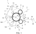
- FIG. 1 A particularly preferred embodiment of the installation 1 according to the invention is illustrated schematically in the figure 1 .
- the arrows on the figure 1 indicate the preferential direction of progression of the primary ply 3 and of the embossed ply 2 obtained from the latter, relative to the different devices and other components of said installation 1.
- the terms “upstream” and “downstream” used in the present description are preferably to be interpreted taking into consideration the direction of progression indicated by these arrows (and independently of the relative positioning in space of one or the other of said devices or components).
- said installation 1 comprises an embossing device 4 of the primary ply 3, and in particular of the right side 3A of the latter, using a heated embossing cylinder 5 (i.e. -say heating).
- Said embossing cylinder 5 is advantageously metallic, for example steel, with or without surface treatment.
- the diameter of the embossing cylinder 5 is typically between 200 and 1000 mm.
- the embossing cylinder 5 is provided with an internal heating system (not illustrated) to bring the surface of said embossing cylinder 5 to a temperature predefined, preferably between 50 C and 250°C.
- said installation 1 also includes a system for controlling and regulating (not illustrated) the temperature of the surface of the embossing cylinder 5.
- the embossing cylinder 5 is also provided on its surface with a pattern engraved in negative, the general appearance of which is not specifically limited, and the depth of which average is typically between 1 and 50 mm.
- said embossing cylinder 5 is removable and interchangeable, in order to ensure easy maintenance or replacement, for example by an embossing cylinder 5 of different diameter and/or bearing on its surface a different engraved pattern.
- said embossing device 4 of the installation 1 comprises a compression band 6. Positioned facing said embossing cylinder 5, and in particular facing a portion of the surface of the latter , said compression band 6 is designed and arranged to come into surface contact with said reverse side 3B of the primary ply 3 and exert a first compression force on said right side 3A in contact with the surface of said embossing cylinder 5 heated on at least a portion Pc of the perimeter of the latter. Said compression band 6 is thus advantageously intended to allow the implementation of the first compression step of the method according to the invention, as described in detail above.
- said compression band 6 is an advantageously flexible band, so that it can wrap at least partially around the embossing cylinder 5, and thus face to a non-negligible portion of the perimeter of the latter.
- said compression strip 6 is a continuous strip, that is to say endless, closed on itself, which makes it possible to facilitate the design of the installation 1 and to control its size.
- the compression strip 6 is a thermally conductive strip, and for example a metal strip, advantageously made of steel, and even more advantageously made of alloy steel.
- said strip of compression is on the contrary a thermally insulating strip, that is to say it has low thermal conductivity.
- the compression band 6 could then for example be produced by weaving or needling suitable mineral and/or organic fibers.
- the compression band 6 is removable and interchangeable, in order to ensure easy maintenance or replacement.
- the compression band 6 may advantageously have received a specific surface treatment, in particular to limit the risk of adhesion of the reverse side 3B of the primary ply 3 (for example, by deposition of a film of a material anti-adhesive, such as PFTE or other) and/or, where appropriate, to improve its thermal properties.
- said compression band 6 is preferably supported and guided by a plurality of detour cylinders 7A, 7B, 7C, the relative position of which is advantageously adjustable.
- said compression band 6 is kept partially wound around said embossing cylinder 5, over the length of said portion Pc of the perimeter of the latter, using a feed cylinder 8 and a return cylinder 9
- the feed cylinder 8 and/or the return cylinder 9, as well as possibly the detour cylinders 7A, 7B, 7C, may advantageously be provided on their surface with a coating of flexible material, for example elastomer.
- the installation 1 according to the invention being intended for the treatment of a pre-existing primary layer 3 of significant thickness, and in particular greater than (or equal to) 1 mm, said compression band 6 and said embossing cylinder 5 are arranged one relative to the other so as to authorize the interposition of the primary ply 3 between the compression band 6 and the surface of the embossing cylinder 5, when said primary ply 3 and compression band 6 are wound around said embossing cylinder 5 , along said perimeter portion Pc of the latter.
- the length of said portion Pc of the perimeter of the embossing cylinder 5 is predefined and adjustable.
- said portion Pc is advantageously defined by the position and the relative spacing of the inlet cylinder 8 and the outlet cylinder 9 along the periphery of the embossing cylinder 5.
- said portion Pc of the perimeter of said embossing cylinder 5 is advantageously defined by an arc angle ⁇ of the embossing cylinder 5 between approximately 72° and approximately 288° (i.e. between 1/5 and 415 of the perimeter of said embossing cylinder 5).
- said compression band 6 is arranged facing said embossing cylinder 5 and follows the contour of the latter over at least a quarter, and more preferably over three-quarters, of the perimeter of said embossing cylinder 5 (which corresponds to an arc angle ⁇ greater than or equal to 90°, and preferably equal to 270°).
- a first particularly extended compression zone of a width advantageously included between 440 and 1760 mm, depending in particular on the diameter of the embossing cylinder 5 chosen.
- the installation 1 comprises a first device 10 for controlling and regulating the intensity of said first compression force, corresponding to said first average pressure P1, exerted by the compression band.
- the first control and regulation device 10 is designed to control and regulate the tension of the compression band 6.
- said first control and regulation device 10 advantageously comprises a tensioning cylinder 11 , possibly confused with one of said detour cylinders 7A, 7B, 7C, and whose position is preferably controlled by a cylinder type actuator 12.
- said embossing device 4 comprises a counter-pressing cylinder 13 (or main counter-cylinder 13) designed and arranged to exert a second compression force, advantageously corresponding to a second predefined pressure P2, of said primary ply 3 between said embossing cylinder 5 and said main counter-pressing cylinder 13.
- said main counter-pressing cylinder 13 is intended to allow the implementation of the second compression step of the process according to the invention, as described above.
- the diameter of said main counter-pressing cylinder 13 could advantageously be between 100 and 500 mm.
- the main counter-pressing cylinder 13 is designed to exert said second compression force in a direction normal to said primary ply 3.
- said main counter-pressing cylinder 13 is positioned downstream of said surface contact, that is to say downstream of said embossing cylinder 5 and the first compression zone formed between the compression band 6 and the embossing cylinder 5 More precisely and in accordance with the embodiment illustrated in the figures, said main counter-pressing cylinder 13 is advantageously positioned immediately downstream of said surface contact, so that said second compression force corresponding to the pressure P2 is exerted so immediately following the first compression force corresponding to the pressure P1, which in particular makes it possible to avoid any untimely resumption of swelling, by elastic return, of said primary sheet, for an optimal final result in terms of dimension and aesthetics.
- said main counter-pressing cylinder 13 is arranged to exert said second compression force of said primary ply 3 between the embossing cylinder 5 and the main counter-pressing cylinder 13, said compression band 6 being interposed between the embossing cylinder 5 and the main counter-pressing cylinder 13.
- the main counter-cylinder 13 thus exerts said second compression force of the primary ply 3 on the surface of the embossing cylinder 5 through said compression band.
- said main counter-pressing cylinder 13 is merged with the return cylinder 9 of the compression band 6, so as to simplify the design and limit the bulk of the installation 1.
- said return cylinder 8 may on the contrary be distinct from said return cylinder 8 and be for example arranged between said return cylinder 9 and feed cylinder 8 (preferably however closer to the return cylinder 9 than to the feed cylinder 8), facing the portion Pc of the perimeter of the embossing roller 5 which is covered by said compression band 6, and in contact with the latter.
- the main counter-pressing cylinder 13 is provided on its surface with a covering of flexible material, for example elastomer, in particular so as to optimize the width of the second compression zone formed between the embossing cylinder 5 and the counter-pressing cylinder 13.
- main pressure cylinder 13 and to promote good transmission of mechanical forces.
- the installation 1 comprises a second device (not illustrated) for controlling and regulating the intensity of said second compression force, that is to say the second pressure P2, exerted by said counter-pressure cylinder main 13.
- Said second control and regulation device can be designed either to create and maintain constant a predefined relative spacing between the respective surfaces of the embossing cylinder 5 and the main counter-pressing cylinder 13, or to control the force exerted by a cylinder (or other, not illustrated) on the axis of said main counter-pressing cylinder 13 against said primary ply 3 and the embossing cylinder 5.
- said first 10 and second devices for controlling and regulating the The respective intensity of the first and second compression forces are distinct and are designed to be able to be controlled independently of each other.
- said embossing device 4 may comprise a counter-pressing cylinder, distinct from the main counter-pressing cylinder 13 which is intended for the exercise of the second compression force mentioned above, and is positioned upstream of said surface contact, c that is to say upstream of said embossing cylinder 5 and the first compression zone formed between the compression band 6 and the embossing cylinder 5.
- This optional counter-pressing cylinder is preferably designed and arranged to exert a pre-pressure force. compression, advantageously corresponding to a predefined pressure P3, of said primary layer 3 between said embossing cylinder 5 and said optional counter-pressing cylinder.
- this counter-pressing cylinder is intended to allow the implementation of the pre-compression step of the method according to the invention.
- this counter-pressure cylinder is then designed to exert said pre-compression force in a direction normal to said primary ply 3.
- said optional counter-pressing cylinder is arranged to exert said pre-compression force of said primary ply 3 between the embossing cylinder 5 and the counter-pressing cylinder, said compression band 6 being interposed between the embossing cylinder 5 and the counter-pressure cylinder.
- the counter-pressing cylinder thus exerts said pre-compression force of the primary ply 3 on the surface of the embossing cylinder 5 through said compression band 6.
- said counter-pressing cylinder is confused with the cylinder d 'feed 8 of the compression band 6, so as to simplify the design and limit the size of the installation 1. It will then advantageously constitute an inlet counter-cylinder.
- the optional counter-pressing cylinder is provided on its surface with a coating of flexible material, for example elastomer, in particular so as to optimize the width of the pre-compression zone formed between the embossing cylinder 5 and the counter-pressing cylinder. pressure cylinder, and to promote good transmission of mechanical forces.
- a coating of flexible material for example elastomer
- the installation 1 comprises a heating device 14 of said compression band 6, which is positioned behind said compression band 6, facing said perimeter portion Pc of the embossing cylinder 5, around which the band is wound compression band 6.
- the heating device 14 of said compression band 6 is provided with a temperature control and regulation system.
- said heating device 14 advantageously comprises a plurality of distinct heating elements 14A, 14B, 14C, preferably of the mid-infrared radiant heater type.
- said heating elements 14A, 14B, 14C are designed to be able to be controlled independently of each other, so as to ensure perfect control of the temperature of the compression band 6.
- said elements heaters 14A, 14B, 14C are each advantageously provided with their own temperature control and regulation system (not illustrated).
- the installation 1 of the invention comprises a preheating device 15 of said compression band 6.
- Said preheating device 15 is preferably arranged upstream of the embossing cylinder 5 (taking into consideration the direction of travel of the compression band 6), advantageously in the immediate vicinity of the latter.
- Said preheating device 15 of the compression band 6 can be of any known type, such as for example of the first radiant device 16 type.
- said preheating device 15 of said compression band 6 is provided with a system of temperature control and regulation.
- the installation 1 comprises a preheating device 17 of said primary layer 3.
- Said preheating device 17 is preferably arranged in upstream of the embossing cylinder 5 (taking into consideration the direction of travel of the compression band 6), advantageously in the immediate vicinity of the latter so as to maximize the continuity of the thermal supply to the primary layer 3, and opposite the right side 3A and 1 or the reverse side 3B of the primary ply 3 ( figure 1 ).
- Said device for preheating the primary layer 3 can be of any known type, such as for example of the second radiant device 18 type.
- said device for preheating 17 of the primary layer 3 is provided with a control and monitoring system. temperature regulation.
- said preheating device 17 of the primary layer 3 may comprise one or more infrared radiant heaters, arranged facing the right side 3A and/or the reverse side 3B of the primary layer 3, and preferably positioned immediately in upstream of the feed cylinder 8 of the compression band 6.
- the process and installation according to the invention allow the continuous, rapid, repeatable and efficient manufacture of embossed webs having an excellent embossing effect, from thermoformable webs of high thickness (greater than 1 mm) and very varied nature and composition.
- the embossed tablecloths obtained have an excellent surface finish and a particularly deep and well-defined embossed pattern.
- thermoformable material/textile complex for example a foam/textile complex
- the installation according to the invention is also particularly compact and relatively easy to maintain.
- An embossed tablecloth manufactured using a process and/or an installation in accordance with the invention, will find particular application in the fields of seat coverings for transport (automobile, etc.), furniture , sound and thermal insulation systems, or even in the field of decorative wall coverings.
- the invention finds its industrial application in processes and installations for the continuous manufacture of embossed sheets.
Landscapes
- Engineering & Computer Science (AREA)
- Mechanical Engineering (AREA)
- Treatment Of Fiber Materials (AREA)
- Shaping Of Tube Ends By Bending Or Straightening (AREA)
- Machines For Manufacturing Corrugated Board In Mechanical Paper-Making Processes (AREA)
Claims (15)
- Verfahren zur kontinuierlichen Herstellung einer geprägten Bahn (2) ausgehend von einer bereits vorhandenen Primärbahn (3) mit einer Dicke von mehr als 1 mm, wobei die Primärbahn (3) mindestens eine Schicht aus thermoformbarem Material umfasst und eine Vorderseite (3A) und eine gegenüberliegende Rückseite (3B) aufweist, bei dem die Primärbahn (3) einem Prägevorgang der Vorderseite (3A) mit Hilfe eines beheizten Prägezylinders (5) unterzogen wird, wobei der Prägevorgang mindestens einen ersten Kompressionsschritt der Vorderseite (3A) der Primärbahn (3) in Kontakt mit der Oberfläche des beheizten Prägezylinders (5) über mindestens einen Abschnitt (Pc) des Umfangs des letzteren mit Hilfe eines Kompressionsbandes (6) in Flächenkontakt mit der Rückseite (3B) der Primärbahn (3) umfasst, wobei das Verfahren dadurch gekennzeichnet ist, dass der Prägevorgang einen zweiten Kompressionsschritt der Primärbahn (3) zwischen dem Prägezylinder (5) und einem Hauptgegenpresszylinder (13) umfasst, wobei der zweite Kompressionsschritt unmittelbar auf den ersten Kompressionsschritt folgt, wobei der erste und der zweite Kompressionsschritt jeweils bei einem ersten Druck (P1) und einem zweiten Druck (P2) durchgeführt werden, die vordefiniert sind, wobei der zweite Druck (P2) größer als der erste Druck (P1) oder gleich diesem ist.
- Verfahren nach dem vorhergehenden Anspruch, dadurch gekennzeichnet, dass der erste Kompressionsschritt über eine Dauer von mindestens 1 s und vorzugsweise größer oder gleich 5 s durchgeführt wird.
- Verfahren nach Anspruch 1 oder 2, dadurch gekennzeichnet, dass während des zweiten Kompressionsschritts das Kompressionsband (6) zwischen dem Prägezylinder (5) und dem Hauptgegenpresszylinder (13) angeordnet ist.
- Verfahren nach einem der vorhergehenden Ansprüche, dadurch gekennzeichnet, dass der zweite Druck (P2) strikt höher ist als der erste Druck (P1).
- Verfahren nach einem der vorhergehenden Ansprüche, dadurch gekennzeichnet, dass das thermoformbare Material ein Schaumstoff oder ein Vliesmaterial, vernadelt oder nicht, ist.
- Verfahren nach einem der vorhergehenden Ansprüche, dadurch gekennzeichnet, dass die Primärbahn (3) eine Mehrschichtbahn ist, wobei die Primärbahn (3) vorzugsweise neben der Schicht aus thermoformbarem Material mindestens eine Textilschicht, z. B. gewebt oder nicht gewebt, umfasst.
- Verfahren nach einem der vorhergehenden Ansprüche, dadurch gekennzeichnet, dass es einen Schritt des Erwärmens des Kompressionsbandes (6) umfasst, um während des ersten Kompressionsschritts eine Wärmezufuhr zu der Primärbahn (3) von der Rückseite (3B) über das Kompressionsband (6) zu gewährleisten, wobei der Schritt des Erwärmens des Kompressionsbandes (6) vorzugsweise mit Hilfe einer Heizvorrichtung (14) durchgeführt wird, die hinter dem Kompressionsband (6) gegenüber dem Abschnitt (Pc) des Umfangs des Prägezylinders (5) positioniert ist.
- Verfahren nach einem der vorhergehenden Ansprüche, dadurch gekennzeichnet, dass es vor dem ersten Kompressionsschritt einen Schritt zum Vorwärmen der Primärbahn (3) umfasst.
- Anlage (1) zur kontinuierlichen Herstellung einer geprägten Bahn (2) aus einer bereits vorhandenen Primärbahn (3) mit einer Dicke von mehr als 1 mm, wobei die Primärbahn (3) mindestens eine Schicht aus thermoformbarem Material umfasst und eine Vorderseite (3A) und eine gegenüberliegende Rückseite (3B) aufweist, die Anlage (1) eine Vorrichtung (4) zum Prägen der Vorderseite (3) mit Hilfe eines beheizten Prägezylinders (5) umfasst, wobei die Prägevorrichtung (4) ein Kompressionsband (6) umfasst, das so konzipiert und angeordnet ist, dass es in Flächenkontakt mit der Rückseite (3B) der Primärbahn (3) kommt und eine erste Kompressionskraft, entsprechend einem ersten vordefinierten Druck (P1), auf die Vorderseite (3A) in Kontakt mit der Oberfläche des beheizten Prägezylinders (5) über mindestens einen Teil (Pc) des Umfangs des letzteren ausübt, wobei die Anlage (1) dadurch gekennzeichnet ist, dass die Prägevorrichtung (4) einen Hauptgegenpresszylinder (13) umfasst, der stromabwärts des besagten Flächenkontakts positioniert und so konzipiert und angeordnet ist, dass er eine zweite Kompressionskraft ausübt, entsprechend einem vordefinierten zweiten Druck (P2), der Primärbahn (3) zwischen dem Prägezylinder (5) und dem Hauptgegenpresszylinder (13), wobei der zweite Druck (P2) größer oder gleich dem ersten Druck (P1) ist.
- Anlage (1) nach dem vorhergehenden Anspruch, dadurch gekennzeichnet, dass das Kompressionsband (6) gegenüber dem Prägezylinder (5) angeordnet ist und der Kontur des Prägezylinders (5) über mindestens ein Viertel, vorzugsweise über drei Viertel, des Umfangs des Prägezylinders (5) folgt.
- Anlage (1) nach einem der Ansprüche 9 oder 10, dadurch gekennzeichnet, dass sie eine erste Vorrichtung (10) zur Kontrolle und Regelung der Intensität der ersten Kompressionskraft umfasst.
- Anlage (1) nach einem der Ansprüche 9 bis 11, dadurch gekennzeichnet, dass sie eine zweite Vorrichtung zur Kontrolle und Regelung der Intensität der zweiten Kompressionskraft umfasst.
- Anlage (1) nach einem der Ansprüche 9 bis 12, dadurch gekennzeichnet, dass der Hauptgegenpresszylinder (13) so angeordnet ist, dass er die zweite Kompressionskraft der Primärbahn (3) zwischen dem Prägezylinder (5) und dem Hauptgegenpresszylinder (13) ausübt, wobei das Kompressionsband (6) zwischen dem Prägezylinder (5) und dem Hauptgegenpresszylinder (13) angeordnet ist.
- Anlage (1) nach einem der Ansprüche 9 bis 13, dadurch gekennzeichnet, dass sie eine Heizvorrichtung (14) für das Kompressionsband (6) umfasst, die hinter dem Kompressionsband (6) gegenüber dem Abschnitt (Pc) des Umfangs des Prägezylinders (5) positioniert ist.
- Anlage (1) nach einem der Ansprüche 9 bis 14, dadurch gekennzeichnet, dass sie eine Vorheizvorrichtung (17) für die Primärbahn (3) umfasst, die stromaufwärts des Prägezylinders (5) angeordnet ist.
Applications Claiming Priority (2)
| Application Number | Priority Date | Filing Date | Title |
|---|---|---|---|
| FR1850266A FR3076758B1 (fr) | 2018-01-12 | 2018-01-12 | Procede de fabrication en continu d'une nappe gaufree et installation afferente |
| PCT/FR2019/050062 WO2019138197A1 (fr) | 2018-01-12 | 2019-01-11 | Procede de fabrication en continu d'une nappe gaufree et installation afferente |
Publications (2)
| Publication Number | Publication Date |
|---|---|
| EP3737547A1 EP3737547A1 (de) | 2020-11-18 |
| EP3737547B1 true EP3737547B1 (de) | 2024-03-06 |
Family
ID=61873529
Family Applications (1)
| Application Number | Title | Priority Date | Filing Date |
|---|---|---|---|
| EP19703170.1A Active EP3737547B1 (de) | 2018-01-12 | 2019-01-11 | Verfahren zur kontinuierlichen herstellung einer prägefolienbahn und zugehörige anlage |
Country Status (6)
| Country | Link |
|---|---|
| US (1) | US20210187820A1 (de) |
| EP (1) | EP3737547B1 (de) |
| FR (1) | FR3076758B1 (de) |
| MA (1) | MA51564A (de) |
| PT (1) | PT3737547T (de) |
| WO (1) | WO2019138197A1 (de) |
Families Citing this family (1)
| Publication number | Priority date | Publication date | Assignee | Title |
|---|---|---|---|---|
| DE102021127174A1 (de) | 2021-10-20 | 2022-08-25 | Voith Patent Gmbh | Vorrichtung zur Herstellung einer Folie |
Family Cites Families (8)
| Publication number | Priority date | Publication date | Assignee | Title |
|---|---|---|---|---|
| US2446771A (en) * | 1946-12-31 | 1948-08-10 | Boston Woven Hose & Rubber Com | Method of imparting surface effects to thermoplastic sheets |
| US3241182A (en) * | 1963-04-23 | 1966-03-22 | Kessler Milton | Apparatus for the production of heavily embossed, thick plastic mats |
| JPH05309682A (ja) * | 1992-05-01 | 1993-11-22 | Nitto Denko Corp | 加硫ゴムシートの連続製造方法 |
| JPH08309851A (ja) * | 1995-05-17 | 1996-11-26 | Idemitsu Petrochem Co Ltd | エンボスパターンを有する面状熱可塑性樹脂の製造方法及び装置 |
| ATE209098T1 (de) * | 1996-06-26 | 2001-12-15 | Idemitsu Petrochemical Co | Verfahren zum musterprägen einer folie und vorrichtung zur musterprägung |
| JP2000211024A (ja) * | 1999-01-22 | 2000-08-02 | Idemitsu Petrochem Co Ltd | マイクロエンボスシ―トの製造方法及びその装置 |
| JP4441803B2 (ja) * | 2002-12-12 | 2010-03-31 | 株式会社シーティーイー | 熱可塑性合成樹脂製シート又はフイルムの製造方法およびその装置 |
| US20050104253A1 (en) * | 2003-11-11 | 2005-05-19 | Ryuichi Katsumoto | Production method and production apparatus of pattern-indented sheet |
-
2018
- 2018-01-12 FR FR1850266A patent/FR3076758B1/fr active Active
-
2019
- 2019-01-11 MA MA051564A patent/MA51564A/fr unknown
- 2019-01-11 EP EP19703170.1A patent/EP3737547B1/de active Active
- 2019-01-11 US US16/961,693 patent/US20210187820A1/en not_active Abandoned
- 2019-01-11 PT PT197031701T patent/PT3737547T/pt unknown
- 2019-01-11 WO PCT/FR2019/050062 patent/WO2019138197A1/fr unknown
Also Published As
| Publication number | Publication date |
|---|---|
| WO2019138197A1 (fr) | 2019-07-18 |
| EP3737547A1 (de) | 2020-11-18 |
| PT3737547T (pt) | 2024-05-31 |
| FR3076758B1 (fr) | 2021-03-05 |
| FR3076758A1 (fr) | 2019-07-19 |
| US20210187820A1 (en) | 2021-06-24 |
| MA51564A (fr) | 2021-04-21 |
Similar Documents
| Publication | Publication Date | Title |
|---|---|---|
| CA2776258C (fr) | Procede et dispositif pour la fabrication automatisee de preformes fibreuses seches | |
| EP1140376B1 (de) | Verfahren und vorrichtung zum kontinuierlichen beschichten zumindest eines metallischen bandes mit flüssigkeitsfilm aus vernetzbarem polymer | |
| FR2758340A1 (fr) | Procede et dispositif de fabrication de plaques composites | |
| EP1001848B1 (de) | Verfahren und vorrichtung zum kontinuierlichen beschichten eines metallbandes mit einem film aus vernetzbarem fliessfähigem polymer | |
| EP3737547B1 (de) | Verfahren zur kontinuierlichen herstellung einer prägefolienbahn und zugehörige anlage | |
| FR2476543A1 (fr) | Procede de fabrication d'une feuille stratifiee | |
| EP3380309A1 (de) | Faserauftragskopf mit einer flexiblen walze mit einer metallischen aussenschicht | |
| CH616366A5 (de) | ||
| EP1140375B1 (de) | Verfahren und vorrichtung zum kontinuierlichen beschichten eines metallischen bandes mit flüssigkeitsfilm aus vernetzbarem polymer | |
| FR2893531A1 (fr) | Procede de consolidation en continu pour l'obtention d'un materiau stratifie et dispositif pour sa mise en oeuvre | |
| EP0794050B1 (de) | Gewelltes Verpackungsmaterial und Verfahren und Vorrichtung zur Herstellung eines gewellten Verpackungsmaterials | |
| FR2901200A1 (fr) | Procede de fabrication d'un complexe de coiffe pour un siege de vehicule; complexe de coiffe obtenu a partir d'un tel procede et siege de vehicule comprenant une coiffe obtenue par un tel procede | |
| FR3067954B1 (fr) | Procede de realisation en continu d'un motif a la surface d'un substrat souple et installation afferente | |
| FR2891763A1 (fr) | Procede et installation de pose d'une couche de polyurethane expanse sur un revetement de garnissage d'un equipement de vehicule et complexe de revetement | |
| FR3035022A1 (fr) | Complexe textile incluant une ame tissee a base de fils de haute tenacite, et procede de fabrication d'un tel complexe | |
| FR2850368A1 (fr) | Procede de depose sur un support de couches fibreuses successives inclinees, a partir d'une bande continue | |
| BE553354A (de) | ||
| EP2004403B1 (de) | Verfahren zur herstellung eines komplexes mit einer eine bestimmte struktur aufweisenden stützschicht | |
| FR3093669A1 (fr) | Procédé de fabrication d’un renfort fibreux pré-imprégné à partir d’un non-tissé thermoplastique et d’un renfort de fibres naturelles | |
| BE678593A (de) | ||
| FR2515104A1 (fr) | Installation perfectionnee pour la fabrication en continu de panneaux en fibres de bois par un procede a sec | |
| FR2712839A1 (fr) | Procédé et dispositif de fabrication en continu de tôles métalliques dites "tôles sandwich", et tôles ainsi obtenues. | |
| BE710039A (de) | ||
| FR2554836A1 (fr) | Etoffe en matiere plastique et procede et appareil pour sa fabrication | |
| CH473272A (fr) | Procédé de fabrication d'un matériau en feuille |
Legal Events
| Date | Code | Title | Description |
|---|---|---|---|
| STAA | Information on the status of an ep patent application or granted ep patent |
Free format text: STATUS: UNKNOWN |
|
| STAA | Information on the status of an ep patent application or granted ep patent |
Free format text: STATUS: THE INTERNATIONAL PUBLICATION HAS BEEN MADE |
|
| PUAI | Public reference made under article 153(3) epc to a published international application that has entered the european phase |
Free format text: ORIGINAL CODE: 0009012 |
|
| STAA | Information on the status of an ep patent application or granted ep patent |
Free format text: STATUS: REQUEST FOR EXAMINATION WAS MADE |
|
| 17P | Request for examination filed |
Effective date: 20200708 |
|
| AK | Designated contracting states |
Kind code of ref document: A1 Designated state(s): AL AT BE BG CH CY CZ DE DK EE ES FI FR GB GR HR HU IE IS IT LI LT LU LV MC MK MT NL NO PL PT RO RS SE SI SK SM TR |
|
| AX | Request for extension of the european patent |
Extension state: BA ME |
|
| DAX | Request for extension of the european patent (deleted) | ||
| RAV | Requested validation state of the european patent: fee paid |
Extension state: MA Effective date: 20200708 |
|
| RIC1 | Information provided on ipc code assigned before grant |
Ipc: B29C 43/48 20060101ALI20221025BHEP Ipc: B29C 43/58 20060101ALI20221025BHEP Ipc: B29C 43/46 20060101ALI20221025BHEP Ipc: B29C 43/26 20060101ALI20221025BHEP Ipc: B29C 43/30 20060101ALI20221025BHEP Ipc: B29C 43/24 20060101ALI20221025BHEP Ipc: B29C 59/04 20060101AFI20221025BHEP |
|
| GRAP | Despatch of communication of intention to grant a patent |
Free format text: ORIGINAL CODE: EPIDOSNIGR1 |
|
| STAA | Information on the status of an ep patent application or granted ep patent |
Free format text: STATUS: GRANT OF PATENT IS INTENDED |
|
| INTG | Intention to grant announced |
Effective date: 20221219 |
|
| GRAS | Grant fee paid |
Free format text: ORIGINAL CODE: EPIDOSNIGR3 |
|
| GRAJ | Information related to disapproval of communication of intention to grant by the applicant or resumption of examination proceedings by the epo deleted |
Free format text: ORIGINAL CODE: EPIDOSDIGR1 |
|
| GRAL | Information related to payment of fee for publishing/printing deleted |
Free format text: ORIGINAL CODE: EPIDOSDIGR3 |
|
| STAA | Information on the status of an ep patent application or granted ep patent |
Free format text: STATUS: REQUEST FOR EXAMINATION WAS MADE |
|
| INTC | Intention to grant announced (deleted) | ||
| P01 | Opt-out of the competence of the unified patent court (upc) registered |
Effective date: 20230524 |
|
| GRAP | Despatch of communication of intention to grant a patent |
Free format text: ORIGINAL CODE: EPIDOSNIGR1 |
|
| STAA | Information on the status of an ep patent application or granted ep patent |
Free format text: STATUS: GRANT OF PATENT IS INTENDED |
|
| INTG | Intention to grant announced |
Effective date: 20230831 |
|
| GRAA | (expected) grant |
Free format text: ORIGINAL CODE: 0009210 |
|
| STAA | Information on the status of an ep patent application or granted ep patent |
Free format text: STATUS: THE PATENT HAS BEEN GRANTED |
|
| AK | Designated contracting states |
Kind code of ref document: B1 Designated state(s): AL AT BE BG CH CY CZ DE DK EE ES FI FR GB GR HR HU IE IS IT LI LT LU LV MC MK MT NL NO PL PT RO RS SE SI SK SM TR |
|
| REG | Reference to a national code |
Ref country code: CH Ref legal event code: EP |
|
| REG | Reference to a national code |
Ref country code: DE Ref legal event code: R096 Ref document number: 602019047700 Country of ref document: DE |
|
| REG | Reference to a national code |
Ref country code: IE Ref legal event code: FG4D Free format text: LANGUAGE OF EP DOCUMENT: FRENCH |
|
| REG | Reference to a national code |
Ref country code: PT Ref legal event code: SC4A Ref document number: 3737547 Country of ref document: PT Date of ref document: 20240531 Kind code of ref document: T Free format text: AVAILABILITY OF NATIONAL TRANSLATION Effective date: 20240522 |
|
| REG | Reference to a national code |
Ref country code: LT Ref legal event code: MG9D |