EP3736918A1 - Steckverbinder - Google Patents
Steckverbinder Download PDFInfo
- Publication number
- EP3736918A1 EP3736918A1 EP20172944.9A EP20172944A EP3736918A1 EP 3736918 A1 EP3736918 A1 EP 3736918A1 EP 20172944 A EP20172944 A EP 20172944A EP 3736918 A1 EP3736918 A1 EP 3736918A1
- Authority
- EP
- European Patent Office
- Prior art keywords
- connector part
- connector
- contact
- axis
- rotation
- Prior art date
- Legal status (The legal status is an assumption and is not a legal conclusion. Google has not performed a legal analysis and makes no representation as to the accuracy of the status listed.)
- Granted
Links
Images





Classifications
-
- H—ELECTRICITY
- H01—ELECTRIC ELEMENTS
- H01R—ELECTRICALLY-CONDUCTIVE CONNECTIONS; STRUCTURAL ASSOCIATIONS OF A PLURALITY OF MUTUALLY-INSULATED ELECTRICAL CONNECTING ELEMENTS; COUPLING DEVICES; CURRENT COLLECTORS
- H01R35/00—Flexible or turnable line connectors, i.e. the rotation angle being limited
- H01R35/04—Turnable line connectors with limited rotation angle with frictional contact members
-
- H—ELECTRICITY
- H01—ELECTRIC ELEMENTS
- H01R—ELECTRICALLY-CONDUCTIVE CONNECTIONS; STRUCTURAL ASSOCIATIONS OF A PLURALITY OF MUTUALLY-INSULATED ELECTRICAL CONNECTING ELEMENTS; COUPLING DEVICES; CURRENT COLLECTORS
- H01R12/00—Structural associations of a plurality of mutually-insulated electrical connecting elements, specially adapted for printed circuits, e.g. printed circuit boards [PCB], flat or ribbon cables, or like generally planar structures, e.g. terminal strips, terminal blocks; Coupling devices specially adapted for printed circuits, flat or ribbon cables, or like generally planar structures; Terminals specially adapted for contact with, or insertion into, printed circuits, flat or ribbon cables, or like generally planar structures
- H01R12/50—Fixed connections
- H01R12/51—Fixed connections for rigid printed circuits or like structures
- H01R12/55—Fixed connections for rigid printed circuits or like structures characterised by the terminals
- H01R12/57—Fixed connections for rigid printed circuits or like structures characterised by the terminals surface mounting terminals
-
- H—ELECTRICITY
- H01—ELECTRIC ELEMENTS
- H01R—ELECTRICALLY-CONDUCTIVE CONNECTIONS; STRUCTURAL ASSOCIATIONS OF A PLURALITY OF MUTUALLY-INSULATED ELECTRICAL CONNECTING ELEMENTS; COUPLING DEVICES; CURRENT COLLECTORS
- H01R13/00—Details of coupling devices of the kinds covered by groups H01R12/70 or H01R24/00 - H01R33/00
- H01R13/62—Means for facilitating engagement or disengagement of coupling parts or for holding them in engagement
- H01R13/627—Snap or like fastening
- H01R13/6277—Snap or like fastening comprising annular latching means, e.g. ring snapping in an annular groove
-
- H—ELECTRICITY
- H01—ELECTRIC ELEMENTS
- H01R—ELECTRICALLY-CONDUCTIVE CONNECTIONS; STRUCTURAL ASSOCIATIONS OF A PLURALITY OF MUTUALLY-INSULATED ELECTRICAL CONNECTING ELEMENTS; COUPLING DEVICES; CURRENT COLLECTORS
- H01R24/00—Two-part coupling devices, or either of their cooperating parts, characterised by their overall structure
- H01R24/38—Two-part coupling devices, or either of their cooperating parts, characterised by their overall structure having concentrically or coaxially arranged contacts
Definitions
- the present invention relates to a connector for connecting a single or multi-core electrical line, comprising a first connector part and a second connector part, each having at least one contact element and being connectable to one another in such a way that at least one contact element of the first connector part is a contact element of the second connector part touches an electrical contact.
- Such connectors are used, for example, for connecting sensors, actuators or the like to associated control devices.
- a connection via a connector increases flexibility compared to systems in which a cable is permanently connected to a device housing.
- the first connector part in the connected state, is rotatably guided around an axis of rotation on the second connector part, with at least the at least one contact element of the first connector part being designed as a curved conductor track whose center of curvature coincides at least essentially with the axis of rotation.
- the first connector part can thus be aligned by turning it in the way that is most favorable for the respective installation location. This turning can take place after the plug-in connection process, which results in a particularly high degree of flexibility.
- the first connector part has a preferably flat contact surface which runs transversely to the axis of rotation and to which the curved conductor track is applied.
- one of the connector parts is a plug and the other connector part is a socket or a coupling. Furthermore, the first connector part can be guided on the second connector part by means of a sliding guide. The contact elements of the first connector part and the second connector part are preferably connected to respective connection and / or line elements of the plug connector.
- the contact surface can be formed on a connection body of the first connector part which is made of an electrically insulating material, preferably for example a fiber-reinforced plastic. Such a use of an insulating material for the connection body enables particularly simple and inexpensive manufacture.
- the connection body can form a base body of the first connector part or be placed on such a base body.
- the curved conductor track preferably has an annular or partially annular course.
- the curved conductor track extends over an angular range of at least 90 °, preferably of at least 180 ° and particularly preferably of 360 °.
- the first connector part and the second connector part each have a plurality of contact elements, with associated contact elements of the first connector part and the second connector part touching each other for electrical contact in the connected state of the connector parts and with at least two contact elements of the first connector part as concentric conductor tracks are executed.
- the concentric arrangement of the Conductor tracks ensure that the assignment of the contacting contact elements does not change when the first connector part is rotated relative to the second connector part. With such a connector, multi-core lines can also be reliably connected.
- the invention proves to be particularly advantageous if the first connector part has a cable connection which defines a cable axis inclined with respect to the axis of rotation. This enables the cable to be led away from the sensor housing at an angle, which is particularly advantageous when the installation space is restricted.
- the cable axis can be inclined by approximately 45 ° with respect to the axis of rotation. Due to the rotatability of the first connector part, the cable axis can be aligned after completion of the assembly as it is most favorable for the respective installation situation.
- the first connector part can by means of a closure, e.g. B. a snap lock, can be locked on the second connector part. This prevents unintentional disconnection of the connector while the associated device is in operation.
- a closure e.g. B. a snap lock
- the first connector part can first be locked to the second connector part and then turned into position.
- a holding device for fixing at least one of the connector parts to a sensor housing for example a retaining clip, can be provided.
- the contact elements are preferably prestressed against one another in the axial direction by at least one elastic element. Due to the preload, the contact is not sensitive to tolerances and is therefore particularly reliable. In particular, reliable contact is guaranteed even with temperature fluctuations.
- the at least one contact element of the second connector part can be designed as a spring contact in order to ensure such a bias.
- the at least one contact element of the second connector part can comprise a resilient metal tongue.
- the axial preload could also be brought about by a separate spring element which is effective between the connector parts.
- a further embodiment of the invention provides that the second connector part has a circuit board and the at least one contact element of the second connector part is soldered onto the circuit board.
- This configuration is particularly suitable for applications in which the second connector part in a device housing such.
- B. a sensor housing is integrated.
- Forming the contact element of the second connector part as a surface-mounted device (SMD) results in a particularly space-saving and inexpensive construction.
- SMD surface-mounted device
- the first connector part comprises a preferably at least substantially cylindrical base body which is rotationally symmetrical with respect to the axis of rotation and which is designed to be inserted into a receptacle of the second connector part.
- the curved conductor track or a connection body provided with it can be arranged on an end face of the base body.
- the receptacle can comprise a simple sleeve. By providing longitudinal slots in the sleeve wall, the necessary freedom of movement for a latching process can be created.
- a latching groove extending around the axis of rotation can be provided on the base body and interacts with a latching lug which is arranged on an inner wall of the receptacle. This enables a particularly simple locking of the two connector parts with one another.
- a special embodiment of the invention provides that a projecting centering element is arranged on the first connector part and a centering receptacle that matches the centering element is arranged on the second connector part.
- a projecting centering element can be arranged on the second connector part and a centering receptacle matching the centering element can be arranged on the first connector part.
- the centering element can be designed as a simple pin or bolt arranged collinearly with the axis of rotation. The reliability of the connection is increased by the centering element. In particular, a transverse offset of the two connector parts is avoided.
- the centering element and the centering receptacle can form additional electrical contact elements.
- the centering element and the centering receptacle can consist of conductive material and be connected to connection and / or line elements.
- the at least one curved conductor track is electrically connected or connectable to a line element which, for. B. is arranged at a rear end region of the first connector part or a connection body.
- the line element can be connected directly or indirectly, for example by soldering or crimping, to a wire of a connection cable.
- the invention also relates to an optoelectronic sensor with a sensor housing and a plug connector for connecting a cable to the optoelectronic sensor, the plug connector being designed as described above.
- the fact that the connector parts of the connector can also be rotated relative to one another after the sensor has been connected and that there is reliable electrical contacting regardless of the rotational position due to the curved conductor track means that the cable position can be adapted to the installation situation. A particularly careful and correspondingly complex prior angular alignment is not necessary.
- Such assembly problems due to of confined spaces occur relatively often with optoelectronic sensors such as light sensors, light barriers or light grids.
- the second connector part can be attached to the sensor housing and in particular integrated into it. That is to say, a connector according to the invention can be designed as a built-in connector. In this embodiment, the advantage of the later rotatability of the connector parts comes into its own.
- the second connector part is mounted in the sensor housing with freedom of movement.
- Such a movable mounting enables tolerance compensation.
- the first connector part can be a cable-side connector part, while the second connector part can be a sensor-side connector part.
- the in Fig. 1 only partially shown optoelectronic sensor 11 is connected by means of a connector 13 according to the invention to a cable (not shown) and via this to a control unit, also not shown, e.g. B. a safety controller and / or an evaluation unit or a combined control and evaluation unit connected.
- the optoelectronic sensor 11 can be designed, for example, as a light scanner, light barrier or light grid (or possibly a part thereof).
- the plug connector 13 has a first connector part 15 and a second connector part 16.
- the first connector part 15 is designed as a plug
- the second connector part 16 is designed as an associated socket, ie as a receptacle for the plug.
- the second connector part 16 is integrated into a sensor housing 17 of the optoelectronic sensor 11, as shown.
- the second connector part 16 has a sleeve 14 which, as in FIG Fig. 5 is recognizably provided with three slots 18 distributed along the circumference.
- a latching lug 21 protrudes from an inner wall 19 of the sleeve 14 and extends in the circumferential direction and is only interrupted by the slots 18.
- the second connector part 16 comprises a printed circuit board 22 with a plurality of contact elements 24 applied to it. It is understood that the number of contact elements 24 can vary depending on the application.
- the contact elements 24 are preferably soldered onto the circuit board 22. In particular, the contact elements 24 can be applied to the circuit board 22 by means of SMD technology.
- the contact elements 24 are connected via the printed circuit board 22 to line and / or connection elements (not shown) of the plug connector 11.
- the in Fig. 1 The illustrated embodiment, the contact elements 24 include resilient metal tongues and therefore form spring contacts.
- the second connector part 16 is preferably mounted in the sensor housing 17 with room to move in order to enable tolerance compensation.
- the first connector part 15 comprises an at least essentially cylindrical base body 25 which can be inserted into the sleeve 14 of the second connector part 16.
- a circumferential latching groove 27 is located on a jacket surface 26 of the base body 25 and cooperates with the latching lug 21 of the second connector part 16.
- the connected state of the connector parts 15, 16 shown here engages the locking lug 21 in the locking groove 27.
- the first connector part 15 is guided on the second connector part 16 so as to be rotatable about an axis of rotation R.
- the first connector part 15 has a cable connection 29 which defines a cable axis K which is inclined by approximately 45 ° with respect to the axis of rotation R.
- the cable connection 29 has a cable duct 30 and a plurality of connection pins 33.
- an external thread 34 is provided, onto which a union nut, not shown, can be screwed.
- a connection body 35 made of an electrically insulating material such as a fiber-reinforced plastic is arranged on a front side of the base body 25.
- An arrangement of concentric conductor tracks 38 is applied to the end face 37 of the connection body 35 facing away from the base body 25.
- the conductor tracks 38 can be seen to be partially annular and concentric with respect to the axis of rotation R. At the in Fig. 3 The embodiment shown, they extend over an angular range of approximately 270 °.
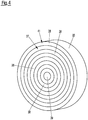
- Fig. 4 an embodiment in which the conductor tracks 38 extend over an angular range of 360 °, that is to say over the full circumference.
- the concentric conductor tracks 38 there is a central circular conductor surface 39.
- the conductor tracks 38 and the conductor surface 39 are each electrically connected to associated connection pins 33 via line elements 40 guided through the connection body 35.
- the conductor tracks 38 and the conductor surface 39 form contact elements 41 of the first connector part 15.
- the first connector part 15 Since the first connector part 15 is rotatably mounted on the second connector part 16 and the conductor tracks 38 run concentrically with respect to the axis of rotation R, the first connector part 15 can be rotated after plugging in without the electrical connection To influence contacting. This is particularly important because the cable is led out of the sensor housing at an angle and thus the cable routing can be adapted to the installation conditions by rotating the first connector part 15.
- a user can first attach the sensor housing 17 to a support component, a wall or the like, then insert the first connector part 15 into the second connector part 16 and then turn the first connector part 15 so that the inclined cable routing is in the Is particularly favorable with regard to the installation position.
- the contact elements 24 of the second connector part 16 can be held together when applied to the circuit board 22 by a contact strip 45 which is used for connection and alignment. After the contact elements 24 have been soldered, the contact strip 45 is removed so that the in Fig. 7 shown condition. The contacting of the conductor tracks 38 and the conductor surface 39 by the contact elements 24 is shown in FIG Fig. 8 illustrated.
- Fig. 9 shows an alternatively designed connector 13 'according to the invention, which is designed similar to that in FIG Fig. 1
- the plug connector 13 shown has a centering pin 47 which is arranged on the first connector part 15 and is collinear with the axis of rotation R and can be inserted into a matching centering receptacle 49 of the circuit board 22. This largely prevents the connector parts 15, 16 from being offset transversely to the axis of rotation R. If necessary, the centering pin 47 can also form an additional electrical contact.
- a spring element can be arranged for axially acting on the circuit board 22 in the direction of the inserted first connector part 15. Such a spring element could also be used in the in Fig. 1 be provided embodiment shown.
- the invention enables a space-saving and flexible connection of optoelectronic sensors 11 and other devices to control devices, with the possibility of simple assembly and subsequent correction of the cable routing.
- the plug is located on the sensor-side part of the connector and the socket is located on the cable-side part.
- individual or several elements of the connector can also be provided on the other connector part 15, 16 than is explicitly described here.
- the concentric conductor tracks can also be provided on the sensor-side connector part and the complementary contact elements on the cable-side part.
- the locking connection can be configured the other way around than described above, ie the locking lug can be on the cable-side part of the connector and the locking groove on the sensor-side part.
Landscapes
- Details Of Connecting Devices For Male And Female Coupling (AREA)
Abstract
Description
- Die vorliegende Erfindung betrifft einen Steckverbinder zum Verbinden einer ein- oder mehradrigen elektrischen Leitung, umfassend ein erstes Verbinderteil und ein zweites Verbinderteil, die jeweils wenigstens ein Kontaktelement aufweisen und derart miteinander verbindbar sind, dass zumindest ein Kontaktelement des ersten Verbinderteils ein Kontaktelement des zweiten Verbinderteils für einen elektrischen Kontakt berührt.
- Derartige Steckverbinder werden beispielsweise zum Anschließen von Sensoren, Aktoren oder dergleichen an zugehörige Steuerungseinrichtungen verwendet. Ein Anschluss über einen Steckverbinder erhöht die Flexibilität gegenüber Systemen, bei welchen ein Kabel fest mit einem Gerätegehäuse verbunden ist.
- In vielen Anwendungssituationen besteht für die Montage von Sensoren oder dergleichen nur wenig Platz. Ein besonderes Problem ist hierbei das vom Gehäuse abstehende Kabel. Wenn dessen Ausrichtung relativ zum Sensorgehäuse ungünstig ist, kann eine Montage an einem vorgegebenen Ort erschwert oder sogar unmöglich sein. Ferner ist das Montieren von Sensoren, die bereits verkabelt sind, generell mit Schwierigkeiten verbunden.
- Es ist eine Aufgabe der Erfindung, einen Steckverbinder anzugeben, der eine vereinfachte Montage von Sensoren und dergleichen auch unter beengten Platzverhältnissen ermöglicht.
- Die Lösung der Aufgabe erfolgt durch einen Steckverbinder mit den Merkmalen des Anspruchs 1.
- Erfindungsgemäß ist in dem verbundenen Zustand das erste Verbinderteil um eine Rotationsachse drehbar am zweiten Verbinderteil geführt, wobei zumindest das wenigstens eine Kontaktelement des ersten Verbinderteils als gekrümmte Leiterbahn ausgeführt ist, deren Krümmungsmittelpunkt zumindest im Wesentlichen mit der Rotationsachse zusammenfällt.
- Dadurch bleiben bei einer Drehung der Verbinderteile relativ zueinander die Kontaktelemente in Berührung, so dass sich keine Änderung der elektrischen Kontaktierung ergibt. Das erste Verbinderteil kann somit durch Drehen derart ausgerichtet werden, wie es für den jeweiligen Montageort am günstigsten ist. Dieses Zurechtdrehen kann nach dem Steckverbindungsvorgang erfolgen, wodurch sich eine besonders hohe Flexibilität ergibt. Bei der Montage des betreffenden Sensorgehäuses muss daher nicht auf die gewünschte Stellung des ersten Verbinderteils oder des Kabels geachtet werden.
- Erfindungsgemäß weist das erste Verbinderteil eine quer zu der Rotationsachse verlaufende, vorzugsweise ebene, Kontaktfläche auf, auf welche die gekrümmte Leiterbahn aufgebracht ist. Bei einem Zusammenstecken der Verbinderteile gelangt das Kontaktelement des zweiten Verbinderteils automatisch in Anlage an die gekrümmte Leiterbahn des ersten Verbinderteils.
- Es kann vorgesehen sein, dass eines der Verbinderteile ein Stecker und das andere Verbinderteil eine Buchse bzw. eine Kupplung ist. Weiterhin kann das erste Verbinderteil mittels einer Gleitführung an dem zweiten Verbinderteil geführt sein. Vorzugsweise sind die Kontaktelemente des ersten Verbinderteils und des zweiten Verbinderteils mit jeweiligen Anschluss- und/oder Leitungselementen des Steckverbinders verbunden.
- Weiterbildungen der Erfindung sind den abhängigen Ansprüchen, der Beschreibung sowie den beigefügten Zeichnungen zu entnehmen.
- Die Kontaktfläche kann an einem Anschlusskörper des ersten Verbinderteils ausgebildet sein, der aus einem elektrisch isolierenden Material, bevorzugt zum Beispiel aus einem faserverstärkten Kunststoff, gefertigt ist. Eine solche Verwendung eines isolierenden Materials für den Anschlusskörper ermöglicht eine besonders einfache und kostengünstige Herstellung. Der Anschlusskörper kann einen Grundkörper des ersten Verbinderteils bilden oder auf einen solchen Grundkörper aufgesetzt sein.
- Bevorzugt weist die gekrümmte Leiterbahn einen ringförmigen oder teilringförmigen Verlauf auf. Bei einer Drehung des ersten Verbinderteils um die Rotationsachse bleibt somit die elektrische Kontaktierung unverändert.
- Es kann vorgesehen sein, dass sich die gekrümmte Leiterbahn über einen Winkelbereich von wenigstens 90°, bevorzugt von wenigstens 180° und besonders bevorzugt von 360° erstreckt. Je größer der Winkelbereich ist, über welchen sich die gekrümmte Leiterbahn erstreckt, umso mehr Spielraum besteht für eine Drehung des ersten Verbinderteils. Wenn sich die gekrümmte Leiterbahn über einen Winkelbereich von 360° erstreckt, kann im Prinzip eine beliebige Drehung des ersten Verbinderteils erfolgen.
- Gemäß einer Ausführungsform der Erfindung weisen das erste Verbinderteil und das zweite Verbinderteil jeweils mehrere Kontaktelemente auf, wobei im verbundenen Zustand der Verbinderteile zugehörige Kontaktelemente des ersten Verbinderteils und des zweiten Verbinderteils einander für einen elektrischen Kontakt berühren und wobei wenigstens zwei Kontaktelemente des ersten Verbinderteils als konzentrische Leiterbahnen ausgeführt sind. Die konzentrische Anordnung der Leiterbahnen stellt sicher, dass sich an der Zuordnung der einander berührenden Kontaktelemente nichts ändert, wenn das erste Verbinderteil relativ zum zweiten Verbinderteil gedreht wird. Mit einem derartigen Steckverbinder können auch mehradrige Leitungen zuverlässig verbunden werden.
- Besonders vorteilhaft erweist sich die Erfindung, wenn das erste Verbinderteil einen Kabelanschluss aufweist, der eine gegenüber der Rotationsachse geneigte Kabelachse definiert. Dies ermöglicht ein schräges Wegführen des Kabels vom Sensorgehäuse, was insbesondere bei beengtem Einbauraum von Vorteil ist. Insbesondere kann die Kabelachse um etwa 45° gegenüber der Rotationsachse geneigt sein. Aufgrund der Drehbarkeit des ersten Verbinderteils kann die Kabelachse nach dem Abschluss der Montage so ausgerichtet werden, wie es für die jeweilige Einbausituation am günstigsten ist.
- Das erste Verbinderteil kann mittels eines Verschlusses, z. B. eines Rastverschlusses, am zweiten Verbinderteil arretierbar sein. Dadurch wird ein unbeabsichtigtes Trennen des Steckverbinders während des Betriebs des zugehörigen Geräts vermieden. Beim Anschluss des Geräts kann das erste Verbinderteil zunächst mit dem zweiten Verbinderteil verrastet und danach zurechtgedreht werden. Um die mechanische Festigkeit zu erhöhen, kann unabhängig von einer Arretierbarkeit der Verbinderteile eine Halteeinrichtung zum Fixieren wenigstens eines der Verbinderteile an einem Sensorgehäuse, beispielsweise eine Halteklammer, vorgesehen sein.
- Vorzugsweise sind die Kontaktelemente im verbundenen Zustand der Verbinderteile durch wenigstens ein elastisches Element in axialer Richtung gegeneinander vorgespannt. Aufgrund der Vorspannung ist die Kontaktierung toleranzunempfindlich und daher besonders zuverlässig. Insbesondere ist auch bei Temperaturschwankungen eine sichere Kontaktierung gewährleistet.
- Das wenigstens eine Kontaktelement des zweiten Verbinderteils kann als Federkontakt ausgeführt sein, um eine solche Vorspannung zu gewährleisten. Insbesondere kann das wenigstens eine Kontaktelement des zweiten Verbinderteils eine federnde Metallzunge umfassen. Grundsätzlich könnte die axiale Vorspannung jedoch auch durch ein separates Federelement bewerkstelligt werden, das zwischen den Verbinderteilen wirksam ist.
- Eine weitere Ausführungsform der Erfindung sieht vor, dass das zweite Verbinderteil eine Leiterplatte aufweist und das wenigstens eine Kontaktelement des zweiten Verbinderteils auf die Leiterplatte aufgelötet ist. Diese Ausgestaltung eignet sich insbesondere für Anwendungen, bei welchen das zweite Verbinderteil in ein Gerätegehäuse wie z. B. ein Sensorgehäuse integriert ist. Durch eine Ausbildung des Kontaktelements des zweiten Verbinderteils als Surface-mounted device (SMD) ergibt sich eine besonders platzsparende und kostengünstige Konstruktion.
- Eine weitere Ausführungsform der Erfindung sieht vor, dass das erste Verbinderteil einen bezüglich der Rotationsachse rotationssymmetrischen, vorzugsweise zumindest im Wesentlichen zylindrischen Grundkörper umfasst, der zum Einstecken in eine Aufnahme des zweiten Verbinderteils ausgebildet ist. Dadurch ergibt sich eine besonders einfache Ausgestaltung. Die gekrümmte Leiterbahn oder ein mit dieser versehener Anschlusskörper kann an einer Stirnseite des Grundkörpers angeordnet sein. Die Aufnahme kann eine einfache Hülse umfassen. Durch Vorsehen von Längsschlitzen in der Hülsenwand kann der nötige Bewegungsspielraum für einen Rastvorgang geschaffen werden.
- An dem Grundkörper kann eine um die Rotationsachse umlaufende Rastnut vorgesehen sein, die mit einer Rastnase zusammenwirkt, welche an einer Innenwand der Aufnahme angeordnet ist. Dies ermöglicht eine besonders einfache Verrastung der beiden Verbinderteile miteinander.
- Eine spezielle Ausführungsform der Erfindung sieht vor, dass an dem ersten Verbinderteil ein abstehendes Zentrierelement und an dem zweiten Verbinderteil eine zu dem Zentrierelement passende Zentrieraufnahme angeordnet ist. Alternativ kann ein solches abstehendes Zentrierelement am zweiten Verbinderteil und am ersten Verbinderteil eine zu dem Zentrierelement passende Zentrieraufnahme angeordnet sein. Das Zentrierelement kann als einfacher, kollinear zur Rotationsachse angeordneter, Stift oder Bolzen ausgebildet sein. Die Zuverlässigkeit der Verbindung wird durch das Zentrierelement erhöht. Insbesondere wird ein Querversatz der beiden Verbinderteile vermieden. Das Zentrierelement und die Zentrieraufnahme können zusätzliche elektrische Kontaktelemente bilden. Zu diesem Zweck können das Zentrierelement und die Zentrieraufnahme aus leitfähigem Material bestehen und mit Anschluss- und/oder Leitungselementen verbunden sein.
- Gemäß einer weiteren Ausführungsform der Erfindung ist die wenigstens eine gekrümmte Leiterbahn mit einem Leitungselement elektrisch verbunden bzw. verbindbar, das z. B. an einem rückwärtigen Endbereich des ersten Verbinderteils oder eines Anschlusskörpers angeordnet ist. Das Leitungselement kann direkt oder indirekt, beispielsweise durch Löten oder Crimpen, mit einer Ader eines Anschlusskabels verbunden sein bzw. werden.
- Die Erfindung betrifft auch einen optoelektronischen Sensor mit einem Sensorgehäuse und einem Steckverbinder zum Anschluss eines Kabels an den optoelektronischen Sensor, wobei der Steckverbinder wie vorstehend beschrieben ausgebildet ist. Dadurch, dass die Verbinderteile des Steckverbinders auch nach dem Anschließen des Sensors relativ zueinander drehbar sind und aufgrund der gekrümmten Leiterbahn unabhängig von der Drehstellung eine zuverlässige elektrische Kontaktierung besteht, kann die Kabelstellung an die Einbausituation angepasst werden. Eine besonders vorsichtige und entsprechend aufwändige vorherige Winkelausrichtung ist nicht notwendig. Derartige Montageprobleme aufgrund von beengten Platzverhältnissen treten bei optoelektronischen Sensoren wie Lichttastern, Lichtschranken oder Lichtgittern relativ häufig auf.
- Das zweite Verbinderteil kann am Sensorgehäuse befestigt und insbesondere in dieses integriert sein. Das heißt ein erfindungsgemäßer Steckverbinder kann als Einbaustecker ausgeführt sein. Bei dieser Ausgestaltung kommt der Vorteil der nachträglichen Drehbarkeit der Verbinderteile besonders zur Geltung.
- Gemäß einer speziellen Ausgestaltung der Erfindung ist das zweite Verbinderteil mit Bewegungsspielraum im Sensorgehäuse gelagert. Eine solche bewegliche Lagerung ermöglicht einen Toleranzausgleich.
- Bei einem erfindungsgemäßen optoelektronischen Sensor kann das erste Verbinderteil ein kabelseitiges Verbinderteil sein, während das zweite Verbinderteil ein sensorseitiges Verbinderteil sein kann.
- Die Erfindung wird nachfolgend beispielhaft unter Bezugnahme auf die Zeichnung beschrieben.
- Fig. 1
- ist eine Teilschnittdarstellung eines erfindungsgemäßen optoelektronischen Sensors mit einem erfindungsgemäßen Steckverbinder.
- Fig. 2
- zeigt einen Stecker des in
Fig. 1 gezeigten Steckverbinders in einer Schnittdarstellung. - Fig. 3
- ist eine perspektivische Ansicht des in
Fig. 2 gezeigten Steckers. - Fig. 4
- zeigt einen Anschlusskörper eines Steckers eines alternativ gestalteten erfindungsgemäßen Steckverbinders.
- Fig. 5
- zeigt eine Buchse des in
Fig. 1 gezeigten Steckverbinders in perspektivischer Einzelansicht. - Fig. 6
- zeigt eine Leiterplatte der in
Fig. 5 gezeigten Buchse in einem Ausgangszustand. - Fig. 7
- zeigt die Leiterplatte gemäß
Fig. 6 in einem bearbeiteten Endzustand. - Fig. 8
- zeigt einen elektrischen Kontakt von Kontaktelementen des in
Fig. 1 gezeigten Steckverbinders. - Fig. 9
- ist eine Teilschnittdarstellung eines gemäß einer alternativen Ausführungsform der Erfindung gestalteten Steckverbinders.
- Der in
Fig. 1 lediglich teilweise dargestellte optoelektronische Sensor 11 ist mittels eines erfindungsgemäßen Steckverbinders 13 mit einem nicht dargestellten Kabel verbunden und über dieses an eine ebenfalls nicht dargestellte Steuereinheit, z. B. eine Sicherheitssteuerung, und/oder eine Auswerteeinheit bzw. eine kombinierte Steuer- und Auswerteeinheit angeschlossen. Der optoelektronische Sensor 11 kann beispielsweise als Lichttaster, Lichtschranke oder Lichtgitter (oder ggf. eines Teils hiervon) ausgeführt sein. Der Steckverbinder 13 weist ein erstes Verbinderteil 15 und ein zweites Verbinderteil 16 auf. Bei dem dargestellten Ausführungsbeispiel ist das erste Verbinderteil 15 als Stecker ausgebildet, während das zweite Verbinderteil 16 als zugehörige Buchse, d.h. als Aufnahme für den Stecker, ausgebildet ist. Das zweite Verbinderteil 16 ist wie dargestellt in ein Sensorgehäuse 17 des optoelektronischen Sensors 11 integriert. - Das zweite Verbinderteil 16 weist eine Hülse 14 auf, die wie in
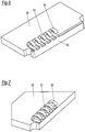
Fig. 5 erkennbar mit drei entlang des Umfangs verteilt angeordneten Schlitzen 18 versehen ist. Von einer Innenwand 19 der Hülse 14 steht eine Rastnase 21 ab, die sich in Umfangsrichtung erstreckt und lediglich durch die Schlitze 18 unterbrochen ist. Weiterhin umfasst das zweite Verbinderteil 16 eine Leiterplatte 22 mit mehreren auf diese aufgebrachten Kontaktelementen 24. Es versteht sich, dass die Anzahl der Kontaktelemente 24 in Abhängigkeit von der Anwendung variieren kann. Vorzugsweise sind die Kontaktelemente 24 auf die Leiterplatte 22 aufgelötet. Insbesondere können die Kontaktelemente 24 mittels SMD-Technik auf die Leiterplatte 22 aufgebracht sein. Die Kontaktelemente 24 sind über die Leiterplatte 22 mit nicht dargestellten Leitungs- und/oder Anschlusselementen des Steckverbinders 11 verbunden. Bei dem inFig. 1 dargestellten Ausführungsbeispiel umfassen die Kontaktelemente 24 federnde Metallzungen und bilden daher Federkontakte. Vorzugsweise ist das zweite Verbinderteil 16 mit Bewegungsspielraum im Sensorgehäuse 17 gelagert, um einen Toleranzausgleich zu ermöglichen. - Wie in
Fig. 1 und2 erkennbar ist, umfasst das erste Verbinderteil 15 einen zumindest im Wesentlichen zylindrischen Grundkörper 25, der in die Hülse 14 des zweiten Verbinderteils 16 einsteckbar ist. An einer Mantelfläche 26 des Grundkörpers 25 befindet sich eine umlaufende Rastnut 27, die mit der Rastnase 21 des zweiten Verbinderteils 16 zusammenwirkt. In dem inFig. 1 dargestellten verbundenen Zustand der Verbinderteile 15, 16 greift die Rastnase 21 in die Rastnut 27 ein. In dem dargestellten verrasteten Zustand ist das erste Verbinderteil 15 um eine Rotationsachse R drehbar an dem zweiten Verbinderteil 16 geführt. - Wie insbesondere aus
Fig. 2 hervorgeht, weist das erste Verbinderteil 15 einen Kabelanschluss 29 auf, der eine gegenüber der Rotationsachse R um etwa 45° geneigte Kabelachse K definiert. Der Kabelanschluss 29 weist einen Kabelkanal 30 sowie mehrere Anschlussstifte 33 auf. Im Bereich des Kabelanschlusses 29 ist ein Außengewinde 34 vorgesehen, auf das eine nicht dargestellte Überwurfmutter aufschraubbar ist. - An einer Vorderseite des Grundkörpers 25 ist ein Anschlusskörper 35 aus einem elektrisch isolierenden Material wie zum Beispiel aus einem faserverstärkten Kunststoff angeordnet. Auf die dem Grundkörper 25 abgewandte Stirnseite 37 des Anschlusskörpers 35 ist eine Anordnung von konzentrischen Leiterbahnen 38 aufgebracht. Wie in
Fig. 3 erkennbar sind die Leiterbahnen 38 teilringförmig und bezüglich der Rotationsachse R konzentrisch. Bei der inFig. 3 gezeigten Ausführungsform erstrecken sie sich über einen Winkelbereich von etwa 270°. Demgegenüber zeigtFig. 4 eine Ausführungsform, bei welcher sich die Leiterbahnen 38 über einen Winkelbereich von 360°, also vollumfänglich, erstrecken. Zusätzlich zu den konzentrischen Leiterbahnen 38 gibt es eine zentrale kreisförmige Leiterfläche 39. Über durch den Anschlusskörper 35 geführte Leitungselemente 40 sind die Leiterbahnen 38 und die Leiterfläche 39 jeweils mit zugehörigen Anschlussstiften 33 elektrisch verbunden. Die Leiterbahnen 38 und die Leiterfläche 39 bilden Kontaktelemente 41 des ersten Verbinderteils 15. - Wenn das erste Verbinderteil 15 wie in
Fig. 1 gezeigt in das zweite Verbinderteil 16 eingesteckt und mit diesem verrastet ist, berühren die Leiterbahnen 38 und die Leiterfläche 39 die federnden Kontaktelemente 24 derart, dass jedes Kontaktelement 41 des ersten Verbinderteils 15 mit genau einem zugehörigen Kontaktelement 24 des zweiten Verbinderteils 16 in elektrischem Kontakt steht. Aufgrund der federnden Wirkung der Kontaktelemente 24 des zweiten Verbinderteils 16 ergibt sich eine bezüglich der Rotationsachse R axiale Kontaktkraft, welche Toleranzen ausgleicht und die Verbindungssicherheit erhöht. - Da das erste Verbinderteil 15 drehbar am zweiten Verbinderteil 16 gelagert ist und die Leiterbahnen 38 bezüglich der Rotationsachse R konzentrisch verlaufen, kann das erste Verbinderteil 15 nach dem Einstecken gedreht werden, ohne die elektrisehe Kontaktierung zu beeinflussen. Dies ist insbesondere deshalb bedeutsam, da das Kabel schräg aus dem Sensorgehäuse herausgeführt ist und somit durch Drehen des ersten Verbinderteils 15 eine Anpassung der Kabelführung an die Einbauverhältnisse möglich ist. Bei der Montage des optoelektronischen Sensors 11 kann somit ein Benutzer zunächst das Sensorgehäuse 17 an einem Trägerbauteil, einer Wand oder dergleichen befestigen, anschließend das erste Verbinderteil 15 in das zweite Verbinderteil 16 einstecken und danach das erste Verbinderteil 15 so zurechtdrehen, dass die schräge Kabelführung im Hinblick auf die Einbaulage besonders günstig ist.
- Wie in
Fig. 6 gezeigt, können die Kontaktelemente 24 des zweiten Verbinderteils 16 beim Aufbringen auf die Leiterplatte 22 durch eine Kontaktleiste 45 zusammengehalten sein, welche zur Verbindung und zur Ausrichtung dient. Nach dem Verlöten der Kontaktelemente 24 wird die Kontaktleiste 45 entfernt, so dass sich der inFig. 7 gezeigte Zustand ergibt. Die Kontaktierung der Leiterbahnen 38 und der Leiterfläche 39 durch die Kontaktelemente 24 ist inFig. 8 veranschaulicht. -
Fig. 9 zeigt einen alternativ gestalteten erfindungsgemäßen Steckverbinder 13', welcher ähnlich gestaltet ist wie der inFig. 1 gezeigte Steckverbinder 13, jedoch einen am ersten Verbinderteil 15 kollinear zur Rotationsachse R angeordneten Zentrierstift 47 aufweist, der in eine passende Zentrieraufnahme 49 der Leiterplatte 22 einführbar ist. Dadurch wird ein Versatz der Verbinderteile 15, 16 quer zur Rotationsachse R weitgehend verhindert. Bei Bedarf kann der Zentrierstift 47 außerdem einen zusätzlichen elektrischen Kontakt bilden. In einem Freiraum 48 zwischen der Leiterplatte 22 und einer Rückwand 50 des zweiten Verbinderteils 16 kann ein Federelement zur axialen Beaufschlagung der Leiterplatte 22 in Richtung des eingesteckten ersten Verbinderteils 15 angeordnet sein. Ein solches Federelement könnte auch bei der inFig. 1 gezeigten Ausführungsform vorgesehen sein. - Die Erfindung ermöglicht einen platzsparenden und flexiblen Anschluss von optoelektronischen Sensoren 11 und anderen Geräten an Steuereinrichtungen, wobei die Möglichkeit einer einfachen Montage sowie einer nachträglichen Korrektur der Kabelführung besteht.
- Bei einer nicht gesondert beschriebenen Ausführungsform befindet sich der Stecker am sensorseitigen Teil des Steckverbinders und die Buchse am kabelseitigen Teil. Es versteht sich, dass einzelne oder mehrere Elemente des Steckverbinders auch an dem jeweils anderen Verbinderteil 15, 16 vorgesehen sein können, als hier explizit beschrieben ist. Z. B. können die konzentrischen Leiterbahnen abweichend von der oben gezeigten Ausführungsform auch an dem sensorseitigen Verbinderteil vorgesehen sein und die komplementären Kontaktelemente am kabelseitigen Teil. Ebenso kann z. B. die Rastverbindung andersherum ausgestaltet sein als oben beschrieben, d. h. die Rastnase kann sich am kabelseitigen Teil des Verbinders befinden und die Rastnut am sensorseitigen Teil.
-
- 11
- optoelektronischer Sensor
- 13, 13'
- Steckverbinder
- 14
- Hülse
- 15
- erstes Verbinderteil
- 16
- zweites Verbinderteil
- 17
- Sensorgehäuse
- 18
- Schlitz
- 19
- Innenwand
- 21
- Rastnase
- 22
- Leiterplatte
- 24
- Kontaktelement
- 25
- Grundkörper
- 26
- Mantelfläche
- 27
- Rastnut
- 29
- Kabelanschluss
- 30
- Kabelkanal
- 33
- Anschlussstift
- 34
- Außengewinde
- 35
- Anschlusskörper
- 37
- Stirnseite
- 38
- Leiterbahn
- 39
- kreisförmige Leiterfläche
- 40
- Leitungselement
- 41
- Kontaktelement
- 45
- Kontaktleiste
- 47
- Zentrierstift
- 48
- Freiraum
- 49
- Zentrieraufnahme
- 50
- Rückwand
- R
- Rotationsachse
- K
- Kabelachse
Claims (15)
- Steckverbinder (13, 13') zum Verbinden einer ein- oder mehradrigen elektrischen Leitung umfassend ein erstes Verbinderteil (15) und ein zweites Verbinderteil (16), die jeweils wenigstens ein Kontaktelement (24, 41) aufweisen und derart miteinander verbindbar sind, dass zumindest ein Kontaktelement (41) des ersten Verbinderteils (15) ein Kontaktelement (24) des zweiten Verbinderteils (16) für einen elektrischen Kontakt berührt, wobei in dem verbundenen Zustand das erste Verbinderteil (15) um eine Rotationsachse (R) drehbar am zweiten Verbinderteil (16) geführt ist und wobei zumindest das wenigstens eine Kontaktelement (41) des ersten Verbinderteils als gekrümmte Leiterbahn (38) ausgeführt ist, deren Krümmungsmittelpunkt zumindest im Wesentlichen mit der Rotationsachse (R) zusammenfällt, wobei das erste Verbinderteil (15) eine quer zu der Rotationsachse (R) verlaufende Kontaktfläche (37) aufweist, auf welche die gekrümmte Leiterbahn (38) aufgebracht ist.
- Steckverbinder nach Anspruch 1,
wobei die Kontaktfläche (37) an einem Anschlusskörper (35) des ersten Verbinderteils (15) ausgebildet ist, der aus einem elektrisch isolierenden Material, insbesondere aus einem faserverstärkten Kunststoff, gefertigt ist. - Steckverbinder nach einem der vorstehenden Ansprüche,
wobei die gekrümmte Leiterbahn (38) einen ringförmigen oder teilringförmigen Verlauf aufweist. - Steckverbinder nach einem der vorstehenden Ansprüche,
wobei sich die gekrümmte Leiterbahn (38) über einen Winkelbereich von wenigstens 90°, bevorzugt von wenigstens 180° und besonders bevorzugt von 360° erstreckt. - Steckverbinder nach einem der vorstehenden Ansprüche,
wobei das erste Verbinderteil (15) und das zweite Verbinderteil (16) jeweils mehrere Kontaktelemente (24, 41) aufweisen, wobei im verbundenen Zustand der Verbinderteile (15, 16) zugehörige Kontaktelemente (24, 41) des ersten Verbinderteils (15) und des zweiten Verbinderteils (16) einander für einen elektrischen Kontakt berühren, und wobei wenigstens zwei der Kontaktelemente (41) des ersten Verbinderteils (15) als konzentrische Leiterbahnen (38) ausgeführt sind. - Steckverbinder nach einem der vorstehenden Ansprüche,
wobei das erste Verbinderteil (15) einen Kabelanschluss (29) aufweist, der eine gegenüber der Rotationsachse (R) geneigte Kabelachse (K) definiert. - Steckverbinder nach einem der vorstehenden Ansprüche,
wobei das erste Verbinderteil (15) mittels eines Verschlusses (21, 27), insbesondere eines Rastverschlusses, am zweiten Verbinderteil (16) arretierbar ist. - Steckverbinder nach einem der vorstehenden Ansprüche,
wobei die Kontaktelemente (24, 41) im verbundenen Zustand der Verbinderteile (15, 16) durch wenigstens ein elastisches Element in axialer Richtung gegeneinander vorgespannt sind. - Steckverbinder nach Anspruch 8,
wobei das wenigstens eine Kontaktelement (24) des zweiten Verbinderteils (16) als Federkontakt ausgeführt ist. - Steckverbinder nach einem der vorstehenden Ansprüche,
wobei das zweite Verbinderteil (16) eine Leiterplatte (22) aufweist und das wenigstens eine Kontaktelement (24) des zweiten Verbinderteils (16) auf die Leiterplatte (22) aufgelötet ist. - Steckverbinder nach einem der vorstehenden Ansprüche,
wobei das erste Verbinderteil (15) einen bezüglich der Rotationsachse (R) rotationssymmetrischen, insbesondere zumindest im Wesentlichen zylindrischen Grundkörper (25) umfasst, der zum Einstecken in eine Aufnahme (14) des zweiten Verbinderteils (16) ausgebildet ist. - Steckverbinder nach Anspruch 11,
wobei an dem Grundkörper (25) eine um die Rotationsachse (R) umlaufende Rastnut (27) vorgesehen ist, die mit einer Rastnase (21) zusammenwirkt, welche an einer Innenwand (19) der Aufnahme (14) angeordnet ist. - Steckverbinder nach einem der vorstehenden Ansprüche,
wobei an dem ersten Verbinderteil (15) ein abstehendes Zentrierelement (47) und an dem zweiten Verbinderteil (16) eine zu dem Zentrierelement (47) passende Zentrieraufnahme (49) angeordnet ist, oder umgekehrt. - Optoelektronischer Sensor (11) mit einem Sensorgehäuse (17) und einem Steckverbinder (13, 13') zum Anschluss eines Kabels an den optoelektronischen Sensor (11),
wobei der Steckverbinder (13, 13') nach wenigstens einem der vorstehenden Ansprüche ausgebildet ist. - Optoelektronischer Sensor nach Anspruch 14,
wobei das zweite Verbinderteil (16) am Sensorgehäuse (17) befestigt, insbesondere in das Sensorgehäuse (17) integriert, ist, wobei das zweite Verbinderteil (16) vorzugsweise mit Bewegungsspielraum im Sensorgehäuse (17) gelagert ist.
Applications Claiming Priority (1)
| Application Number | Priority Date | Filing Date | Title |
|---|---|---|---|
| DE102019112094.2A DE102019112094A1 (de) | 2019-05-09 | 2019-05-09 | Steckverbinder |
Publications (2)
| Publication Number | Publication Date |
|---|---|
| EP3736918A1 true EP3736918A1 (de) | 2020-11-11 |
| EP3736918B1 EP3736918B1 (de) | 2021-09-22 |
Family
ID=70553874
Family Applications (1)
| Application Number | Title | Priority Date | Filing Date |
|---|---|---|---|
| EP20172944.9A Active EP3736918B1 (de) | 2019-05-09 | 2020-05-05 | Steckverbinder und optoelektronischer sensor |
Country Status (2)
| Country | Link |
|---|---|
| EP (1) | EP3736918B1 (de) |
| DE (1) | DE102019112094A1 (de) |
Families Citing this family (2)
| Publication number | Priority date | Publication date | Assignee | Title |
|---|---|---|---|---|
| CN113848422B (zh) * | 2021-09-22 | 2023-04-18 | 中国商用飞机有限责任公司 | 电缆导通测试装置 |
| DE102023201894A1 (de) * | 2023-03-02 | 2024-09-05 | Robert Bosch Gesellschaft mit beschränkter Haftung | Vorrichtung und Verfahren zur elektrischen Kontaktierung eines Sensors |
Citations (3)
| Publication number | Priority date | Publication date | Assignee | Title |
|---|---|---|---|---|
| DE20207165U1 (de) * | 2002-05-07 | 2002-08-14 | Sick AG, 79183 Waldkirch | Kabelanschluss für einen Sensor |
| US20020127891A1 (en) * | 2001-03-08 | 2002-09-12 | Alcatel | Electrical connection device |
| US9829354B2 (en) * | 2014-11-07 | 2017-11-28 | Endress+Hauser Conducta Gmbh+Co. Kg | Sensor arrangement, sensor and cable for use in process automation |
-
2019
- 2019-05-09 DE DE102019112094.2A patent/DE102019112094A1/de not_active Withdrawn
-
2020
- 2020-05-05 EP EP20172944.9A patent/EP3736918B1/de active Active
Patent Citations (3)
| Publication number | Priority date | Publication date | Assignee | Title |
|---|---|---|---|---|
| US20020127891A1 (en) * | 2001-03-08 | 2002-09-12 | Alcatel | Electrical connection device |
| DE20207165U1 (de) * | 2002-05-07 | 2002-08-14 | Sick AG, 79183 Waldkirch | Kabelanschluss für einen Sensor |
| US9829354B2 (en) * | 2014-11-07 | 2017-11-28 | Endress+Hauser Conducta Gmbh+Co. Kg | Sensor arrangement, sensor and cable for use in process automation |
Also Published As
| Publication number | Publication date |
|---|---|
| EP3736918B1 (de) | 2021-09-22 |
| DE102019112094A1 (de) | 2020-11-12 |
Similar Documents
| Publication | Publication Date | Title |
|---|---|---|
| EP3210264B1 (de) | Elektrisches steckverbinderpaar | |
| EP3161908B1 (de) | Kabelanschlussbauteil | |
| EP3613110B1 (de) | Baugruppe für ein steckverbinderteil mit einem kontakteinsatz und einem erdungselement | |
| EP3593413B1 (de) | Rundsteckverbinderbuchse für eine daran anordenbare leiterplatte | |
| EP3203591B1 (de) | Steckverbinder | |
| DE202015009708U1 (de) | Steckverbinder und Stecksystem | |
| EP3736918B1 (de) | Steckverbinder und optoelektronischer sensor | |
| DE102020127203A1 (de) | Steckverbinderanordnung | |
| EP3358682B1 (de) | Elektrischer steckverbinder und elektrisches stecksystem | |
| DE19927198A1 (de) | Lampenfassung aus Isolierstoff | |
| EP3605746A1 (de) | Steckverbinder sowie steckverbindung mit einem solchen steckverbinder | |
| EP2586105B1 (de) | Steckverbinder | |
| EP3496211B1 (de) | Elektrische verbindungsleitung | |
| DE102019210235A1 (de) | Direktsteckverbinder | |
| DE69114888T2 (de) | Zwitterverbinder. | |
| DE202019102604U1 (de) | Steckverbinder | |
| EP3667832A1 (de) | Kontaktträger für ein kontaktelement und kontaktelement | |
| EP1932220B1 (de) | Steckverbindung eines abschlussstecker für antennenanlagen | |
| DE9014856U1 (de) | Isolierkörper für elektrische Kontakte | |
| EP3949024B1 (de) | Steckverbinder | |
| DE19525801C2 (de) | Vorrichtung zum elektrisch leitenden Verbinden von zwei elektrischen Leitungen | |
| EP2339700B1 (de) | Verbinder, Verbinderbuchse und Steckanschluss für ein Hörgerät | |
| EP4371196A1 (de) | Steckverbinder mit wählbarer entriegelung | |
| DE202017107625U1 (de) | Elektrischer Steckverbinder | |
| DE10213990B4 (de) | Elektrische Anschluss- oder Verbindungsklemme |
Legal Events
| Date | Code | Title | Description |
|---|---|---|---|
| PUAI | Public reference made under article 153(3) epc to a published international application that has entered the european phase |
Free format text: ORIGINAL CODE: 0009012 |
|
| STAA | Information on the status of an ep patent application or granted ep patent |
Free format text: STATUS: THE APPLICATION HAS BEEN PUBLISHED |
|
| AK | Designated contracting states |
Kind code of ref document: A1 Designated state(s): AL AT BE BG CH CY CZ DE DK EE ES FI FR GB GR HR HU IE IS IT LI LT LU LV MC MK MT NL NO PL PT RO RS SE SI SK SM TR |
|
| AX | Request for extension of the european patent |
Extension state: BA ME |
|
| STAA | Information on the status of an ep patent application or granted ep patent |
Free format text: STATUS: REQUEST FOR EXAMINATION WAS MADE |
|
| 17P | Request for examination filed |
Effective date: 20201223 |
|
| RBV | Designated contracting states (corrected) |
Designated state(s): AL AT BE BG CH CY CZ DE DK EE ES FI FR GB GR HR HU IE IS IT LI LT LU LV MC MK MT NL NO PL PT RO RS SE SI SK SM TR |
|
| GRAP | Despatch of communication of intention to grant a patent |
Free format text: ORIGINAL CODE: EPIDOSNIGR1 |
|
| STAA | Information on the status of an ep patent application or granted ep patent |
Free format text: STATUS: GRANT OF PATENT IS INTENDED |
|
| RIC1 | Information provided on ipc code assigned before grant |
Ipc: H01R 24/38 20110101ALN20210412BHEP Ipc: H01R 13/627 20060101ALN20210412BHEP Ipc: H01R 12/57 20110101ALN20210412BHEP Ipc: H01R 35/04 20060101AFI20210412BHEP |
|
| INTG | Intention to grant announced |
Effective date: 20210429 |
|
| GRAJ | Information related to disapproval of communication of intention to grant by the applicant or resumption of examination proceedings by the epo deleted |
Free format text: ORIGINAL CODE: EPIDOSDIGR1 |
|
| STAA | Information on the status of an ep patent application or granted ep patent |
Free format text: STATUS: REQUEST FOR EXAMINATION WAS MADE |
|
| GRAJ | Information related to disapproval of communication of intention to grant by the applicant or resumption of examination proceedings by the epo deleted |
Free format text: ORIGINAL CODE: EPIDOSDIGR1 |
|
| STAA | Information on the status of an ep patent application or granted ep patent |
Free format text: STATUS: GRANT OF PATENT IS INTENDED |
|
| INTC | Intention to grant announced (deleted) | ||
| GRAP | Despatch of communication of intention to grant a patent |
Free format text: ORIGINAL CODE: EPIDOSNIGR1 |
|
| RIC1 | Information provided on ipc code assigned before grant |
Ipc: H01R 24/38 20110101ALN20210609BHEP Ipc: H01R 13/627 20060101ALN20210609BHEP Ipc: H01R 12/57 20110101ALN20210609BHEP Ipc: H01R 35/04 20060101AFI20210609BHEP |
|
| RIC1 | Information provided on ipc code assigned before grant |
Ipc: H01R 24/38 20110101ALN20210628BHEP Ipc: H01R 13/627 20060101ALN20210628BHEP Ipc: H01R 12/57 20110101ALN20210628BHEP Ipc: H01R 35/04 20060101AFI20210628BHEP |
|
| INTG | Intention to grant announced |
Effective date: 20210713 |
|
| GRAS | Grant fee paid |
Free format text: ORIGINAL CODE: EPIDOSNIGR3 |
|
| GRAA | (expected) grant |
Free format text: ORIGINAL CODE: 0009210 |
|
| STAA | Information on the status of an ep patent application or granted ep patent |
Free format text: STATUS: THE PATENT HAS BEEN GRANTED |
|
| AK | Designated contracting states |
Kind code of ref document: B1 Designated state(s): AL AT BE BG CH CY CZ DE DK EE ES FI FR GB GR HR HU IE IS IT LI LT LU LV MC MK MT NL NO PL PT RO RS SE SI SK SM TR |
|
| REG | Reference to a national code |
Ref country code: GB Ref legal event code: FG4D Free format text: NOT ENGLISH |
|
| REG | Reference to a national code |
Ref country code: DE Ref legal event code: R096 Ref document number: 502020000202 Country of ref document: DE |
|
| REG | Reference to a national code |
Ref country code: IE Ref legal event code: FG4D Free format text: LANGUAGE OF EP DOCUMENT: GERMAN |
|
| REG | Reference to a national code |
Ref country code: CH Ref legal event code: EP Ref country code: AT Ref legal event code: REF Ref document number: 1433042 Country of ref document: AT Kind code of ref document: T Effective date: 20211015 |
|
| REG | Reference to a national code |
Ref country code: LT Ref legal event code: MG9D |
|
| REG | Reference to a national code |
Ref country code: NL Ref legal event code: MP Effective date: 20210922 |
|
| PG25 | Lapsed in a contracting state [announced via postgrant information from national office to epo] |
Ref country code: RS Free format text: LAPSE BECAUSE OF FAILURE TO SUBMIT A TRANSLATION OF THE DESCRIPTION OR TO PAY THE FEE WITHIN THE PRESCRIBED TIME-LIMIT Effective date: 20210922 Ref country code: SE Free format text: LAPSE BECAUSE OF FAILURE TO SUBMIT A TRANSLATION OF THE DESCRIPTION OR TO PAY THE FEE WITHIN THE PRESCRIBED TIME-LIMIT Effective date: 20210922 Ref country code: LT Free format text: LAPSE BECAUSE OF FAILURE TO SUBMIT A TRANSLATION OF THE DESCRIPTION OR TO PAY THE FEE WITHIN THE PRESCRIBED TIME-LIMIT Effective date: 20210922 Ref country code: BG Free format text: LAPSE BECAUSE OF FAILURE TO SUBMIT A TRANSLATION OF THE DESCRIPTION OR TO PAY THE FEE WITHIN THE PRESCRIBED TIME-LIMIT Effective date: 20211222 Ref country code: NO Free format text: LAPSE BECAUSE OF FAILURE TO SUBMIT A TRANSLATION OF THE DESCRIPTION OR TO PAY THE FEE WITHIN THE PRESCRIBED TIME-LIMIT Effective date: 20211222 Ref country code: HR Free format text: LAPSE BECAUSE OF FAILURE TO SUBMIT A TRANSLATION OF THE DESCRIPTION OR TO PAY THE FEE WITHIN THE PRESCRIBED TIME-LIMIT Effective date: 20210922 Ref country code: FI Free format text: LAPSE BECAUSE OF FAILURE TO SUBMIT A TRANSLATION OF THE DESCRIPTION OR TO PAY THE FEE WITHIN THE PRESCRIBED TIME-LIMIT Effective date: 20210922 |
|
| PG25 | Lapsed in a contracting state [announced via postgrant information from national office to epo] |
Ref country code: LV Free format text: LAPSE BECAUSE OF FAILURE TO SUBMIT A TRANSLATION OF THE DESCRIPTION OR TO PAY THE FEE WITHIN THE PRESCRIBED TIME-LIMIT Effective date: 20210922 Ref country code: GR Free format text: LAPSE BECAUSE OF FAILURE TO SUBMIT A TRANSLATION OF THE DESCRIPTION OR TO PAY THE FEE WITHIN THE PRESCRIBED TIME-LIMIT Effective date: 20211223 |
|
| PG25 | Lapsed in a contracting state [announced via postgrant information from national office to epo] |
Ref country code: IS Free format text: LAPSE BECAUSE OF FAILURE TO SUBMIT A TRANSLATION OF THE DESCRIPTION OR TO PAY THE FEE WITHIN THE PRESCRIBED TIME-LIMIT Effective date: 20220122 Ref country code: SK Free format text: LAPSE BECAUSE OF FAILURE TO SUBMIT A TRANSLATION OF THE DESCRIPTION OR TO PAY THE FEE WITHIN THE PRESCRIBED TIME-LIMIT Effective date: 20210922 Ref country code: RO Free format text: LAPSE BECAUSE OF FAILURE TO SUBMIT A TRANSLATION OF THE DESCRIPTION OR TO PAY THE FEE WITHIN THE PRESCRIBED TIME-LIMIT Effective date: 20210922 Ref country code: PT Free format text: LAPSE BECAUSE OF FAILURE TO SUBMIT A TRANSLATION OF THE DESCRIPTION OR TO PAY THE FEE WITHIN THE PRESCRIBED TIME-LIMIT Effective date: 20220124 Ref country code: PL Free format text: LAPSE BECAUSE OF FAILURE TO SUBMIT A TRANSLATION OF THE DESCRIPTION OR TO PAY THE FEE WITHIN THE PRESCRIBED TIME-LIMIT Effective date: 20210922 Ref country code: NL Free format text: LAPSE BECAUSE OF FAILURE TO SUBMIT A TRANSLATION OF THE DESCRIPTION OR TO PAY THE FEE WITHIN THE PRESCRIBED TIME-LIMIT Effective date: 20210922 Ref country code: ES Free format text: LAPSE BECAUSE OF FAILURE TO SUBMIT A TRANSLATION OF THE DESCRIPTION OR TO PAY THE FEE WITHIN THE PRESCRIBED TIME-LIMIT Effective date: 20210922 Ref country code: EE Free format text: LAPSE BECAUSE OF FAILURE TO SUBMIT A TRANSLATION OF THE DESCRIPTION OR TO PAY THE FEE WITHIN THE PRESCRIBED TIME-LIMIT Effective date: 20210922 Ref country code: CZ Free format text: LAPSE BECAUSE OF FAILURE TO SUBMIT A TRANSLATION OF THE DESCRIPTION OR TO PAY THE FEE WITHIN THE PRESCRIBED TIME-LIMIT Effective date: 20210922 Ref country code: AL Free format text: LAPSE BECAUSE OF FAILURE TO SUBMIT A TRANSLATION OF THE DESCRIPTION OR TO PAY THE FEE WITHIN THE PRESCRIBED TIME-LIMIT Effective date: 20210922 |
|
| REG | Reference to a national code |
Ref country code: DE Ref legal event code: R097 Ref document number: 502020000202 Country of ref document: DE |
|
| PG25 | Lapsed in a contracting state [announced via postgrant information from national office to epo] |
Ref country code: DK Free format text: LAPSE BECAUSE OF FAILURE TO SUBMIT A TRANSLATION OF THE DESCRIPTION OR TO PAY THE FEE WITHIN THE PRESCRIBED TIME-LIMIT Effective date: 20210922 |
|
| PLBE | No opposition filed within time limit |
Free format text: ORIGINAL CODE: 0009261 |
|
| STAA | Information on the status of an ep patent application or granted ep patent |
Free format text: STATUS: NO OPPOSITION FILED WITHIN TIME LIMIT |
|
| 26N | No opposition filed |
Effective date: 20220623 |
|
| PG25 | Lapsed in a contracting state [announced via postgrant information from national office to epo] |
Ref country code: SI Free format text: LAPSE BECAUSE OF FAILURE TO SUBMIT A TRANSLATION OF THE DESCRIPTION OR TO PAY THE FEE WITHIN THE PRESCRIBED TIME-LIMIT Effective date: 20210922 |
|
| REG | Reference to a national code |
Ref country code: BE Ref legal event code: MM Effective date: 20220531 |
|
| PG25 | Lapsed in a contracting state [announced via postgrant information from national office to epo] |
Ref country code: MC Free format text: LAPSE BECAUSE OF FAILURE TO SUBMIT A TRANSLATION OF THE DESCRIPTION OR TO PAY THE FEE WITHIN THE PRESCRIBED TIME-LIMIT Effective date: 20210922 Ref country code: LU Free format text: LAPSE BECAUSE OF NON-PAYMENT OF DUE FEES Effective date: 20220505 |
|
| PG25 | Lapsed in a contracting state [announced via postgrant information from national office to epo] |
Ref country code: IE Free format text: LAPSE BECAUSE OF NON-PAYMENT OF DUE FEES Effective date: 20220505 |
|
| PG25 | Lapsed in a contracting state [announced via postgrant information from national office to epo] |
Ref country code: BE Free format text: LAPSE BECAUSE OF NON-PAYMENT OF DUE FEES Effective date: 20220531 |
|
| REG | Reference to a national code |
Ref country code: CH Ref legal event code: PL |
|
| PG25 | Lapsed in a contracting state [announced via postgrant information from national office to epo] |
Ref country code: LI Free format text: LAPSE BECAUSE OF NON-PAYMENT OF DUE FEES Effective date: 20230531 Ref country code: CH Free format text: LAPSE BECAUSE OF NON-PAYMENT OF DUE FEES Effective date: 20230531 |
|
| PG25 | Lapsed in a contracting state [announced via postgrant information from national office to epo] |
Ref country code: SM Free format text: LAPSE BECAUSE OF FAILURE TO SUBMIT A TRANSLATION OF THE DESCRIPTION OR TO PAY THE FEE WITHIN THE PRESCRIBED TIME-LIMIT Effective date: 20210922 Ref country code: MK Free format text: LAPSE BECAUSE OF FAILURE TO SUBMIT A TRANSLATION OF THE DESCRIPTION OR TO PAY THE FEE WITHIN THE PRESCRIBED TIME-LIMIT Effective date: 20210922 Ref country code: CY Free format text: LAPSE BECAUSE OF FAILURE TO SUBMIT A TRANSLATION OF THE DESCRIPTION OR TO PAY THE FEE WITHIN THE PRESCRIBED TIME-LIMIT Effective date: 20210922 |
|
| PG25 | Lapsed in a contracting state [announced via postgrant information from national office to epo] |
Ref country code: HU Free format text: LAPSE BECAUSE OF FAILURE TO SUBMIT A TRANSLATION OF THE DESCRIPTION OR TO PAY THE FEE WITHIN THE PRESCRIBED TIME-LIMIT; INVALID AB INITIO Effective date: 20200505 |
|
| PG25 | Lapsed in a contracting state [announced via postgrant information from national office to epo] |
Ref country code: TR Free format text: LAPSE BECAUSE OF FAILURE TO SUBMIT A TRANSLATION OF THE DESCRIPTION OR TO PAY THE FEE WITHIN THE PRESCRIBED TIME-LIMIT Effective date: 20210922 |
|
| PG25 | Lapsed in a contracting state [announced via postgrant information from national office to epo] |
Ref country code: MT Free format text: LAPSE BECAUSE OF FAILURE TO SUBMIT A TRANSLATION OF THE DESCRIPTION OR TO PAY THE FEE WITHIN THE PRESCRIBED TIME-LIMIT Effective date: 20210922 |
|
| GBPC | Gb: european patent ceased through non-payment of renewal fee |
Effective date: 20240505 |
|
| PG25 | Lapsed in a contracting state [announced via postgrant information from national office to epo] |
Ref country code: GB Free format text: LAPSE BECAUSE OF NON-PAYMENT OF DUE FEES Effective date: 20240505 |
|
| PGFP | Annual fee paid to national office [announced via postgrant information from national office to epo] |
Ref country code: DE Payment date: 20250519 Year of fee payment: 6 |
|
| PGFP | Annual fee paid to national office [announced via postgrant information from national office to epo] |
Ref country code: IT Payment date: 20250530 Year of fee payment: 6 |
|
| PGFP | Annual fee paid to national office [announced via postgrant information from national office to epo] |
Ref country code: FR Payment date: 20250523 Year of fee payment: 6 |
|
| PGFP | Annual fee paid to national office [announced via postgrant information from national office to epo] |
Ref country code: AT Payment date: 20250519 Year of fee payment: 6 |