EP3736844A1 - Interrupteur électrique à courant continu comportant un pôle limiteur - Google Patents
Interrupteur électrique à courant continu comportant un pôle limiteur Download PDFInfo
- Publication number
- EP3736844A1 EP3736844A1 EP20173112.2A EP20173112A EP3736844A1 EP 3736844 A1 EP3736844 A1 EP 3736844A1 EP 20173112 A EP20173112 A EP 20173112A EP 3736844 A1 EP3736844 A1 EP 3736844A1
- Authority
- EP
- European Patent Office
- Prior art keywords
- contacts
- pole
- switch
- chamber
- electric arc
- Prior art date
- Legal status (The legal status is an assumption and is not a legal conclusion. Google has not performed a legal analysis and makes no representation as to the accuracy of the status listed.)
- Granted
Links
- 238000010891 electric arc Methods 0.000 claims abstract description 21
- 239000004020 conductor Substances 0.000 claims description 4
- 230000015572 biosynthetic process Effects 0.000 claims description 3
- 230000005405 multipole Effects 0.000 abstract description 2
- 238000009434 installation Methods 0.000 description 2
- 239000000696 magnetic material Substances 0.000 description 2
- 238000000034 method Methods 0.000 description 2
- 239000012141 concentrate Substances 0.000 description 1
- 238000010616 electrical installation Methods 0.000 description 1
- 239000002184 metal Substances 0.000 description 1
- 230000010363 phase shift Effects 0.000 description 1
- 238000000926 separation method Methods 0.000 description 1
- 230000001960 triggered effect Effects 0.000 description 1
Images


Classifications
-
- H—ELECTRICITY
- H01—ELECTRIC ELEMENTS
- H01H—ELECTRIC SWITCHES; RELAYS; SELECTORS; EMERGENCY PROTECTIVE DEVICES
- H01H9/00—Details of switching devices, not covered by groups H01H1/00 - H01H7/00
- H01H9/30—Means for extinguishing or preventing arc between current-carrying parts
- H01H9/44—Means for extinguishing or preventing arc between current-carrying parts using blow-out magnet
- H01H9/443—Means for extinguishing or preventing arc between current-carrying parts using blow-out magnet using permanent magnets
-
- H—ELECTRICITY
- H01—ELECTRIC ELEMENTS
- H01H—ELECTRIC SWITCHES; RELAYS; SELECTORS; EMERGENCY PROTECTIVE DEVICES
- H01H33/00—High-tension or heavy-current switches with arc-extinguishing or arc-preventing means
- H01H33/02—Details
- H01H33/59—Circuit arrangements not adapted to a particular application of the switch and not otherwise provided for, e.g. for ensuring operation of the switch at a predetermined point in the ac cycle
- H01H33/596—Circuit arrangements not adapted to a particular application of the switch and not otherwise provided for, e.g. for ensuring operation of the switch at a predetermined point in the ac cycle for interrupting dc
-
- H—ELECTRICITY
- H01—ELECTRIC ELEMENTS
- H01H—ELECTRIC SWITCHES; RELAYS; SELECTORS; EMERGENCY PROTECTIVE DEVICES
- H01H33/00—High-tension or heavy-current switches with arc-extinguishing or arc-preventing means
- H01H33/02—Details
- H01H33/04—Means for extinguishing or preventing arc between current-carrying parts
- H01H33/12—Auxiliary contacts on to which the arc is transferred from the main contacts
- H01H33/121—Load break switches
- H01H33/125—Load break switches comprising a separate circuit breaker
-
- H—ELECTRICITY
- H01—ELECTRIC ELEMENTS
- H01H—ELECTRIC SWITCHES; RELAYS; SELECTORS; EMERGENCY PROTECTIVE DEVICES
- H01H1/00—Contacts
- H01H1/12—Contacts characterised by the manner in which co-operating contacts engage
- H01H1/14—Contacts characterised by the manner in which co-operating contacts engage by abutting
- H01H1/20—Bridging contacts
- H01H1/2041—Rotating bridge
-
- H—ELECTRICITY
- H01—ELECTRIC ELEMENTS
- H01H—ELECTRIC SWITCHES; RELAYS; SELECTORS; EMERGENCY PROTECTIVE DEVICES
- H01H1/00—Contacts
- H01H1/12—Contacts characterised by the manner in which co-operating contacts engage
- H01H1/14—Contacts characterised by the manner in which co-operating contacts engage by abutting
- H01H1/20—Bridging contacts
- H01H1/2066—Fork-shaped bridge; Two transversally connected contact arms bridging two fixed contacts
-
- H—ELECTRICITY
- H01—ELECTRIC ELEMENTS
- H01H—ELECTRIC SWITCHES; RELAYS; SELECTORS; EMERGENCY PROTECTIVE DEVICES
- H01H33/00—High-tension or heavy-current switches with arc-extinguishing or arc-preventing means
- H01H33/02—Details
- H01H33/022—Details particular to three-phase circuit breakers
-
- H—ELECTRICITY
- H01—ELECTRIC ELEMENTS
- H01H—ELECTRIC SWITCHES; RELAYS; SELECTORS; EMERGENCY PROTECTIVE DEVICES
- H01H33/00—High-tension or heavy-current switches with arc-extinguishing or arc-preventing means
- H01H33/02—Details
- H01H33/04—Means for extinguishing or preventing arc between current-carrying parts
- H01H33/08—Stationary parts for restricting or subdividing the arc, e.g. barrier plate
- H01H33/10—Metal parts
-
- H—ELECTRICITY
- H01—ELECTRIC ELEMENTS
- H01H—ELECTRIC SWITCHES; RELAYS; SELECTORS; EMERGENCY PROTECTIVE DEVICES
- H01H33/00—High-tension or heavy-current switches with arc-extinguishing or arc-preventing means
- H01H33/02—Details
- H01H33/04—Means for extinguishing or preventing arc between current-carrying parts
- H01H33/18—Means for extinguishing or preventing arc between current-carrying parts using blow-out magnet
- H01H33/182—Means for extinguishing or preventing arc between current-carrying parts using blow-out magnet using permanent magnets
-
- H—ELECTRICITY
- H01—ELECTRIC ELEMENTS
- H01H—ELECTRIC SWITCHES; RELAYS; SELECTORS; EMERGENCY PROTECTIVE DEVICES
- H01H33/00—High-tension or heavy-current switches with arc-extinguishing or arc-preventing means
- H01H33/02—Details
- H01H33/42—Driving mechanisms
-
- H—ELECTRICITY
- H01—ELECTRIC ELEMENTS
- H01H—ELECTRIC SWITCHES; RELAYS; SELECTORS; EMERGENCY PROTECTIVE DEVICES
- H01H71/00—Details of the protective switches or relays covered by groups H01H73/00 - H01H83/00
- H01H71/10—Operating or release mechanisms
- H01H71/1045—Multiple circuits-breaker, e.g. for the purpose of dividing current or potential drop
-
- H—ELECTRICITY
- H01—ELECTRIC ELEMENTS
- H01H—ELECTRIC SWITCHES; RELAYS; SELECTORS; EMERGENCY PROTECTIVE DEVICES
- H01H77/00—Protective overload circuit-breaking switches operated by excess current and requiring separate action for resetting
- H01H77/02—Protective overload circuit-breaking switches operated by excess current and requiring separate action for resetting in which the excess current itself provides the energy for opening the contacts, and having a separate reset mechanism
- H01H77/10—Protective overload circuit-breaking switches operated by excess current and requiring separate action for resetting in which the excess current itself provides the energy for opening the contacts, and having a separate reset mechanism with electrodynamic opening
- H01H77/107—Protective overload circuit-breaking switches operated by excess current and requiring separate action for resetting in which the excess current itself provides the energy for opening the contacts, and having a separate reset mechanism with electrodynamic opening characterised by the blow-off force generating means, e.g. current loops
- H01H77/108—Protective overload circuit-breaking switches operated by excess current and requiring separate action for resetting in which the excess current itself provides the energy for opening the contacts, and having a separate reset mechanism with electrodynamic opening characterised by the blow-off force generating means, e.g. current loops comprising magnetisable elements, e.g. flux concentrator, linear slot motor
-
- H—ELECTRICITY
- H01—ELECTRIC ELEMENTS
- H01H—ELECTRIC SWITCHES; RELAYS; SELECTORS; EMERGENCY PROTECTIVE DEVICES
- H01H9/00—Details of switching devices, not covered by groups H01H1/00 - H01H7/00
- H01H9/30—Means for extinguishing or preventing arc between current-carrying parts
- H01H9/34—Stationary parts for restricting or subdividing the arc, e.g. barrier plate
- H01H9/346—Details concerning the arc formation chamber
-
- H—ELECTRICITY
- H01—ELECTRIC ELEMENTS
- H01H—ELECTRIC SWITCHES; RELAYS; SELECTORS; EMERGENCY PROTECTIVE DEVICES
- H01H9/00—Details of switching devices, not covered by groups H01H1/00 - H01H7/00
- H01H9/30—Means for extinguishing or preventing arc between current-carrying parts
- H01H9/34—Stationary parts for restricting or subdividing the arc, e.g. barrier plate
- H01H9/36—Metal parts
-
- H—ELECTRICITY
- H01—ELECTRIC ELEMENTS
- H01H—ELECTRIC SWITCHES; RELAYS; SELECTORS; EMERGENCY PROTECTIVE DEVICES
- H01H9/00—Details of switching devices, not covered by groups H01H1/00 - H01H7/00
- H01H9/30—Means for extinguishing or preventing arc between current-carrying parts
- H01H9/40—Multiple main contacts for the purpose of dividing the current through, or potential drop along, the arc
-
- H—ELECTRICITY
- H01—ELECTRIC ELEMENTS
- H01H—ELECTRIC SWITCHES; RELAYS; SELECTORS; EMERGENCY PROTECTIVE DEVICES
- H01H9/00—Details of switching devices, not covered by groups H01H1/00 - H01H7/00
- H01H9/30—Means for extinguishing or preventing arc between current-carrying parts
- H01H9/44—Means for extinguishing or preventing arc between current-carrying parts using blow-out magnet
- H01H9/446—Means for extinguishing or preventing arc between current-carrying parts using blow-out magnet using magnetisable elements associated with the contacts
-
- H—ELECTRICITY
- H01—ELECTRIC ELEMENTS
- H01H—ELECTRIC SWITCHES; RELAYS; SELECTORS; EMERGENCY PROTECTIVE DEVICES
- H01H33/00—High-tension or heavy-current switches with arc-extinguishing or arc-preventing means
- H01H33/02—Details
- H01H33/04—Means for extinguishing or preventing arc between current-carrying parts
- H01H33/12—Auxiliary contacts on to which the arc is transferred from the main contacts
-
- H—ELECTRICITY
- H01—ELECTRIC ELEMENTS
- H01H—ELECTRIC SWITCHES; RELAYS; SELECTORS; EMERGENCY PROTECTIVE DEVICES
- H01H33/00—High-tension or heavy-current switches with arc-extinguishing or arc-preventing means
- H01H33/02—Details
- H01H33/04—Means for extinguishing or preventing arc between current-carrying parts
- H01H33/14—Multiple main contacts for the purpose of dividing the current through, or potential drop along, the arc
-
- H—ELECTRICITY
- H01—ELECTRIC ELEMENTS
- H01H—ELECTRIC SWITCHES; RELAYS; SELECTORS; EMERGENCY PROTECTIVE DEVICES
- H01H33/00—High-tension or heavy-current switches with arc-extinguishing or arc-preventing means
- H01H33/02—Details
- H01H33/04—Means for extinguishing or preventing arc between current-carrying parts
- H01H33/20—Means for extinguishing or preventing arc between current-carrying parts using arcing horns
-
- H—ELECTRICITY
- H01—ELECTRIC ELEMENTS
- H01H—ELECTRIC SWITCHES; RELAYS; SELECTORS; EMERGENCY PROTECTIVE DEVICES
- H01H9/00—Details of switching devices, not covered by groups H01H1/00 - H01H7/00
- H01H9/30—Means for extinguishing or preventing arc between current-carrying parts
- H01H9/38—Auxiliary contacts on to which the arc is transferred from the main contacts
-
- H—ELECTRICITY
- H01—ELECTRIC ELEMENTS
- H01H—ELECTRIC SWITCHES; RELAYS; SELECTORS; EMERGENCY PROTECTIVE DEVICES
- H01H9/00—Details of switching devices, not covered by groups H01H1/00 - H01H7/00
- H01H9/30—Means for extinguishing or preventing arc between current-carrying parts
- H01H9/46—Means for extinguishing or preventing arc between current-carrying parts using arcing horns
Definitions
- the present invention relates to a direct current electric switch comprising a limiting pole.
- high caliber direct current electrical switches for high voltage electrical installations, for example 1500V, high caliber direct current electrical switches (greater than 2000A) are used. This scenario is encountered in particular in photovoltaic installations.
- Electric arc reduction techniques using magnetic circuits, interrupting chambers equipped with separators, spark arrester and arc horns, for example known to EP 3 232 457 allow to control arcs up to certain levels of voltages and currents.
- the known techniques are not sufficiently reliable or do not have sufficient current breaking capacity.
- the invention intends to remedy by proposing a new limiting pole for an electric switch making it possible to cut high voltage and high current lines.
- the invention relates to a high voltage direct current multi-pole electrical switch according to claim 1.
- such a switch can incorporate one or more of the characteristics defined in claims 2 to 9.
- the present invention relates to high caliber direct current switches, for example greater than 2000 A. Such a switch applies in particular to farms or photovoltaic installations of 1500 V.
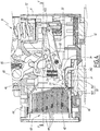
- the figure 1 shows a high voltage direct current multipolar electrical switch 2, comprising a molded case 4 including a main body 6 divided into several interior compartments, in this example four compartments 6A, 6B, 6C and 6D placed side by side along a longitudinal axis X of switch 2.
- Switch 2 has several poles A, B, C and D and each of the compartments 6A, 6B, 6C and 6D is associated with one of the poles A, B, C and D of the switch 2.
- Switch 2 also includes a switching mechanism 8, which is triggered when a current interruption is to be operated, by mechanical, electrical, electronic or other means.
- Switch 2 comprises a limiting pole, formed by pole B, comprising a compartment formed by compartment 6B of the main body 6.
- a compartment 6B In this compartment 6B are provided an input terminal 10 and an output terminal 12 of a current. continuous electric. These terminals 10 and 12 are respectively connected to an electrical distribution network and to an electrical appliance.
- the limiter pole B comprises a first electrical contact 14 connected to the input terminal 10 and a second electrical contact 16 connected to the output terminal 12.
- the contacts 14 and 16 are formed by elongated pieces extending from the terminals 10 and 12.
- the contacts 14 and 16 include contact pads 140 and 160 which form flat surfaces and are placed side by side along the X axis.
- the limiter pole B also comprises a third electrical contact 18 and a fourth electrical contact 20, connected to one another in series. These third and fourth contacts 18 and 20 are respectively movable simultaneously by relative to the first and second electrical contacts 14 and 16, between a closed position and an open position. In the closed position, shown in figure 10 , the first and third contacts 14 and 18 and the second and fourth contacts 16 and 20 are respectively in contact with each other to allow the flow of direct electric current between the terminals 10 and 12. On the figure 10 , only the contact between contacts 14 and 18 is visible, contacts 16 and 20 being hidden. In the open position, shown in figures 3 , 4 , 7 and 8 , the contacts are distant from each other, interrupting the flow of current between terminals 10 and 12. The contacts can be separated by the switching mechanism 8.
- the third and fourth contacts 18 and 20 are provided on a movable part 22 actuated by the switching mechanism 8.
- the movable part 22 is movable in rotation about an axis of rotation X22 parallel to the longitudinal axis X.
- Each of the contacts 18 and 20 is carried by a respective pair of fingers 24 and 26 secured to the moving part 22.
- the contacts 18 and 20 are provided in the form of contact pads attached to the pairs of fingers 24 and 26.
- the pairs of fingers 24 and 26 are movable in rotation relative to the movable part 22 about an axis X24, and are pushed back towards the contacts 14 and 16 by springs 28, in order to maximize the contact force in the closed position.
- the mobile part 22 comprises an electrical connection element between the third and fourth contacts 18 and 20 allowing their electrical connection in series.
- This contact element may be an axis 30, provided in conductive material, common to the pairs of fingers 24 and 26 and passing through the movable part 22, aligned with the axis X24 and making it possible to support the pairs of fingers 24 and 26 in their freedom. in rotation relative to the moving part 22.
- the series connection of the contacts 18 and 20 is then effected by conduction through the axis 30.
- connection can be made with conductive elements, such as conductive braids 32 and 34 extending between the pairs of fingers 24 and 26 and a not shown conductive axis supporting the rotation of the movable part 22 around the axis X22.
- conductive elements such as conductive braids 32 and 34 extending between the pairs of fingers 24 and 26 and a not shown conductive axis supporting the rotation of the movable part 22 around the axis X22.
- the series connection between the contacts 18 and 20 is made via the conductive braids 32 and 34 and the aligned conductor axis carrying the X22 axis.
- the limiting pole B comprises a first chamber 36 for forming an electric arc, in which the first electric contact 14 and the third are placed. electric contact 18.
- the limiting pole B comprises a second chamber 38 for forming an electric arc, in which the second electric contact 16 and the fourth electric contact 20 are placed.
- the chambers 36 and 38 are the place where electric arcs are formed. that occur when opening contacts.
- the chambers 36 and 38 are separated in the direction of the X axis by a central wall 60 of the main body 6 which extends perpendicular to the X axis at the center of the compartment 6B.
- the limiting pole B also comprises a first interrupting chamber 40 and a second interrupting chamber 42, respectively associated with the first chamber 36 and with the second chamber 38 forming a electric arc.
- the interrupting chamber 40 is contiguous to the chamber 36, and these two chambers 36 and 40 form a single space delimited along the X axis by the central wall 60 and by a wall 62 of the main body 6 which separates the compartment 6B from the compartment 6C.
- the interrupting chamber 42 is contiguous to the chamber 38, and these two chambers 38 and 42 form a single space delimited along the X axis by the central wall 60 and by a wall 64 of the main body 6 which separates the compartment 6B from the compartment 6A.
- the first and second arcing chambers 36 and 38 are placed side by side along the X axis.
- Each of the first and second interrupting chambers 40 and 42 comprises separators 44 formed by parallel metal plates stepped in planes parallel to the X axis. These separators 44, which may be 30 in number, are staggered over a height of the axis. compartment 6B between a bottom 66, in the vicinity of which the terminal 10 is located, and an upper wall 68.
- the dividers 44 have central notches 440 delimiting two parts located on either side of a median plane P44, perpendicular to the 'axis X, which is also a median plane of each interrupting chamber 40 and 42.
- each separator 44 has protuberances 442 directed towards the formation chambers 36 and 38 of the electric arcs and which partially protrude in these chambers, and provided on either side of the median planes P44 of each interrupting chamber 40 and 42.
- These protuberances make it possible to capture low current electric arcs, in particular between 10 A and 100 A, which do not are not directed along the axis of the interrupting chambers 40 and 42 by an electromagnetic force as is the case with high current electric arcs (greater than 100A, up to 40000A).
- Each of the interrupting chambers 40 and 42 comprises a spark arrester 46 extending between the separator 44 placed at the top of the stack and the wall. upper 68 and moving in an oblique direction towards the associated arcing chamber 36 or 38. These spark arresters aim to direct the electric arcs towards the separators 44.
- Each of the interrupting chambers 40 and 42 also includes an arc horn 48 extending between the bottom 66 and the lowest separator 44 of the stack, and leading towards the respective contact 14 or 16 placed in the chamber. formation 36 or 38 associated with the interrupting chamber 40 or 42.
- the arc horns 48 also aim to direct the electric arcs towards the separators 44.
- Each of the first and second arcing chambers 36 and 38 comprises a magnetic circuit including a magnet and generating a magnetic field which is configured to guide towards the interrupting chamber 40 or 42 associated with this arcing chamber.
- the chamber 36 for forming an electric arc comprises a circuit magnetic 50, comprising a magnet 500, placed under the contact 14, and a frame 502 of magnetic material in the shape of a "U" also placed under the contact 14 and contiguous to the magnet 500, and whose branches extend into the chamber 36 on either side of the pair of fingers 24.
- a magnetic field generated by the magnet 500 and guided by the armature 502 attracts the low current arcs towards the interrupting chamber 40.
- the forming chamber 38 comprises a magnetic circuit 52, comprising a magnet 520, placed under the contact 16, and an armature 522 of magnetic material in the form of a "U" also placed under the contact 16 and contiguous to the magnet 520, and whose branches extend into chamber 38 on either side of pair of fingers 26.
- a magnetic field generated by magnet 520 and guided by armature 522 attracts low current arcs towards the interrupting chamber 42.
- the structure of the limiting pole B makes it possible to cut the current at two points in series, which makes it possible to divide the electric arcs linked to the interruption of the current and to treat them separately, in two separate interrupting chambers.
- the voltage that can be cut is greater than for conventional limiter poles having only one cut-off chamber.
- the two “arc-forming chamber / breaking chamber” pairs of the limiter pole B make it possible to cut up, for example, 750 V per couple, i.e. a total of 1500 V, in particular for photovoltaic farms generating such a voltage.
- Switch 2 further comprises at least one conductive pole.
- the switch 2 has three conducting poles formed by the poles A, C and D. Only the conducting pole A will be described in what follows, the conducting poles C and D having a structure identical to that of the conducting pole A .
- the conductive pole A is provided with an input terminal 54 and an output terminal 56.
- the conductive poles C and D also each include an input terminal 54.
- the input terminals 54 of the conductive poles A, C and D and the input terminal 10 of the limiter pole B are connected to each other by an equipotential bar 76.
- This equipotential bar 76 is an element made of a conductive material inserted in holes of the three input terminals 54 and of the input terminal 10 and making it possible to avoid the differences in electric potential between these elements.
- the conductive pole A also comprises a first series of electrical contacts 58 connected to the input terminal 54, and a second series of electrical contacts 70 connected to the output terminal 56.
- the first and second series of electrical contacts 58 and 70 are separable by the switching mechanism 8, as can be seen at figure 9 in an open configuration of contacts.
- the switching mechanism 8 is configured to separate the contacts of the conductive poles A, C and D before the contacts of the limiting pole B.
- the poles A, B, C and D are connected in a parallel arrangement.
- the desired goal is to concentrate the phenomena of electric arcs in the limiting pole B.
- the second series of electrical contacts 70 of the conductive pole A comprises at least ten contacts each carried by a finger 72 integral with a movable part 74 actuated by the switching mechanism 8.
- the movable part 74 is movable in rotation about an axis X74 parallel to the X axis. In the closed configuration of contacts 58 and 70, current flows from contacts 70 to output terminal 56 via fingers 72 and moving part 74.
- the switching mechanism 8 comprises an actuating shaft 80 on which are provided rotary arms 82, each of these rotary arms 82 being associated with one of the poles A, B, C and D and whose role is to actuate the opening of the contacts of this pole.
- the rotation of the actuating shaft 80 causes the simultaneous rotation of the rotary arms 82.
- the rotary arms 82 are connected to the moving parts 22 and 74 by means of connecting rods.
- the switching mechanism 8 comprises a first link 84 connecting one of the rotary arms 82 to the first movable part 22, and at least a second link 86 connecting another rotary arm 82 to the second movable part 74.
- a length L2 of the first connecting rod 84 is greater than a length L1 of the second connecting rod 86. This allows that, during the instant immediately following the opening of the contacts of the conductive pole A ( figure 9 ), for the same angle of rotation of the shaft 80, the contacts of the limiting pole B are always held against each other ( figure 10 ).
- a phase shift of the openings is therefore obtained, which may for example be 5 °, by mechanical means, that is to say not involving electronic control or other artifice.
- the reliability of switch 2 is thereby improved.
- Switch 2 shown in figure 2 is a unipolar switch-disconnector, for example with a nominal current of 10000A (thanks to the three conducting poles A, C and D with ten fingers in parallel), having a breaking capacity which can be for example 20 kA at a voltage of 1500V (by the limiter pole B).
- the switch 2 may comprise a number of conductive poles other than three, in particular one or two conductive poles.
Landscapes
- Engineering & Computer Science (AREA)
- Power Engineering (AREA)
- Physics & Mathematics (AREA)
- Electromagnetism (AREA)
- Arc-Extinguishing Devices That Are Switches (AREA)
Abstract
Description
- La présente invention concerne un interrupteur électrique à courant continu comportant un pôle limiteur.
- Pour des installations électriques de voltage important, par exemple 1500V, des interrupteurs électriques à courant continu à fort calibre (supérieur à 2000A) sont utilisés. Ce cas de figure se rencontre notamment dans les installations photovoltaïques.
- Les techniques de réduction des arcs électriques, utilisant des circuits magnétiques, des chambres de coupure munies de séparateurs, de pare-étincelle et de cornes d'arcs, par exemple connues de
EP 3 232 457 permettent de contrôler les arcs jusqu'à certains niveaux de voltages et courants. Toutefois, pour les applications mentionnées ci-dessus, les techniques connues ne sont pas suffisamment fiables ou n'ont pas une capacité de coupure de courant suffisante. - C'est à ces inconvénients qu'entend remédier l'invention en proposant un nouveau pôle limiteur d'interrupteur électrique permettant de couper des lignes à forte tension et à fort courant.
- L'invention concerne un interrupteur électrique multipolaire à courant continu haute tension selon la revendication 1.
- Selon des aspects avantageux mais non obligatoires de l'invention, un tel interrupteur peut incorporer une ou plusieurs des caractéristiques définies dans les revendications 2 à 9.
- L'invention sera mieux comprise et d'autres avantages de celle-ci apparaîtront plus clairement à la lumière de la description qui va suivre d'un pôle d'interrupteur et d'un interrupteur conformes à son principe, faite à titre d'exemple non limitatif et en référence aux dessins annexés dans lesquels :
- [
Fig 1 ] lafigure 1 est une vue en perspective d'un interrupteur conforme à l'invention ; - [
Fig 2 ] lafigure 2 est une coupe longitudinale de l'interrupteur de lafigure 1 ; - [
Fig 3 ] lafigure 3 est une coupe selon le plan III-III à lafigure 2 , d'un pôle limiteur de l'interrupteur de lafigure 1 ; - [
Fig 4 ] lafigure 4 est une coupe selon le plan IV-IV à lafigure 2 , du pôle limiteur de lafigure 3 ; - [
Fig 5 ] lafigure 5 est une coupe de l'interrupteur de lafigure 1 selon le plan V-V à lafigure 4 ; - [
Fig 6 ] lafigure 6 est une vue à plus grande échelle du détail VI à lafigure 5 ; - [
Fig 7 ] lafigure 7 est une vue en perspective de l'interrupteur de lafigure 1 coupée selon le plan III-III; - [
Fig 8 ] lafigure 8 est une vue en perspective de l'interrupteur de lafigure 1 coupée selon le plan IV-IV; - [
Fig 9 ] lafigure 9 est une coupe d'un pôle conducteur de l'interrupteur de lafigure 1 selon le plan IX-IX à lafigure 2 ; - [
Fig 10 ] lafigure 10 est une coupe du pôle limiteur selon le plan X-X à lafigure 2 . - La présente invention concerne les interrupteurs en courant continu de fort calibre, par exemple supérieur à 2000 A. Un tel interrupteur s'applique notamment aux fermes ou installations photovoltaïques de 1500 V.
- La
figure 1 représente un interrupteur électrique multipolaire 2 à courant continu haute tension, comportant un boitier moulé 4 incluant un corps principal 6 divisé en plusieurs compartiments intérieurs, dans cet exemple quatre compartiments 6A, 6B, 6C et 6D placés côte-à-côte selon un axe longitudinal X de l'interrupteur 2. L'interrupteur 2 comporte plusieurs pôles A, B, C et D et chacun des compartiments 6A, 6B, 6C et 6D est associé à l'un des pôles A, B, C et D de l'interrupteur 2. - L'interrupteur 2 comporte également un mécanisme de commutation 8, qui est déclenché lors qu'une interruption de courant doit être opérée, par des moyens mécaniques, électriques, électroniques, ou autres.
- L'interrupteur 2 comporte un pôle limiteur, formé par le pôle B, comprenant un compartiment formé par le compartiment 6B du corps principal 6. Dans ce compartiment 6B sont prévus un terminal d'entrée 10 et un terminal de sortie 12 d'un courant électrique continu. Ces terminaux 10 et 12 sont respectivement reliés à un réseau électrique de distribution et à un appareil électrique.
- Le pôle limiteur B comprend un premier contact électrique 14 relié au terminal d'entrée 10 et un deuxième contact électrique 16 relié au terminal de sortie 12. Les contacts 14 et 16 sont formés par des pièces allongées s'étendant à partir des terminaux 10 et 12. Les contacts 14 et 16 comportent des pastilles de contact 140 et 160 qui forment des surfaces planes et sont placées côte-à-côte selon l'axe X.
- Le pôle limiteur B comprend également un troisième contact électrique 18 et un quatrième contact électrique 20, reliés l'un à l'autre en série. Ces troisième et quatrième contacts 18 et 20 sont respectivement déplaçables simultanément par rapport aux premier et deuxième contacts électriques 14 et 16, entre une position fermée et une position ouverte. Dans la position fermée, représentée à la
figure 10 , les premiers et troisièmes contacts 14 et 18 et les deuxièmes et quatrième contacts 16 et 20 sont respectivement en contact les uns avec les autres pour autoriser la circulation du courant électrique continu entre les terminaux 10 et 12. Sur lafigure 10 , uniquement le contact entre les contacts 14 et 18 est visible, les contacts 16 et 20 étant masqués. Dans la position ouverte, représentée auxfigures 3 ,4 ,7 et8 , les contacts sont distants les uns des autres, interrompant le passage du courant entre les terminaux 10 et 12. Les contacts sont séparables par le mécanisme de commutation 8. - Les troisième et quatrième contacts 18 et 20 sont prévus sur une pièce mobile 22 actionnée par le mécanisme de commutation 8. La pièce mobile 22 est mobile en rotation autour d'un axe de rotation X22 parallèle à l'axe longitudinal X.
- Chacun des contacts 18 et 20 est porté par une paire de doigts respective 24 et 26 solidaire de la pièce mobile 22. Les contacts 18 et 20 sont prévus sous la forme de pastilles de contact fixées aux paires de doigts 24 et 26. Les paires de doigts 24 et 26 sont mobiles en rotation par rapport à la pièce mobile 22 autour d'un axe X24, et sont repoussés en direction des contacts 14 et 16 par des ressorts 28, afin de maximiser la force de contact en position fermée.
- La pièce mobile 22 comporte un élément de liaison électrique entre les troisième et quatrième contacts 18 et 20 permettant leur liaison électrique en série. Cet élément de contact peut être un axe 30, prévu en matériau conducteur, commun aux paires de doigts 24 et 26 et traversant la pièce mobile 22, aligné avec l'axe X24 et permettant de supporter les paires de doigts 24 et 26 dans leur liberté en rotation par rapport à la pièce mobile 22. La liaison en série des contacts 18 et 20 se fait alors par conduction à travers l'axe 30.
- En variante, la liaison peut être effectuée avec des éléments conducteurs, tel que des tresses conductrices 32 et 34 s'étendant entre les paires de doigts 24 et 26 et un axe conducteur non représenté supportant la rotation de la pièce mobile 22 autour de l'axe X22. Dans un tel cas, la liaison en série entre les contacts 18 et 20 se fait via les tresses conductrices 32 et 34 et l'axe conducteur aligné portant l'axe X22.
- Lorsque les contacts sont fermés, le courant passe, selon les flèches F1 aux
figures 7 et8 , du terminal 10 au contact 14, puis au contact 18, puis au contact 20 via l'axe 30 ou les tresses 32 et 34, puis au contact 16, et enfin au terminal 12. - Le pôle limiteur B comprend une première chambre 36 de formation d'un arc électrique, dans laquelle sont placés le premier contact électrique 14 et le troisième contact électrique 18. Le pôle limiteur B comprend une seconde chambre 38 de formation d'un arc électrique, dans laquelle sont placés le deuxième contact électrique 16 et le quatrième contact électrique 20. Les chambres 36 et 38 sont le lieu de formation des arcs électriques qui surviennent lors de l'ouverture des contacts. Les chambres 36 et 38 sont séparées dans le sens de l'axe X par une paroi 60 central du corps principal 6 qui s'étend perpendiculairement à l'axe X au centre du compartiment 6B.
- Pour couper les arcs électriques issus de la séparation des contacts, le pôle limiteur B comprend également une première chambre de coupure 40 et une seconde chambre de coupure 42, respectivement associées à la première chambre 36 et à la seconde chambre 38 de formation d'un arc électrique. La chambre de coupure 40 est contiguë à la chambre 36, et ces deux chambres 36 et 40 forment un seul espace délimité selon l'axe X par la paroi centrale 60 et par une paroi 62 du corps principal 6 qui sépare le compartiment 6B du compartiment 6C. De l'autre côté de la paroi centrale 60, la chambre de coupure 42 est contiguë à la chambre 38, et ces deux chambres 38 et 42 forment un seul espace délimité selon l'axe X par la paroi centrale 60 et par une paroi 64 du corps principal 6 qui sépare le compartiment 6B du compartiment 6A. Les première et seconde chambres de formation d'un arc électrique 36 et 38 sont placées côte à côte le long de l'axe X.
- Chacune des première et seconde chambres de coupure 40 et 42 comprend des séparateurs 44 formés par des plaques métalliques parallèles étagées selon des plans parallèles à l'axe X. Ces séparateurs 44, pouvant être au nombre de 30, s'étagent sur une hauteur du compartiment 6B entre un fond 66, au voisinage duquel se trouve le terminal 10, et une paroi supérieure 68. Les séparateurs 44 présentent des entailles centrales 440 délimitant deux parties localisées de part et d'autre d'un plan médian P44, perpendiculaire à l'axe X, qui est également un plan médian de chaque chambre de coupure 40 et 42. Avantageusement, chaque séparateur 44 présente des protubérances 442 dirigées vers les chambres de formation 36 et 38 des arcs électriques et qui font partiellement saillie dans ces chambres, et prévues de part et d'autre des plans médians P44 de chaque chambre de coupure 40 et 42. Ces protubérances permettent de capter des arcs électriques de courant faible, notamment entre 10 A et 100 A, qui ne sont pas dirigés dans l'axe des chambres de coupure 40 et 42 par une force électromagnétique comme c'est le cas des arcs électriques de fort courant (supérieur à 100A, jusqu'à 40000A).
- Chacune des chambres de coupure 40 et 42 comporte un pare-étincelle 46 s'étendant entre le séparateur 44 placé au sommet de l'empilement et la paroi supérieure 68 et se dirigeant selon une direction oblique vers la chambre de formation d'arc associée 36 ou 38. Ces pare-étincelle visent à diriger les arcs électriques vers les séparateurs 44.
- Chacune des chambres de coupure 40 et 42 comporte également une corne d'arc 48 s'étendant entre le fond 66 et le séparateur 44 le plus bas de l'empilement, et se dirigeant vers le contact respectif 14 ou 16 placé dans la chambre de formation 36 ou 38 associée à la chambre de coupure 40 ou 42. Les cornes d'arc 48 visent également à diriger les arcs électriques vers les séparateurs 44.
- Chacune des première et seconde chambres 36 et 38 de formation des arcs électriques comprend un circuit magnétique incluant un aimant et générant un champ magnétique qui est configuré pour guider, en direction de la chambre de coupure 40 ou 42 associée à cette chambre de formation d'un arc électrique 36 ou 38, un arc électrique se formant dans la position ouverte entre les contacts prévus dans cette chambre de formation d'un arc électrique 36 ou 38. Plus précisément, la chambre 36 de formation d'un arc électrique comporte un circuit magnétique 50, comprenant un aimant 500, placé sous le contact 14, et une armature 502 en matériau magnétique en forme de « U » placée également sous le contact 14 et accolée à l'aimant 500, et dont les branches s'étendent dans la chambre 36 de part et d'autre de la paire de doigts 24. Un champ magnétique généré par l'aimant 500 et guidé par l'armature 502 attire les arcs de faible courant vers la chambre de coupure 40.
- De façon similaire, la chambre de formation 38 comporte un circuit magnétique 52, comprenant un aimant 520, placé sous le contact 16, et une armature 522 en matériau magnétique en forme de « U » placée également sous le contact 16 et accolée à l'aimant 520, et dont les branches s'étendent dans la chambre 38 de part et d'autre de la paire de doigts 26. Un champ magnétique généré par l'aimant 520 et guidé par l'armature 522 attire les arcs de faible courant vers la chambre de coupure 42.
- La structure du pôle limiteur B permet de couper le courant en deux points en série, ce qui permet de diviser les arcs électriques liés à l'interruption du courant et de les traiter séparément, dans deux chambres de coupure distinctes. Il en résulte que le voltage pouvant être coupé est plus important que pour les pôles limiteurs classiques ne comportant qu'une seule chambre de coupure. Dans le cas présent, les deux couples « chambre de formation d'arc / chambre de coupure » du pôle limiteur B permettent de couper jusqu'à par exemple 750 V par couple, soit un total de 1500 V, notamment pour les fermes photovoltaïques générant un tel voltage.
- L'interrupteur 2 comporte en outre au moins un pôle conducteur. Dans cet exemple, l'interrupteur 2 comporte trois pôles conducteurs formés par les pôles A, C et D. Seul le pôle conducteur A sera décrit dans ce qui suit, les pôles conducteurs C et D présentant une structure identique à celle du pôle conducteur A.
- Le pôle conducteur A est muni d'un terminal d'entrée 54 et d'un terminal de sortie 56. Les pôles conducteurs C et D comprennent également chacun un terminal d'entrée 54. Comme cela est visible à la
figure 2 , les terminaux d'entrée 54 des pôles conducteurs A, C et D et le terminal d'entrée 10 du pôle limiteur B sont reliés les uns aux autres par une barre équipotentielle 76. Cette barre équipotentielle 76 est un élément en matériau conducteur inséré dans des trous des trois terminaux d'entrée 54 et du terminal d'entrée 10 et permettant d'éviter les différences de potentiel électrique entre ces éléments. - Le pôle conducteur A comprend également une première série de contacts électriques 58 reliés au terminal d'entrée 54, et une seconde série de contacts électriques 70 reliés au terminal de sortie 56. Les première et seconde séries de contacts électriques 58 et 70 sont séparables par le mécanisme de commutation 8, comme cela est visible à la
figure 9 dans une configuration ouverte des contacts. - Le mécanisme de commutation 8 est configuré pour séparer les contacts des pôles conducteurs A, C et D avant les contacts du pôle limiteur B. Les pôles A, B, C et D sont connectés selon une disposition en parallèle. Le but recherché est de concentrer les phénomènes d'arcs électriques dans le pôle limiteur B.
- La seconde série de contacts électriques 70 du pôle conducteur A comporte au moins dix contacts portés chacun par un doigt 72 solidaire d'une pièce mobile 74 actionnée par le mécanisme de commutation 8. La pièce mobile 74 est mobile en rotation autour d'un axe X74 parallèle à l'axe X. En configuration fermée des contacts 58 et 70, le courant passe des contacts 70 vers le terminal de sortie 56 via les doigts 72 et la pièce mobile 74.
- Le mécanisme de commutation 8 comporte un arbre d'actionnement 80 sur lequel sont prévus des bras rotatifs 82, chacun de ces bras rotatifs 82 étant associé à l'un des pôles A, B, C et D et dont le rôle est d'actionner l'ouverture des contacts de ce pôle. La rotation de l'arbre d'actionnement 80 occasionne la rotation simultanée des bras rotatifs 82. Les bras rotatifs 82 sont reliés aux pièces mobiles 22 et 74 par l'intermédiaire de bielles. Le mécanisme de commutation 8 comprend une première bielle 84 reliant l'un des bras rotatifs 82 à la première pièce mobile 22, et au moins une seconde bielle 86 reliant un autre bras rotatif 82 à la seconde pièce mobile 74. Pour obtenir l'ouverture du pôle conducteur A avant le pôle limiteur B, une longueur L2 de la première bielle 84 est supérieure à une longueur L1 de la seconde bielle 86. Ceci permet que, lors de l'instant immédiatement consécutif à l'ouverture des contacts du pôle conducteur A (
figure 9 ), pour un même angle de rotation de l'arbre 80, les contacts du pôle limiteur B sont toujours maintenus les uns contre les autres (figure 10 ). - On obtient donc un déphasage des ouvertures, pouvant par exemple être de 5°, par des moyens mécaniques, c'est-à-dire ne faisant pas intervenir de contrôle électronique ou autre artifice. La fiabilité de l'interrupteur 2 en est améliorée.
- L'interrupteur 2 représenté à la
figure 2 est un interrupteur sectionneur unipolaire, par exemple de courant nominal 10000A (grâce aux trois pôles conducteurs A, C et D à dix doigts en parallèle), ayant une capacité de coupure pouvant être par exemple de 20 kA à une tension de 1500V (par le pôle limiteur B). - Selon un mode de réalisation non représenté, l'interrupteur 2 peut comprendre un nombre de pôles conducteurs différent de trois, notamment un ou deux pôles conducteurs.
Claims (9)
- Interrupteur électrique multipolaire à courant continu haute tension (2), comportant un boitier moulé (4) incluant un corps principal (6) divisé en plusieurs compartiments intérieurs (6A, 6B, 6C, 6D) chacun associé à un pôle (A, B, C, D) de l'interrupteur (2), et un mécanisme de commutation (8), caractérisé en ce que l'un des pôles de l'interrupteur (2) est formé par un pôle limiteur (B) comprenant un compartiment (6B) formé par l'un des compartiments intérieurs (6A, 6B, 6C, 6D) du corps principal (6), dans ce compartiment (6B) étant prévus un terminal d'entrée (10) et un terminal de sortie (12) d'un courant électrique continu, le pôle limiteur (B) comprenant un premier contact électrique (14) relié au terminal d'entrée (10) et un deuxième contact électrique (16) relié au terminal de sortie (12), un troisième (18) et un quatrième (20) contacts électriques reliés l'un à l'autre en série, les troisième et quatrième contacts (18, 20) étant respectivement déplaçables simultanément par rapport aux premier et deuxième contacts électriques (14, 16), entre une position fermée, dans laquelle les premiers (14) et troisièmes contacts (18) et les deuxième (16) et quatrième contacts (20) sont en contact les uns avec les autres pour autoriser la circulation du courant électrique continu entre le terminal d'entrée (10) et le terminal de sortie (12), et une position ouverte, dans laquelle lesdits contacts sont distants les uns des autres interrompant la circulation du courant entre le terminal d'entrée (10) et le terminal de sortie (12), en ce que le pôle limiteur (B) comprend une première chambre de formation (36) d'un arc électrique dans laquelle sont placés le premier (14) et le troisième (18) contacts électriques, une seconde chambre de formation (38) d'un arc électrique dans laquelle sont placés le deuxième (16) et le quatrième (20) contacts électriques, et une première (40) et une seconde (42) chambres de coupure d'un arc électrique, respectivement associées aux première (36) et seconde chambre (38) de formation d'un arc électrique, les contacts (14, 18, 16, 20) du pôle limiteur (B) étant séparables par le mécanisme de commutation (8), en ce que l'interrupteur comprend au moins un pôle conducteur (A, C, D) muni d'un terminal d'entrée (54) et d'un terminal de sortie (56), d'une première série de contacts électriques (58) reliés au terminal d'entrée (54) et d'une seconde série de contacts électriques (70) reliés au terminal de sortie (56), les première et secondes séries de contacts électriques (58, 70) étant séparables par le mécanisme de commutation, et en ce que le mécanisme de commutation (8) est configuré pour séparer les contacts (58, 70) du ou des pôles conducteurs (A, C, D) avant les contacts (14, 18, 16, 20) du pôle limiteur (B).
- Interrupteur selon la revendication 1, caractérisé en ce que les troisième (18) et quatrième (20) contacts du pôle limiteur (B) sont prévus sur une première pièce mobile (22), en ce que la seconde série de contacts (70) du pôle conducteur (A, C, D) est prévue sur une seconde pièce mobile (74), en ce le mécanisme de commutation (8) comporte : un arbre d'actionnement (80) sur lequel sont prévus des bras rotatifs (82), une première bielle (84) reliant l'un des bras rotatifs (82) à la première pièce mobile (22), et au moins une seconde bielle (86) reliant l'un des bras rotatifs (82) à la seconde pièce mobile (74), et en ce que la longueur (L2) de la première bielle (84) est supérieure à la longueur (L1) de la seconde bielle (86).
- Interrupteur selon l'une des revendications précédentes, caractérisé en ce que la seconde série de contacts électriques (70) du pôle conducteur (A, C, D) comporte au moins dix contacts portés chacun par un doigt (72) solidaire d'une pièce mobile (74) de ce pôle conducteur (A, C, D) actionnée par le mécanisme de commutation (8).
- Interrupteur selon l'une des revendications précédentes, caractérisé en ce qu'il comporte trois pôles conducteurs (A, C, D).
- Interrupteur selon l'une des revendications précédentes, caractérisé en ce que les première et seconde chambres de coupure (40, 42) comprennent des séparateurs (44) présentant des protubérances (442) dirigées vers les chambres de formation d'un arc électrique (36, 38) et prévues de part et d'autre d'un plan médian (P44) de chaque chambre de coupure (40, 42).
- Interrupteur selon l'une des revendications précédentes, caractérisé en ce que les troisième (18) et quatrième (20) contacts sont prévus sur une première pièce mobile (22) actionnée par un mécanisme de commutation (8) de l'interrupteur (2), et en ce que la première pièce mobile (22) comporte un élément de liaison électrique (30 ; 32, 34) entre les troisième (18) et quatrième (20) contacts.
- Interrupteur selon l'une des revendications précédentes, caractérisé en ce que chacune des première (36) et seconde (38) chambres de formation d'un arc électrique comprend un circuit magnétique (50, 52) incluant un aimant (500, 520) et générant un champ magnétique qui est configuré pour guider, en direction de la chambre de coupure (40, 42) associée à cette chambre de formation d'un arc électrique (36, 38), un arc électrique se formant dans la position ouverte entre les contacts (14, 18, 16, 20) prévus dans cette chambre de formation d'un arc électrique (36, 38).
- Interrupteur selon l'une des revendications précédentes, caractérisé en ce que les première et seconde chambres de formation (36, 38) d'un arc électrique sont placées côte à côte selon un axe longitudinal (X) de l'interrupteur (2).
- Interrupteur selon l'une des revendications précédentes, caractérisé en ce que les troisième (18) et quatrième (20) contacts électriques sont formés chacun par une paire de doigts (24, 26).
Priority Applications (1)
| Application Number | Priority Date | Filing Date | Title |
|---|---|---|---|
| PL20173112T PL3736844T3 (pl) | 2019-05-06 | 2020-05-06 | Przełącznik elektryczny prądu stałego zawierający biegun ograniczający |
Applications Claiming Priority (1)
| Application Number | Priority Date | Filing Date | Title |
|---|---|---|---|
| FR1904724A FR3095890B1 (fr) | 2019-05-06 | 2019-05-06 | Pôle limiteur d’interrupteur électrique et interrupteur électrique à courant continu comportant un tel pôle limiteur |
Publications (2)
| Publication Number | Publication Date |
|---|---|
| EP3736844A1 true EP3736844A1 (fr) | 2020-11-11 |
| EP3736844B1 EP3736844B1 (fr) | 2022-02-16 |
Family
ID=68072601
Family Applications (1)
| Application Number | Title | Priority Date | Filing Date |
|---|---|---|---|
| EP20173112.2A Active EP3736844B1 (fr) | 2019-05-06 | 2020-05-06 | Interrupteur électrique à courant continu comportant un pôle limiteur |
Country Status (7)
| Country | Link |
|---|---|
| US (1) | US11133138B2 (fr) |
| EP (1) | EP3736844B1 (fr) |
| KR (1) | KR20200128628A (fr) |
| CN (1) | CN111900006A (fr) |
| ES (1) | ES2908556T3 (fr) |
| FR (1) | FR3095890B1 (fr) |
| PL (1) | PL3736844T3 (fr) |
Citations (6)
| Publication number | Priority date | Publication date | Assignee | Title |
|---|---|---|---|---|
| DE1257933B (de) * | 1964-03-20 | 1968-01-04 | Bbc Brown Boveri & Cie | Elektrischer Leistungsschalter |
| CN102592903A (zh) * | 2011-01-10 | 2012-07-18 | 北京人民电器厂有限公司 | 多断点断路器 |
| CN103187191A (zh) * | 2011-12-27 | 2013-07-03 | 施耐德电器工业公司 | 用于空气断路器的灭弧室及其灭弧方法 |
| US8592709B2 (en) * | 2008-04-15 | 2013-11-26 | General Electric Company | Current path arrangement for a circuit breaker |
| EP3232457A1 (fr) | 2016-04-15 | 2017-10-18 | Schneider Electric Industries SAS | Disjoncteur electrique à courant continu |
| WO2018006770A1 (fr) * | 2016-07-06 | 2018-01-11 | 上海电科电器科技有限公司 | Boucle conductrice de disjoncteur |
Family Cites Families (9)
| Publication number | Priority date | Publication date | Assignee | Title |
|---|---|---|---|---|
| JP2007280928A (ja) * | 2006-03-13 | 2007-10-25 | Fuji Electric Fa Components & Systems Co Ltd | 回路遮断器 |
| DE102007054958A1 (de) * | 2007-11-17 | 2009-06-04 | Moeller Gmbh | Schaltgerät für Gleichstrom-Anwendungen |
| FR2938969A1 (fr) * | 2008-11-21 | 2010-05-28 | Schneider Electric Ind Sas | Dispositif de coupure pour couper un courant continu bidirectionnel et installation a cellules photovoltaiques equipee d'un tel dispositif |
| DE102010031907B9 (de) * | 2010-07-22 | 2013-01-17 | Schaltbau Gmbh | Unidirektional schaltendes DC-Schütz |
| EP2551867A1 (fr) * | 2011-07-28 | 2013-01-30 | Eaton Industries GmbH | Protection pour courant continu |
| EP2600367A1 (fr) * | 2011-11-29 | 2013-06-05 | Eaton Industries GmbH | Appareil de commutation pour applications à courant continu |
| US8368492B1 (en) * | 2012-08-24 | 2013-02-05 | Eaton Corporation | Bidirectional direct current electrical switching apparatus |
| WO2014049011A1 (fr) * | 2012-09-27 | 2014-04-03 | Eaton Electrical Ip Gmbh & Co. Kg | Disjoncteur à courant continu pourvu d'un dispositif d'extinction d'arc indépendant du sens du courant |
| KR20180094413A (ko) * | 2017-02-15 | 2018-08-23 | 엘에스산전 주식회사 | 직류 배선용 차단기 |
-
2019
- 2019-05-06 FR FR1904724A patent/FR3095890B1/fr not_active Expired - Fee Related
-
2020
- 2020-04-08 US US16/842,985 patent/US11133138B2/en active Active
- 2020-04-23 KR KR1020200049569A patent/KR20200128628A/ko active Search and Examination
- 2020-04-28 CN CN202010348109.XA patent/CN111900006A/zh active Pending
- 2020-05-06 PL PL20173112T patent/PL3736844T3/pl unknown
- 2020-05-06 ES ES20173112T patent/ES2908556T3/es active Active
- 2020-05-06 EP EP20173112.2A patent/EP3736844B1/fr active Active
Patent Citations (6)
| Publication number | Priority date | Publication date | Assignee | Title |
|---|---|---|---|---|
| DE1257933B (de) * | 1964-03-20 | 1968-01-04 | Bbc Brown Boveri & Cie | Elektrischer Leistungsschalter |
| US8592709B2 (en) * | 2008-04-15 | 2013-11-26 | General Electric Company | Current path arrangement for a circuit breaker |
| CN102592903A (zh) * | 2011-01-10 | 2012-07-18 | 北京人民电器厂有限公司 | 多断点断路器 |
| CN103187191A (zh) * | 2011-12-27 | 2013-07-03 | 施耐德电器工业公司 | 用于空气断路器的灭弧室及其灭弧方法 |
| EP3232457A1 (fr) | 2016-04-15 | 2017-10-18 | Schneider Electric Industries SAS | Disjoncteur electrique à courant continu |
| WO2018006770A1 (fr) * | 2016-07-06 | 2018-01-11 | 上海电科电器科技有限公司 | Boucle conductrice de disjoncteur |
Also Published As
| Publication number | Publication date |
|---|---|
| FR3095890A1 (fr) | 2020-11-13 |
| EP3736844B1 (fr) | 2022-02-16 |
| RU2020114957A (ru) | 2021-10-28 |
| ES2908556T3 (es) | 2022-05-03 |
| FR3095890B1 (fr) | 2021-07-16 |
| US20200357585A1 (en) | 2020-11-12 |
| PL3736844T3 (pl) | 2022-06-13 |
| US11133138B2 (en) | 2021-09-28 |
| KR20200128628A (ko) | 2020-11-16 |
| CN111900006A (zh) | 2020-11-06 |
Similar Documents
| Publication | Publication Date | Title |
|---|---|---|
| EP2189996B1 (fr) | Dispositif de coupure pour couper un courant continu bidirectionnel et installation à cellules photovoltaïques équipée d'un tel dispositif | |
| EP2779190B1 (fr) | Bloc unitaire de commutation et dispositif de commutation comportant au moins un tel bloc | |
| EP1974362B1 (fr) | Disjoncteur de générateur avec résistance insérée | |
| EP1974363A1 (fr) | Disjoncteur sectionneur d'alternateur de structure compacte | |
| FR2803686A1 (fr) | Pole pour disjoncteur electrique, muni d'une chambre d'extinction d'arc a ecrans dielectriques | |
| FR2520927A1 (fr) | Chambre a vide pour extinction d'arc | |
| EP2562778B1 (fr) | Dispositif de contacts de puissance à compensation électrodynamique en présence de courants élevés | |
| EP3736844B1 (fr) | Interrupteur électrique à courant continu comportant un pôle limiteur | |
| FR2537774A1 (fr) | Fusibles electriques a extinction magnetique de l'arc | |
| EP1887667B1 (fr) | Dispositif d'amorcage a deux électrodes pour éclateur et procédés correspondants | |
| FR2722912A1 (fr) | Interrupteurs electriques moyenne tension | |
| FR2676587A1 (fr) | Disjoncteur a grand pouvoir de coupure. | |
| EP0619592B1 (fr) | Disjoncteur électrique à répulsion électrodynamique des contacts et à chambres de coupure double | |
| EP0678886B1 (fr) | Disjoncteur à moyenne ou haute tension | |
| FR2727565A1 (fr) | Interrupteur electrique, notamment sous vide | |
| EP0794545B1 (fr) | Interrupteur ou disjoncteur électrique sous vide | |
| EP2631927A1 (fr) | Procédé de coupure d'un arc électrique, procédé et dispositif de protection d'une installation contre les surtensions | |
| EP1628378B1 (fr) | Dispositif de protection contre les surtensions a eclateurs en parallele | |
| EP0378161B1 (fr) | Disjoncteur à haute ou moyenne tension | |
| EP3857585B1 (fr) | Dispositif d'extinction d'un arc electrique pour un appareil electrique de protection et appareil electrique de protection integrant ledit dispositif | |
| EP3839997B1 (fr) | Système de protection électrique multipolaire et installation électrique comprenant un tel système | |
| EP3227901B1 (fr) | Dispositif de protection différentielle | |
| FR2476379A1 (fr) | Dispositif pour eteindre l'arc d'appareils electriques de commutation | |
| EP0025375A1 (fr) | Interrupteur à soufflage magnétique en rotation de l'arc | |
| FR2642567A1 (fr) | Dispositif de suppression d'arc dans un appareillage electrique |
Legal Events
| Date | Code | Title | Description |
|---|---|---|---|
| PUAI | Public reference made under article 153(3) epc to a published international application that has entered the european phase |
Free format text: ORIGINAL CODE: 0009012 |
|
| STAA | Information on the status of an ep patent application or granted ep patent |
Free format text: STATUS: THE APPLICATION HAS BEEN PUBLISHED |
|
| AK | Designated contracting states |
Kind code of ref document: A1 Designated state(s): AL AT BE BG CH CY CZ DE DK EE ES FI FR GB GR HR HU IE IS IT LI LT LU LV MC MK MT NL NO PL PT RO RS SE SI SK SM TR |
|
| AX | Request for extension of the european patent |
Extension state: BA ME |
|
| STAA | Information on the status of an ep patent application or granted ep patent |
Free format text: STATUS: REQUEST FOR EXAMINATION WAS MADE |
|
| 17P | Request for examination filed |
Effective date: 20210414 |
|
| RBV | Designated contracting states (corrected) |
Designated state(s): AL AT BE BG CH CY CZ DE DK EE ES FI FR GB GR HR HU IE IS IT LI LT LU LV MC MK MT NL NO PL PT RO RS SE SI SK SM TR |
|
| RIC1 | Information provided on ipc code assigned before grant |
Ipc: H01H 71/10 20060101ALI20210820BHEP Ipc: H01H 9/40 20060101ALI20210820BHEP Ipc: H01H 9/36 20060101ALI20210820BHEP Ipc: H01H 9/34 20060101ALI20210820BHEP Ipc: H01H 1/20 20060101ALI20210820BHEP Ipc: H01H 9/44 20060101AFI20210820BHEP |
|
| GRAP | Despatch of communication of intention to grant a patent |
Free format text: ORIGINAL CODE: EPIDOSNIGR1 |
|
| STAA | Information on the status of an ep patent application or granted ep patent |
Free format text: STATUS: GRANT OF PATENT IS INTENDED |
|
| INTG | Intention to grant announced |
Effective date: 20211001 |
|
| GRAS | Grant fee paid |
Free format text: ORIGINAL CODE: EPIDOSNIGR3 |
|
| GRAA | (expected) grant |
Free format text: ORIGINAL CODE: 0009210 |
|
| STAA | Information on the status of an ep patent application or granted ep patent |
Free format text: STATUS: THE PATENT HAS BEEN GRANTED |
|
| AK | Designated contracting states |
Kind code of ref document: B1 Designated state(s): AL AT BE BG CH CY CZ DE DK EE ES FI FR GB GR HR HU IE IS IT LI LT LU LV MC MK MT NL NO PL PT RO RS SE SI SK SM TR |
|
| REG | Reference to a national code |
Ref country code: GB Ref legal event code: FG4D Free format text: NOT ENGLISH |
|
| REG | Reference to a national code |
Ref country code: CH Ref legal event code: EP |
|
| REG | Reference to a national code |
Ref country code: DE Ref legal event code: R096 Ref document number: 602020001851 Country of ref document: DE |
|
| REG | Reference to a national code |
Ref country code: AT Ref legal event code: REF Ref document number: 1469404 Country of ref document: AT Kind code of ref document: T Effective date: 20220315 |
|
| REG | Reference to a national code |
Ref country code: IE Ref legal event code: FG4D Free format text: LANGUAGE OF EP DOCUMENT: FRENCH |
|
| REG | Reference to a national code |
Ref country code: NL Ref legal event code: FP |
|
| REG | Reference to a national code |
Ref country code: ES Ref legal event code: FG2A Ref document number: 2908556 Country of ref document: ES Kind code of ref document: T3 Effective date: 20220503 |
|
| REG | Reference to a national code |
Ref country code: LT Ref legal event code: MG9D |
|
| REG | Reference to a national code |
Ref country code: AT Ref legal event code: MK05 Ref document number: 1469404 Country of ref document: AT Kind code of ref document: T Effective date: 20220216 |
|
| PG25 | Lapsed in a contracting state [announced via postgrant information from national office to epo] |
Ref country code: SE Free format text: LAPSE BECAUSE OF FAILURE TO SUBMIT A TRANSLATION OF THE DESCRIPTION OR TO PAY THE FEE WITHIN THE PRESCRIBED TIME-LIMIT Effective date: 20220216 Ref country code: RS Free format text: LAPSE BECAUSE OF FAILURE TO SUBMIT A TRANSLATION OF THE DESCRIPTION OR TO PAY THE FEE WITHIN THE PRESCRIBED TIME-LIMIT Effective date: 20220216 Ref country code: PT Free format text: LAPSE BECAUSE OF FAILURE TO SUBMIT A TRANSLATION OF THE DESCRIPTION OR TO PAY THE FEE WITHIN THE PRESCRIBED TIME-LIMIT Effective date: 20220616 Ref country code: NO Free format text: LAPSE BECAUSE OF FAILURE TO SUBMIT A TRANSLATION OF THE DESCRIPTION OR TO PAY THE FEE WITHIN THE PRESCRIBED TIME-LIMIT Effective date: 20220516 Ref country code: LT Free format text: LAPSE BECAUSE OF FAILURE TO SUBMIT A TRANSLATION OF THE DESCRIPTION OR TO PAY THE FEE WITHIN THE PRESCRIBED TIME-LIMIT Effective date: 20220216 Ref country code: HR Free format text: LAPSE BECAUSE OF FAILURE TO SUBMIT A TRANSLATION OF THE DESCRIPTION OR TO PAY THE FEE WITHIN THE PRESCRIBED TIME-LIMIT Effective date: 20220216 Ref country code: BG Free format text: LAPSE BECAUSE OF FAILURE TO SUBMIT A TRANSLATION OF THE DESCRIPTION OR TO PAY THE FEE WITHIN THE PRESCRIBED TIME-LIMIT Effective date: 20220516 |
|
| PG25 | Lapsed in a contracting state [announced via postgrant information from national office to epo] |
Ref country code: LV Free format text: LAPSE BECAUSE OF FAILURE TO SUBMIT A TRANSLATION OF THE DESCRIPTION OR TO PAY THE FEE WITHIN THE PRESCRIBED TIME-LIMIT Effective date: 20220216 Ref country code: GR Free format text: LAPSE BECAUSE OF FAILURE TO SUBMIT A TRANSLATION OF THE DESCRIPTION OR TO PAY THE FEE WITHIN THE PRESCRIBED TIME-LIMIT Effective date: 20220517 Ref country code: FI Free format text: LAPSE BECAUSE OF FAILURE TO SUBMIT A TRANSLATION OF THE DESCRIPTION OR TO PAY THE FEE WITHIN THE PRESCRIBED TIME-LIMIT Effective date: 20220216 Ref country code: AT Free format text: LAPSE BECAUSE OF FAILURE TO SUBMIT A TRANSLATION OF THE DESCRIPTION OR TO PAY THE FEE WITHIN THE PRESCRIBED TIME-LIMIT Effective date: 20220216 |
|
| PG25 | Lapsed in a contracting state [announced via postgrant information from national office to epo] |
Ref country code: IS Free format text: LAPSE BECAUSE OF FAILURE TO SUBMIT A TRANSLATION OF THE DESCRIPTION OR TO PAY THE FEE WITHIN THE PRESCRIBED TIME-LIMIT Effective date: 20220617 |
|
| PG25 | Lapsed in a contracting state [announced via postgrant information from national office to epo] |
Ref country code: SM Free format text: LAPSE BECAUSE OF FAILURE TO SUBMIT A TRANSLATION OF THE DESCRIPTION OR TO PAY THE FEE WITHIN THE PRESCRIBED TIME-LIMIT Effective date: 20220216 Ref country code: SK Free format text: LAPSE BECAUSE OF FAILURE TO SUBMIT A TRANSLATION OF THE DESCRIPTION OR TO PAY THE FEE WITHIN THE PRESCRIBED TIME-LIMIT Effective date: 20220216 Ref country code: RO Free format text: LAPSE BECAUSE OF FAILURE TO SUBMIT A TRANSLATION OF THE DESCRIPTION OR TO PAY THE FEE WITHIN THE PRESCRIBED TIME-LIMIT Effective date: 20220216 Ref country code: EE Free format text: LAPSE BECAUSE OF FAILURE TO SUBMIT A TRANSLATION OF THE DESCRIPTION OR TO PAY THE FEE WITHIN THE PRESCRIBED TIME-LIMIT Effective date: 20220216 Ref country code: DK Free format text: LAPSE BECAUSE OF FAILURE TO SUBMIT A TRANSLATION OF THE DESCRIPTION OR TO PAY THE FEE WITHIN THE PRESCRIBED TIME-LIMIT Effective date: 20220216 Ref country code: CZ Free format text: LAPSE BECAUSE OF FAILURE TO SUBMIT A TRANSLATION OF THE DESCRIPTION OR TO PAY THE FEE WITHIN THE PRESCRIBED TIME-LIMIT Effective date: 20220216 |
|
| REG | Reference to a national code |
Ref country code: DE Ref legal event code: R097 Ref document number: 602020001851 Country of ref document: DE |
|
| PG25 | Lapsed in a contracting state [announced via postgrant information from national office to epo] |
Ref country code: AL Free format text: LAPSE BECAUSE OF FAILURE TO SUBMIT A TRANSLATION OF THE DESCRIPTION OR TO PAY THE FEE WITHIN THE PRESCRIBED TIME-LIMIT Effective date: 20220216 |
|
| PLBE | No opposition filed within time limit |
Free format text: ORIGINAL CODE: 0009261 |
|
| STAA | Information on the status of an ep patent application or granted ep patent |
Free format text: STATUS: NO OPPOSITION FILED WITHIN TIME LIMIT |
|
| REG | Reference to a national code |
Ref country code: BE Ref legal event code: MM Effective date: 20220531 |
|
| 26N | No opposition filed |
Effective date: 20221117 |
|
| PG25 | Lapsed in a contracting state [announced via postgrant information from national office to epo] |
Ref country code: MC Free format text: LAPSE BECAUSE OF FAILURE TO SUBMIT A TRANSLATION OF THE DESCRIPTION OR TO PAY THE FEE WITHIN THE PRESCRIBED TIME-LIMIT Effective date: 20220216 Ref country code: LU Free format text: LAPSE BECAUSE OF NON-PAYMENT OF DUE FEES Effective date: 20220506 |
|
| PG25 | Lapsed in a contracting state [announced via postgrant information from national office to epo] |
Ref country code: SI Free format text: LAPSE BECAUSE OF FAILURE TO SUBMIT A TRANSLATION OF THE DESCRIPTION OR TO PAY THE FEE WITHIN THE PRESCRIBED TIME-LIMIT Effective date: 20220216 |
|
| PG25 | Lapsed in a contracting state [announced via postgrant information from national office to epo] |
Ref country code: IE Free format text: LAPSE BECAUSE OF NON-PAYMENT OF DUE FEES Effective date: 20220506 |
|
| PG25 | Lapsed in a contracting state [announced via postgrant information from national office to epo] |
Ref country code: BE Free format text: LAPSE BECAUSE OF NON-PAYMENT OF DUE FEES Effective date: 20220531 |
|
| PGFP | Annual fee paid to national office [announced via postgrant information from national office to epo] |
Ref country code: NL Payment date: 20230525 Year of fee payment: 4 Ref country code: IT Payment date: 20230531 Year of fee payment: 4 Ref country code: FR Payment date: 20230523 Year of fee payment: 4 Ref country code: ES Payment date: 20230613 Year of fee payment: 4 Ref country code: DE Payment date: 20230530 Year of fee payment: 4 |
|
| REG | Reference to a national code |
Ref country code: CH Ref legal event code: PL |
|
| PG25 | Lapsed in a contracting state [announced via postgrant information from national office to epo] |
Ref country code: LI Free format text: LAPSE BECAUSE OF NON-PAYMENT OF DUE FEES Effective date: 20230531 Ref country code: CH Free format text: LAPSE BECAUSE OF NON-PAYMENT OF DUE FEES Effective date: 20230531 |
|
| PGFP | Annual fee paid to national office [announced via postgrant information from national office to epo] |
Ref country code: PL Payment date: 20230425 Year of fee payment: 4 |
|
| PG25 | Lapsed in a contracting state [announced via postgrant information from national office to epo] |
Ref country code: MK Free format text: LAPSE BECAUSE OF FAILURE TO SUBMIT A TRANSLATION OF THE DESCRIPTION OR TO PAY THE FEE WITHIN THE PRESCRIBED TIME-LIMIT Effective date: 20220216 Ref country code: CY Free format text: LAPSE BECAUSE OF FAILURE TO SUBMIT A TRANSLATION OF THE DESCRIPTION OR TO PAY THE FEE WITHIN THE PRESCRIBED TIME-LIMIT Effective date: 20220216 |